Preprint
Article

Modeling Polymer Microencapsulation Processes using CFD and Population Balance Models

Altmetrics

Downloads

101

Views

50

Comments

0

A peer-reviewed article of this preprint also exists.

Submitted:

07 August 2024

Posted:

07 August 2024

You are already at the latest version

Alerts
Abstract
Computational fluid dynamics (CFD) modeling has emerged as a valuable tool for investigating complex processes like microencapsulation. This paper aims to validate the ability of CFD simulations to predict particle size distribution in a polymer microencapsulation process. The CFD modeling approach employed an Eulerian multiphase framework, incorporating a discrete population balance model to track the evolution of the droplet population. A realizable k-ε turbulence model and a multiple reference frame strategy were utilized to capture the system’s flow dynamics. The results reveal that while the CFD simulations align well with experimental data at higher agitation speeds (>10000 rpm), discrepancies arise at lower speeds (<7500 rpm), indicating a challenge in accurately capturing turbulent viscous regimes. Despite these challenges, the CFD model demonstrates robust predictive capabilities for droplet formation and distribution in microencapsulation processes, validated by error margins within acceptable limits. The validated model can be used as a reliable tool to guide experimental efforts and optimize process parameters, contributing to an enhanced understanding and control of microencapsulation processes.
Keywords: 
Subject: Engineering  -   Chemical Engineering

1. Introduction

Microencapsulation is a process that involves enveloping solids, liquids, or gaseous materials with a thin polymeric shell to form microcapsule particles. These systems are classified based on the particle size of microparticles, microcapsules, or microspheres. Emulsification is commonly used in microencapsulation processes, where the core material is dispersed in an organic solvent containing the wall-forming polymer. This dispersion is then emulsified in a non-miscible liquid, leading to the formation of droplets surrounded by a polymeric shell. The organic solvent is subsequently evaporated, leaving behind microcapsules with the active ingredient encased within a thin polymeric membrane [1,2,3]. Along with the influence of drop sizes on mass and heat transfer, the droplet size distribution plays a crucial role in the design and scale-up of essential processing equipment such as chemical reactors, mixers, and separators [4]. The ability to control and optimize the droplet size distribution is essential for ensuring the efficient performance and scalability of these unit operations.
Microencapsulation processes often involve complex fluid dynamics, mass transfer, and interfacial phenomena that are challenging to fully understand and optimize using experimental methods alone [5]. The heterogeneous nature of multiphase systems, such as emulsions and suspensions, encountered in microencapsulation further complicates the process and requires a comprehensive understanding of the interactions between various components [6]. Additionally, scaling up microencapsulation processes from lab-scale to industrial-scale production poses significant challenges, as fluid dynamics and mass transfer characteristics can change significantly with varying operating conditions and geometries [7]. Computational Fluid Dynamics (CFD) modeling can play a crucial role in addressing these challenges by providing valuable insights into the underlying mechanisms, enabling virtual optimization and screening of process parameters, and facilitating the successful scale-up of microencapsulation technologies [8]. The development of robust CFD models can significantly improve the efficiency, effectiveness, and quality of microencapsulation processes, leading to enhanced product performance and broader applications in fields such as drug delivery [9,10], the petroleum industry [11], food processing [12,13] or cosmetics/personal care [14,15].
The population balance approach is widely used to model the size distribution of droplets, bubbles, or crystals that evolve and change due to various phenomena such as nucleation, growth, coalescence, and breakage within a flowing system. The population balance model is a balance equation that tracks the changes in the size distribution of these dispersed species, similar to mass, energy, and momentum balances. Early research proposed a solution for the population balance equation in a well-mixed batch system, utilizing the moment transform technique to convert the population balance equations into a set of ordinary differential equations, which enabled tracking of size distribution changes [16]. Later, the moment transform approach was employed to develop a numerical technique for modeling the growth and aggregation of particles in a suspension, such as calcium oxalate monohydrate crystals, facilitating the simulation of kidney stone formation [17].
In recent years, advanced CFD techniques have been utilized to simulate multiphase flow processes. Some researchers have attempted to couple the population balance model (PBM) with transport equations through CFD modeling of slurries, emulsions, and gas-liquid systems. For instance, CFD coupled with a PBM has been used to investigate the aggregation of solid particles in a slurry system [18]. In this work, the Eulerian approach for multiphase flow and a k-ε turbulence model were used to simulate the turbulent two-phase flow. Other authors employed a similar modeling approach to estimate droplet size evolution in an oil-in-water emulsion [19]. In both instances, the researchers reported the mean particle or droplet size evolution over time but did not consider the size distribution of the particles, focusing only on particle growth.
A discrete PBM method coupled with a Eulerian-Eulerian approach for multiphase flow and a k ε turbulence model was validated for a gas-liquid (air in water) dispersion in a tank [20], using the moving reference frame (MRF) technique and Luo's model for bubble breakage and coalescence [4]. In another study, a discrete PBM method was solved. using a sequential solution approach—first simulating the turbulent flow field and then solving the population balance equations. Due to the extensive computational time required for calculating hydrodynamic variables coupled with population balance equations, the authors recommended parallelizing the model in future work to reduce computational costs [21].
A mixture multiphase flow model in combination with a k ε turbulence model, along with Lehr’s model for droplet breakage and coalescence [22], was also tested for liquid-liquid separation in hydro cyclones [23]. Several researchers have coupled CFD flow solutions with a Direct Quadrature Method of Moments (DQMOM) population balance model to study aggregation and breakage processes in one-dimensional domains. These studies mainly reported on computation times, numerical methods, and benchmarks of different CFD packages [24,25,26]. The effect of oil phase viscosity in droplet formation frequency in an oil-in-water microchannel emulsification system has also been studied by means of CFD [27]. In this study, the authors compare drop size distributions obtained through CFD modeling against experimental results; unfortunately, no relevant details about the simulation strategy adopted are facilitated.
Many studies have focused on modeling droplet breakage [28,29,30,31] and coalescence [32,33,34,35] phenomena, which are significant in the design of dispersion processes. However, predicting particle sizes in inhomogeneous flows with spatially and temporally varying velocity magnitudes and directions remains a challenge, especially at the microencapsulation particle length scales. Breakup and coalescence processes determine source terms in the population balance equation, while velocity vectors from the transport equations determine the convective term. An important computational issue is the solution method: sequential (first calculating the flow field and turbulence, then solving the population balance) versus simultaneous (solving all equations together from the start). The accuracy of predictions is influenced by the chosen solution method [27].
Several authors have combined CFD and PBM for particle size distribution prediction in emulsion processes. A study on laboratory-scale mixing tanks investigated the particle size distribution in water-in-oil emulsions using Conroe and Troika oil, examining the effects of different impeller speeds (300, 400, 600 rpm) on water droplet breakage and coalescence [36]. The study presents a computational model using Fluent 6.3.26. A k ε turbulence model, a Euler-Euler multiphase model, and PBM were selected to simulate the mixing process. Validation through comparison with experimental data showed satisfactory similarities. Other studies extended this work by coupling the PBM model with a Euler-Lagrange multiphase model to see the effect of the droplet’s trajectories on the size distribution and [37,38]. Another study compared experimental and simulation data for a baffled mixing tank, using a Nexbase oil mixture and 3.5% NaCl brine at various agitator speeds [39]. By altering impeller speeds and introducing surfactant SPAN 80, the authors obtained experimental particle size distributions using particle vison and measurement (PVM) probes. Further research [19] highlighted the limitations of this methodology for particle size predictions in low-volume fraction and three-phase flow problems in double emulsion processes.
There are few references in the literature regarding the application of CFD+PBM for nanoparticle production processes (~101-102 nm), particularly involving high-shear agitators [40]. The existing studies primarily focus on supercritical anti-solvent [41] and flash nanoprecipitation processes [42,43]. For microcapsule production via continuous emulsion, CFD+PBM approaches have been employed to determine power consumption scale-up parameters [44]. However, no references were found addressing particle size distribution predictions in these processes, indicating a gap in current research. This underscores the need for further investigation to enhance process optimization and control in nanoparticle production.
In the present study, a CFD model of a polymer microencapsulation process, created using ANSYS FLUENT 2020 R2, is presented. A discrete PBM is used to predict particle number densities and cumulative size distributions obtained through single emulsion. Obtained values at different operating conditions were then compared against experimental data obtained from laboratory tests and errors are computed and analyzed. This approach aims to enhance the understanding and optimization of polymer microencapsulation processes, contributing to improved product and process performance, and broader applications in various fields.

2. Materials and Methods

The present study was conducted in two main phases: the first focused on the experimental polymer microencapsulation process, while the second involved the development and application of the CFD simulation model. The experimental phase focused on particle formation and size distribution, utilizing optical techniques for characterization. The numerical modeling phase employed CFD simulations to replicate the experimental conditions. An evaluation of the applicability of the CFD method for polymer encapsulation modeling was performed based on the results obtained.

2.1. Experimental Methodology

In the experimental setup, 1% w/v polyvinyl alcohol/water solution (PVA) was prepared as the continuous phase, and 20% w/v polyethyleneimine/dichloromethane solution (PEI) served as the dispersed phase. Table 1 presents the physical properties of the materials used.
The procedure (Figure 1) began by placing 90 ml of PVA in a beaker equipped with a high shear IKA S18N-19G dispersing tool [45]. 10 ml of PEI were introduced from the top using a syringe, with the agitator impeller initially set to the lowest speed to induce turbulence and prevent PEI from sticking to the beaker bottom. Once the mixing domain stabilized, the impeller speed was adjusted to the test velocity. The dispersed phase flow rate was set to 0.33 ml/min, taking approximately half an hour to complete the PEI dispersion into PVA, marking the completion of the microencapsulation process. For this study, the impeller speed was set to 5000, 7500, 10000, 12000, and 15000 rpm.
After the microencapsulation process, the PEI/PVA dispersion obtained for each tested agitator velocity was washed in a Sorvall RC5B plus refrigerated centrifuge (Thermo Scientific, Waltham MA, USA) for three cycles. A few drops extracted from each processed sample were placed on aluminum specimen mounts, stored in a box, and subjected to -80°C for 24 hours before being dried in a freeze dryer using a Telstar LyoQuest apparatus [46].
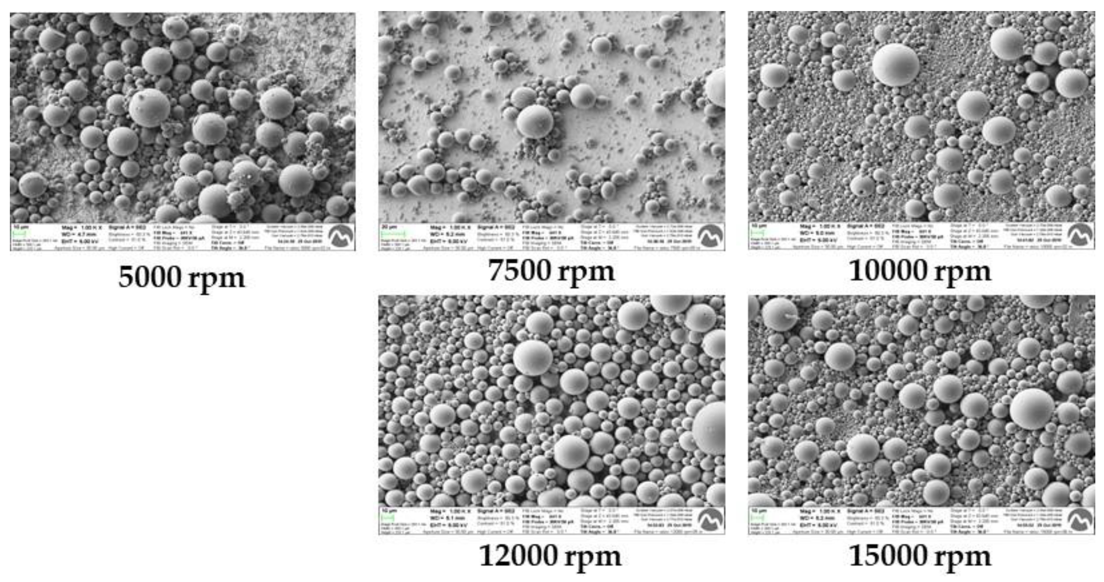
Scanning electron microscopy (SEM) and dynamic scattering light (DSL) techniques were used to obtain qualitative and quantitative data on the morphology and size of the prepared particles. The DSL technique specifically measured the obtained particle sizes at different impeller speeds. The data was then analyzed, plotted, and used to validate the CFD model, as discussed in the following sections. For SEM, a Focus Ion Beam Zeiss Neon 40 instrument (Carl Zeiss, Oberkochen, Germany) was used. For DLS, a NanoBrook 90Plus Zeta Instruments (Brookhaven Instruments, Holtsville NY, USA) was used. Figure 2 shows examples of the SEM images obtained for each tested agitator speed.

2.2. CFD Simulation Strategy

A geometrical model of the experimental setup for the simple emulsion microencapsulation process was constructed using Ansys DesignModeler. The rotor and stator sections of the agitator were modeled as separate volumes connected through a numerical interface, enabling the use of a MRF approach for the rotational frame during the CFD simulation setup.
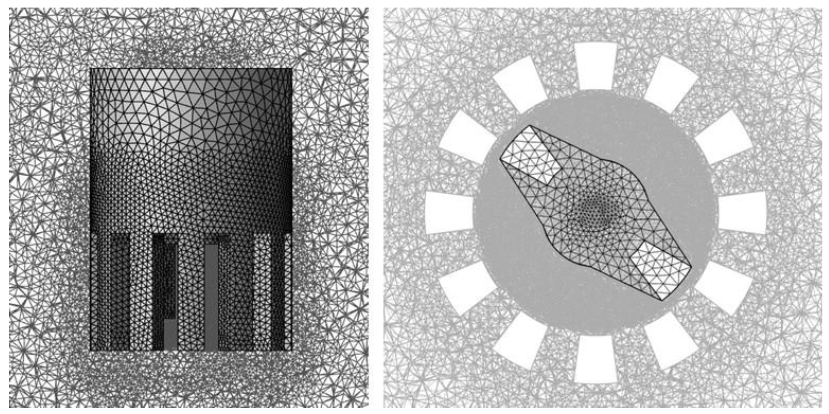
A tetrahedral mesh was generated using Ansys Meshing, with a global average element size of 0.4 mm for the entire domain. To ensure mesh independence, the surface meshes of the agitator rotor and stator walls were successively refined. Steady-state MRF CFD simulations were conducted using water as the operating fluid, with the agitator rotation speed set to 15000 rpm. The rotor blades' torque was recorded for each case and used as the mesh convergence criteria. A local average element size of 0.1 mm was selected for the agitator surface mesh, meeting the mesh independence requirements. The final mesh, shown in Figure 3, consisted of approximately 6400 kEl. Details on the mesh construction process and independency analysis can be found in [47].
Ansys Fluent 2020 R2 [48] was used to generate the CFD model, set up for a turbulent, steady-state flow. A MRF approach was utilized, with rotor blades' rotational speed set between 5,000 and 15,000 rpm to replicate experimental conditions. The model employed a Realizable k-ε model to account for turbulence, and a Eulerian implicit approach was selected for the multiphase modeling. Additionally, a discrete PBM with five particle size bins was implemented, using Luo’s model as the breakage kernel [4] and a turbulence aggregation kernel [48]. Table 2 summarizes the CFD model numerical setup.
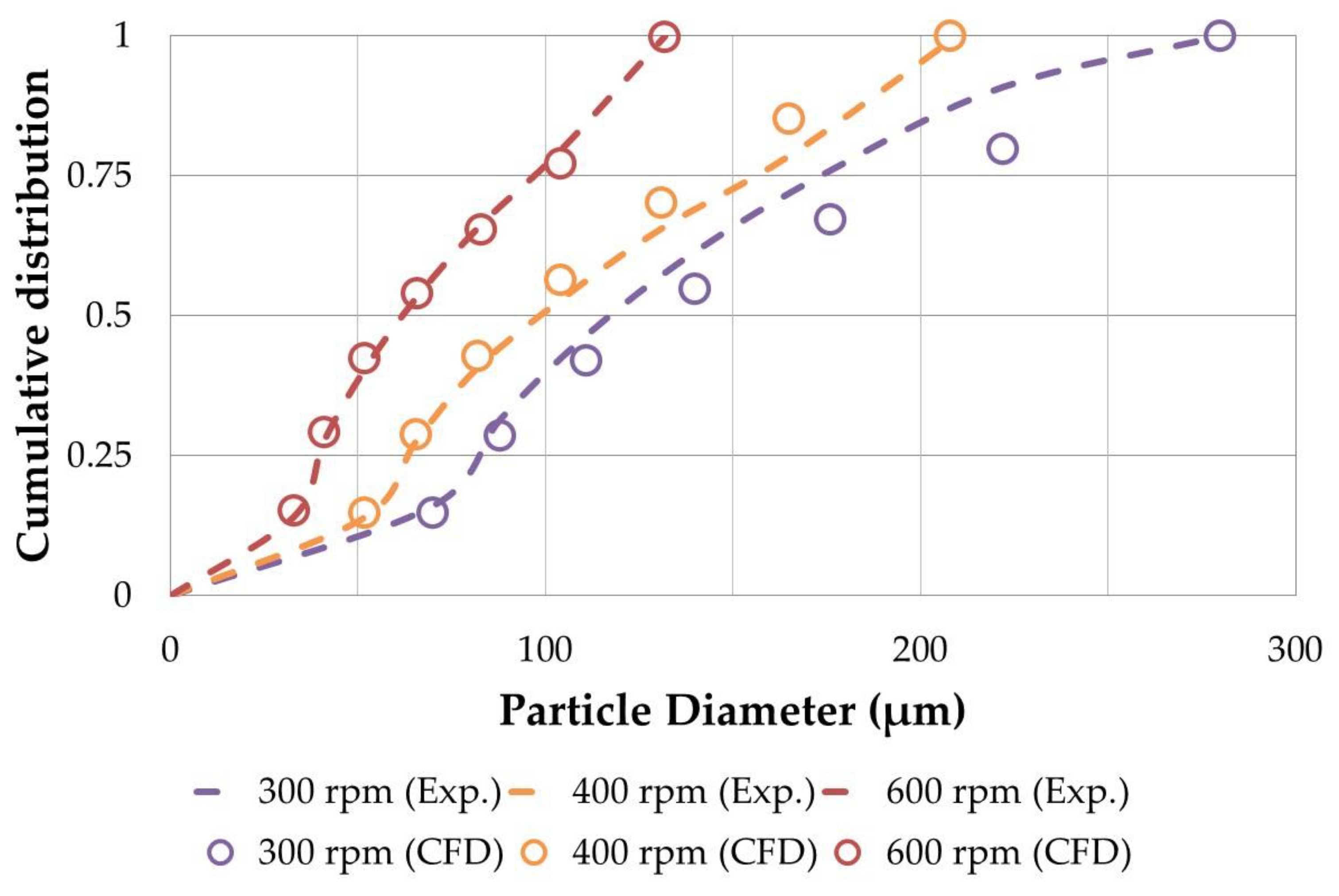
To validate the CFD+PBM simulation strategy, a model was constructed to replicate the study by Roudsari et al. [29], which experimentally and numerically investigated a 15% v/v Conroe oil-water emulsion system at rotational speeds of 300, 400, and 600 rpm. As shown in Figure 4, there is a good agreement between the experimental results reported by Roudsari et al. and the outcomes of the CFD model, demonstrating the model's accuracy in simulating the emulsion system and its reliability for predicting droplet size distributions in emulsification processes.
The emulsion microencapsulation simulations were executed on a workstation equipped with an Intel® Xeon® W-2265 CPU operating at 3.50 GHz. This processor features 12 cores with hyperthreading technology, resulting in a total of 24 logical processors available for parallel computations. The workstation also provides 128 GB of RAM to meet the memory requirements of the simulations. All cases were parallelized across 12 processors, achieving an average wall-clock time of 3.7 seconds per iteration with peak RAM usage reaching approximately 10.5 GB. Local bin fraction and flow velocity monitors were added to check for convergence. Simulations took up to 25000 iterations/26 hours to converge.

3. Results and Discussion

For all studied cases, the numerical results obtained for particle sizes and cumulative size distributions at different agitation speeds were compared against the SEM and DLS results obtained from the single emulsion experiments.

3.1. Experimental Particle Size Distributions

DLS was used to determine the experimental size distribution. For each agitator rotational speed tested, three samples were processed. Table 3 summarizes the obtained average particle sizes for each case.
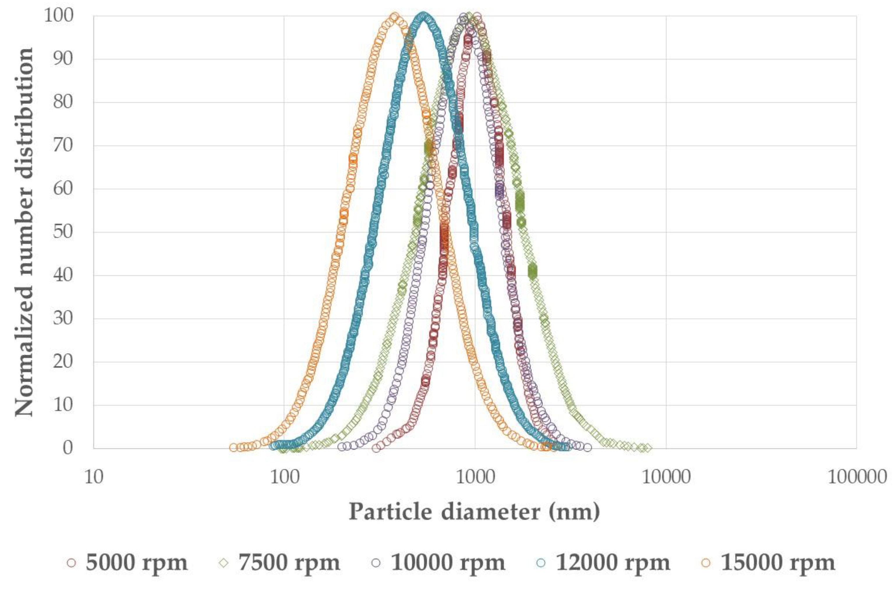
Figure 5 shows an example of the size distributions obtained. The results indicate that for rotational speeds up to 10,000 rpm, the average particle diameter remains around 103 nm. Beyond this speed, the average particle size drops almost by half with a 25% increase in agitation speed. It is known that the emulsification process exhibits two regimes based on droplet and turbulent flow interactions: turbulent inertial and turbulent viscous. In the turbulent inertial regime, drops are larger than the smallest turbulent eddies in the continuous phase, while in the turbulent viscous regime, drops are smaller than these eddies. Lower impeller speeds result in larger droplets due to reduced turbulent energy to break down the dispersed phase, whereas higher speeds produce smaller droplets as greater turbulent kinetic energy allows smaller eddies to fragment the drops [49].

3.2. CFD + PBM Model Performance

Due to the computational expense of solving PBM equations simultaneously with multiphase flow and turbulence equations, only 5 bins were used to compute particle number densities. Although this limitation can introduce discretization errors, literature suggests that 5 bins are sufficient for satisfactory results [27]. To validate the model, simulated droplet size distributions at different impeller speeds were compared to experimental data from DLS analysis.

3.2.1. Particle Number Densities

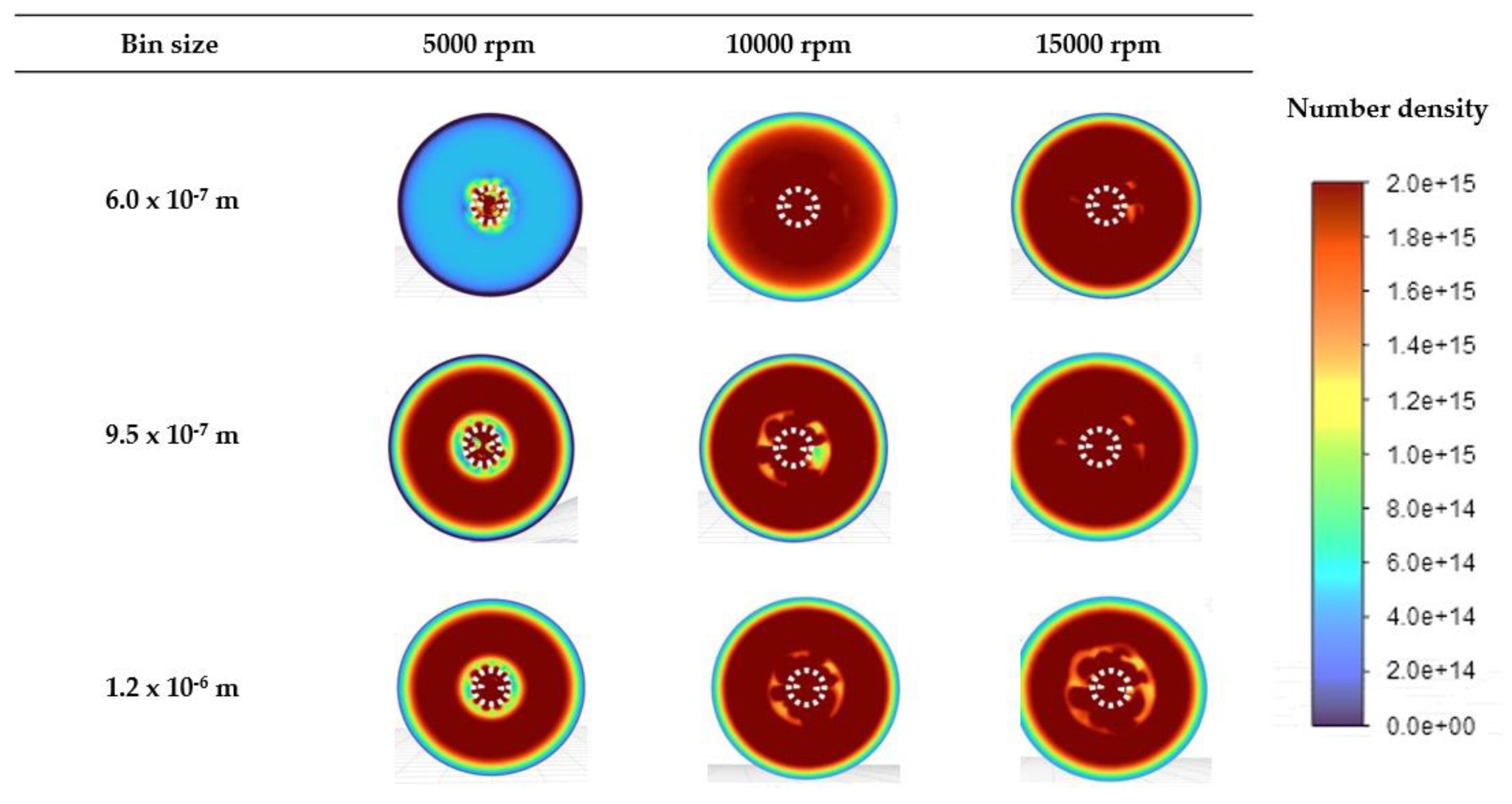
Figure 6 presents the particle number density contours from the CFD simulations for three different particle sizes and agitation speeds in a radial plane intersecting the agitator impeller. The results show higher particle number densities for larger particles at 5000 rpm, and the formation of smaller particles significantly increases with higher agitator rotational speeds. This is consistent with the experimental observations and the DLS data shown in the prior section.
The predicted number density contours for the smallest bin size (6.0 x 10⁻⁶ m) at 10000 rpm and 15000 rpm display similar particle densities across most of the plane, whereas at 5000 rpm, these smaller particles are confined to the high-shear agitator area. This indicates that achieving turbulent viscous regimes throughout the entire flow domain is crucial for preventing the coalescence of small droplets formed near the agitator when they move to regions with lower turbulence. By visually comparing the contours for the smallest bin size, it becomes evident that the mixing system reaches a turbulent inertial regime at an agitation speed of 10000 rpm, ensuring consistent particle size distribution across the domain, thus optimizing the emulsification process.

3.2.2. Particle Size Distribution

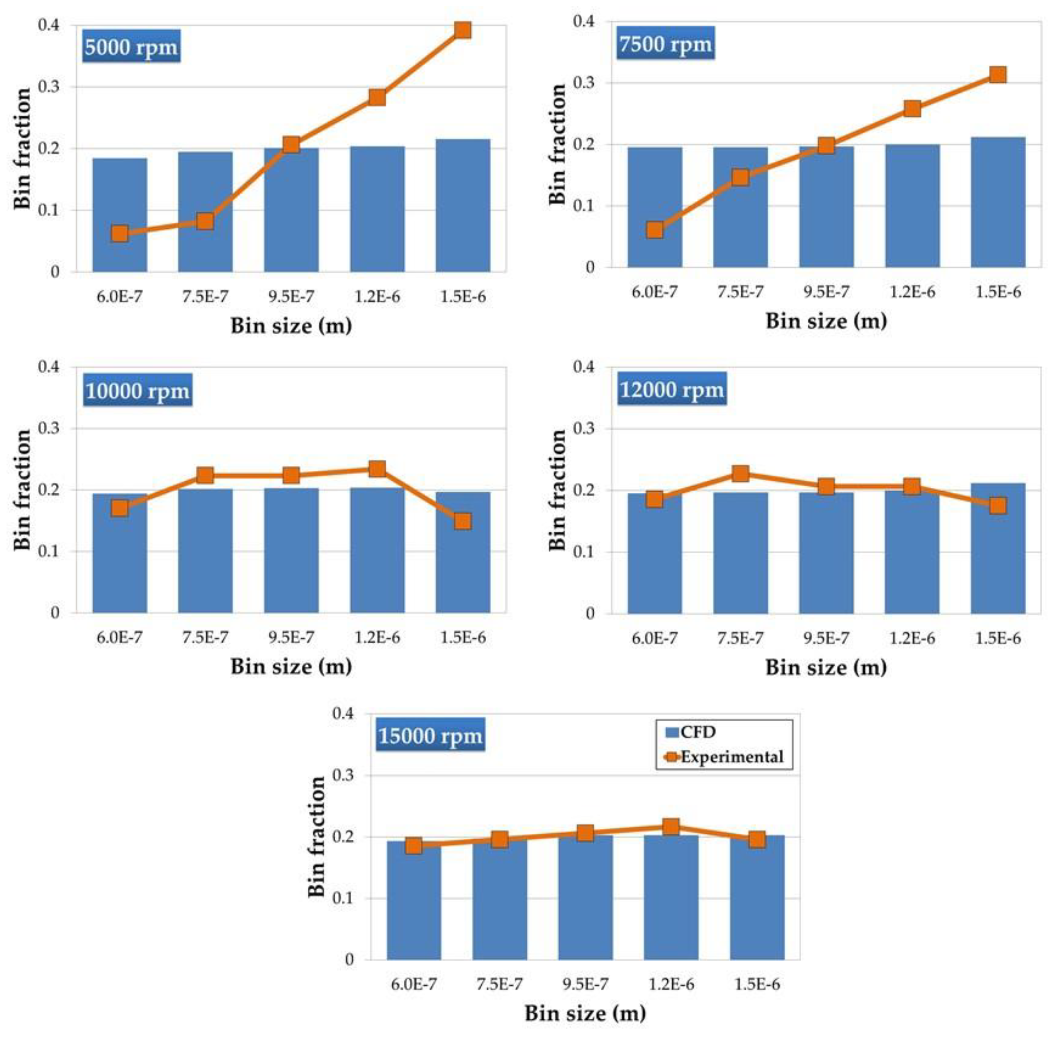
Figure 7 shows the bin fraction for various particle sizes at different rotational speeds, comparing CFD simulations (blue bars) with experimental data (orange lines). At low agitation speeds (5000/7500 rpm), the experimental results show larger fractions for larger particle sizes, indicating that lower agitation speeds favor the formation of larger particles, consistent with a turbulent viscous emulsification regime. For these low-speed cases, The CFD simulations underestimates these larger particles, probably signaling that the turbulence model is overestimating the turbulent kinetic energy (thus obtaining smaller eddies) under those flow conditions.
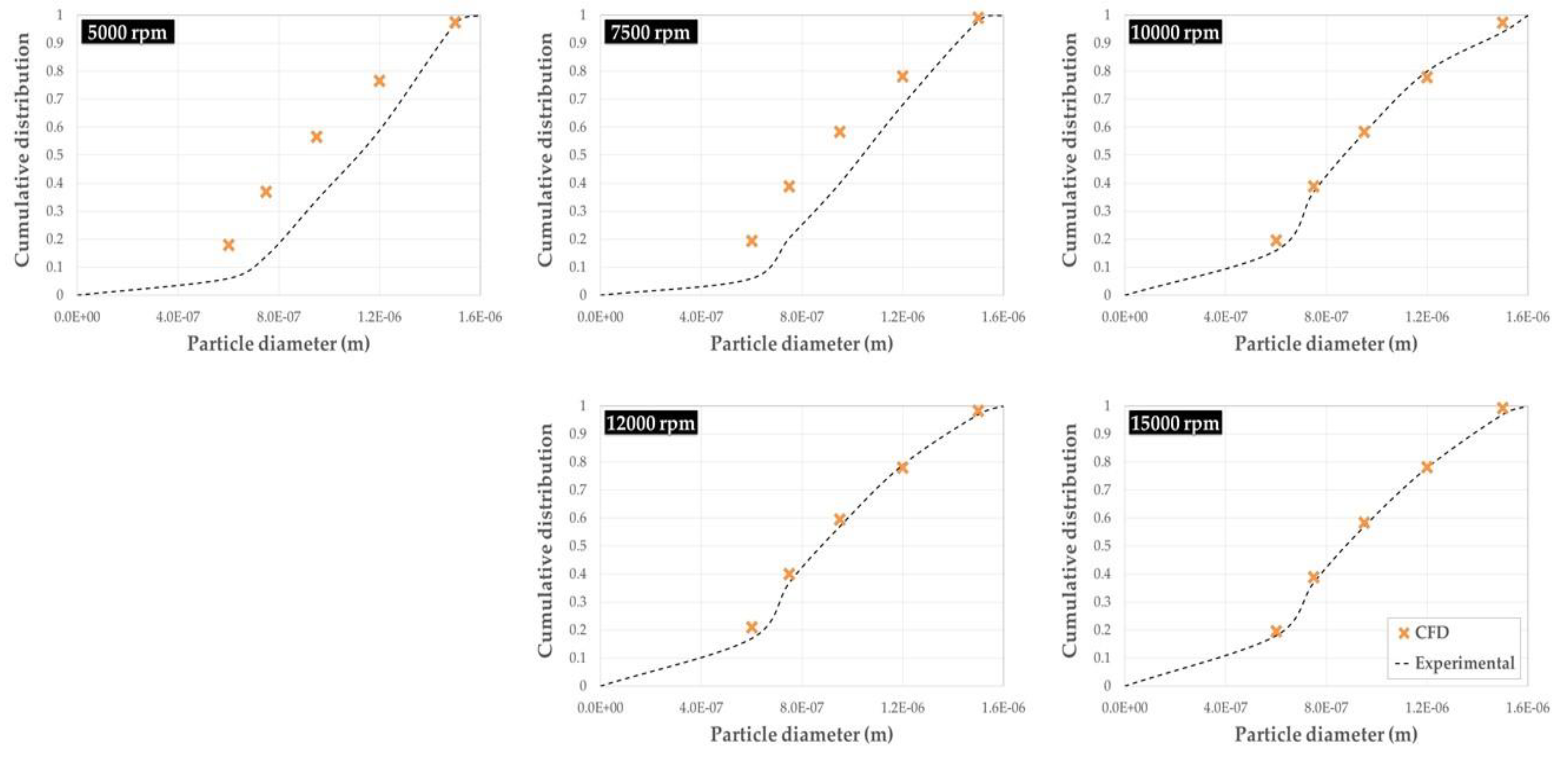
As the rotational speed increases (10000 rpm or above), the experimental and CFD results exhibit a better agreement across all particle sizes, reflecting a transition towards a turbulent inertial regime. However, the simulations tend to slightly underestimate the fraction of the smallest particles. The cumulative distribution of particle diameters for various rotational speeds presented in Figure 8 highlight the aforementioned. The CFD model fails to capture the size distribution trend at lower speeds (5000 rpm and 7500 rpm), likely making it not suitable for turbulent viscous emulsification conditions
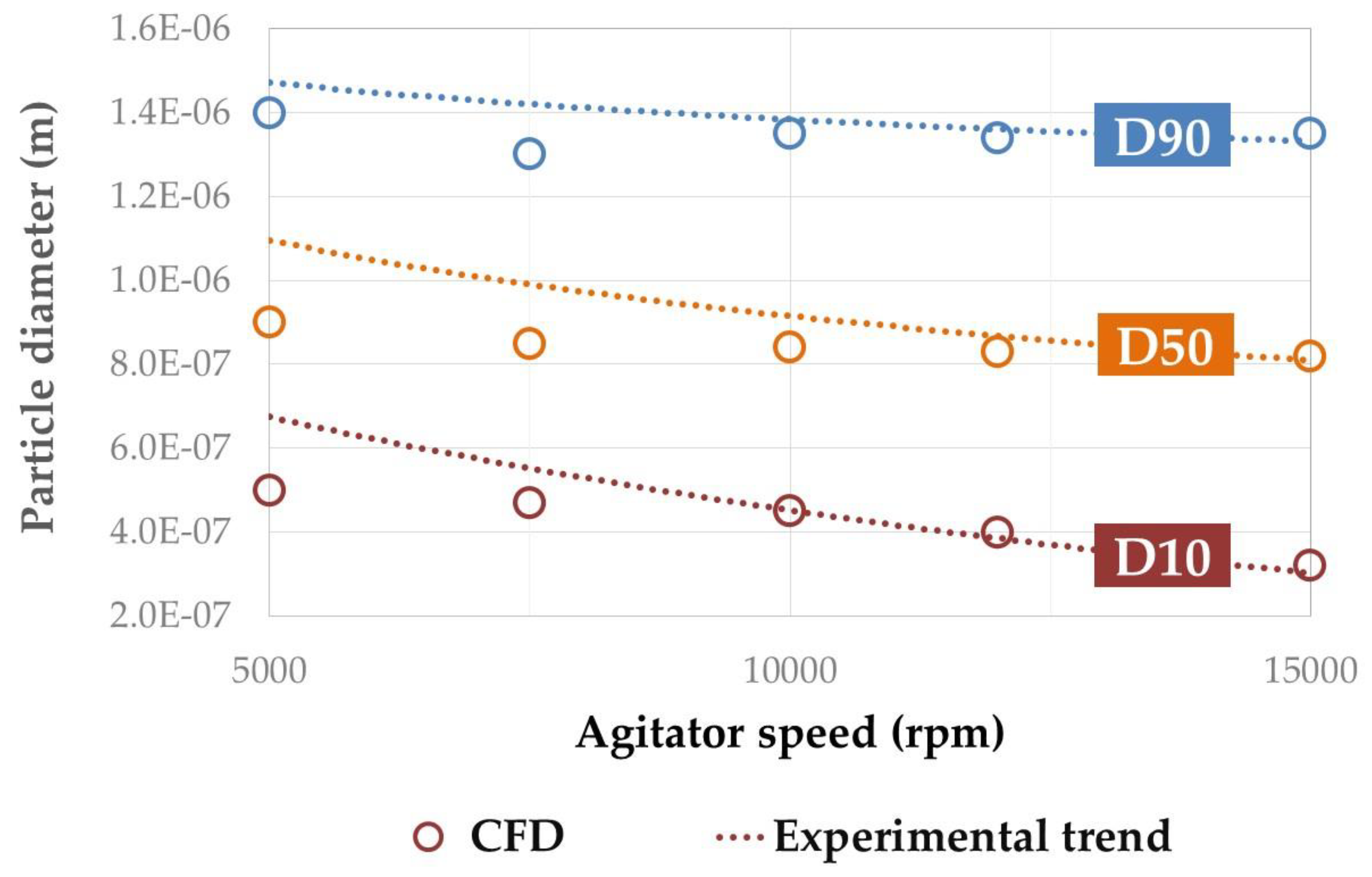
The particle size distribution obtained from simulations was analyzed using D10, D50, and D90 metrics, representing the particle diameters at the 10th, 50th, and 90th percentiles, respectively. Figure 9 illustrates these results, providing a clearer view of the trends observed in the cumulative size distributions shown in Figure 8.
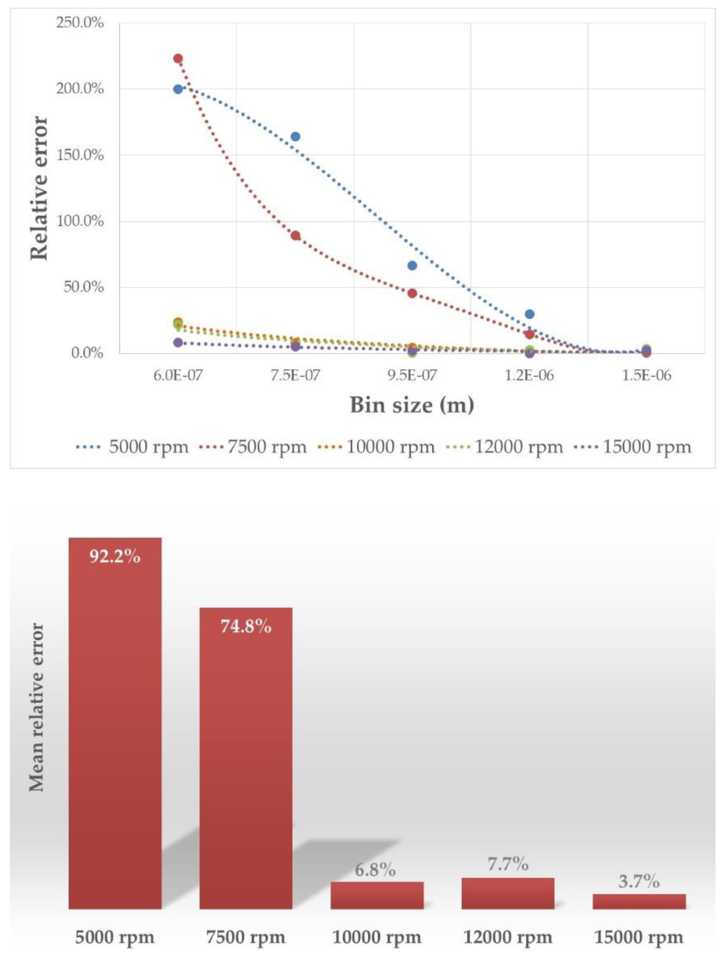
Figure 10 presents the computed relative errors by bin size and agitation speed, revealing higher errors in particle size distribution at lower agitation speeds. It is worth noticing that the largest relative errors occur for smaller particle sizes. Despite minor discrepancies, the CFD simulations closely align with the experimental data at higher agitation speeds (>10000 rpm), validating the simulation strategy's accuracy in predicting particle size distributions under turbulent viscous operational conditions, with acceptable errors below 10%. However, the model fails to accurately capture the flow characteristics at lower agitation speeds (<7500 rpm) within the turbulent inertial regime, resulting in significantly higher mean errors, meaning that the simulation is unable to accurately capture the flow field and dynamics under those operating conditions. This behavior was also observed in the validation case results (Figure 4).
At lower agitation speeds, as the turbulence level decreases, the flow regime may transition to a turbulent viscous regime, where different mechanisms govern droplet breakup and coalescence. The CFD model may struggle to accurately capture these regime-dependent phenomena at lower flow velocities, likely due to the performance of the turbulence model used [50]. As turbulence intensity increases, the influence of interfacial forces, such as surface tension and viscous forces, becomes less significant compared to the turbulent forces acting on the droplets [51], leading to better agreement between experimental and simulation results at higher speeds.
These results highlight the necessity for further research to ensure suitable turbulence model selection for the CFD modeling process. A known issue of the Realizable k-ϵ model is its tendency to overpredict turbulent kinetic energy and underpredict energy dissipation in high mixing flow conditions [52], which may explain its higher inaccuracy at low agitation speeds. Exploring scale-adaptive turbulence models could potentially improve the accuracy of CFD simulations across varying flow regimes. Additionally, investigating alternative turbulence models that can better account for the transition between different flow regimes could enhance the model's predictive capabilities at lower agitation speeds.

4. Conclusions

Computational fluid dynamics (CFD) proves to be a valuable tool for gaining insight into complex processes such as polymer microencapsulation by emulsification. The combination of a population balance model with a Eulerian multiphase framework and a moving reference frame approach is effective in predicting number densities and particle size distributions for such processes.
The model successfully captures the intricate fluid dynamics involved, demonstrating good agreement between experimental and simulation results. Specifically, at higher agitation speeds (>10000 rpm), the CFD model accurately represents the underlying turbulent flow phenomena. The agreement between simulated and experimental data at these speeds indicates that the model effectively captures the turbulent inertial flow conditions, validating its capability to predict droplet behavior and size distribution under high-shear conditions.
However, discrepancies at lower speeds (<7500 rpm) reveal challenges in accurately capturing turbulent viscous regimes. In these low-speed cases, CFD simulations tend to underestimate larger particles, likely due to an overestimation of turbulent kinetic energy, resulting in smaller predicted eddies. This discrepancy at lower impeller speeds underscores the importance of comprehensive experimental validation across a wide range of operating conditions.
While the current CFD model demonstrates overall good predictive accuracy, its performance at lower agitation speeds needs improvement. Future work should focus on extensive experimental validation across a broader range of operating conditions, to better characterize the turbulent viscous and turbulent inertial regimes. This will help identify and address the limitations of the current CFD model, ensuring its reliability and accuracy for different flow conditions. The integration of more advanced turbulence models and improved computational techniques could further refine the predictions and provide deeper insights into the droplet dynamics and particle size distributions in polymer microencapsulation processes.
By addressing the identified discrepancies and enhancing the model's capabilities, CFD can become an even more powerful tool for optimizing and controlling microencapsulation processes, ultimately leading to more efficient and effective industrial applications. The continued development and validation of CFD models will play a crucial role in advancing our understanding of complex fluid dynamics and improving the design and scale-up of polymer microencapsulation processes.

Author Contributions

Conceptualization, A.G. and L.V.; methodology, A.G. and L.V.; validation, M.Q.; formal analysis, M.Q.; investigation, M.Q.; writing—original draft preparation, M.Q.; writing—review and editing, A.G.; supervision, L.V. All authors have read and agreed to the published version of the manuscript.

Funding

This research received no external funding.

Institutional Review Board Statement

Not applicable.

Informed Consent Statement

Not applicable.

Data Availability Statement

Data are available upon reasonable request.

Conflicts of Interest

The authors declare no conflicts of interest.

References

  1. Kolhe, P.; Randhe, G.; Shingote, V.; Thorat, S. A Review: Microencapsulation. International Research Journal of Modernization in Engineering Technology and Science 2024, 06, 149–156. [Google Scholar]
  2. Ibraheem, U.; Rehman, A.; Ahmed, N. Microencapsulation: Methodologies and Applications. Novel Formulations and Future Trends: Recent and Future Trends in Pharmaceutics, Volume 3 2024, 3, 31–60. [Google Scholar] [CrossRef]
  3. Elkalla, E.; Khizar, S.; Tarhini, M.; Lebaz, N.; Zine, N.; Jaffrezic-Renault, N.; Errachid, A.; Elaissari, A. Core-Shell Micro/Nanocapsules: From Encapsulation to Applications. J Microencapsul 2023, 40, 125–156. [Google Scholar] [CrossRef] [PubMed]
  4. Luo, H.; Svendsen, H.F. Theoretical Model for Drop and Bubble Breakup in Turbulent Dispersions. AIChE Journal 1996, 42, 1225–1233. [Google Scholar] [CrossRef]
  5. Thakur, N.; Murthy, H. Simulation Study of Droplet Formation in Inkjet Printing Using ANSYS FLUENT. J Phys Conf Ser 2022, 2161, 012026. [Google Scholar] [CrossRef]
  6. Niamah, A.K.; Gddoa Al-Sahlany, S.T.; Ibrahim, S.A.; Verma, D.K.; Thakur, M.; Singh, S.; Patel, A.R.; Aguilar, C.N.; Utama, G.L. Electro-Hydrodynamic Processing for Encapsulation of Probiotics: A Review on Recent Trends, Technological Development, Challenges and Future Prospect. Food Biosci 2021, 44, 101458. [Google Scholar] [CrossRef]
  7. Alotaibi, H.; Abeykoon, C.; Soutis, C.; Jabbari, M. A Numerical Thermo-Chemo-Flow Analysis of Thermoset Resin Impregnation in LCM Processes. Polymers (Basel) 2023, 15, 1572. [Google Scholar] [CrossRef] [PubMed]
  8. Yuile, A.; Schulz, A.; Wiss, E.; Müller, J.; Wiese, S. The Simulated Effect of Adding Solder Layers on Reactive Multilayer Films Used for Joining Processes. Applied Sciences 2022, 12, 2397. [Google Scholar] [CrossRef]
  9. Ma, G. Microencapsulation of Protein Drugs for Drug Delivery: Strategy, Preparation, and Applications. Journal of Controlled Release 2014, 193, 324–340. [Google Scholar] [CrossRef] [PubMed]
  10. Khandbahale, S. V. Microencapsulation-A Novel Approach in Drug Delivery: A Review. Asian Journal of Research in Pharmaceutical Science 2020, 10, 39. [Google Scholar] [CrossRef]
  11. Zhu, J.; He, J.; Zhou, J.; Yang, Z.; Li, X.; Li, Y.; You, Z. Recent Progress in Microencapsulation Technology and Its Applications in Petroleum Industry. J Mol Liq 2024, 407, 125162. [Google Scholar] [CrossRef]
  12. Desai, K.G.H.; Jin Park, H. Recent Developments in Microencapsulation of Food Ingredients. Drying Technology 2005, 23, 1361–1394. [Google Scholar] [CrossRef]
  13. Calderón-Oliver, M.; Ponce-Alquicira, E. The Role of Microencapsulation in Food Application. Molecules 2022, 27, 1499. [Google Scholar] [CrossRef] [PubMed]
  14. Carvalho, I.T.; Estevinho, B.N.; Santos, L. Application of Microencapsulated Essential Oils in Cosmetic and Personal Healthcare Products – a Review. Int J Cosmet Sci 2016, 38, 109–119. [Google Scholar] [CrossRef] [PubMed]
  15. Martins, I.M.; Barreiro, M.F.; Coelho, M.; Rodrigues, A.E. Microencapsulation of Essential Oils with Biodegradable Polymeric Carriers for Cosmetic Applications. Chemical Engineering Journal 2014, 245, 191–200. [Google Scholar] [CrossRef]
  16. Randolph, A.D.; Larson, M.A. Theory of Particulate Processes; Elsevier, 1971; ISBN 9780125796507.
  17. Hounslow, M.J.; Ryall, R.L.; Marshall, V.R. A Discretized Population Balance for Nucleation, Growth, and Aggregation. AIChE Journal 1988, 34, 1821–1832. [Google Scholar] [CrossRef]
  18. Heath, A.R.; Koh, P.T.L. Combined Population Balance and CFD Modeling of Particle and Aggregation by Polymeric Flocculant. In Proceedings of the Third International Conference on CFD in the Minerals and Porcess Industries; Melbourne, Australia; 2003; pp. 339–344. [Google Scholar]
  19. Agterof, W.G.M.; Vaessen, G.E.J.; Haagh, G.A.A.V.; Klahn, J.K.; Janssen, J.J.M. Prediction of Emulsion Particle Sizes Using a Computational Fluid Dynamics Approach. Colloids Surf B Biointerfaces 2003, 31, 141–148. [Google Scholar] [CrossRef]
  20. Kerdouss, F.; Bannari, A.; Proulx, P.; Bannari, R.; Skrga, M.; Labrecque, Y. Two-Phase Mass Transfer Coefficient Prediction in Stirred Vessel with a CFD Model. Comput Chem Eng 2008, 32, 1943–1955. [Google Scholar] [CrossRef]
  21. Bayraktar, E.; Mierka, O.; Platte, F.; Kuzmin, D.; Turek, S. Numerical Aspects and Implementation of Population Balance Equations Coupled with Turbulent Fluid Dynamics. Comput Chem Eng 2011, 35, 2204–2217. [Google Scholar] [CrossRef]
  22. Lehr, F.; Millies, M.; Mewes, D. Bubble-Size Distributions and Flow Fields in Bubble Columns. AIChE Journal 2002, 48, 2426–2443. [Google Scholar] [CrossRef]
  23. Schütz, S.; Gorbach, G.; Piesche, M. Modeling Fluid Behavior and Droplet Interactions during Liquid–Liquid Separation in Hydrocyclones. Chem Eng Sci 2009, 64, 3935–3952. [Google Scholar] [CrossRef]
  24. Silva, L.F.L.R.; Lage, P.L.C. Development and Implementation of a Polydispersed Multiphase Flow Model in OpenFOAM. Comput Chem Eng 2011, 35, 2653–2666. [Google Scholar] [CrossRef]
  25. Silva, L.F.L.R.; Damian, R.B.; Lage, P.L.C. Implementation and Analysis of Numerical Solution of the Population Balance Equation in CFD Packages. Comput Chem Eng 2008, 32, 2933–2945. [Google Scholar] [CrossRef]
  26. Silva, L.F.L.R.; Rodrigues, R.C.; Mitre, J.F.; Lage, P.L.C. Comparison of the Accuracy and Performance of Quadrature-Based Methods for Population Balance Problems with Simultaneous Breakage and Aggregation. Comput Chem Eng 2010, 34, 286–297. [Google Scholar] [CrossRef]
  27. Vladisavljević, G.T.; Kobayashi, I.; Nakajima, M. Effect of Dispersed Phase Viscosity on Maximum Droplet Generation Frequency in Microchannel Emulsification Using Asymmetric Straight-through Channels. Microfluid Nanofluidics 2011, 10, 1199–1209. [Google Scholar] [CrossRef]
  28. Liao, Y.; Lucas, D. A Literature Review of Theoretical Models for Drop and Bubble Breakup in Turbulent Dispersions. Chem Eng Sci 2009, 64, 3389–3406. [Google Scholar] [CrossRef]
  29. Hinze, J.O. Fundamentals of the Hydrodynamic Mechanism of Splitting in Dispersion Processes. AIChE Journal 1955, 1, 289–295. [Google Scholar] [CrossRef]
  30. Lebaz, N.; Azizi, F.; Sheibat-Othman, N. Modeling Droplet Breakage in Continuous Emulsification Using Static Mixers in the Framework of the Entire Spectrum of Turbulent Energy. Ind Eng Chem Res 2022, 61, 541–553. [Google Scholar] [CrossRef]
  31. Andersson, R.; Andersson, B. Modeling the Breakup of Fluid Particles in Turbulent Flows. AIChE Journal 2006, 52, 2031–2038. [Google Scholar] [CrossRef]
  32. Rommel, W.; Meon, W.; Blass, E. Hydrodynamic Modeling of Droplet Coalescence at Liquid-Liquid Interfaces. Sep Sci Technol 1992, 27, 129–159. [Google Scholar] [CrossRef]
  33. Frising, T.; Noïk, C.; Dalmazzone, C. The Liquid/Liquid Sedimentation Process: From Droplet Coalescence to Technologically Enhanced Water/Oil Emulsion Gravity Separators: A Review. J Dispers Sci Technol 2006, 27, 1035–1057. [Google Scholar] [CrossRef]
  34. Kamp, J.; Villwock, J.; Kraume, M. Drop Coalescence in Technical Liquid/Liquid Applications: A Review on Experimental Techniques and Modeling Approaches. Reviews in Chemical Engineering 2017, 33, 1–47. [Google Scholar] [CrossRef]
  35. Liao, Y.; Lucas, D. A Literature Review on Mechanisms and Models for the Coalescence Process of Fluid Particles. Chem Eng Sci 2010, 65, 2851–2864. [Google Scholar] [CrossRef]
  36. Fathi Roudsari, S.; Turcotte, G.; Dhib, R.; Ein-Mozaffari, F. CFD Modeling of the Mixing of Water in Oil Emulsions. Comput Chem Eng 2012, 45, 124–136. [Google Scholar] [CrossRef]
  37. Fathi Roudsari, S.; Ein-Mozaffari, F.; Dhib, R. Use of CFD in Modeling MMA Solution Polymerization in a CSTR. Chemical Engineering Journal 2013, 219, 429–442. [Google Scholar] [CrossRef]
  38. Roudsari, S.F. Experimental and CFD Investigation of the Mixing of MMA Emulsion Polymerization in a Stirred Tank Reactor. Ph.D. Thesis, Toronto Metropolitan University, 2015.
  39. Patil, A. V.; Johansen, S.T. Computaional and Experimental Study of Oil-Water Emulsion Flow and Stability in Stirred Tanks. In Proceedings of the The 11th International Conference on CFD in the Minerals and Process Industries; Solnordal, C.B., Liovic, P., Delaney, G.W., Cummins, S.J., Schwarz, M.P., Witt, P.J., Eds.; Melbourne, Australia, 2015; pp. 1–7.
  40. Zhang, J.; Xu, S.; Li, W. High Shear Mixers: A Review of Typical Applications and Studies on Power Draw, Flow Pattern, Energy Dissipation and Transfer Properties. Chemical Engineering and Processing: Process Intensification 2012, 57–58, 25–41. [Google Scholar] [CrossRef]
  41. Cardoso, F.A.R.; Rezende, R.V.P.; Almeida, R.A.; Mezzomo, N.; Ferreira, S.R.S.; Meier, H.F.; Cardozo-Filho, L. CFD-Based Modeling of Precipitation by Supercritical Anti-Solvent Process of Microparticles from Grape Pomace Extract with Population Balance Approach. J Supercrit Fluids 2018, 133, 519–527. [Google Scholar] [CrossRef]
  42. Cheng, J.C.; Fox, R.O. Kinetic Modeling of Nanoprecipitation Using CFD Coupled with a Population Balance. Ind Eng Chem Res 2010, 49, 10651–10662. [Google Scholar] [CrossRef]
  43. Lavino, A.D.; Ferrari, M.; Barresi, A.A.; Marchisio, D. Effect of Different Good Solvents in Flash Nano-Precipitation via Multi-Scale Population Balance Modeling-CFD Coupling Approach. Chem Eng Sci 2021, 245, 116833. [Google Scholar] [CrossRef]
  44. Gobert, S.R.L.; Kuhn, S.; Teixeira, R.F.A.; Braeken, L.; Thomassen, L.C.J. Scale-up of Continuous Microcapsule Production. Chemical Engineering and Processing - Process Intensification 2020, 153, 107989. [Google Scholar] [CrossRef]
  45. IKA-Werke GmbH % Co S 18N-19G Dispersing Tool Available online:. Available online: https://www.ika.com/en/Products-LabEq/Dispersers-pg177/S-18-N-19-G-Dispersing-tool-L004640/ (accessed on 18 July 2024).
  46. Telstar LyoQuest Basic Research Freeze Dryer Available online:. Available online: https://www.telstar.com/en/laboratory-equipment/laboratory-freeze-dryers/basic-research-benchtop-freeze-dryer/ (accessed on 18 July 2024).
  47. Parra Mondejar, A. Simulació Fluidodinàmica (CFD) de Formació de Nanoparticules a Escala Industrial. B.Sc. Thesis, Universitat Politècnica de Catalunya, 2016.
  48. Ansys Inc. Ansys Fluent 2020.
  49. Vankova, N.; Tcholakova, S.; Denkov, N.D.; Ivanov, I.B.; Vulchev, V.D.; Danner, T. Emulsification in Turbulent Flow: 1. Mean and Maximum Drop Diameters in Inertial and Viscous Regimes. J Colloid Interface Sci 2007, 312, 363–380. [Google Scholar] [CrossRef] [PubMed]
  50. Sajjadi, S. Nanoemulsion Formation by Phase Inversion Emulsification: On the Nature of Inversion. Langmuir 2006, 22, 5597–5603. [Google Scholar] [CrossRef] [PubMed]
  51. Boxall, J.A.; Koh, C.A.; Sloan, E.D.; Sum, A.K.; Wu, D.T. Measurement and Calibration of Droplet Size Distributions in Water-in-Oil Emulsions by Particle Video Microscope and a Focused Beam Reflectance Method. Ind Eng Chem Res 2010, 49, 1412–1418. [Google Scholar] [CrossRef]
  52. Guardo, A.; Coussirat, M.; Larrayoz, M.A.; Recasens, F.; Egusquiza, E. Influence of the Turbulence Model in CFD Modeling of Wall-to-Fluid Heat Transfer in Packed Beds. Chem Eng Sci 2005, 60, 1733–1742. [Google Scholar] [CrossRef]
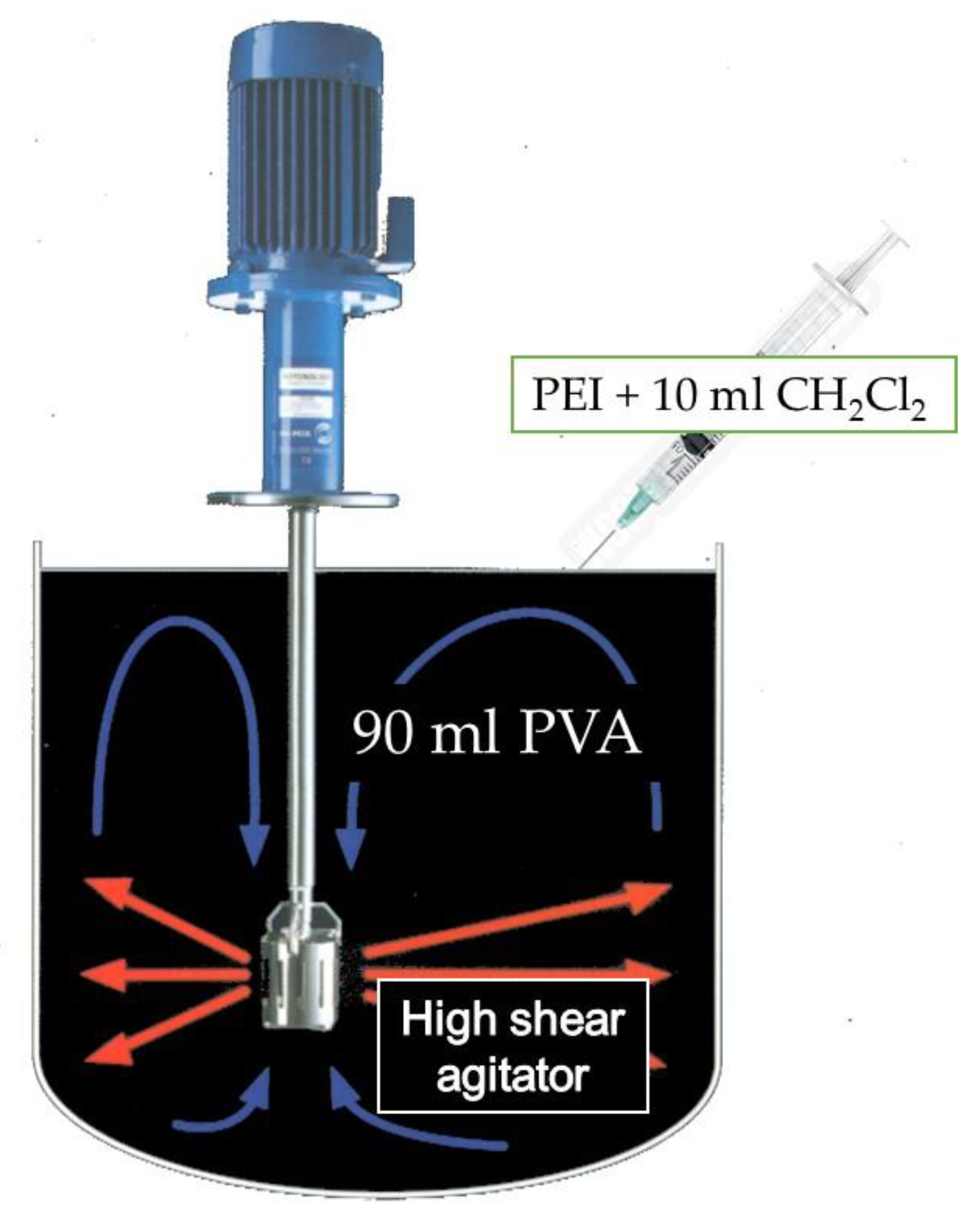
Figure 1. Schematic diagram of the experimental setup.
Preprints 114587 g001
Figure 2. Example of SEM images obtained for the experiments.
Preprints 114587 g002
Figure 3. Details of the computational mesh generated.
Preprints 114587 g003
Figure 4. CFD+PBM strategy validation against experimental results by Roudsari et al. [36.]
Preprints 114587 g004
Figure 5. Particle size distributions obtained for different agitator rotation speeds.
Preprints 114587 g005
Figure 6. Bin number density contours obtained for different agitator rotation speeds.
Preprints 114587 g006
Figure 7. CFD vs. Experimental bin fractions.
Preprints 114587 g007
Figure 8. Cumulative size distributions.
Preprints 114587 g008
Figure 9. Particle diameters at the 10th, 50th and 90th percentile.
Preprints 114587 g009
Figure 10. Computed relative errors.
Preprints 114587 g010
Table 1. Physical properties at 20 ºC and 1 atm.
Material Density (kg/m3) Viscosity (Pa·s)
PEI 1332.7 3.21 x 10⁻¹
PVA 998.00 1.02 x10⁻³
Table 2. CFD model numerical setup.
Parameter Value
Solver Pressure based, double precision
Viscous model Realizable   k ϵ
Multiphase model Eulerian implicit
Population balance model Discrete
Pressure-velocity coupling algorithm SIMPLE
Discretization methods
     Pressure Standard
     Momentum; Turbulence; Phases First order upwind
Under-relaxation factors
     Pressure 0.3
     Momentum; PEI bins 0.5
     Turbulence kinetic energy 0.8
     Turbulence dissipation rate 0.7
Residuals convergence criteria < 0.001
Table 3. Average particle sizes obtained (in nm).
5000 rpm 7500 rpm 10000 rpm 12500 rpm 15000 rpm
Particle diameter 990.7 972.0 944.0 552.5 455.0
Standard deviation 68.13 76.21 126.4 81.72 129.9
Disclaimer/Publisher’s Note: The statements, opinions and data contained in all publications are solely those of the individual author(s) and contributor(s) and not of MDPI and/or the editor(s). MDPI and/or the editor(s) disclaim responsibility for any injury to people or property resulting from any ideas, methods, instructions or products referred to in the content.
Copyright: This open access article is published under a Creative Commons CC BY 4.0 license, which permit the free download, distribution, and reuse, provided that the author and preprint are cited in any reuse.
Prerpints.org logo

Preprints.org is a free preprint server supported by MDPI in Basel, Switzerland.

Subscribe

© 2024 MDPI (Basel, Switzerland) unless otherwise stated