1. Introduction
The need for energy savings and environmental preservation has led to the development of high-strength steels. Structural steels with high yield point are known as high-strength steels (HSS), and when the yield point of steels is above 700 MPa they are called ultra-high strength steels (UHSS) [1]. Both HSS and UHSS have various practical uses, ranging from construction to automotive and spacecraft production. In the modern world, HSS and UHSS play a key role in global warming, as these steels offer high strength combined with reduced vehicle weight and different structures, thus lowering harmful emissions. For instance, lighter trucks made of high-strength steel can carry more goods while emitting the same amount of CO₂ per kilometre [2]. As HSS and UHSS offer the same or increased strength at reduced weight compared to conventional steels, their use allows for more energy-efficient and cost-efficient designs for vehicles, wind turbines, transformers, motors, and other types of construction. This leads to a reduction in energy consumption throughout the lifespan of equipment and construction. Therefore, HSS and UHSS not only enhance structural performance, but also do support environmental preservation by reducing emissions and promoting sustainable practices.
High strength steels obtain their mechanical properties after careful steel composition design and heat treatment or thermo-mechanical treatment. An example of heat-treated ultra-high strength steel is S960QL. S960QL has a high yield strength (up to 960 MPa depending on the thickness) due to the combination of the proper choice of alloying elements and heat treatment – quenching and tempering. S700MC is another example of ultra-high strength steel. The high yield strength of S700MC (700 MPa) is achieved by combination of microalloying and thermo-mechanical treatment, i.e. rolling at elevated temperatures and next accelerated cooling.
Both grades possess good weldability; therefore, S960QL and S700MC weldments are widely used in different welded structures. Numerous studies have been conducted on the structure and mechanical properties of S960QL and S700MC weldments [
3,
4,
5,
6,
7,
8,
9,
10,
11,
12,
13,
14,
15]. Unfortunately, information on the corrosion behaviour of weldments of both steels is hard to find in the specialized literature. It is well known that different zones in the weldments and base metal demonstrate different corrosion rates, and this leads to the formation of corrosion galvanic elements. Nevertheless, a more detailed exploration work on the corrosion behaviour of weldments is needed to assess the lifespan of welded structures and the most probable spot for corrosion to occur to prevent loss of mechanical stability and structural integrity.
The present paper focuses on the determination of corrosion rates of weld metal (fusion zone) of weldments of S960QL and S700MC in the most abundant electrolyte on our planet, i.e. sodium chloride water solution, using accelerated electrochemical testing. As in various applications the use of a standardized weld gap is not suitable, the tested here weldments were made with different welding gaps and the influence of welding gap on corrosion of weld metal was experimentally found.
2. Materials and Methods
The tested specimens were weldments of S960QL and S700MC. The detailed welding procedures are described in [16] and [17]. Both steels were manufactured by Voestalpine Stahl GmbH, Austria. S960QL was as plate with a thickness of 6 mm, and S700MC – hot-rolled sheets with a thickness of 8 mm. The chemical compositions of steels, according to the manufacturer, is given in
Table 1.
The welded parts had dimensions of 500x150x6 mm for S960QL and 500х150х8 mm for S700MC (length, width, thickness), following ISO 15614-1:2017. As welding method submerged arc welding was used, with direct current and reverse polarity DC (+). Four different welding gaps of 0 mm, 4 mm, 6 mm and 8 mm were used as described in [16] and [17]. Except for the welding gap root, which had to be investigated for its impact on the weldments, the joint preparation followed ISO 9692-2:2001. Without a root face, a mechanical bevel was performed at an angle of 30° (for a total of 60°). As a filler material a wire of AWS ER120S-G for S960QL was used, and for S700MC - a wire of AWS ER 100S-G. In both cases the diameter of the filler material was 1.2 mm, and the flux was S A AB 1 56 AC H5 (ISO 14174:2019). The chemical composition of filler materials is shown in
Table 2, and the welding parameters - in
Table 3.
Test specimens of the weldments were cut off after welding to examine the macrostructure and microstructure, and to perform corrosion tests. Macrostructure was examined in two directions – parallel to the welding direction and normal to welding direction. Prior etching for macrostructural analysis, the specimens were wet ground with 240, 320, 400, 500, 600, 800 and 1000 SiC grit. For macrostructure evaluation a saturated FeCl3 water solution was used at room temperature for 15 s. Metallographic examination was done on microsections normal to the welding direction after wet grinding and mechanical polishing with Al2O3 0.5 µm and final polishing – with Al2O3 0.03 µm. A 3% HNO4 alcohol solution was used for etching microsections for 5 s. An optical microscope equipped with a digital camera was used to observe the microstructure and to take microphotographs of it. In the Results section, only a few representative microphotographs are given.
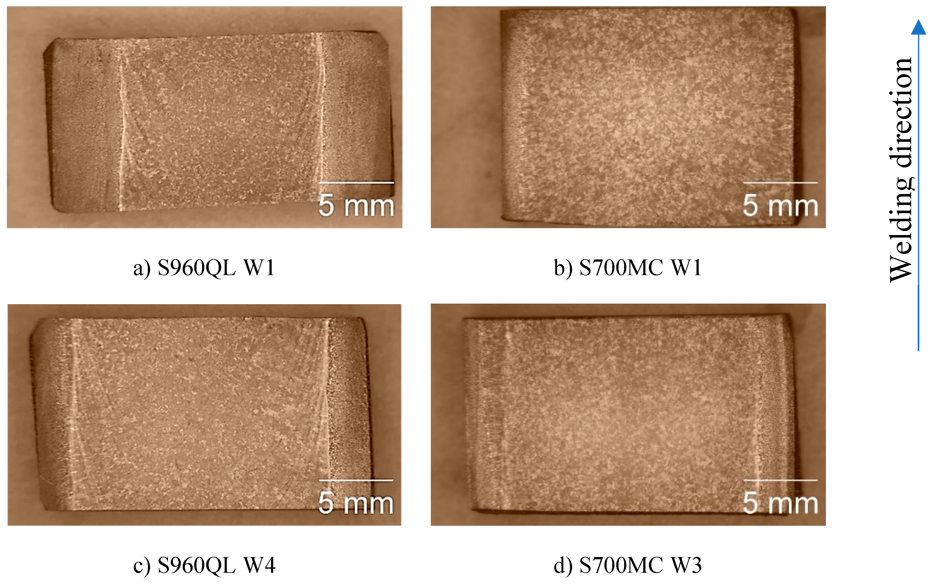
Corrosion rate was evaluated using accelerated electrochemical testing. Electrochemical tests were carried out on the weld metal surface, parallel to the welding direction, as shown in
Figure 1. The tested surfaces were ground and polished as for metallographic examination and cleaned with acetone. As an aggressive environment a neutral 3.5% NaCl water solution was chosen as this is the average sodium chloride concentration in the world ocean [18]. Prior electrochemical test, every specimen was allowed to stabilize in the electrolyte for 50 min. At the end of this stabilization period the steady state potential E
ss was measured against a saturated calomel electrode SCE. The potential of SCE at the test room temperature was +245 mV against standard hydrogen electrode SHE, and all presented here values of potentials are calculated according to this against SHE. Following was linear polarization using a standard three-electrode cell with the tested sample as a working electrode, SCE as a reference electrode and a Pt-counter electrode. The potential was controlled using a Radelkis OH 105 potentiostat equipped with a National Instruments USB-6008 controller connected to a computer. The area of the tested surfaces was 0.5 cm
2, and the rate of potential increase was 1 mV/s, starting from -650 mV up to -250 mV. eL-ChemViewer software [19] was used for Tafel analysis for corrosion current density i
corr and corrosion potential E
corr determination. Using the obtained i
corr values, corrosion penetration rate CR was calculated as described in [20].
3. Results
The present work aims to characterize the weld metal. To evaluate the corrosion behaviour of the weld metal, first macrostructural analysis of the weld metal of weldments was performed.
Figure 1 represents the macrostructure of the surfaces of some of the tested weldments. The weld metal (WM) on longitudinal section of both steels looks similar except for the visible isotherms on S960QL weld metal – curved lines, showing how the pool moved during welding. Near WM boundaries curved dendrites are observed for both steels’ weldments and approaching the centre line of the weldments the shape of WM changes to equiaxed one.
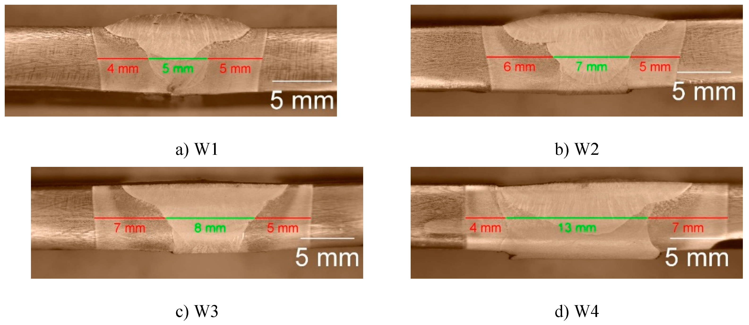
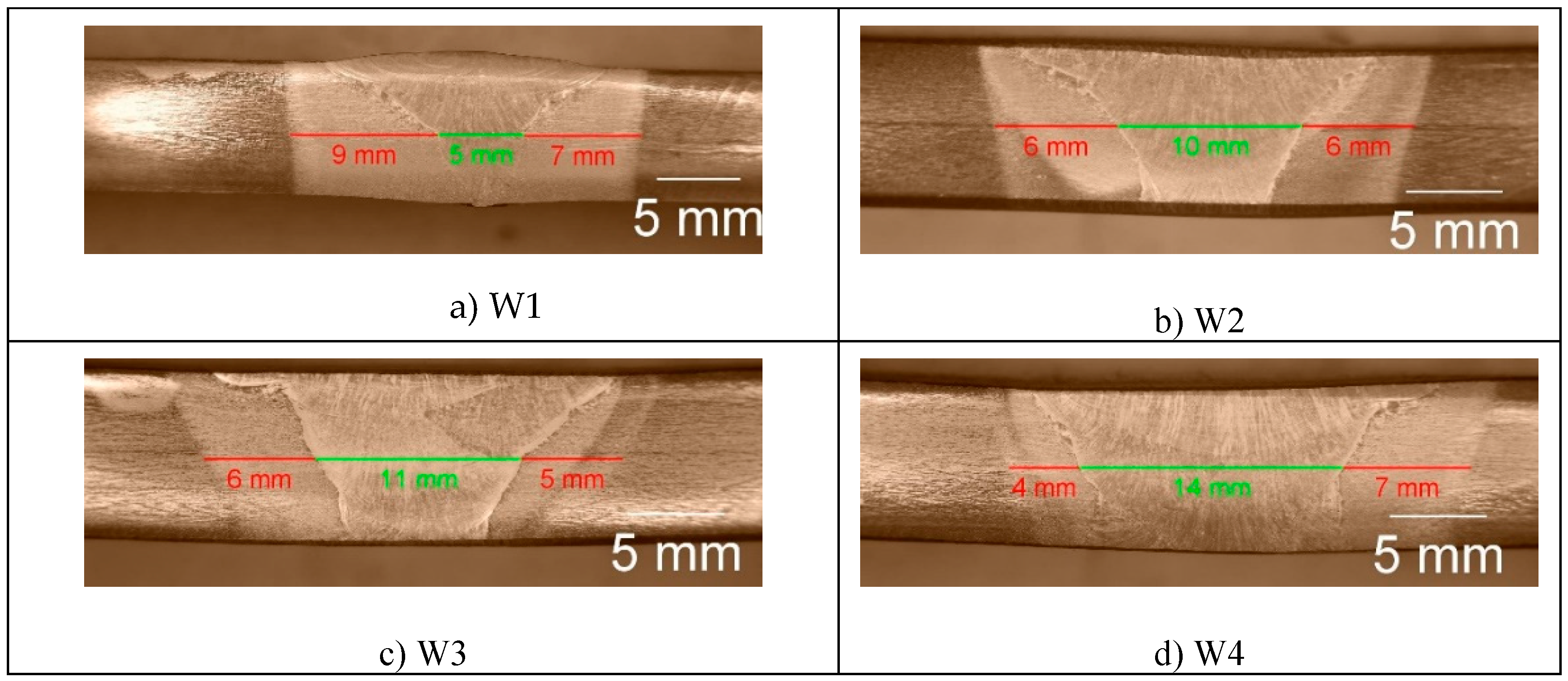
To find faults and depth of fusion, cross sections of the samples of both steels, shown in
Figure 2 and
Figure 3, were observed.
For all welding modes faults are not observed but the weldments show full penetration. With the increase in the weld gap dimension the width of the sum of the different welding zones increases too, expectedly. It is interesting to note that the coarse-grained heat affected zone on weldments of S700MC is narrower than the observed one on weldments of S960QL. The weld metal of all weldments demonstrates a typical dendritic (cast) structure with grains elongated towards the weld root near the weld centre line and toward heat affected zone near the ends of the WM. Increasing the distance between the welded parts leads to an increase in the weld’s asymmetry. Detailed description of the macrostructure of the studied here weldments is given in [17] and [
16].
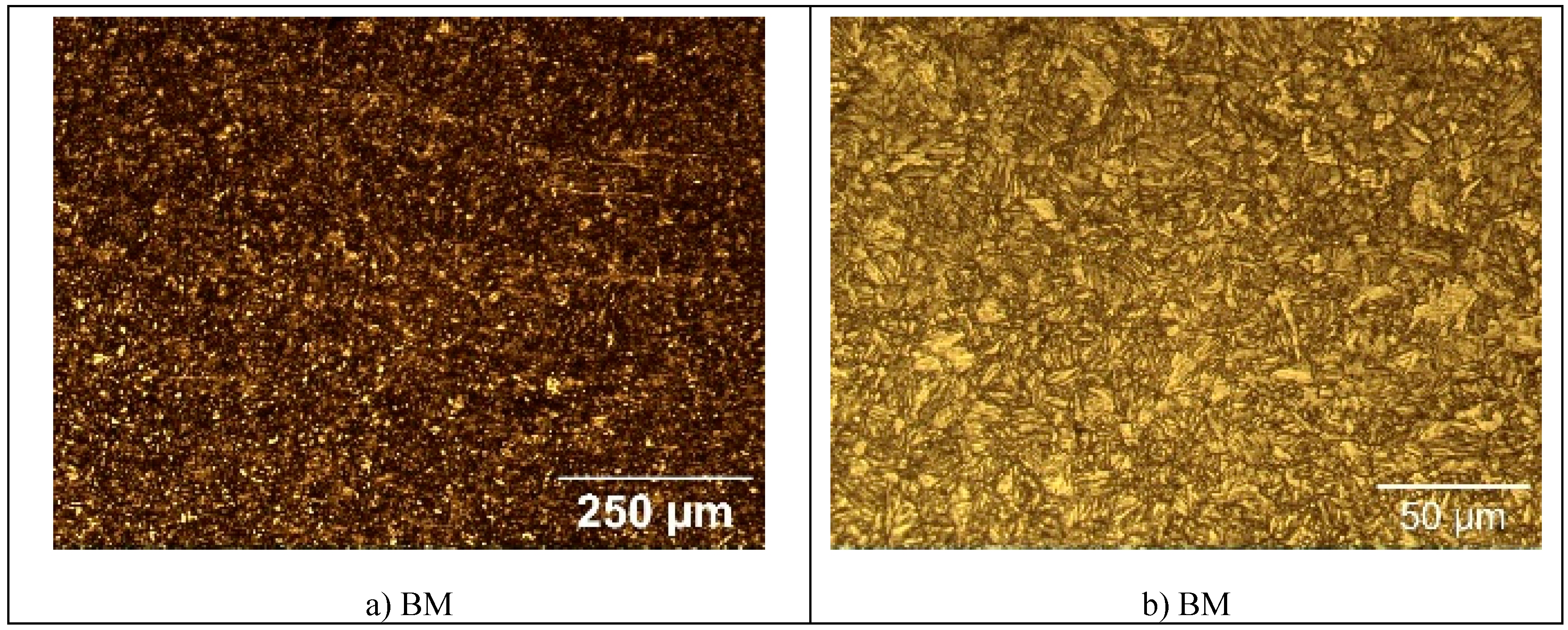
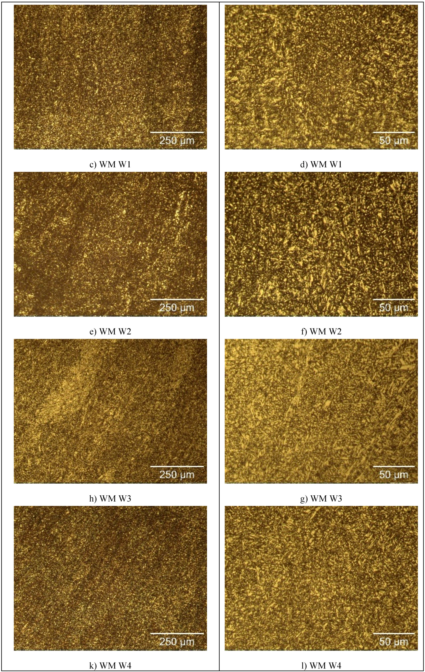
The microstructure of the specimens of S960QL is presented in
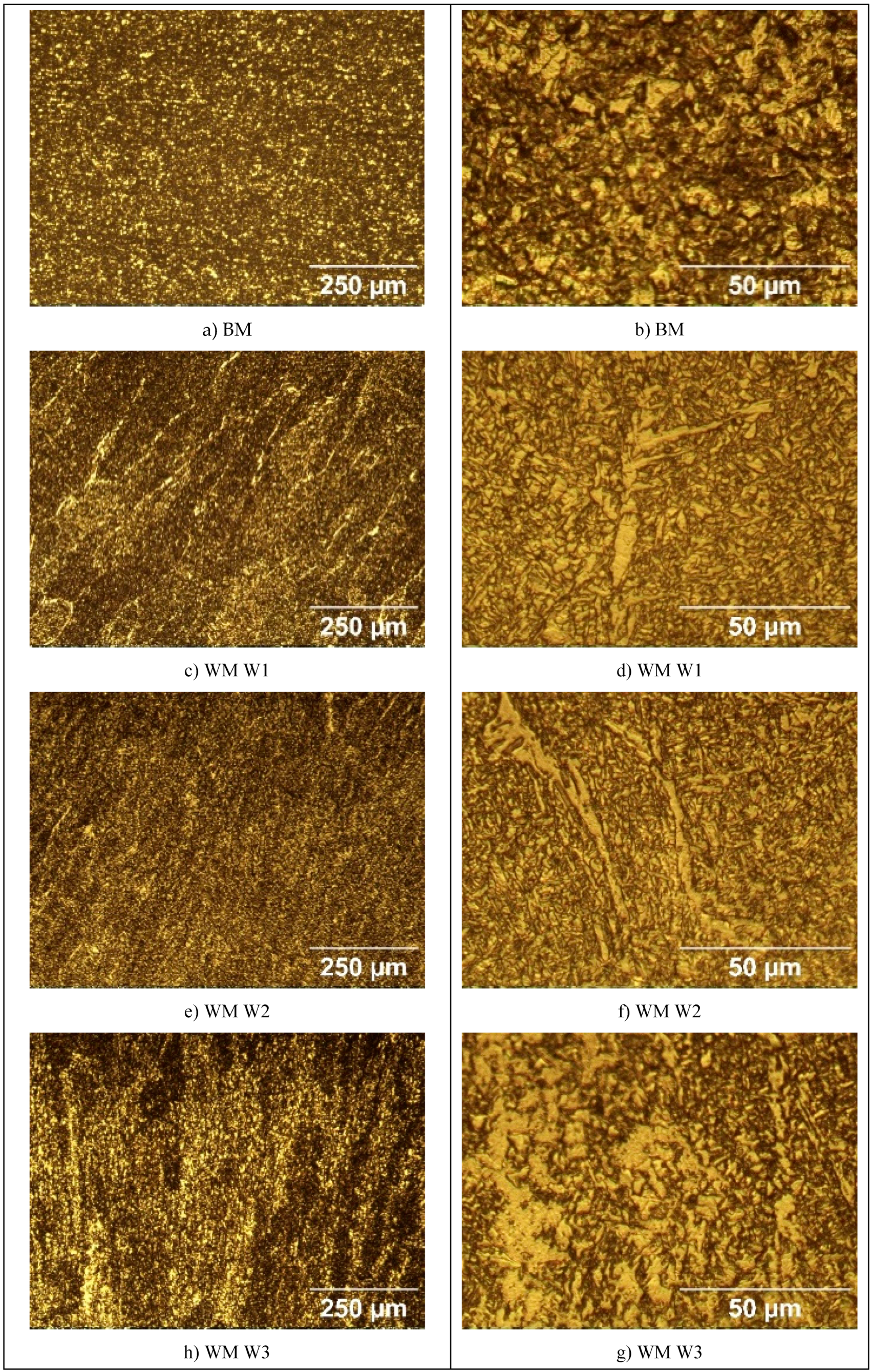
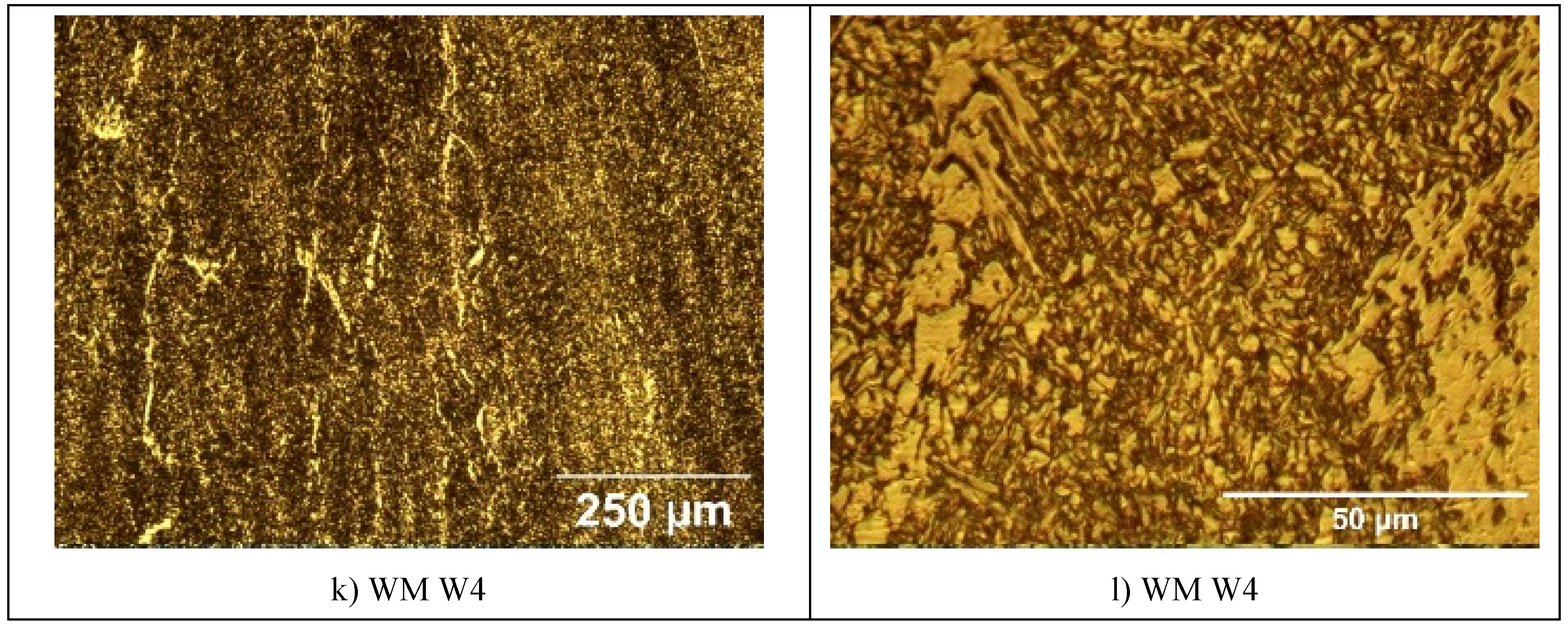
Figure 4, and microstructure of the specimens made of S760MC– in
Figure 5. S960QL steel demonstrates a homogeneously looking microstructure, consisting of tempered martensite and bainite –
Figure 4a and 4b. The microstructure of S700MC steel is composed of ferrite and bainite and shows signs of the thermo-mechanical treatment the steel was subjected to from the manufacturer –
Figure 5a and 5b. The weld metal’s microstructure of all weldments demonstrates a cast structure with a white constituent as elongated grains –
Figure 4 and
Figure 5. This white constituent is ferrite and is larger in share and dimensions in the WM of S700MC than in the WM of S960QL weldments, as visible in
Figure 4 and
Figure 5.
The tested surfaces are shown in
Figure 1. As the opening of the specimens’ holder for corrosion testing was 8 mm and the specimens were centred in the holder, the presented here results give information about the corrosion behaviour only of the weld metal near the centre line of the weldments.
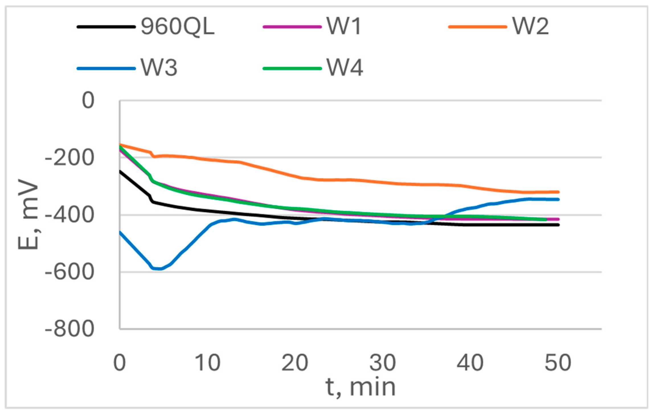
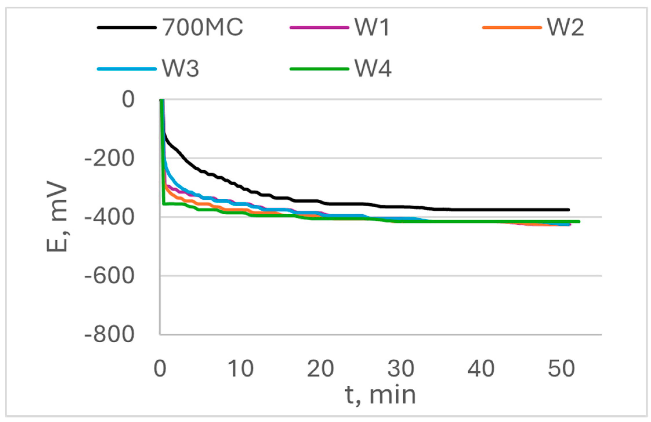
The open circuit potential OCP and its change in time are shown in
Figure 6 for S960QL specimens and in
Figure 7 for S700MC specimens. The values of steady state potential E
ss are summarized in
Table 3. While S960QL demonstrates more negative OCP and E
ss than the weld metal of the weldments of S960QL, S700MC displays a more noble potential than its weldments.
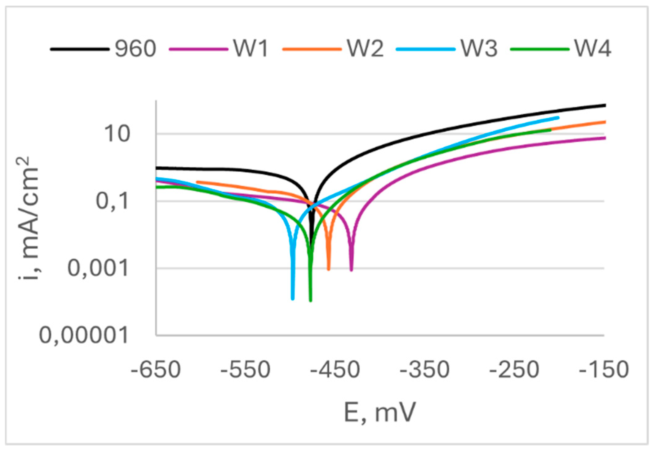
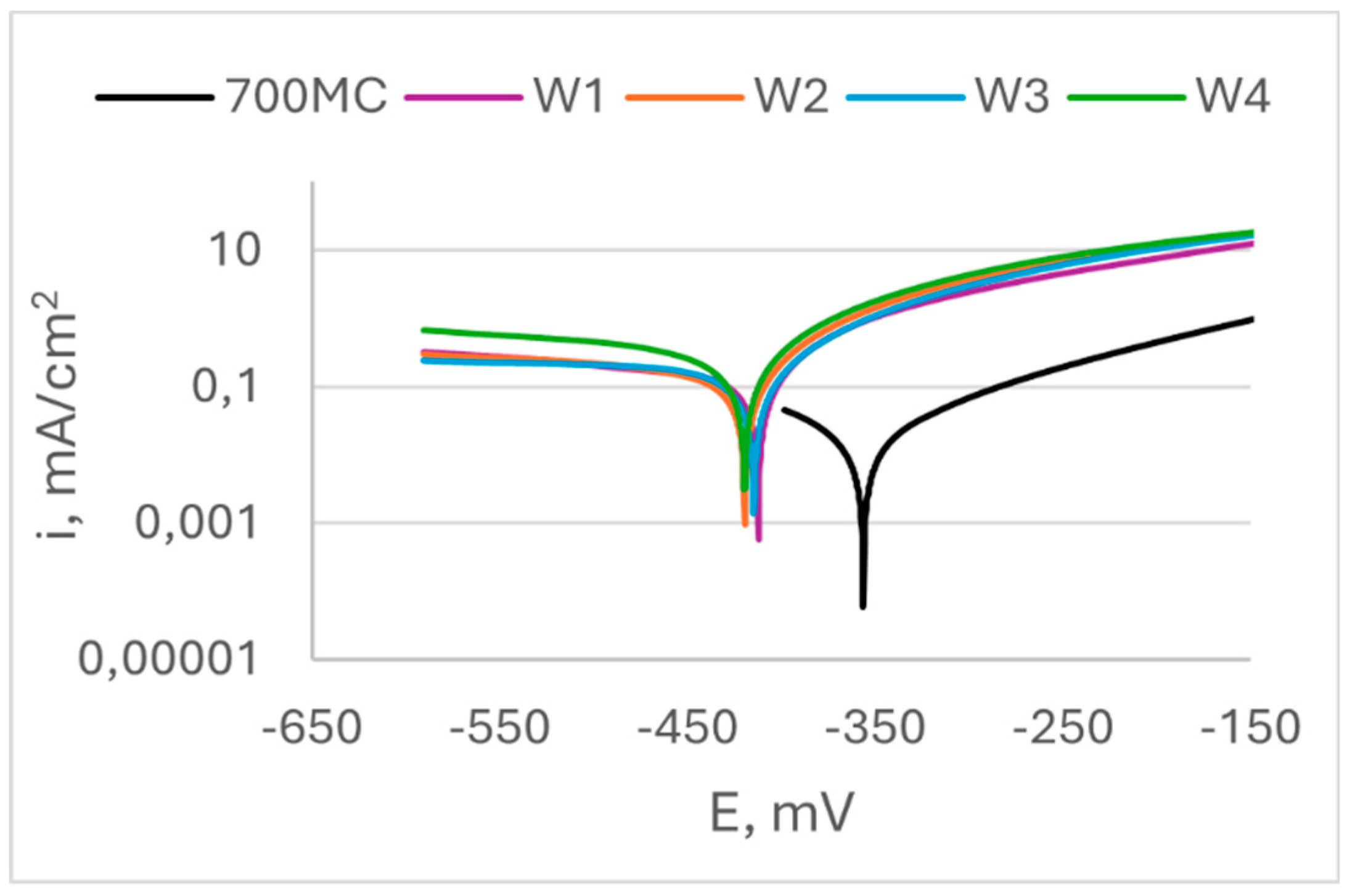
Figure 8 shows results from potentiodynamic scan of specimens of S960QL, and
Figure 9 – of S700MC’s specimens. Corrosion potential E
corr, corrosion current density i
corr and calculated corrosion penetration rates CR are presented in
Table 3. It is seen in
Figure 8 that the weld gap does not categorically influence the corrosion potential of WM on S960QL – the weld metal of weldments made by welding modes W1 and W2 have slightly more positive values of E
corr, while values of corrosion potential of the weld metal of weldments obtained by welding modes W3 and W4 are shifted in negative direction. Nevertheless, corrosion current density, respectively corrosion rate of the weld metal of all weldments of S960QL are lower with one order of magnitude than these of base metal. A different picture is observed for specimens made of S700MC - corrosion potential of the weld metal of all specimens of S700MC is shifted towards more negative values compared to the base metal, and corrosion current density and corrosion rate outweigh the corresponding values for the base metal with one order of magnitude. No local corrosion damage was observed after electrochemical testing but uniform surface dissolution.
4. Discussion
The corrosion behaviour of the weld metal of the studied here weldments should be governed by their structure and the specific corrosion medium. The difference in chemical composition between base metal and weld metal must be taken in account too when discussing practical implications.
The role of medium. Formation of thick stable protective passive layers for both steels in the used neutral solution or in air is not possible so the tested surfaces are unprotected from the action of aggressive ions. As the sodium chloride concentration in the solution is low, oxygen solubility is at its highest levels and there is enough dissolved oxygen to reach cathodic areas on the specimens’ surfaces and corrosion process to takes place without an effective diffusion - barrier film to prevent the anodic dissolution of the specimens [21]. Thus, one can expect that the main factors controlling the dissolution of the specimens are their structure and chemical composition.
The role of structure and chemical composition. It is described in [22] that the addition of Ni in a medium carbon ultra-high strength steel leads to a decrease in the corrosion rate. This effect is profound up to 0.5 wt.% Ni and the next increase up to 1 wt.% in Ni content only slightly decreases the corrosion rate but open circuit potential increases consistently with Ni addition in an acid medium. The beneficial effect of Ni on the corrosion rate of medium-carbon steel in a neutral NaCl aqueous solution is attributed to the formation of a thin, rich in Ni layer under the outer layer of iron oxides [22].
S960QL and S700MC have both a bainite constituent but S700MC base metal also reveals an equilibrium constituent – ferrite grains, while the microstructure of S960QL base metal is entirely non-equilibrium: tempered martensite and bainite. Despite the higher concentration of Ni and Cu in S960QL, this non-equilibrium microstructure and the micro-stresses connected to it led to the higher corrosion rate of S9600QL compared to S700MC base metal.
The weld metal was characterized by a dendritic structure but due to the directional crystallisation, opposite to heat output, the grains on all tested surfaces of weld metal showed almost equiaxed shape. The microstructure of weld metal of S700MC specimens was characterized by a larger amount of idiomorphic ferrite. According to [23], idiomorphic ferrite in weld metal forms when non-metallic inclusions, mostly oxides, serving as nucleation sites for heterogeneous nucleation of ferrite, are present in the weld metal. This indicates that oxygen in larger amount entered the weld pool during welding. The presence of idiomorphic ferrite was more pronounced for weldments of S700MC obtained by welding modes W3 and W4, but it did not affect the corrosion behaviour of weld metal, as it is visible in
Figure 7,
Figure 9 and
Table 4.
The Ni concentration in S960QL was 0.039 wt.%, and in the filler metal – 2.20 wt.%, i.e. more than 56 times higher. The real cooling rates during welding did not allow a significant diffusion of Ni atoms toward base metal, thus leaving nickel concentration highest in the weld metal. On the non-equilibrium phase transformation following crystallization, most of Ni atoms remained locked in martensite and retained austenite, and some of them – in the newly formed ferrite. As the weldments were not subjected to heat treatment, the structural stresses in the weld metal were higher than these in the base metal. Thus, the corrosion behaviour of weld metal of weldments of S960QL was a result of two opposing phenomena: 1) a local enrichment of weld metal in Ni, decreasing the corrosion rate and 2) high level of structural stresses, increasing corrosion rate. As it is visible in
Figure 6,
Figure 8, and
Table 4, none of these phenomena prevails when only OCP, E
ss and E
corr are considered but obviously the above-mentioned rich in Ni layer led to some protection of the weld metal and the corrosion rate decreased.
The weld metal of weldments of S700MC showed worsening in corrosion behaviour compared to base metal. Apparently, the chemical composition of filler material did not work to keep the corrosion potential and steady state potential unchanged. The electrochemical reaction on weld metal’s surface occurred with cathodic control as the steady state and corrosion potentials of weld metal were close to the standard electrode potential of pure iron. Nevertheless, both anodic and cathodic current densities of weld metal of S700MC specimens were higher than these of base metal. Thus, the non-equilibrium microstructure of weld metal was the factor, which controlled the corrosion behaviour of weld metal of S700MC samples, and it resulted in greater corrosion rates of weld metal.
For the weld metal of all weldments of both steels, welding gap did not affect the corrosion behaviour.
As the steady state and corrosion potentials of the weld metal of all weldments of S700MC were shifted in a negative direction, the appearance of a corrosion galvanic cell could be expected with the weld metal acting as an anode, and the base metal – as a cathode. Since the potential difference between the base metal and weld metal is not so pronounced (40 to 50 mV), the resulting current should not have high values. Nevertheless, the base metal surpasses the weld metal in area, i.e. base metal represents a cathode consuming a considerable number of electrons. Thus, in real working environments that promote corrosion processes, a high corrosion rate and dissolution of weld metal is to be expected.
The appearance of a corrosion galvanic cell is expected for specimens of S960QL too but in this case the role of anode and cathode could not be categorically specified. Despite this, preventive measures should be considered when employing weldments of S960QL and S700MC, and the practical one is corrosion protection painting.
5. Conclusions
The results, presented in this work, focus on corrosion behaviour of weld metal. Although the weldments consist of more zones than a weld metal and to completely characterise them future research must be done, the presented here experiments add toward the scarce information about the corrosion behaviour of weldments of high-strength steels.
The practical conclusion about the influence of the width of the welding gap on the corrosion behaviour of weld metal is that when designing welding modes, no consideration with respect to corrosion is needed, as the width of the welding gap does not affect corrosion behaviour of weld metal of weldments of S960QL and S700MC in 3.5% NaCl aqueous solution.
The corrosion behaviour of the weld metal depends on its microstructure and the chemical composition of filler materials, and none of these two factors always prevails. Thus, the filler material for welding of S960QL leads to a decrease in corrosion rate of the weld metal despite its non-equilibrium microstructure, but the corrosion behaviour of the weld metal of weldments of S700MC is governed by its non-equilibrium microstructure and the filler material does not affect it in 3.5% NaCl aqueous solution.
For practical purposes, corrosion prevention of weldments of S960QL and S700MC with paints is recommended.
Author Contributions
Conceptualization, M.I., N.F.; methodology, M.I., N.F.; microstructural analysis, M.I and D.G.; corrosion analysis, M.I.; investigation, M.I., D.G.; software, M.I.; validation, M.I.; resources, N.F., D.G and R.R.; writing—original draft preparation, M.I; writing—review and editing, M.I., D.G.; visualization, M.I. All authors have read and agreed to the published version of the manuscript.
Funding
This study is financed by the European Union-NextGenerationEU, through the National Recovery and Resilience Plan of the Republic of Bulgaria, project № BG-RRP-2.013-0001-C01
References
- M. Tümer, C. Schneider-Bröskamp and N. Enzinger, “Fusion welding of ultra-high strength structural steels – A review,” Journal of Manufacturing Processes, vol. 82, pp. 203-229, 2022. [CrossRef]
- W. S. Association, “Steel’s contribution to a low carbon future and climate resilient societies - worldsteel position paper,” 2019.
- R. P. Sisodia and M. Gáspár, “Experimental assessment of microstructure and mechanical properties of electron beam welded S960M high strength structural steel,” Manufacturing Letters, vol. 29, pp. 108-112, 2021. [CrossRef]
- L. Zhang and T. Kannengiesser, “Austenite grain growth and microstructure control in simulated heat affected zones of microalloyed HSLA steel,” Materials Science and Engineering: A, vol. 613, pp. 326-335, 2014. [CrossRef]
- J. Sun and K. Dilger, “Influence of preheating on residual stresses in ultra-high strength steel welded components,” Journal of Materials Research and Technology, vol. 25, pp. 3120-3136, 2023. [CrossRef]
- J. Gorka and . A. Kotarska, “MAG welding of 960QL quenched and tempered steel,” in IOP Conference Series: Materials Science and Engineering, 2019. [CrossRef]
- M. Türker, “The Effect of Welding Parameters on Microstructural and Mechanical Properties of HSLA S960QL Type Steel with Submerged Arc Welding,” Journal of Natural and Applied Sciences, vol. 21, no. 3, pp. 673-682, 2017. [CrossRef]
- T. Szymczak, B. Szczucka-Lasota, T. Węgrzyn, B. Łazarz and A. Jurek, “Behavior of Weld to S960MC High Strength Steel from Joining Process at Micro-Jet Cooling with Critical Parameters under Static and Fatigue Loading,” Materials, vol. 14, no. 11, 2021. [CrossRef]
- I. Garašić, A. Ćorić, Z. Kožuh and I. Samardzic, “Occurrence of cold cracks in welding of high-strength S960 QL steel,” Tehnicki Vjesnik-technical Gazette, vol. 17, no. 3, pp. 327-335, 2010.
- R. P. S. Sisodia and M. Gáspár, “An Approach to Assessing S960QL Steel Welded Joints Using,” Metals, vol. 12, 2022. [CrossRef]
- T. Sl˛ezak, “Fatigue Examination of HSLA Steel with Yield,” Metals, vol. 10, 2020. [CrossRef]
- W. Guo, D. Crowther, J. A. Francis, A. Thompson , Z. Liu and L. Li, “Microstructure and mechanical properties of laser welded S960 high,” Materials and Design, vol. 85, p. 534–548, 2015. [CrossRef]
- T. Kik, J. Górka, A. Kotarska and T. Poloczek, “Numerical Verification of Tests on the Influence of the Imposed Thermal Cycles on the Structure and Properties of the S700MC Heat-Affected Zone,” Metals, vol. 10, 2020. [CrossRef]
- J. Moravec, J. Sobotka, I. Novakova and S. Bukovska, “Assessment the Partial Welding Influences on Fatigue Life of S700MC Steel Fillet Welds,” Metals, vol. 11, 2021. [CrossRef]
- B. Skowrońska, T. Chmielewski, D. Golański and . J. Szulc, “Weldability of S700MC steel welded with the hybrid plasma + MAG method,” Manufacturing Review, vol. 7, no. Special Issue – Advanced Joining Processes, 2020. [CrossRef]
- N. Ferdinandov, D. Gospodinov, M. Ilieva and R. Radev, “Structure and Mechanical Properties of High Strength Steel 960QL Weldments,” Defect and Diffusion Forum, vol. 416, pp. 93-101, 2022. [CrossRef]
- N. Ferdinandov, G. Danail, M. Ilieva and R. Radev, “Effect of the Root Gap on the Structure and Properties of High Strength Steel S700MC Welds,” Key Engineering Materials, vol. 890, pp. 201-208, 2021. [CrossRef]
- Nasa, “Salinity,” [Online]. Available: https://salinity.oceansciences.org/overview.htm#:~:text=On%20average%2C%20sea%20surface%20salinity,and%20ice%20freezing%20and%20melting. [Accessed 19 06 2024].
- J. Hrbac, V. Halouzka, L. Trnkova and J. Vacek, “eL-Chem Viewer: A Freeware Package for the Analysis of Electroanalytical Data and Their Post-Acquisition Processing,” Sensors, vol. 14, no. 8, pp. 13943-13954. [CrossRef]
- A. G102, G 102 – 89 Standard Practice for Calculation of Corrosion Rates and Related Information from Electrochemical Measurements, ASTM, 1999.
- R. W. Revie and H. H. Uhlig, Corrosion and corrosion control : an introduction to corrosion science and engineering, 4 ed., John Wiley & Sons, Inc. , 2008.
- H. Mohrbacher and A. Kern, “Nickel Alloying in Carbon Steel: Fundamentals and Applications,” Alloys, vol. 2, no. 1, pp. 1-28, 2023. [CrossRef]
- S. Liu, “Control of chemical composition and microstructure in low carbon microalloyed steel weldments,” in Welding: Theory and Practice, D. Olson, R. Dixon and A. Liby, Eds., Elsevier Science Publishers B.V., 1990, pp. 118-148. [CrossRef]
|
Disclaimer/Publisher’s Note: The statements, opinions and data contained in all publications are solely those of the individual author(s) and contributor(s) and not of MDPI and/or the editor(s). MDPI and/or the editor(s) disclaim responsibility for any injury to people or property resulting from any ideas, methods, instructions or products referred to in the content. |
© 2024 by the authors. Licensee MDPI, Basel, Switzerland. This article is an open access article distributed under the terms and conditions of the Creative Commons Attribution (CC BY) license (http://creativecommons.org/licenses/by/4.0/).
