.1. Introduction
MIMO systems are essential for enhancing spectral efficiency in modern wireless networks. Spatial multiplexing in MIMO systems allows for simultaneous transmission of multiple information streams across different antennas, setting it apart from diversity systems that focus on reliability by transmitting identical information. Achieving higher data rates through spatial multiplexing presents significant challenges at the receiver, particularly in detection complexity and efficiency, which have been the subject of research for over five decades, driving the evolution of MIMO detection methodologies [
1,
2]. The core of MIMO detection involves decoding transmitted symbols using known channel characteristics. While maximum likelihood (ML) detection minimizes bit error rate (BER) optimally, it is computationally impractical for physical implementations involving large number of antennas. Therefore, alternative methods like sphere decoding (SD), zero forcing (ZF), and linear minimum mean squared error (LMMSE) have been developed for near-optimal performance with lower complexity [
2]. There are also methods such as Neumann series expansion (NSE), Gauss-Seidel (GS), and Conjugate Gradient (CG) which utilize iterative matrix-vector multiplication to reduce system complexity [
3,
4,
5,
6]. Non-linear MIMO detectors are useful in reducing interference for subsequent signals, though errors in interference signals can degrade detection efficacy [
7]. Advanced approaches, such as the Belief Propagation (BP) algorithm [
8], are effective for high number of antennas and low inter-channel correlation, but may introduce delays and degrade performance in fading channels due to their iterative nature. Therefore, developing a detection strategy that achieves high reliability without requiring excessive amount of decoding time is one of the major challenges in MIMO systems [
9].
In addition to conventional methods discussed above, recent studies have explored both model-driven and data-driven deep learning approaches [
10]. Model-driven techniques enhance iterative algorithms like orthogonal approximate message passing (OAMP) [
11], alternating direction method of multipliers (ADMM) [
12], Viterbi [
13], expectation propagation [
14]. Data-driven solutions use deep learning architectures such as autoencoders [
15], DNNs, and convolutional neural networks (CNNs) [
16] for high detection accuracy. These DL-based MIMO detection methods outperform traditional detectors under various channel conditions. Although there are studies that either discuss model-driven and data-driven approaches separately or together, the increasing amount of data in new communication systems increasingly favours model-driven methods. Unsupervised deep learning techniques, such as autoencoders, can be used to learn the entire system for MIMO detection, as demonstrated in data-driven MIMO detection [
15]. In addition, DetNet uses a model-driven approach to detection using iterative projected gradient descent [
17]. Data-driven methods for MIMO detection in fixed-channel scenarios utilize CNNs and DNNs [
16]. Another approach uses conventional deep learning network topologies for signal detection in MIMO systems with erroneous channels [
18], while another study employs neural networks to identify decision zones for multi-user MIMO systems [
19].
Deep unfolding algorithms, also known as model-driven deep learning methods, constitute a transformative approach that combines classical iterative methods with the adaptive capabilities of neural networks, are a common solution for MIMO detection [
20,
21]. By structuring known iterative algorithms into neural network layers, each iteration treated is treated as a layer [
22] that allows parameter to be trained via backpropagation rather than updated deterministically in a traditional way. This leads to improved solutions by incorporating additional or modified parameters to capture features that classical methods may miss [
23]. Unlike traditional methods, the network can generalize to new inputs after training on different data sets, eliminating the need to recalculate parameters for each system change. This approach builds neural network layers over multiple iterations using advanced learning techniques to achieve unprecedented results [
20,
24,
25,
26]. Various deep unfolding-based algorithms for MIMO channel detection are reported, including trainable projected gradient detectors [
27] and the conjugate gradient descent technique [
28,
29], with other examples in [
11,
12,
30]. Despite these developments, there is still a significant research gap in improving these approaches, especially when it comes to dealing with the complexity and variability of harsh situations. This emphasises the need for further advances in this area and the usefulness of the proposed approach in improving MIMO detection technology.
Deep unfolding approach also offers significant advantages in computational efficiency and hardware implementation [
26]. This method is particularly beneficial for physical applications with hardware constraints and operational efficiency requirements. By predetermining the neural network's structure to mimic specific algorithm iterations, it reduces the need for extensive training data and computational resources, addressing major challenges faced by traditional deep neural networks (DNNs). Deep unfolding enables the pre-design of general-purpose circuits quickly adaptable through trained neural networks, significantly reducing the time from algorithm design to market deployment.
This study presents a significant advance in the field of MIMO signal detection by introducing a unique detection strategy that combines Tikhonov regularization and CG method with deep unfolding. Using the matrix L as a regularization term enhances the detection process and allows for significant improvements over conventional methods for different channel conditions and antenna layouts. The main contributions of this study are summarized below:
To the best knowledge of authors, this is the first study that Tikhonov regularization is integrated with the conjugate gradient method for MIMO detection in a deep learning based approach.
Performance of the proposed method has been compared with both iterative and model-driven techniques for different channel models such as Rayleigh, Kronecker, TDL-A, and TDL-E.
The remaining sections of this study are organized as follows:
Section 2 presents the relevant work and subjects.
Section 3 provides a thorough explanation of the proposed approach. The simulation results are given in
Section 4 and in
Section 5, conclusions are drawn, and suggestions for further work are explored.
2. Materials and Methods
2.1. MIMO System Model
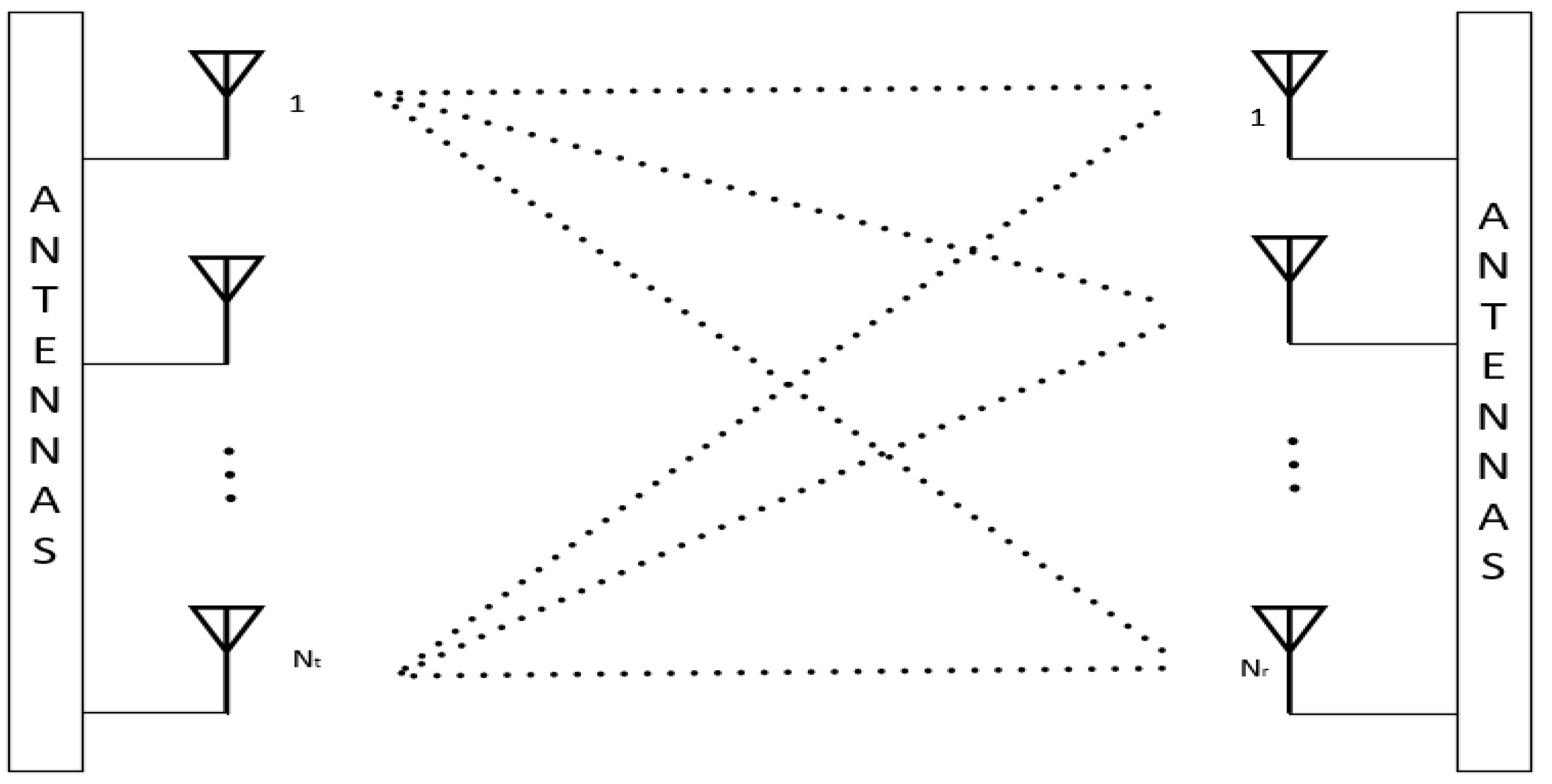
In this study, we investigate a MIMO system utilizing spatial multiplexing, wherein the receiver antennas concurrently receive symbols transmitted from the transmitter. The system comprises
receiving antennas and
transmitting antennas as shown in Fig 1. The received symbols, denoted as
, at the receiver side can be expressed as follows:
In the aforementioned equation (1), denotes the entries of the channel matrix corresponding to the communication link between the -th transmitter antenna and the -th receiver antenna. The term signifies the additive white Gaussian noise (AWGN) present at the-th receiver antenna, characterized by zero mean and variance. ,, represent complex-valued numbers, and signify complex-valued channel which is assumed to exhibit flat Rayleigh fading, with the channel entries, , being independently and identically distributed (i.i.d) with zero mean and unit variance.
The matrix
H and the vectors
y, s, n have complex values, due to the necessity of using real numbers in the deep learning structure, the MIMO channel model is expressed as follows for the simulation environment within the scope of the study:
MIMO system's simplified block diagram is shown in
Figure 1. Multiple antennas are used in this system, both at the transmitter and receiver ends.
The numerous signal routes between the antennas are depicted in the
Figure 1 by connecting each transmitting antenna to each receiving antenna. Through the use of spatial diversity and the ability to transmit many data streams at once, this arrangement improves the capacity and dependability of the system. The intricate interaction and signal propagation in a MIMO system are highlighted by the dotted lines.
2.2. MIMO Channel Model
MIMO channels are critical to today's modern communication systems. These systems can significantly improve transmission rate, reliability, and spectrum efficiency by using multiple antennas at both the transmitter and receiver. Each element in the matrix characterizing the MIMO channel represents the channel coefficient between a given pair of transmit and receive antennas. The effects of multipath propagation are well captured by this matrix, which is important for understanding and improving the functionality of advanced communication networks. A Rayleigh channel in MIMO systems is a model in which Rayleigh fading affects the channel coefficients. This phenomenon happens when there is no direct line-of-sight path and multipath propagation, causing changes in the signal's magnitude. Usually, the model for each element of the MIMO channel matrix
is an independent, identically distributed (i.i.d.) complex Gaussian random variable with unit variance and zero mean. This is the result of multiple tiny reflections from various pathways coming together to create a fading envelope that has a Rayleigh distribution. The Rayleigh channel model works well in indoor or urban settings where there are lots of impediments scattering the signal. It functions as a foundational model for analyzing the capacity and performance of MIMO systems in practical multipath scenarios. A mathematical framework used in MIMO systems to make it easier to characterize spatial correlations between antennas at the transmitter and receiver is called the Kronecker channel model [
31]. According to the model, transmit and receive correlation matrices at each end correspond to separable correlation structures that can be formed from the overall channel matrix. The mathematical expression for this model is:
where and are the Cholesky decompositions of the receiver and transmitter correlation matrices, respectively, and is an uncorrelated Rayleigh fading matrix.
The simplicity and mathematical tractability of the Kronecker model are its main features, making it a useful tool for assessing MIMO system performance. In 5G cellular systems, TDL (Tapped Delay Line) channel models - such as TDL-A and TDL-E - defined by 3GPP simulate multipath propagation [
32]. The Tapped Delay Line A (TDL-A) channel model uses a tapped delay line structure to simulate realistic time-varying and frequency-selective scenarios. The taps represent discrete paths with unique delays and power levels. The TDL-A model, which is widely used to simulate urban environments, pre-calculates the channel impulse response to facilitate the assessment of system performance in terms of signal fading and inter-symbol interference (ISI). The channel model holds great significance in the advancement and assessment of 5G technologies, including massive MIMO and beamforming. It offers valuable perspectives for enhancing communication protocols and algorithms, hence guaranteeing reliable performance in practical situations. As such, the TDL-A paradigm plays an important role in the design and implementation of high-performance 5G networks. On the other hand, the Tapped Delay Line E (TDL-E) channel model is particularly well known for its severe multipath conditions, which represent difficult time-varying and frequency-selective scenarios. These conditions include extended delay spreads and large Doppler shifts. The TDL-E model provides a realistic simulation of harsh urban and suburban environments through the taps, which represent discrete propagation paths with varying delays and power levels. This model is essential for assessing the suitability of advanced 5G technologies for harsh environments, including massive MIMO and beamforming. By predicting the channel impulse response, TDL-E helps to evaluate system performance, particularly in terms of signal fading, ISI and the impact of high mobility on signal integrity. The reliable deployment of next-generation wireless technologies will be supported by the ability of 5G networks to maintain high performance under the most demanding conditions, thanks to its use in the design and testing of robust communication algorithms and protocols.
2.3. Conventional MIMO Detection
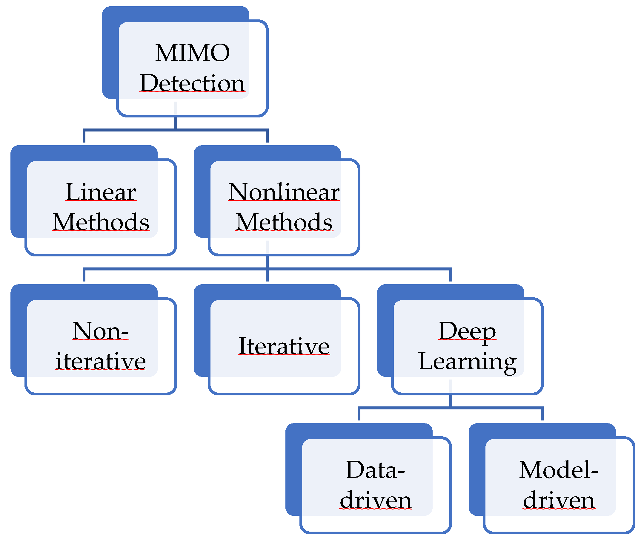
MIMO detectors are simply classified into two categories as linear and non-linear methods. A brief summary of MIMO detection techniques are illustrated in
Figure 2.
As shown in
Figure 2, nonlinear method may be classified into non-iterative, iterative, and deep learning approaches. Additionaly, deep learning based methods encompass both data-driven and deep-unfolded methodologies also called as model-driven.
The earliest studies on the optimum MIMO detectors published in 1976 [
33] which presented a Maximum Likelihood (ML) sequence estimation-based receiver with the objective of reducing Interchannel Interference (ICI) and ISI in multi-channel transmission systems. Research by van Etten demonstrated that this ML receiver could perform almost as well as the optimal receiver in systems without ISI and ICI under specific circumstances [
33]. In systems employing massive MIMO technology, where the transmitter and receiver are equipped with multiple antennas, the utilization of ML for signal detection,
, is not a viable option due to the significant increase in computational load.
The transmitted symbol estimations that are generated by linear MIMO detectors are based on a linear modification of the received signal vector
y. Despite their low computational complexity, their performance is significantly inferior to that of ML detector. In modern communication systems, linear MIMO detection techniques are preferred due to their straightforward methodology and high computing efficiency [
34]. These techniques circumvent the computationally demanding exhaustive search that more sophisticated nonlinear techniques necessitate by decoding signals emitted and received by numerous antennas using straightforward mathematical procedures. These approaches effectively isolate and decode each signal by employing linear algebraic techniques on matrices and vectors that represent the transmitted and received signals. Many communications systems where speed and efficiency are critical consider linear MIMO detection techniques as a viable option due to their balance between performance and computational simplicity. The most potent technique in this group is the Minimum Mean Square Error (MMSE),
, which increases its effectiveness by utilizing both noise variance and channel information.
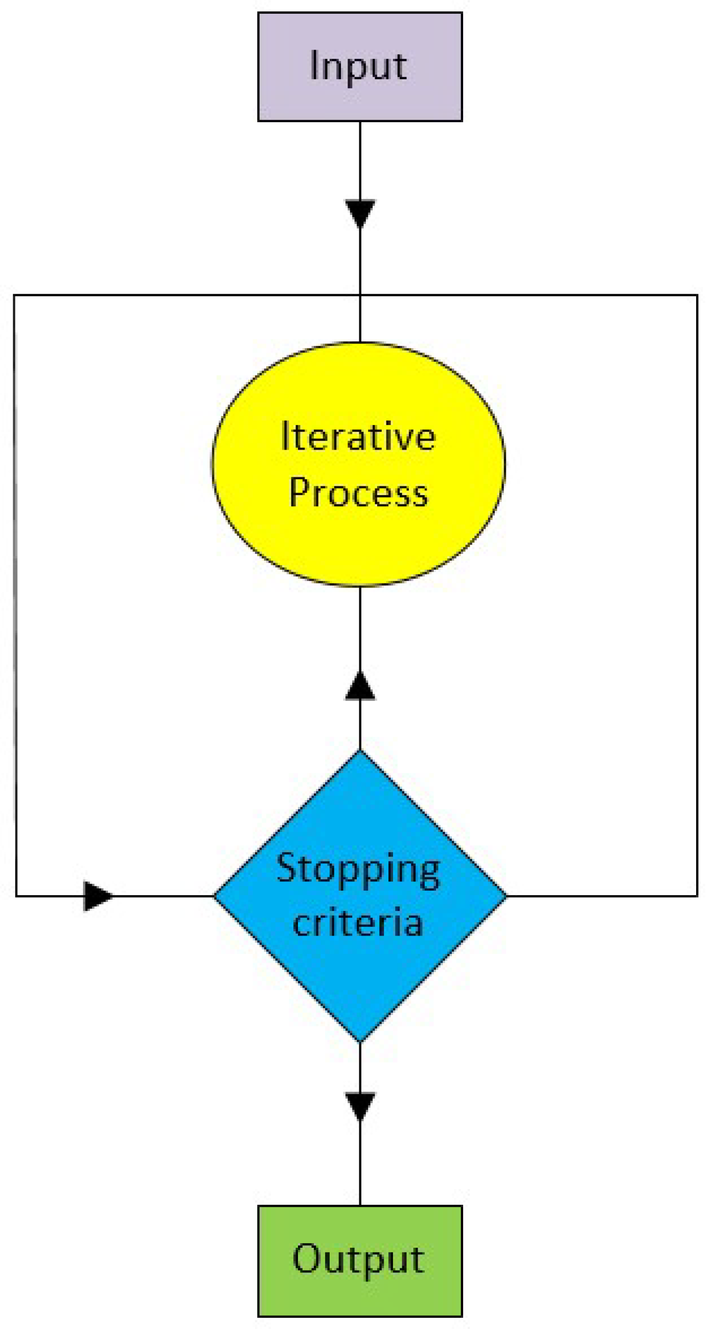
The performance of advanced MIMO wireless communication frameworks are greatly enhanced by non-linear detection approaches, especially in areas of challenging channel conditions. On the other hand, non-linear techniques such as Maximum Likelihood (ML), Belief Propagation (BP), and Sequential Interference Cancellation (SIC) provide more complex computations that can better deal with interference. Iterative methods such as Newton Iteration (NI), Conjugate Gradient (CG), and Sphere Decoder (SD) become crucial as we move towards more complex strategies. These techniques work well by iteratively, as shown in
Figure 3, improving signal estimates, using feedback and previous data to increase detection accuracy without the need for extensive computation.
The Conjugate Gradient (CG) method, introduced by Hestenes and Stiefel in 1952 [
35], is an iterative algorithm for solving systems of linear equations. CG as an iterative method is particularly useful in situations where direct methods are infeasible due to the large dimensions of the matrices involved. This section highlights the CG method's superiority over the Steepest Descent method, demonstrating its efficacy in the context of MIMO detection. The Steepest Descent method minimizes a function
f(
x) by iteratively moving in the direction of the negative gradient −∇
f(
x). This approach continues until convergence is achieved. However, it often suffers from slow convergence, especially in poorly conditioned problems, due to its propensity to zigzag within narrow valleys of the error surface. The CG method starts similarly to the Steepest Descent method by moving in the direction of the negative gradient. However, after the first step, it proceeds in conjugate directions rather than continuing in the steepest descent direction. This strategic adjustment allows the CG method to leverage information from previous iterations, thereby reducing the number of iterations required for convergence. For a linear system
Ax=
b, where
A is a symmetric and positive definite matrix, solving
Ax=
b minimizes the quadratic function:
The gradient condition ∇
f(
x)=0 leads to
Ax−
b=0. This equivalence aligns well with the MIMO channel model, where the goal is to solve for the transmitted signal vector
x given the received signal vector
b and the channel matrix
A. Consequently, the CG method is particularly effective for MIMO systems, offering an efficient and robust solution for signal detection. CG detector’s working principle is summarized in Algorithm 1.
Algorithm 1: MIMO Detection with CG
Output : Transmitted signal vector estimation
1: Initialization:
,
,
2: for i = 0,…,K do
3:
4:
5:
6:
7:
8: end for
9: return |
Algorithm 1 starts with the provided inputs, the channel matrix, the noise variance and the received signal, the algorithm initializes the relevant matrix and vectors. The search direction vector, the residual vector and the solution vector are set first. At each iteration, the solution vector is updated by calculating the step size α, which indicates how far to go in the current search direction. The new solution estimate is then reflected in the residual vector. The algorithm determines a coefficient, β, which modifies the search direction to maintain efficiency in subsequent iterations. This iterative process continues until the desired number of iterations is reached or the solution is sufficiently accurate. The technique, which ultimately provides the estimated transmitted signal vector, effectively solves MIMO detection problems.
2.4. Deep Unfolded MIMO Detection
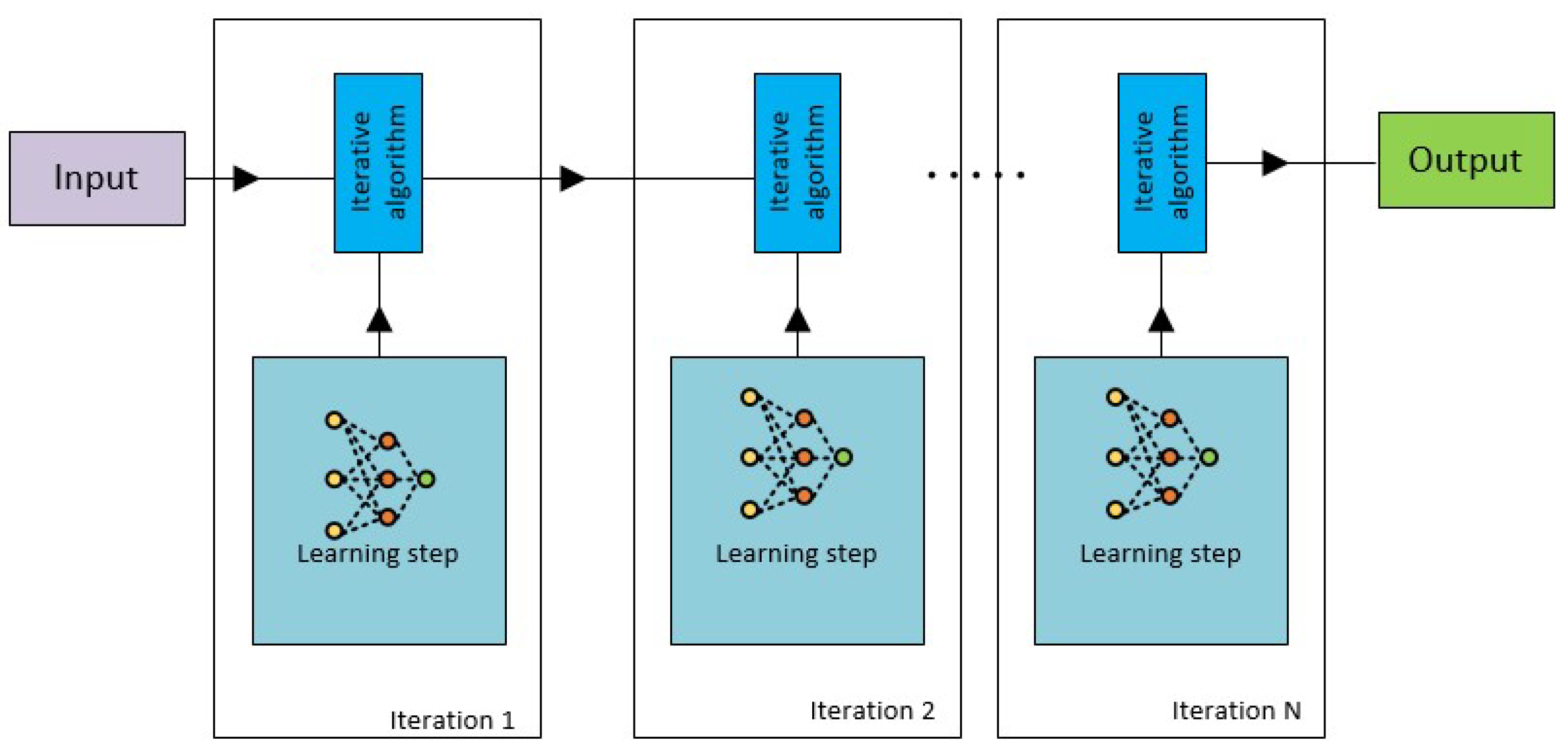
Through the use of deep unfolding technique on iterative detection procedures, deep learning can be applied to MIMO systems. Deep unfolding combines neural networks and conventional signal processing, using domain knowledge to build reliable models. By combining deep learning with conventional signal processing models, deep unfolded MIMO detection,
Figure 4. offers a number of benefits, including improved interpretability for simpler troubleshooting, computational efficiency from fewer parameters, and resilience to changing circumstances. Furthermore, this method, so called deep unfolding, ensures faster convergence, higher generalization within modelled behaviours, and requires less training data, rendering it an optimal solution for situations where computational resources are scarce or when system interpretability is of paramount importance. The most notable achievement in MIMO detection has been the development of deep unfolding techniques, including the sophisticated LCG network and the earlier DetNet, each of which has made a unique contribution to the field.
2.4.1. DetNet
DetNet is the first deep unfolded detection technique, integrating channel data with received signals to handle varying channels [
16]. Unlike data-driven methods, it adapts using projected gradient descent, improving performance in static and Rayleigh fading channels with trainable parameters.
The ReLU function, defined as
, with
, and the soft sign operator
parameterized by
, are used in DetNet.
and
serve as detection statistics. Trainable parameters
are tuned via a loss function. DetNet's performance degrade in large-scale MIMO systems due to high data requirements and complexity [
36].
2.4.2. Learned Conjugate Gradient
Incorporating deep learning techniques to adaptively find the optimal parameters during iterations ensures that the Learned Conjugate Gradient method (LCG) [
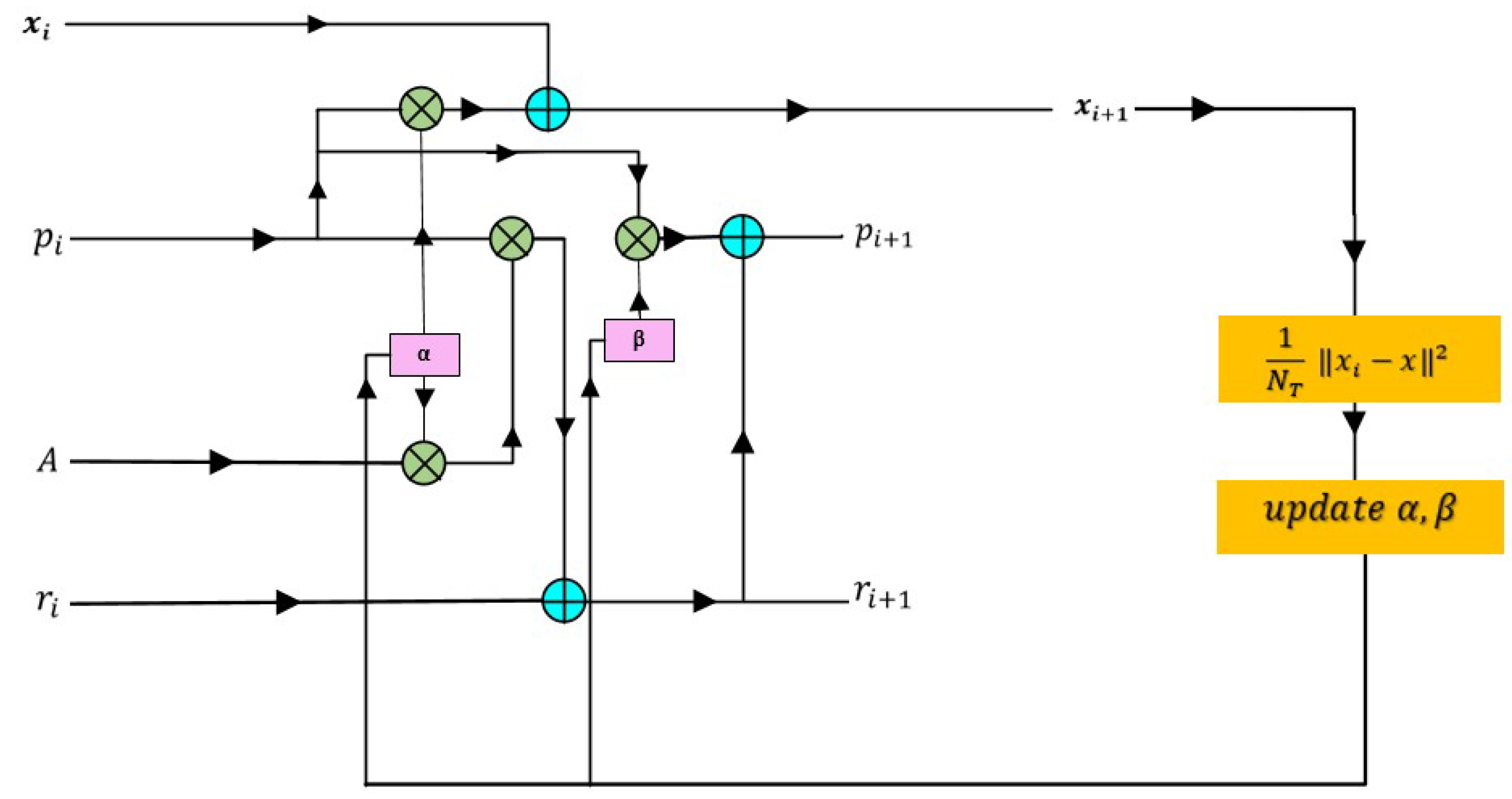
28] has higher performance over the traditional CG method. The LCG method, shown in
Figure 5, modifies the conjugate gradient algorithm by making the step size and search direction coefficient parameters, denoted by α and β respectively, modifiable through training instead of mathematically calculating them on the relevant data sets. The method can now adaptively adjust its step sizes and directions, which enhances detection performance in MIMO systems and facilitates more effective convergence. The limitations of fixed-parameter approaches can be overcome by LCG through the utilization of data-driven insights, thereby providing a robust foundation for the management of the complex and variable conditions of wireless communication channels. As explained in detail in [
28], two types of LCG approaches were introduced namely scalar, LCG-S, and vector, LCG-V. Scalar trainable parameters α and β are used by LCG-S. By eliminating the requirement for matrix-vector multiplications and divisions, these scalar parameters simplify computations. Alternatively, vector trainable parameters
and
are used by LCG-V. These vector step-sizes improve detection performance in complex next-generation communication network scenarios by allowing LCG-V to learn and adapt more effectively to the data characteristics. It is highlighted in the work [
28] that LCG-V requires storing more parameters even though its computational complexity is almost the same as that of LCG-S for its operations.
3. Proposed Method
Tikhonov regularization, also known as ridge regularization, is a method for solving ill-posed problems or preventing overfitting in linear regression. It involves adding a regularization term to the solution. Penalizing the magnitude of the coefficients in the loss functionwe are attempting to minimize is the core idea behind Tikhonov regularization. In its simplest version, Tikhonov regularization penalizes solutions with large magnitudes by adding a regularization term to the objective function being reduced [
37]. The solution is more resilient to varying conditions thanks to this regularization term, which also helps to avoid overfitting. Several applications in engineering and physics lead to the following types of linear least-squares problems:
Matrix
A is of ill-determined rank; that is, its singular values gradually decay to zero without a noticeable gap, and the measured data tainted by an unknown error
of norm constrained by δ > 0 is represented by
. Least-squares problems, also referred to as discrete ill-posed problems, require this kind of matrix. An exact approximation of the minimal norm solution
for the error-free least-squares problem associated with (10) is sought after.
represents the pseudoinverse of Moore–Penrose in this case. Due to the error in
and the clustering of A's singular values near the origin, the solution
of (10) is usually not a reasonable approximation of
. Changing the minimization problem to a nearby problem whose solution is less vulnerable to the error in
is one method to overcome this problem (10). This substitution is sometimes referred to as regularization.
The regularization parameter
> 0 in this case controls how sensitive the solution of (11) is to the error e in
as well as how near the solution is to the target vector
. It is generally known that by substituting an appropriate regularization matrix for the Tikhonov minimization problem (11), it is frequently possible to increase the quality of the
approximation determined by Tikhonov regularization
.
where is a suitable regularization matrix.
The regularization matrix encodes the extra restrictions or previous knowledge about the solution x in (12) and λ is a regularization parameter that governs the trade-off between fitting the data and meeting the regularization term.
The particular problem and the body of prior knowledge at hand determine which regularization matrix
L to use. Adding supplementary constraints or information to the regularization term in generalized Tikhonov regularization can result in more pertinent and accurate solutions to inverse problems. This is especially useful in situations where the standard Tikhonov regularization might not be adequate. However, to get the best results, domain expertise and careful tuning are frequently needed when selecting the regularization matrix
L and regularization parameter
λ. In order to promote desired properties like smoothness, sparsity, or spatial structure, the regularization term in generalized Tikhonov regularization must take into account constraints or prior knowledge about the solution
x. This is made possible by the choice of regularization matrix
L.
L and the parameter
λ work together to balance data fidelity and regularization strength by directly influencing the behavior of the regularization term. The process of choosing
L is critical to obtaining precise and reliable solutions to ill-posed inverse problems since it requires domain-specific knowledge and iterative refinement. This process frequently involves experimentation and model selection techniques to optimize regularization for meaningful solutions [
38].
3.1. Deep Unfolded Tikhonov Regularized Conjugate Gradient Algorithm
We utilize Tikhonov regularization in the CG algorithm to improve performance on different types of channels, addressing issues such as noise sensitivity and ensuring convergence in high-dimensional MIMO systems. The CG technique effectively tackles the complexity of high-dimensional MIMO systems, improving performance and signal estimates when paired with Tikhonov regularization. This integration demonstrates the importance of scalability for future high-speed wireless networks. When incorporated into model-driven MIMO detection frameworks, Tikhonov regularization appears to be an effective method for improving robustness and performance. Tikhonov regularization is a technique for stabilizing the solution of ill-posed problems that involves adding a regularization term to the optimization objective. This method involves adding a term L to the system matrix in the context of MIMO detection. This regularization term improves the robustness and accuracy of the detection process by reducing the effects of noise and bad conditioning in the channel matrix H. In this work, the proposed method is dynamically adjusting the detection strength by the model during training thanks to the trainable parameters regularization matrix L, alpha, and beta. It is noteworthy that, unlike
the original Tikhonov regularization approach shown in (12), which represents the parameters
λ and
L individually, our proposed method combines them into a single matrix
L, which is the product of the scalar
λ and the matrix
L. By treating the multiplication of these elements as a single matrix, the network streamlines the computation and improves the flexibility of the model for different channel conditions. The pseudocode of the proposed method have been shown in Algorithm 2.
Algorithm 2: Tikhonov Regularized Conjugate Gradient Algorithm
Output : Transmitted signal vector estimation
1: Initialization:
,
,
2: for i = 0,…,K do
4:
5:
6:
8:
9: train {}
10:
11: end for
12: return |
The convergence stability and overall detection accuracy of this approach is enhanced by using the trainable regularization matrix
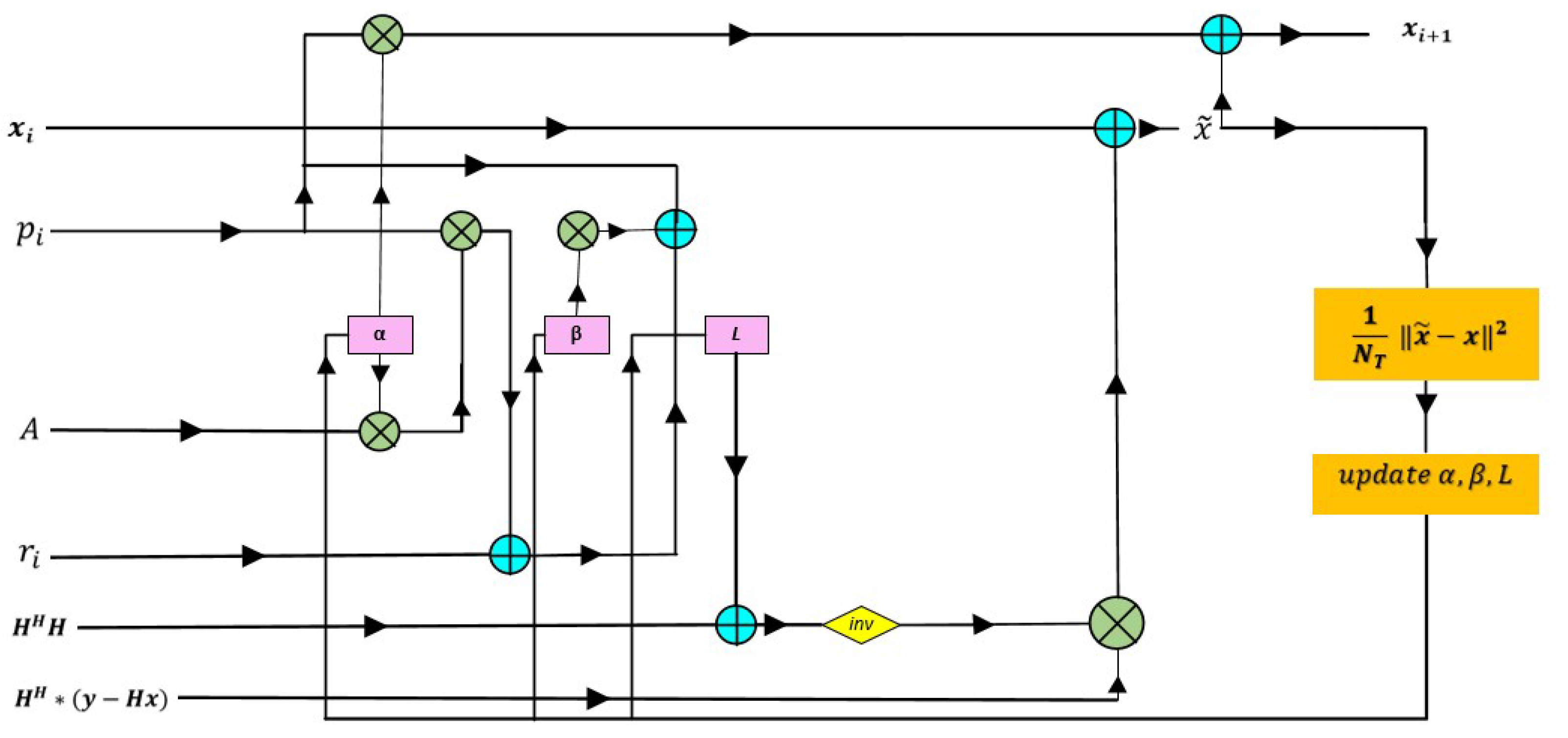
L. This process is tuned to the MMSE criterion, which keeps the detection approach reliable and efficient in challenging situations. The iterations of the Tikhonov-regularized CG algorithm are unrolled to create the proposed Deep Unfolded Tikhonov Regularized Conjugate Gradient (DU-TCG), a deep learning architecture in which each layer is associated with an algorithm iteration as shown in
Figure 6.
Using this method, the model can be trained to find the best parameters for improved performance in a range of channel situations. Along with the α and β parameters, the DU-TCG algorithm adds a new trainable parameter called, the regularization, L which is in matrix form. This combination allows for dynamic modification of the regularization strength during training and simplifies computation as it is processed by the network as a single matrix.
To guide the training process, DU-TCG's loss function is designed to assess the difference between the transmitted signal and the predicted output. For this purpose, the Mean Squared Error (MSE) loss function is used as shown in Algorithm 2. The mean squared difference between the expected and actual values is quantified by the MSE loss function, giving the network a specific target to minimise during training. The network increases the resilience and accuracy of detection by iteratively updating the parameters
α,
β, and
L to minimise this loss.
iteraion of CG algorithm corresponds to the
layer of DU-TCG detector. The layer dependent trainable parameters of DU-TCG detector is represented with
into the i-th layer of the network and learn
and
step size, search direction coefficient and
regularization matrix from training samples
by minimizing mean square error as shown:
L denotes number of layers, denotes output of DU-TCG with and inputs.
This work combines Tikhonov regularization and CG technique with deep unfolding, which significantly improves MIMO signal detection under various MIMO layouts, modulation orders, and channel conditions. The proposed method inserts a regularization term to the system, which improves the stability and generality of the solution. In particular, when there are noisy or imperfect data conditions, this regularization helps the CG converge more consistently. Thus, the approach efficiently handles the complexity present in high-dimensional MIMO systems while iteratively improving its signal estimates.
3.2. Training Details
The TensorFlow library with the Adam optimizer [
39] is used to create the proposed DU-TCG network in Python, and channel matrices are generated using MATLAB. The test and training data sets,
and
, are created randomly based on equation (2) with different noise levels. The transmitted symbols,
x, are chosen from particular modulation schemes such as BPSK and 16-QAM. Different channel models, like the Kronecker channel [
28], Rayleigh fading channel, and TDL-A, TDL-E MIMO channels [
29], have different random generators for their channel matrices. The transmitted symbols,
x’s, are selected from specific modulation schemes including BPSK and QAM16. Different channel models such as Kronecker channel, Rayleigh fading channel, TDL-A, and TDL-E MIMO channels have different random generators for the channel matrices. The training process uses
samples with an SNR of
. In order to increase the robustness of the detector to noise, descending SNR values were included in the training process, although no significant performance improvement was observed. All trainable parameters are initially set to zero. Subsequently,
samples are used for training with SNR values ranging from
to
, incremented by
2 . This wider range of SNR values allows a comprehensive evaluation of the detector's performance. The learning rate is first set to
and is fine-tuned by halving it after each epoch, so that the detection is more robust. The average loss's point of discontinuity determines the stopping criterion. Also, to ensure a fair comparison under identical conditions, the number of layers used in deep unfolded methods was chosen as the same. The training method is computationally efficient, taking about two hours on a normal Intel i7-7500U processor, because the model has just three trainable parameters and works well with a small number of layers. It is anticipated that the training time will rise in proportion to larger MIMO systems or models with more trainable parameters.
4. Simulation Results
Within this section several MIMO layouts over different channel conditions and modulation orders are discussed to demonstrate the performance of the proposed DU-TCG detection method. In particular, the simulation results highlights the detection performance improvement of the DU-TCG over well-known approaches such as the MMSE, CG, and LCG. Unless otherwise stated, BPSK modulation is used for the sake of simplicity. Bit error rate (BER) and normalized mean square error (NMSE) metrics are employed to illustrate the superiority of the proposed method over the discussed other methods.
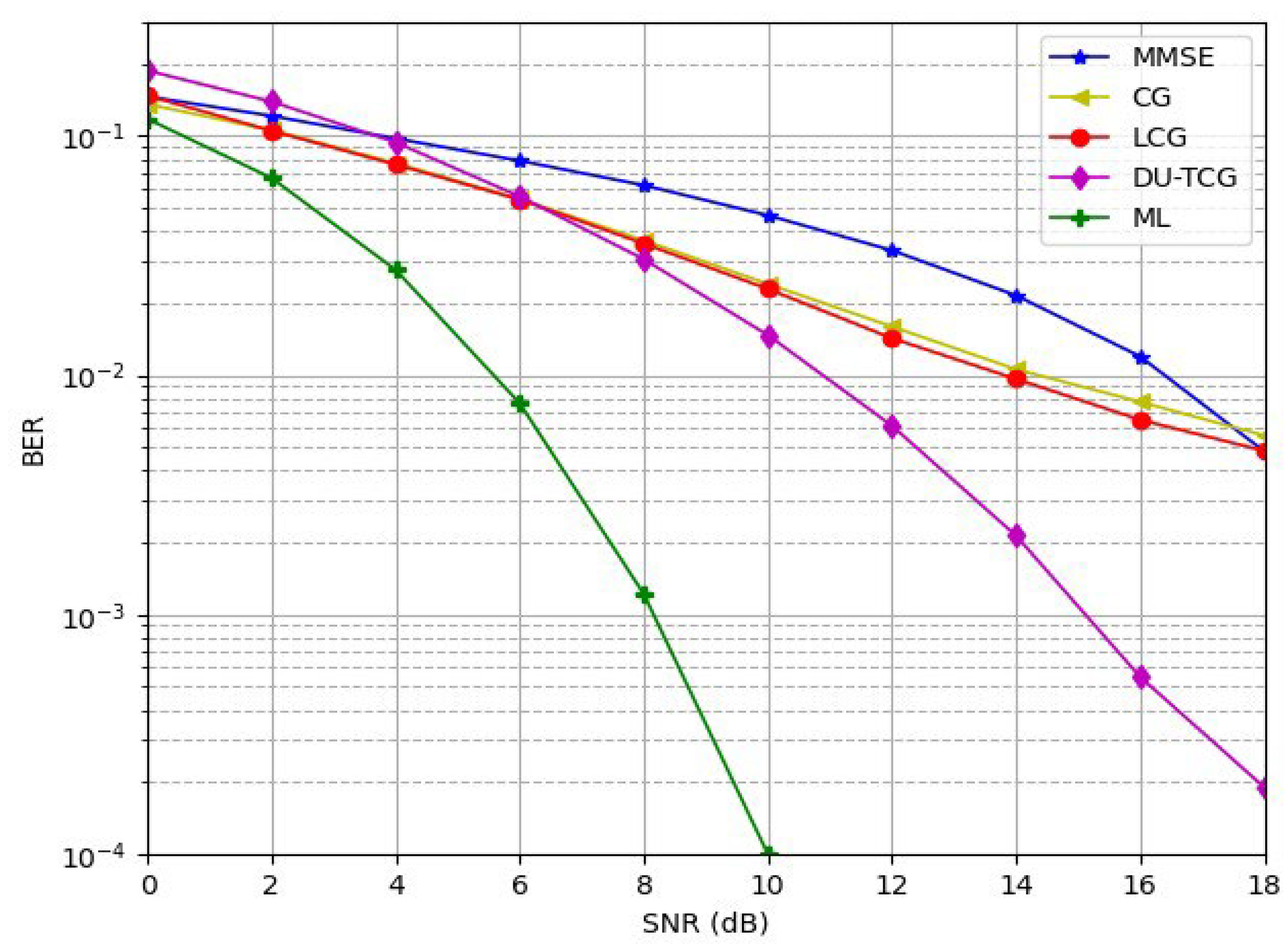
Figure 7 compares the BER performance of the propoposed DU-TCG method with other methods, namely MMSE, CG, LCG, and ideal ML detector over a Rayleigh fading channel for a BPSK modulated 10x10 MIMO system.
Figure 7 shows that although the ML detector offers the lowest bit error rates, proposed DU-TCG can perform better than other gradient-based techniques such as MMSE, CG, and LCG which makes it a promising candidate for practical applications. The proposed DU-TCG method has approximately 4 dB SNR gain over CG and LCG methods at BER values of
. Since DU-TCG can guarantee high-quality detection while maintaining reasonable computational requirements compared to ML detection, it is believed to be well suited for next-generation wireless networks, where efficiency and performance must be balanced.
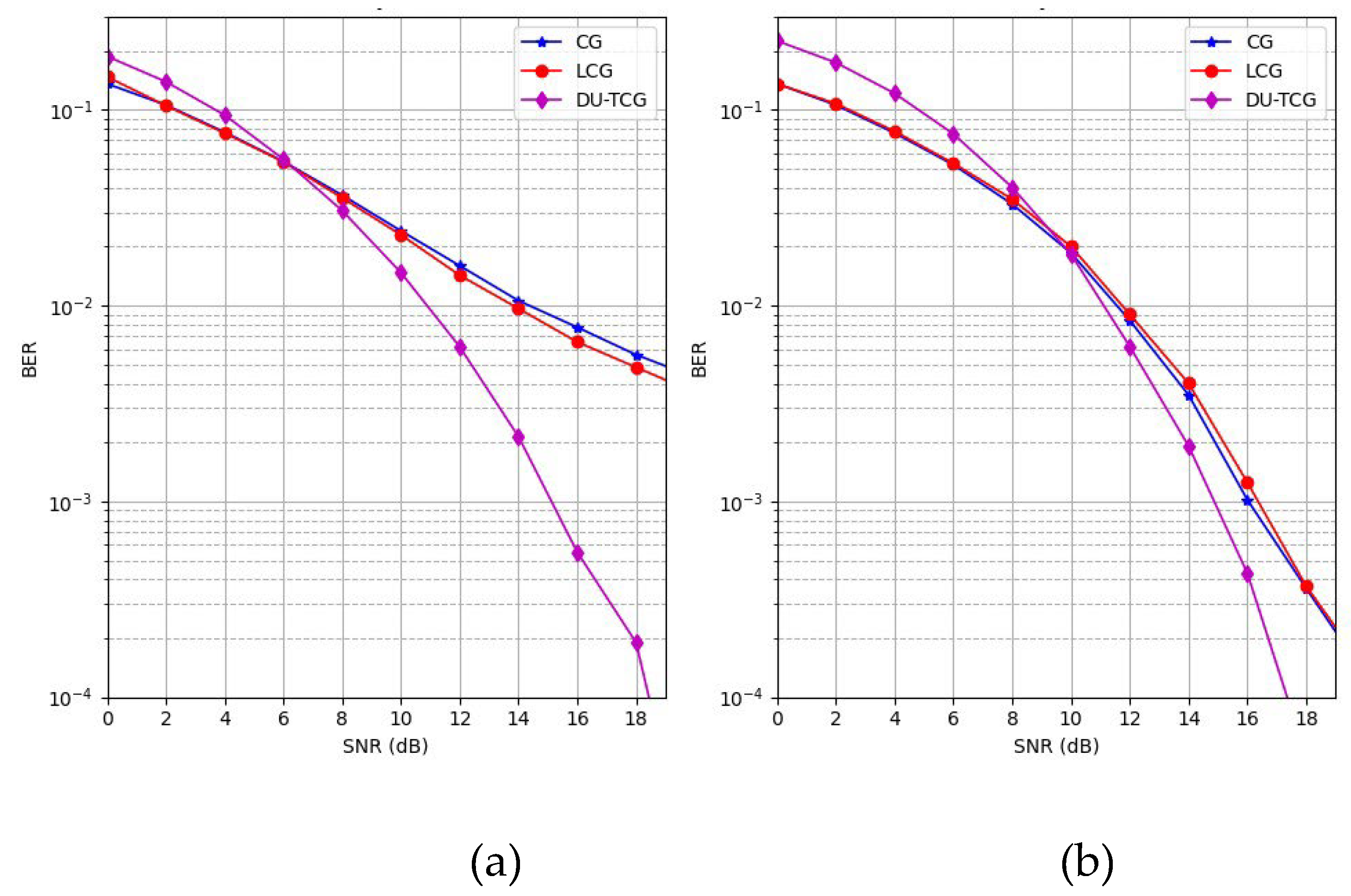
Figure 8 shows that the proposed DU-TCG method outperforms CG and LCG for different number of layers in the 10x10 MIMO layout.
As shown in
Figure 8, DU-TCG exhibit better BER performance with both 5 and 15 layers, compared to the CG and LCG methods. Although the performance of the CG and LCG improves when the number of layers is increased by 3 times, DU-TCG still outperforms these methods. However, as the complexity of the system is directly related by the number of layers, the results shows that DU-TCG is a better candidate in terms of system cost.
Besides the conventional MIMO scheme and channel models discussed above, in
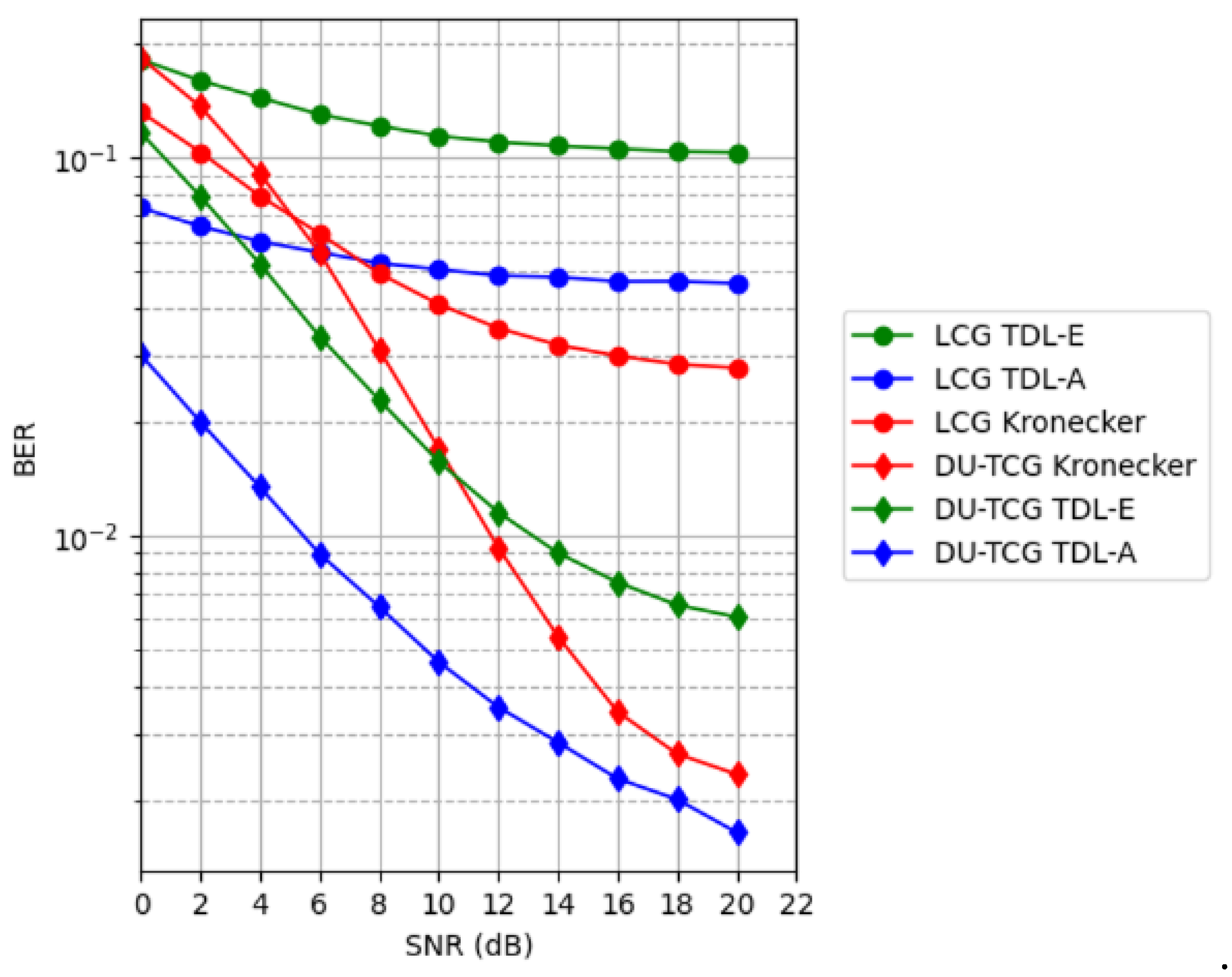
Figure 9 we also compare the performance of DU-TCG with Kronecker, TDL-A and TDL-E channel models for 32x64 MIMO scheme with BPSK modulation. Since the channel conditions are challenging, 15 layers are used here in the training process.
For Kronecker, TDL-A, and TDL-E channel models, both the proposed DU-TCG and existing LCG methods do not have a sufficient detection performance. However, DU-TCG still outperforms the LCG for all three channel models. DU-TCG has employed the benefit of Tikhonov regularization's superiority at the ill-posed problems and DU-TCG's sophisticated regularization mechanism significantly improves the detection process compared to the LCG method.
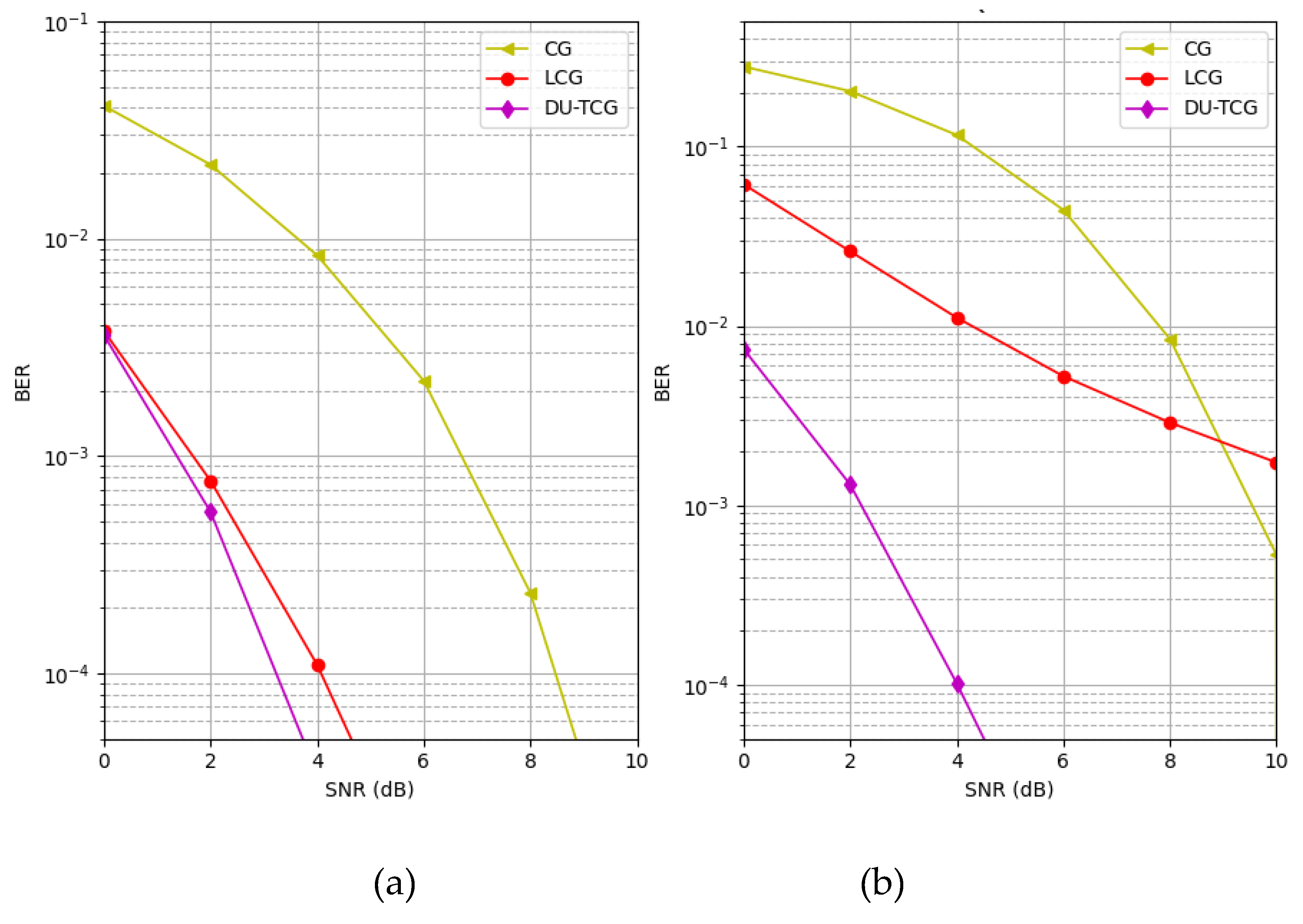
Figure 10 gives the BER performance of CG, LCG, and the proposed DU-TCG methods for BPSK and QAM16 modulation types for a 32x128 MIMO layout in TDL-A channel.
It is well known that the performance of iterative detection methods increases significantly when the number of receiving antennas is much greater than the number of transmitting antennas, and this effect is reflected in our simulation results using the DU-TCG, LCG and CG methods.
Figure 10 shows the results of the system with such a MIMO structure. The detection performance of LCG is close to DU-TCG for lower order modulations in a difficult channel condition such as TDL-A, while DU-TCG outperforms LCG for a higher order modulation. The figure demonstares that the BER of DU-TCG is up to 1.2 times better than LCG when using BPSK modulation under TDL-A fading and up to 8.3 times better when using QAM16 modulation. The superior performance of DU-TCG for difficult conditions such as a high-order modulation system suggests that integrating a regularization term into a deep-unfolded method will help convergence stability and hence improve detection performance.
In
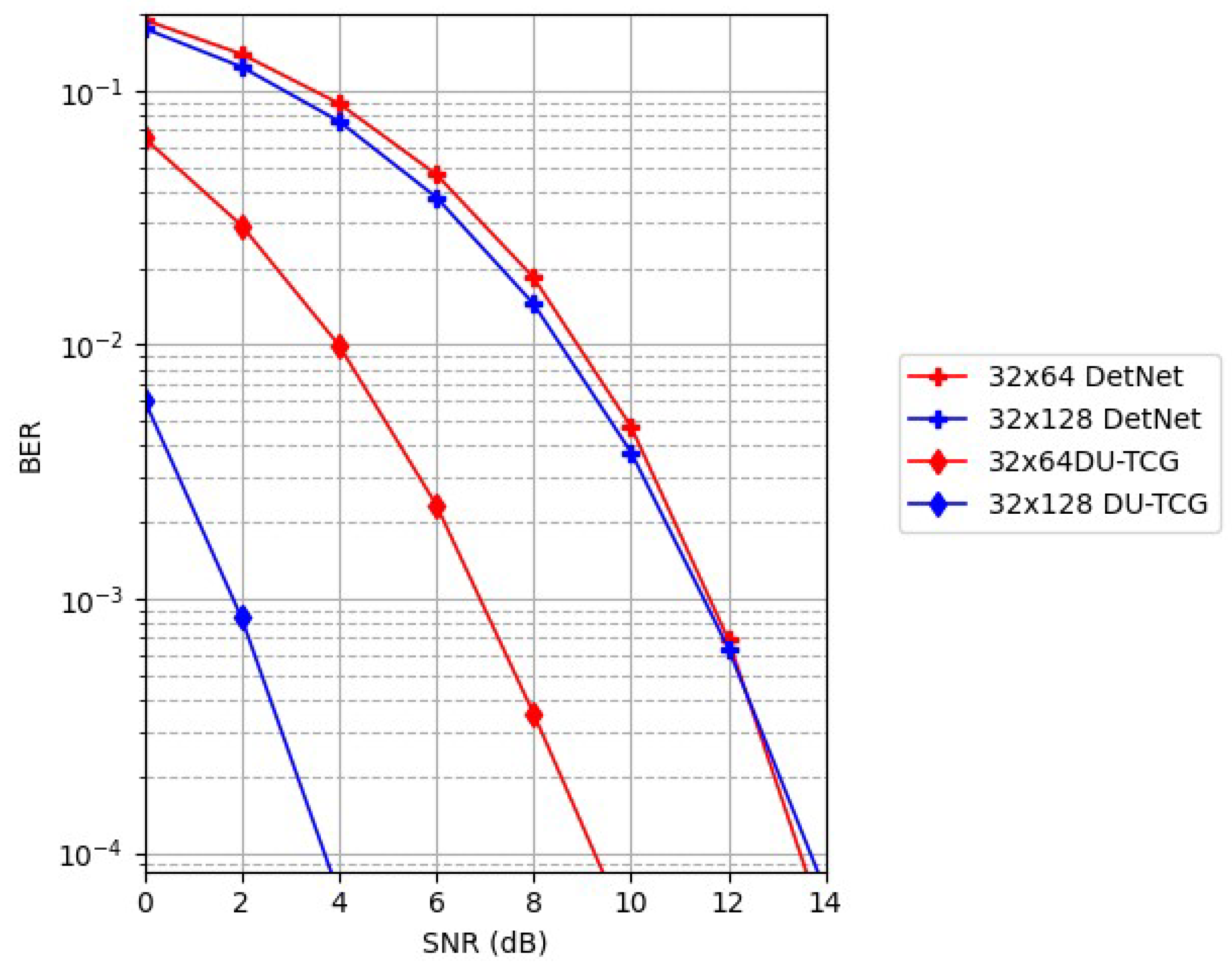
Figure 11, we compare the detection performace of the proposed DU-TCG method with DetNet over a range of MIMO layouts.
Known for its creative use of deep learning models to improve signal detection accuracy, DetNet is considered one of the pioneering efforts in deep unfolding MIMO detection. DetNet has a large number of trainable parameters, which can increase computational complexity and resource requirements. This is one of the main challenges of DetNet. These high computational demands mean that, despite its success, DetNet often struggles with scalability, resulting in longer training times and higher computational costs. DU-TCG, on the other hand, consistently outperforms DetNet in a wide range of MIMO configurations and maintains a lower BER as system complexity increases. For the 32x128 configuration, DU-TCG's BER remains up to 2.9 times lower than DetNet's, demonstrating its strong performance even at higher antenna counts. While the number of trainable parameters in DetNet are eight for each layer, =, it is three for proposed DU-TCG method, =. Thanks to its simplified methodology and elaborated regularization technique, DU-TCG strikes a balance between computational efficiency and performance. DU-TCG's greater ability to manage dynamic and diverse modern communication channels, particularly in high-density and complex signal environments, is demonstrated by the reduced BER it achieves. These results highlight the usefulness of DU-TCG, providing better performance without excessive computational cost and demonstrating its effectiveness as a flexible detection technique for next-generation communications systems.
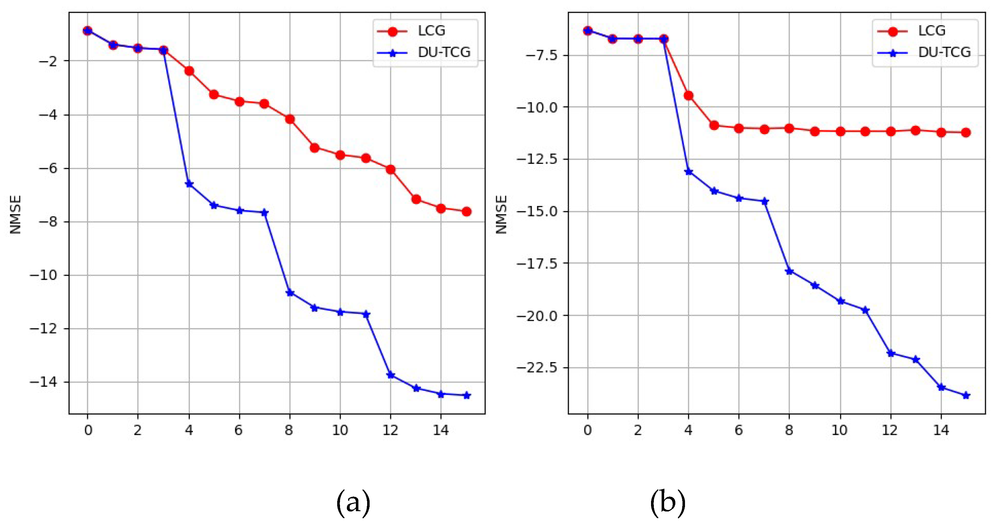
The NMSE performance of the proposed DU-TCG and LCG methods, shown in logarithmic scale, for scalar and vector parameterization, is illustrated in
Figure 12 for a 32x64 MIMO layout.
Figure 12 shows that how scalar and vector parameterization affect the NMSE. As the simulation results show, in the case of scalar parameterization, the NMSE decreases with increasing SNR values for both DU-TCG and LCG methods, which indicates that the signal detection performance of the system increases. On the other hand, in the case of vector parameterization, the increase of SNR values for LCG does not affect the NMSE values after a point, while the NMSE value of the proposed DU-TCG continues to decrease. This shows that the performance of the LCG in complex situations remains constant after a certain level and cannot learn effectively. In addition, the NMSE values for vector parameterization approaches are much smaller than those for scalar parametrization, indicating improved detection performance. Therefore, in case of vector parameterization, the effect of regularization on NMSE performance is higher, resulting in better BER performance.
After discussing the effect of scalar or parameterization techniques on the model-driven approaches above, we will show the impact of the same techniques on BER values in
Figure 13.
In terms of BER values, in scalar parameterization DU-TCG and LCG have similar detection performance. Besides, LCG-V outperforms the DU-TCG-S. However, when we employ the vector parameterization with Tikhonov regularization in DU-TCG, more than 1 dB SNR gain is achieved at the BER value compared to LCG-V.
Discussion
In this study, unlike traditional techniques, a method was proposed that integrates the iterative conjugate gradient method with Tikhonov regularization. The regularization matrix, step size and search direction coefficients are used as trainable parameters in a deep unfolding approach. Extensive simulation results that demonstrate the superiority of the proposed method over existing methods were presented.
The results of this study clearly demonstrates that the proposed method, DU-TCG, is an improved detection strategy for MIMO systems, outperforming both state-of-the-art deep learning techniques such as DetNet and LCG, as well as traditional approaches such as MMSE and CG. Combining conjugate-gradient method with Tikhonov regularization approach in a deep learning design successfully reduces the degrading effects of channel conditions and higher order modulation.
The scalability of DU-TCG is demonstrated by its consistent performance in both large (32x128) and small (10x10) MIMO systems, providing broad applicability to MIMO configurations of varying size and complexity. Besides, outperforming performance of the DU-TCG is also shown under various channel conditions such as Kronecker, TDL-A, and TDL-E channel models, which are widely used in advanced communication systems. This research also reveals that DU-TCG surpasses DetNet in various MIMO topologies when system complexity increases. Simulation results also show that the proposed method provides up to 4 dB SNR gain compared to CG with considerably less iterations. In addition, DU-TCG stays ahead of CG and LCG as the number of layers increases, and surpasses LCG's high-layer performance even with fewer layers. Ultimately, as compared to the vector parameterization of LCG, the NMSE and BER performance of DU-TCG are superior. For both scalar and vector parameterization, DU-TCG decreased the NMSE values.
Consequently, this study highlights the advantages of the proposed DU-TCG method for MIMO detection over different scenarios. As a future work, combining Tikhonov regularization with other iterative detection algorithms for MIMO systems may be considered. Besides, reducing computational complexity of model-driven approaches is also another challenge that needs to be discussed in the area of deep-unfolded algorithms.
Author Contributions
Conceptualization, S.K.; methodology, S.K. and A.K.; software, S.K.; validation, S.K. and A.K.; formal analysis, S.K. and A.K.; investigation, S.K. and A.K.; resources, S.K. and A.K.; data curation, S.K.; writing—original draft preparation, S.K. and A.K.; writing—review and editing, A.K.; visualization, S.K.; supervision, A.K. All authors have read and agreed to the published version of the manuscript.
Funding
This research received no external funding.
Data Availability Statement
Dataset available on request from the authors.
Conflicts of Interest
The authors declare no conflicts of interest.
References
- Yang, S.; Hanzo, L. Fifty years of MIMO detection: The road to large-scale MIMOs. IEEE communications surveys & tutorials 2015, 17, 1941–1988. [Google Scholar]
- Albreem, M.A.; Juntti, M.; Shahabuddin, S. Massive MIMO detection techniques: A survey. IEEE Communications Surveys & Tutorials 2019, 21, 3109–3132. [Google Scholar]
- Wu, M.; Yin, B.; Vosoughi, A.; Studer, C.; Cavallaro, J.R.; Dick, C. Approximate matrix inversion for high-throughput data detection in the large-scale MIMO uplink. 2013 IEEE international symposium on circuits and systems (ISCAS), 2013; pp. 2155–2158. [Google Scholar]
- Yin, B.; Wu, M.; Cavallaro, J.R.; Studer, C. Conjugate gradient-based soft-output detection and precoding in massive MIMO systems. IEEE Global Commun. Conf., 2014; pp. 3696–3701. [Google Scholar]
- Hu, Y.; Wang, Z.; Gaol, X.; Ning, J. Low-complexity signal detection using CG method for uplink large-scale MIMO systems. IEEE Int. Conf. Comput. Sci 2014, 477–481. [Google Scholar]
- Dai, L.; Gao, X.; Su, X.; Han, S.; Wang, Z. Low-complexity softoutput signal detection based on Gauss-Seidel method for uplinkmultiuser large-scale MIMO systems. IEEE Trans. Veh. Technol. 2015, 64, 4839–4845. [Google Scholar] [CrossRef]
- Adeva, E.P.; Augustin, T.R.; Fettweis, G.P. Optimizing a pipelined MIMO sphere detector for energy efficiency. IEEE International Conference on Wireless Communications & Signal Processing (WCSP), October 2015; pp. 1–6. [Google Scholar]
- Fukuda, W.; Abiko, T.; Nishimura, T.; Ohgane, T.; Ogawa, Y.; Ohwatari, Y.; Kishiyama, Y. Low-Complexity Detection Based on Belief Propagation in a Massive MIMO System. IEEE 77th Vehicular Technology Conference (VTC Spring), Dresden; 2013; pp. 1–5. [Google Scholar]
- Markus, M.; Ketonen, J. MIMO detector algorithms and their implementations for LTE/LTE-A. November 2010,GIGA seminar.
- Hu, Q.; Gao, F.; Zhang, H.; Li, G.Y.; Xu, Z. Understanding deep MIMO detection. IEEE Transactions on Wireless Communications 2023, 22, 9626–9639. [Google Scholar] [CrossRef]
- He, H.; Wen, C.K.; Jin, S.; Li, G.Y. A model-driven deep learning network for MIMO detection. IEEE Global Conference on Signal and Information Processing (GlobalSIP), November 2018; pp. 584–588. [Google Scholar]
- Un, M.W.; Shao, M.; Ma, W.K.; Ching, P.C. Deep MIMO detection using ADMM unfolding. IEEE Data Science Workshop (DSW), June 2019; pp. 333–337. [Google Scholar]
- Shlezinger, N.; Eldar, Y.C.; Farsad, N.; Goldsmith, A.J. Viterbinet: Symbol detection using a deep learning based viterbi algorithm. IEEE 20th International Workshop on Signal Processing Advances in Wireless Communications (SPAWC), July 2019; pp. 1–5. [Google Scholar]
- Ge, Y.; Tan, X.; Ji, Z.; Zhang, Z.; You, X.; Zhang, C. Improving approximate expectation propagation massive MIMO detector with deep learning. IEEE Wireless Communications Letters 2021, 10, 2145–2149. [Google Scholar] [CrossRef]
- O’Shea, T.J.; Erpek, T.; Clancy, T.C. Deep learning-based MIMO communications. arXiv preprint 2017, arXiv:1707.07980. [Google Scholar]
- Baek, M.-S.; Kwak, S.; Jung, J.-Y.; Kim, H.M.; Choi, D.-J. Implementation methodologies of deep learning-based signal detection for conventional MIMO transmitters. IEEE Transactions on Broadcasting 2019, 65, 636–642. [Google Scholar] [CrossRef]
- Samuel, N.; Diskin, T.; Wiesel, A. Deep MIMO detection. IEEE 18th International Workshop on Signal Processing Advances in Wireless Communications (SPAWC), July 2017; pp. 1–5. [Google Scholar]
- Chen, Q.; Zhang, S.; Xu, S.; Cao, S. Efficient MIMO detection with imperfect channel knowledge-a deep learning approach. IEEE wireless communications and networking conference (WCNC), April 2019; pp. 1–6. [Google Scholar]
- Faghani, T.; Shojaeifard, A.; Wong, K.K.; Aghvami, A.H. Deep learning-based decision region for MIMO detection. IEEE 30th Annual International Symposium on Personal, Indoor and Mobile Radio Communications (PIMRC), September 2019; pp. 1–5. [Google Scholar]
- Hershey, J.R.; Roux, J. L.; Weninger, F. Deep unfolding: Model-based inspiration of novel deep architectures. arXiv preprint 2014, arXiv:1409.2574. [Google Scholar]
- Balatsoukas-Stimming, A.; Studer, C. Deep unfolding for communications systems: A survey and some new directions. IEEE International Workshop on Signal Processing Systems (SiPS), October 2019; pp. 266–271. [Google Scholar]
- Yu, Y.; Ying, J.; Zhang, S.; Wang, J.; Guo, L.; Shang, J.; Wang, P. A deep learning approach based on Richardson and Gauss–Seidel for massive MIMO detection. Transactions on Emerging Telecommunications Technologies 2024, 35, e4947. [Google Scholar] [CrossRef]
- Sirois, S.; Ahmed Ouameur, M.; Massicotte. Deep Unfolded Extended Conjugate Gradient Method for Massive MIMO Processing with Application to Reciprocity Calibration. J Sign Process Syst. 2021. [Google Scholar] [CrossRef]
- Qin, Z.; Ye, H.; Li, G.Y.; Juang, B.H.F. Deep learning in physical layer communications. IEEE Wireless Communications 2019, 26, 93–99. [Google Scholar] [CrossRef]
- Zappone, A.; Di Renzo, M.; Debbah, M. Wireless networks design in the era of deep learning: Model-based, AI-based, or both? IEEE Transactions on Communications 2019, 67, 7331–7376. [Google Scholar] [CrossRef]
- Björnson, E.; Giselsson, P. Two applications of deep learning in the physical layer of communication systems. arXiv preprint 2020, arXiv:2001.03350. [Google Scholar]
- Takabe, S.; Imanishi, M.; Wadayama, T.; Hayakawa, R.; Hayashi, K. Trainable projected gradient detector for massive overloaded MIMO channels: Data-driven tuning approach. IEEE Access 2019, 7, 93326–93338. [Google Scholar] [CrossRef]
- Wei, Y.; Zhao, M.M.; Hong, M.; Zhao, M.J.; Lei, M. Learned conjugate gradient descent network for massive MIMO detection. IEEE Transactions on Signal Processing 2020, 68, 6336–6349. [Google Scholar] [CrossRef]
- Ahmed Ouameur, M.; Massicotte, D. Early results on deep unfolded conjugate gradient-based large-scale MIMO detection. IET Communications 2021, 15, 435–444. [Google Scholar] [CrossRef]
- Liu, X.; Li, Y. Deep MIMO detection based on belief propagation. IEEE Information Theory Workshop (ITW), November 2018; pp. 1–5. [Google Scholar]
- Loyka, S.L. Channel capacity of MIMO architecture using the exponential correlation matrix. IEEE Communications letters 2001, 5, 369–371. [Google Scholar] [CrossRef]
- 3GPP TR 38.901: Technical specification group radio access network; Study on channel model for frequencies from 0.5 to 100 GHz. 2018. In https://www.3gpp.org/ftp/Specs/archive/38 series/.
- van Etten, W. Maximum likelihood receiver for multiple channel transmission systems. IEEE Transactions on Communications 1976, 24, 276–283. [Google Scholar] [CrossRef]
- Yu, Y.; Ying, J.; Wang, P.; Guo, L. A data-driven deep learning network for massive MIMO detection with high-order QAM. Journal of Communications and Networks 2023, 25, 50–60. [Google Scholar] [CrossRef]
- Hestenes, M.R.; Stiefel, E. Methods of Conjugate Gradients for Solving Linear Systems. Journal of Research of the National Bureau of Standards 1952, 49, 409–435. [Google Scholar] [CrossRef]
- Albreem, M.A.; Alhabbash, A.H.; Shahabuddin, S.; Juntti, M. Deep learning for massive MIMO uplink detectors. IEEE Communications Surveys & Tutorials 2021, 24, 741–766. [Google Scholar]
- Buccini, A.; Donatelli, M.; Reichel, L. Iterated Tikhonov regularization with a general penalty term. Numerical Linear Algebra with Applications 2017, 24, e2089. [Google Scholar] [CrossRef]
- Bianchi, D.; Buccini, A.; Donatelli, M.; Serra-Capizzano, S. Iterated fractional Tikhonov regularization. Inverse Problems 2015, 31, 055005. [Google Scholar] [CrossRef]
- Kingma, D.P.; Ba, J. Adam: A method for stochastic optimization. arXiv preprint 2014, arXiv:1412.6980.37. [Google Scholar]
|
Disclaimer/Publisher’s Note: The statements, opinions and data contained in all publications are solely those of the individual author(s) and contributor(s) and not of MDPI and/or the editor(s). MDPI and/or the editor(s) disclaim responsibility for any injury to people or property resulting from any ideas, methods, instructions or products referred to in the content. |
© 2024 by the authors. Licensee MDPI, Basel, Switzerland. This article is an open access article distributed under the terms and conditions of the Creative Commons Attribution (CC BY) license (http://creativecommons.org/licenses/by/4.0/).
