1. Introduction
Form factors are a paramount physical manifold which facilitates to intervene in all the processes that involve radiative heat transfer. As this ever-present form of heat transfer takes place without any kind of contact between the intervening bodies, the forms and spatial relationships of the said elements are pivotal to define to which extent energy is emitted and received [
1]. In other words, the distribution and appearance of radiation fields is a functional of the volumetric or three-dimensional disposition of the bodies that exchange radiation [
2]. It is easy to outline the process for differential elements but if the need arouses to the extend the issue to well defined geometries, like the circle, the spheroid or the triangle [
3,
4] a great number of drawbacks and shortcomings appears often provoking that we fell short of reliable or robust solutions to the problem. From the mathematical point of view, it is necessary to introduce two rounds of double integrals, very different in nature, that become more complex with every primitive found [
4]. Conventional calculus is, so to speak, put at a stake here, but approximate solutions fall of the mark and do not provide a satisfactory output [
5]. Therefore, we need to overcome this problem to avoid increasing errors that menace the stability of the whole process.
Innovative tendencies in the matter, like for instance, finite elements or discretization are insufficient because generally speaking there is no adequate discretization of curved bodies like circles or spheres, even in some cases, we can find problems with triangular tiles. Stochastic methods are often as cumbersome as inaccurate. [
6,
7].
For this manuscript the author proposes a novel methodology based on employing some specific constants subsequently turned into variables, to perform the early parts of the fourfold integral, and completely exact. Previously only the rectangle and the complete circle had been resolved by total integration and the author has collaborated to clarify this especially for the case of cuboids. [
8]. It remains surprising the comparatively simple shapes like the semicircle or the derived sector could not be added to the list of exact solutions although mathematical constraints made it difficult to surmount the [
9].
In the fashion that we have proposed above, the last phase of integration is prepared to be completed by numerical methods which we will explain in more detail in the corresponding chapter. [
10]. We need to consider that in the first stage only the more feasible configuration factor (a double integral) is considered instead of addressing the form factor (fourfold integral) directly. [
8]. A significant part of the hindrances found resides in the complexity of spatial bodies that often appear in natural or man-made objects in which the occurrence of radiation is important [
11,
12].
Until now, diverse approaches to these matters have been attempted without success. The circle and circular sectors and segments are generally speaking indivisible in simpler shapes. [
13]. The exact solving of the forms that appear in the problem might be deemed an important finding and an advance by its own merits; it accrues to a number of postulates on thermal radiation proposed thus far [
14]. The most straightforward application is radiation on the arched entrances of tunnels. Finally, the formulations in algebraic terms are incorporated to the software which we have developed. In the following chapters we expect to develop in more detail how the whole process has been completed.
2. Materials and Methods. General Expression of Reciprocity in Radiative Exchanges
As it has been enunciated several times since the last quarter of the 18
th century [
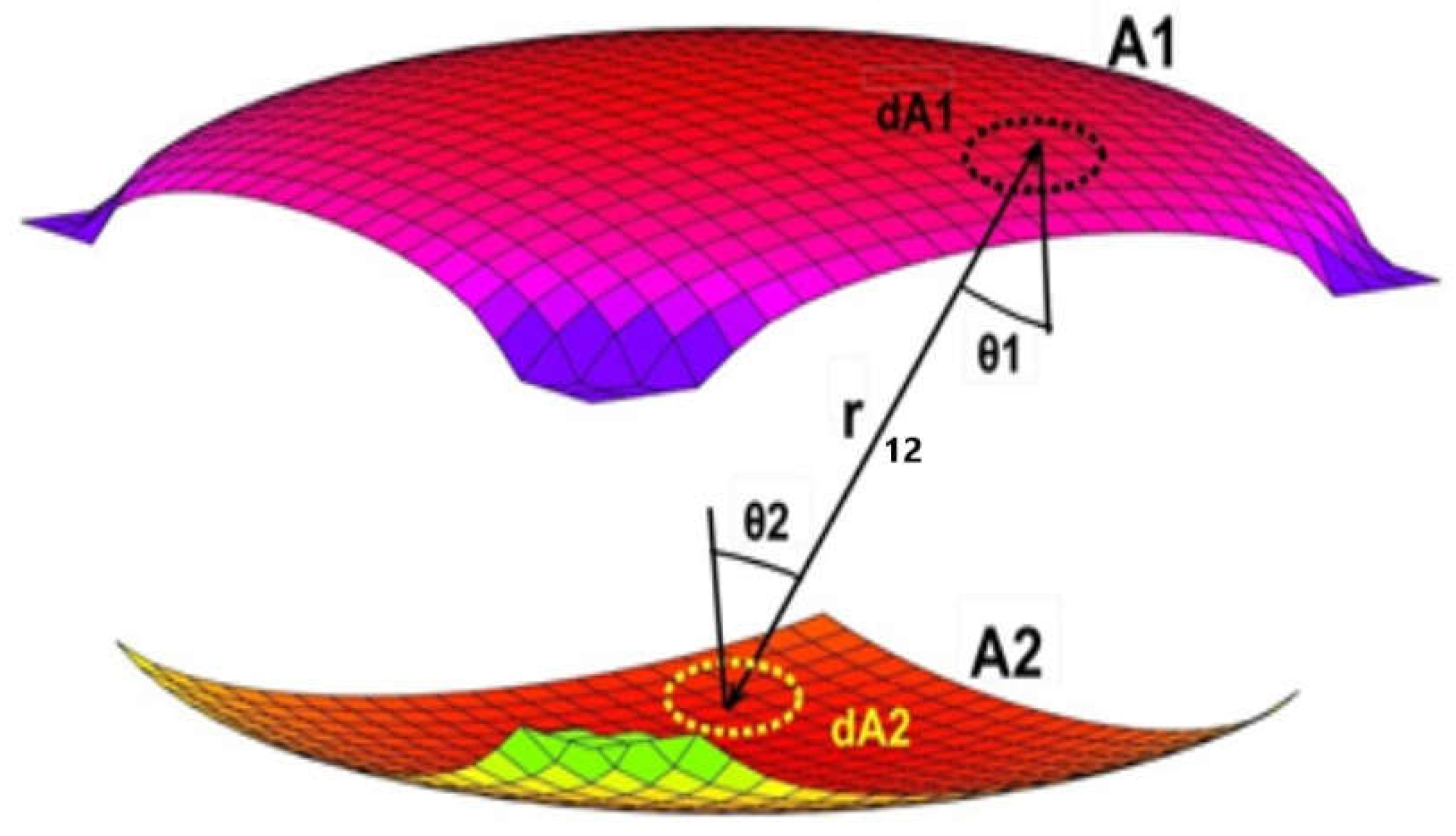
15] We will begin with the canonical expression that regulates the emission and reception of radiative energy between two non-black bodies of any spatial configuration and regardless of their respective positions as shown in
Figure 1, the equation is composed mainly of directional cosines, distances and areas under the following form (Eq.1):
Equation 1 is often termed the reciprocity principle, the first to propose it was Johann H. Lambert [
16,
17,
18] around 1760. It describes the respective quantity of radiative energy by unit area that will strike any of the two surfaces involved, that is, E
1 and E
2. The corresponding incident angles θ
1 and θ
2 which are shown in the figure stand for the inclination to the normal of the distance line that joins two arbitrary points pertaining to each surface called r
12, both in the equation and in the figure [
19].
In order to solve Eq. 1, which implies finding the amount of a form factor that encompasses the two sources, we need to work out four ascending steps of integration, as explicated in Eq. (2) [
20].
Nonetheless, in this manuscript we would focus on the first and second steps (Eq. 3), which are more accessible, leaving a sort of envoy for the next step which adopts the form of a constant (x
0) which turns into a variable in the subsequent phases [
21], that is, it becomes active for the last two stages of integration.
We propose that the last two operations can be executed using a numerical method that extends the former findings to the surface of emission as a sort of mean or average. In this way we attain the desired figure of the form factor attributed to the two surface sources considered with considerable accuracy. [
22]. Afterwards, we would show how to apply the so-found form factors for several three-dimensional configurations that come up in parts of radiation emitting or receiving devices and in openings of buildings. [
23,
24].
For other different positions of the surface sources, an exact solution has not been achieved yet [
5]. Neither for irregular fragments of circular sectors, rectangles and circles or even for the familiar form of the sphere [
25,
26].
Partially conceived methods to address the preliminary integrals have been presented occasionally [
27]. They tend to show the exchanges between the circle and a single point of the receiving surface, sometimes they adopt the form of blurry tables, with confusing entries [
28,
29]. Instead we will elaborate the complete formulation in standard mathematical language.
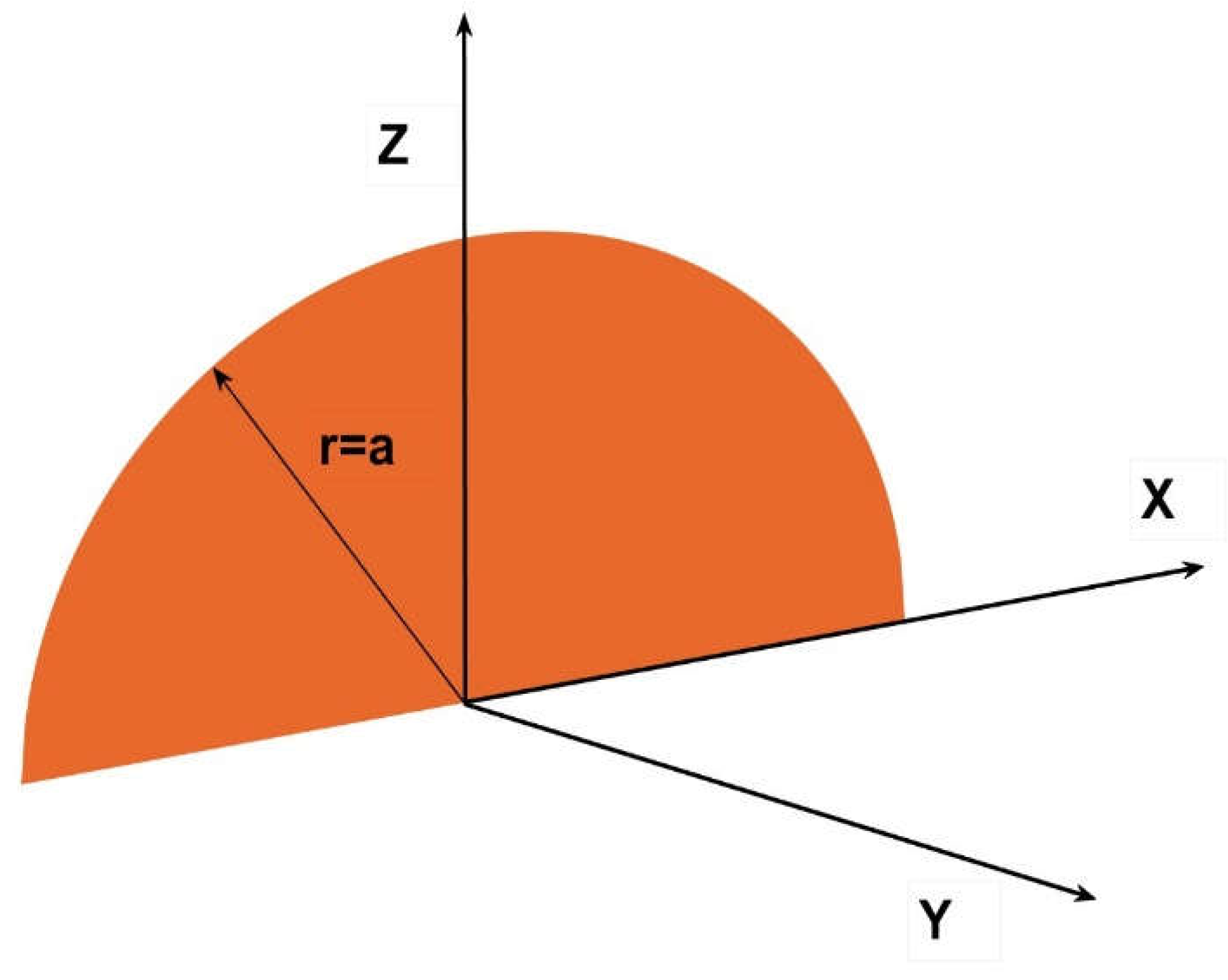
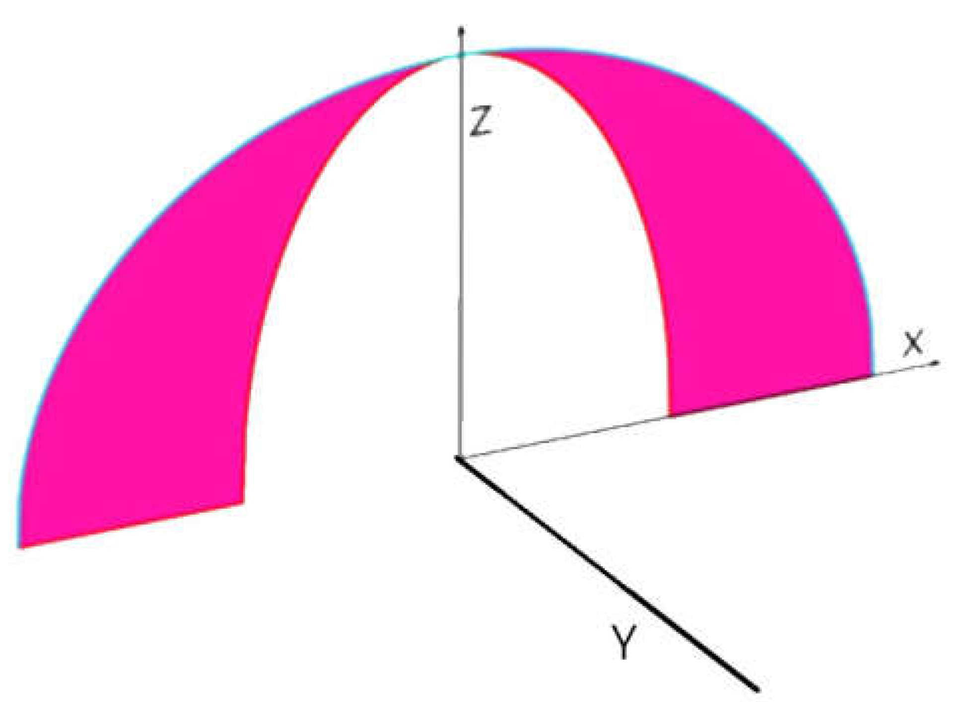
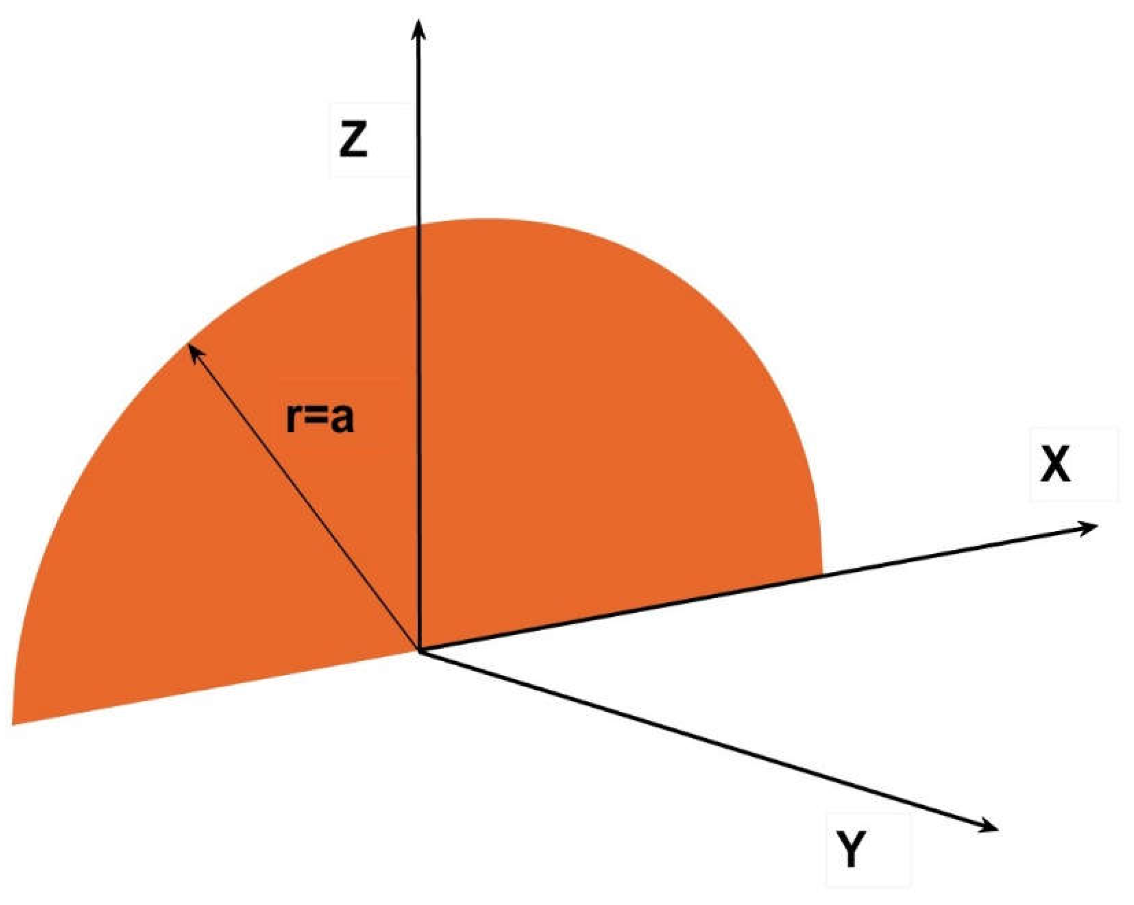
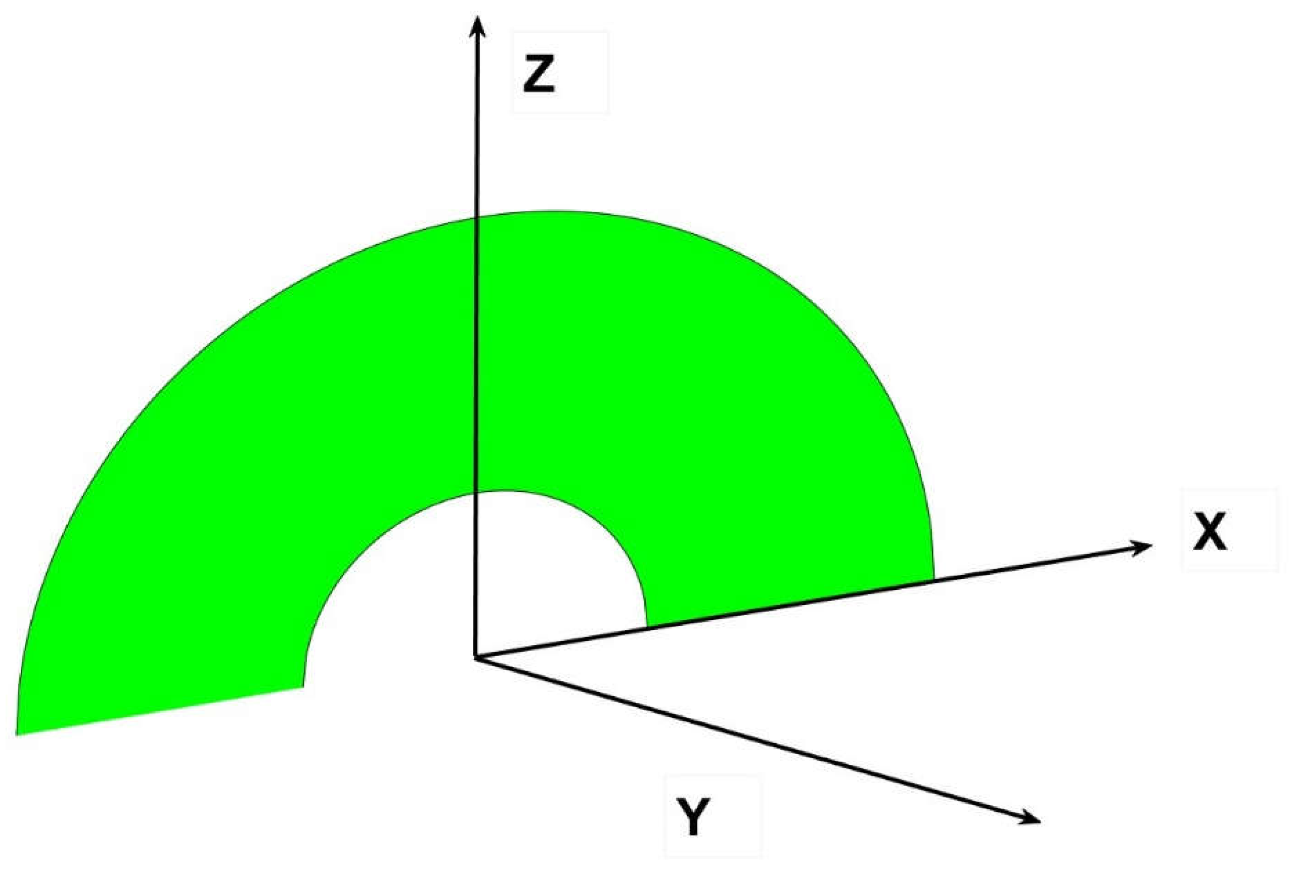
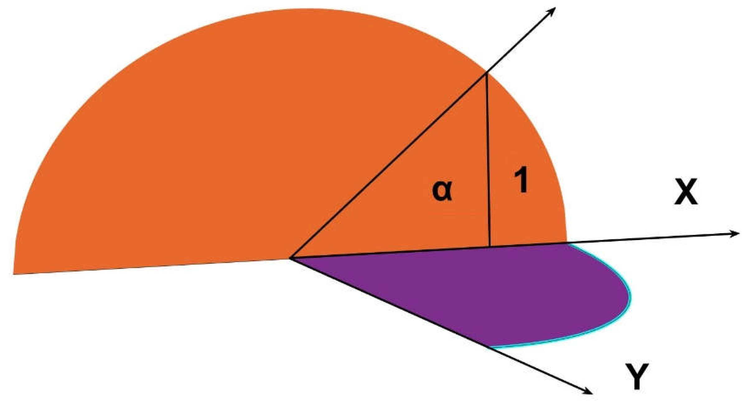
In order to develop our method, we start for simplicity with a semicircle of radius a, placed at the intersection of the main axes X, Y and Z (
Figure 2).
Under this disposition, the coordinate Z axis is vertical and X is horizontal and perpendicular, Y axis is perpendicular to the semicircle, the radius of the circular sector turns, in Z, equal to rsinα, and in X, to rcosα as in
Figure 2
Although it will be demonstrated in the appendix that the integration could be easily performed in cartesian coordinates by bringing in the expression of the semicircle, we would work in this case in polar coordinates to better explain the relevance of changing the angle α [
30].
The axis Y in the graph represents the free coordinate perpendicular to X.
Introducing the variable x , limited at first to the semicircle but extended freely in the second part of the proccess, the distance vector (Eq.4) from one receiving point pertaining to the semicircle to another emitting point moving freely over the plane XY, presented as r
12 in Eq. 2 above, would be in caertesian coordinates:
The respective cosines β and γ, to the normal from Eqs. 1 to 3, would be accordingly y/r12 and z/r12, z in this case is equal to rsinα, as mentioned.
The integral to solve derived from Eq.3, would then result in (Eq. 5):
We need to solve the root equation for a generality of types of circular sectors and segments in diverse positions [
31]. To avoid controversial points, we will give the expression for the second step of configuration factor, that is we will solve the double integral in the first place, which give the form factor on a point grid on the surface of a rectangular emitter. When this is achieved, we would use a different property demonstrated by the author [
32], by virtue of which the full form factor equates to the mean of the point grid over the emitting surface. Utilizing the tools of numerical methods such planar grid can have any form, rectangular, elliptic or circular, since the average is limited to the points inside the boundary of the shape selected. In a not dissimilar procedure, we can find the total form factors for volumes composed of circular sements, for instance the space determined by an octave of sphere. Internal reflections inside the volumes created (three sides are quarter of circles forming a trihedron and the covering surface is an eight of a sphere) can be determined by special sets of four equations taking into account that one of the surface sources is not planar, see appendix 2 [
33].
By combining the circular sectors, with triangles, rectangles or ellipses we can attaing a wider range of forms that were previously unimaginable and not suitable for calculation, which is why the novel procedure that we propose will provide a significant contribution [
34].
3. Results. Solutions for various forms of circular sectors
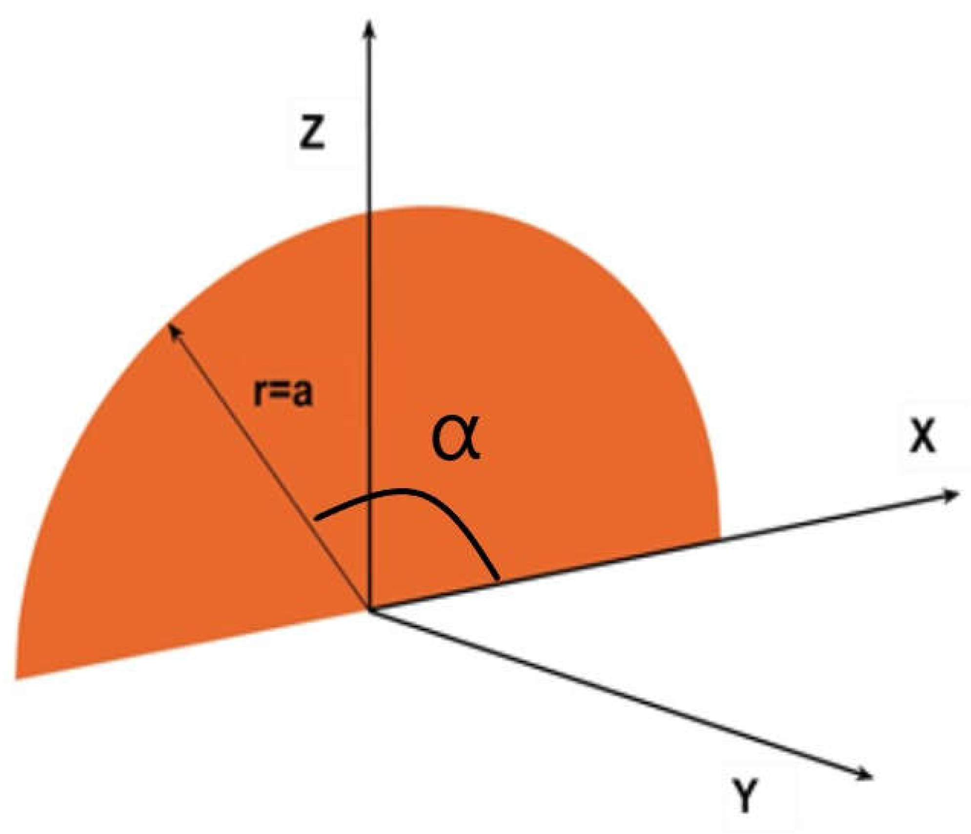
We will summarize and outline below the more important aspects of the integration process. (
Figure 3)
In this case the canonical integral in polar coordinates, as mentioned in Eq. 5 turns out to be (Eq.6):
As stated, first we would extend the integral to π which would represent the whole semicircle. If we integrate with respect to α , in the numerator we would find the derivative of cosα, -sinα. Therefore by making cosα=t, dt=-sinαdα this integral reduces to,
The primitive is, accordingly, just the quotient of the numerator
Then, the last integral to solve is,
Whose primitives are a combination of a logarithm and an arc of tangent, for the first term,
And substituting, we find,
Multiplying by
and grouping, the final result is expressed as,
Or in a more developed form,
The same result has been obtained by the author in Cartesian coordinates, see
Appendix A.
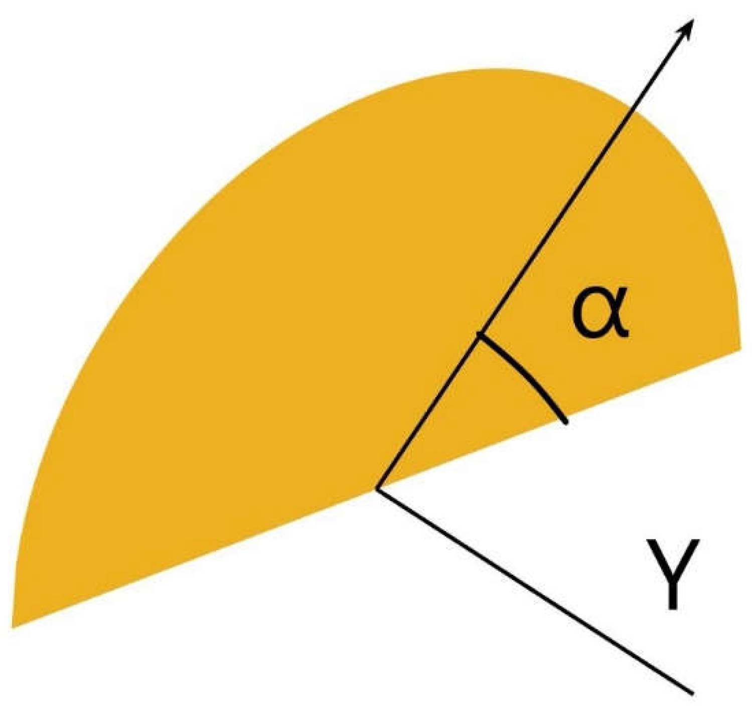
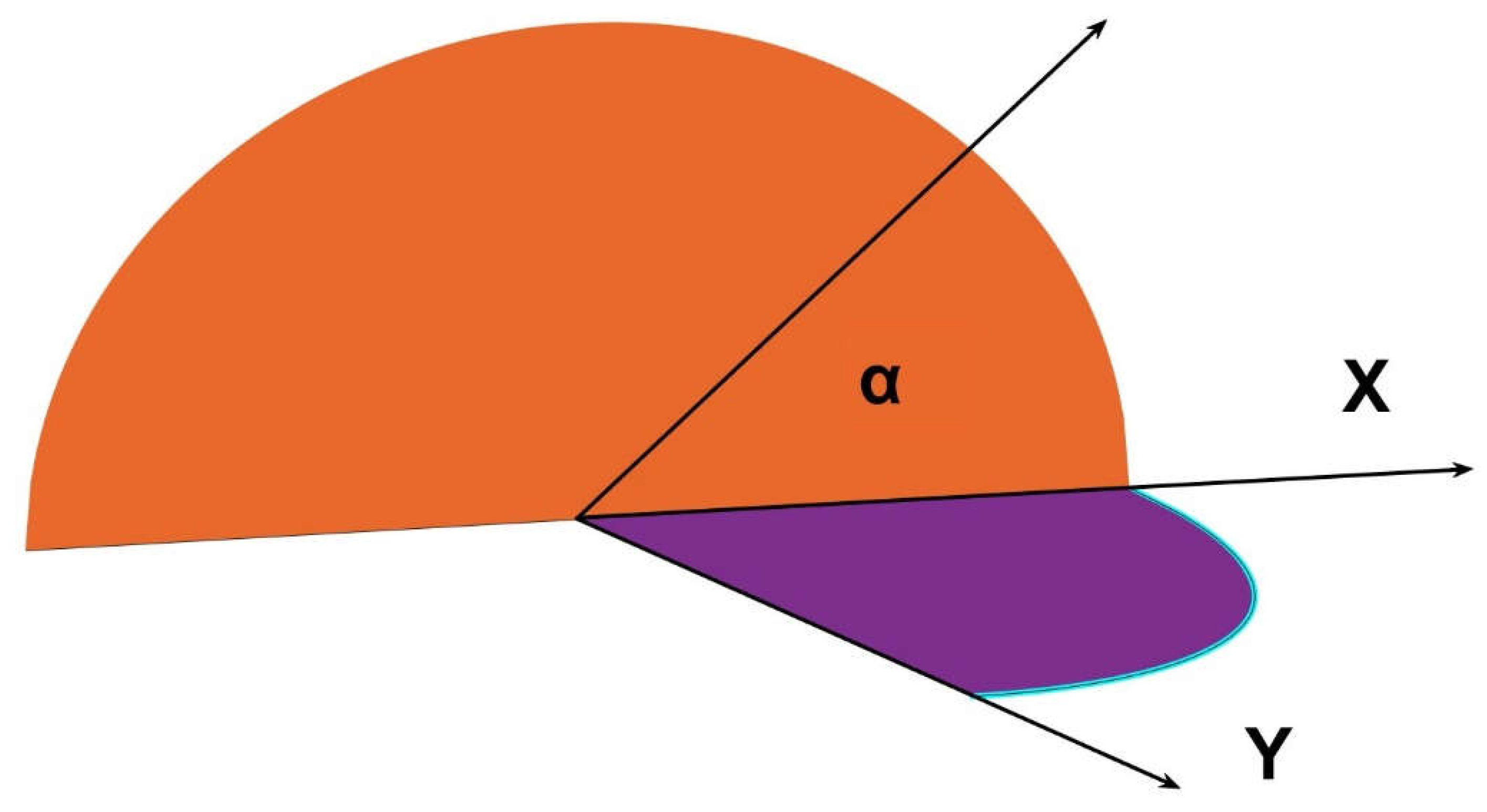
From this result onwards, by using different values of the angle α, (see
Figure 4), we can obtain a number of form factors as follows.
In time, we have been able to solve the same integral not only for the whole angle π, but in terms of α, that gives
Following, we gather a small but representative collection of new form factors depending on the angle subtended by the circular sector [
35].
1.- For the semicircle (angle α = π), as already obtained,
A further simplification is,
An if we call S = r+x and T=r-x, Eq. 17 is reduced to,
2.- For another typical value, the quarter of circle (angle α = π /2),
3.- For the sixth of circle (angle α = π /3),
4.- For the octave of circle (angle α = π /4),
5.- For the twelfth of circle (angle α = π /6),
Thus, for any angular fraction α within the semicircle whose cosine, C goes from 1 (0) to -1 (π), we receive a new Cabeza-Lainez’ postulate number 18 [
36]:
Which in formal notation is,
By subtraction of two different α angles, α
1 α
2 (being α
2 the larger, we would find the form factor for any circular segment at any position within the frame of the semicircle. Substituing (Eq. 25):
As the sum of arctan(A) and arctan(B) can be grouped in a single arc of tangent, if AB<1.
But C
1=cos(α
1) and (1- C
12)=sin
2(α
2), therefore we can write, Eq. 26.
Where α2 represents the bigger angle (and the lower cosine), while r is the radius of the circular sector.
If we make,
and
;
4. Possible Combinations of the Former Results
We have already obtained important and even revolutionary result for some fields of research like for instance the lighting and glare avoidance of tunnels and underground facilities [
37]in which the radiation due to the circular opening (or otherwise like elliptic or parabolic was completely unknown). However, by combining these results with other, previously obtained by the author[
38] we can extend the findings much further or apparently whithout limits.
In the first place we will incorporate the triangle with the circular sector.
The result for the form factor of the triangle with the point moving freely over x and y is,[
12]
If, for instance, we make a triangle with angle π/4 and we would like the hypotenuse to be r as it happens for instance in the octave of a circle, the short sides of the triangle a=b would logically be equal to r*(√2/2). Substituting a, and b in the above formula it is easy to obtain the following:
However, this is similar to the first term of the result for an octave of circle (Eq. 19) and we have to assume accordingly that the second positive term, plus the new term found gives, when subtracted,
Or for a general angle α,
We need to remember that in this particular case, cosα=√2/2 .
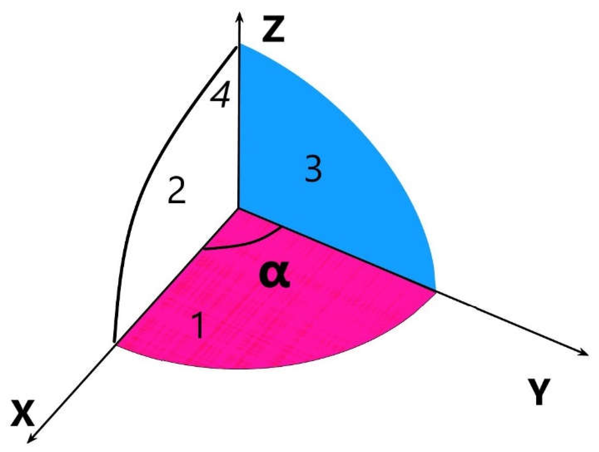
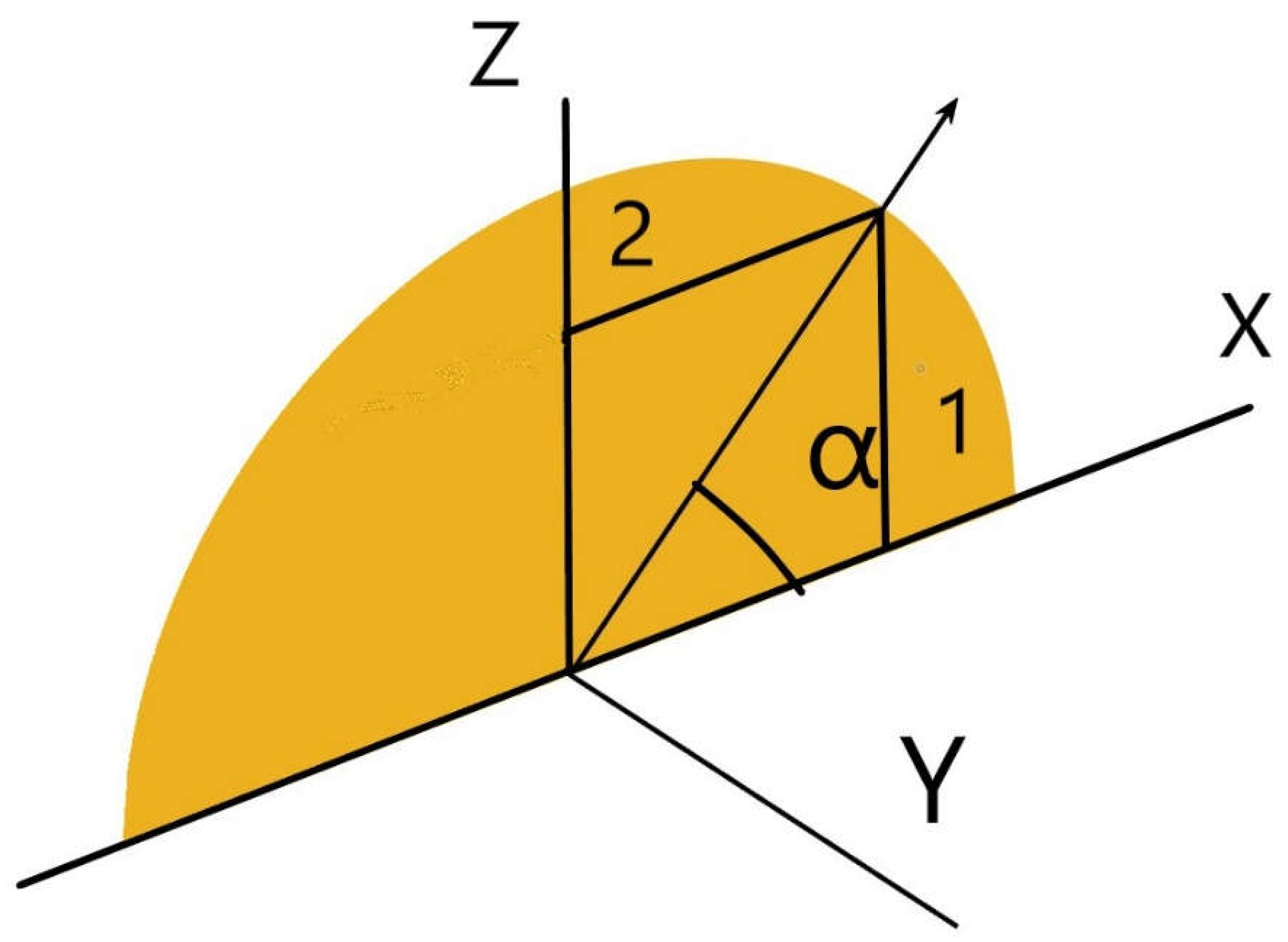
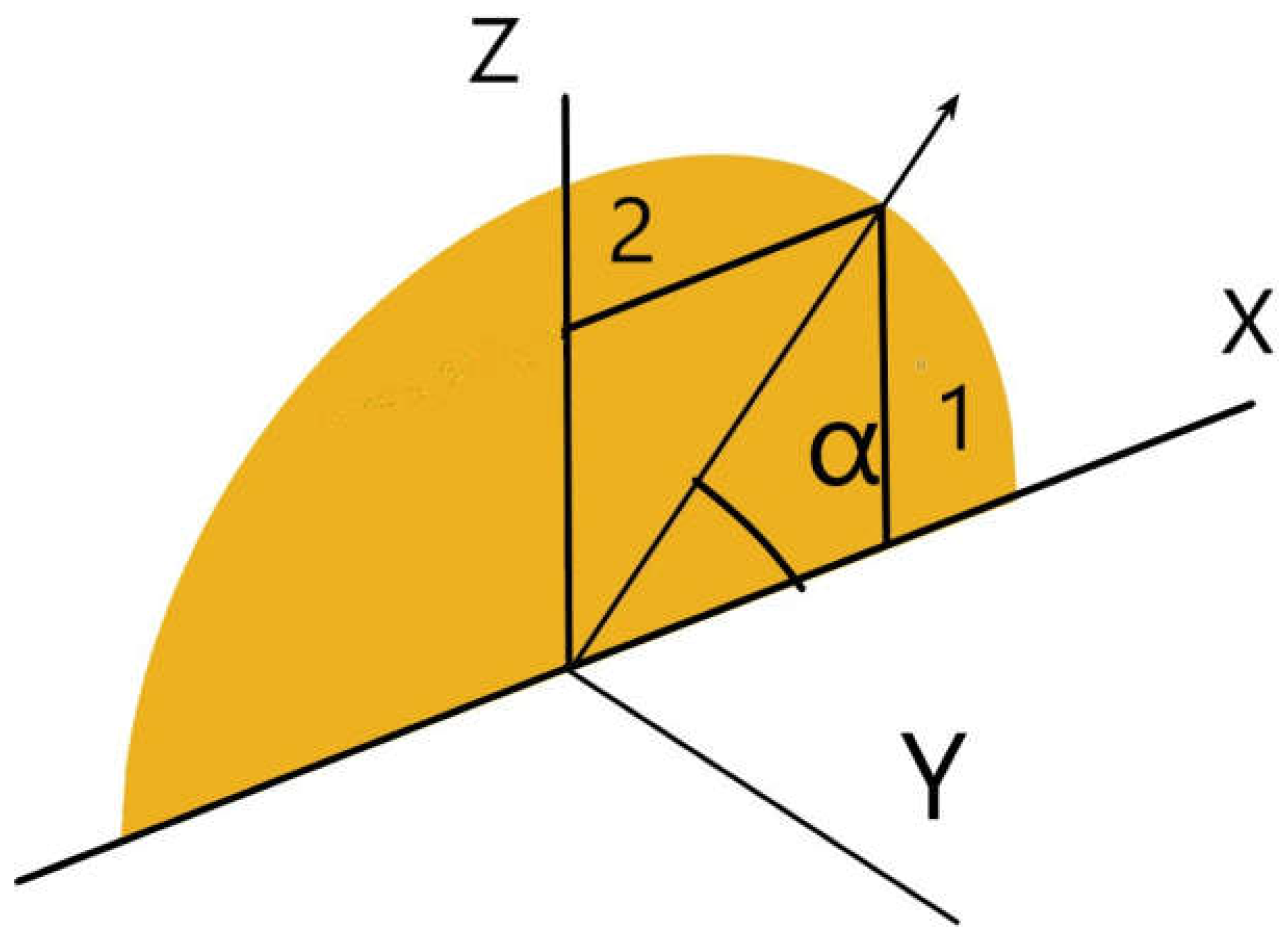
Eqs. 28 and 29, represent the factor introduced by the half circular segment (region 1, in Fig.X) that added to the triangle completes the octave. By virtue of which, we have found a new and unbeknownst configuration factor.
If we should add now the form factor of rectangles or squares, as the case may be, we could find the corresponding expression for the upper segment of the circle (region 2, in
Figure 5) which, to our knowledge, has not yet been defined in the literature.
Let us continue the example by introducing a radiating rectangle (square, a=b), over a free dimension horizontal plane, the defining equation is, as we known,
The factor for the quarter of the circle was, (Eq. 21)
By subtracting both factors, we receive,
The factor for the horizontal and vertical segments of circle outside of the square is ,
In this particular case r equals a√2 ,
If we want to obtain the value of the upper segment alone we need to subtract the factor previously found before,
With which, we have added a considerable amount of new form factors. Substituting a by rcosα,
Eq. 40 coincides with the generic factor, if we remember that a= rsinα = rcosα as the angle is π/4, and also because of that, r=a√2
In a more general case, we have that for any triangle, the form factor is
But in relation to the radius r of a circular segment, we known that a=rsinα and b=rcosα, and substituting,
And simplifying, it leaves,
For a generic rectangle with the same substitution of a and b, we would have
Applying the said substitution,
The form factor for the generic circular sector was,
Then the vertical segment would turn into,
And simplifying a bit more,
Accordingly we can find the upper generic circular segment, to the general expression for the quarter of circle,
We need to subtract the form factor of the rectangle,
But first, we proceed to substitute with the values of a and b as a function of the radius.
Then we perform the first operation to give,
And finally we need to subtract the value found for the vertical segment of the circle,
The new generic form factor thus obtained is,
Achieving the final results hereby exposed,
Lower vertical circular segment,
Upper horizontal circular segment,
With adequate adroitness we can find by addition and subtraction an unlimited number of new form factors [
39], but the emitting surface must be the same for all the bodies involved, usually the larger one [
40]. Consider for instance the annulus in the
Figure 7.
We can find the form factor of a circular ring by subtracting the smaller semicircle from the larger one. The two radiuses are r and r
1, with r > r
1 . The horizontal surface on which we proceed with the calculations has to be the same for both semicircles, that is a rectangle or surface larger than the outer half-disk [
41].
5. Advance to Three-Dimensional Results and Calculation of the Total Form Factor
As we have stated in the introduction, to proceed with the toal form factor between two finite surfaces, we need to obtain a sort of mean of the previous formulas over the whole emitting surface (a rectangle in the most simple case). It suffices to compute the values of the configuration factor at each point of the rectangle and calculate the average by numerical methods [
42]. This has been mathematicall demonstrated by the author [
43].
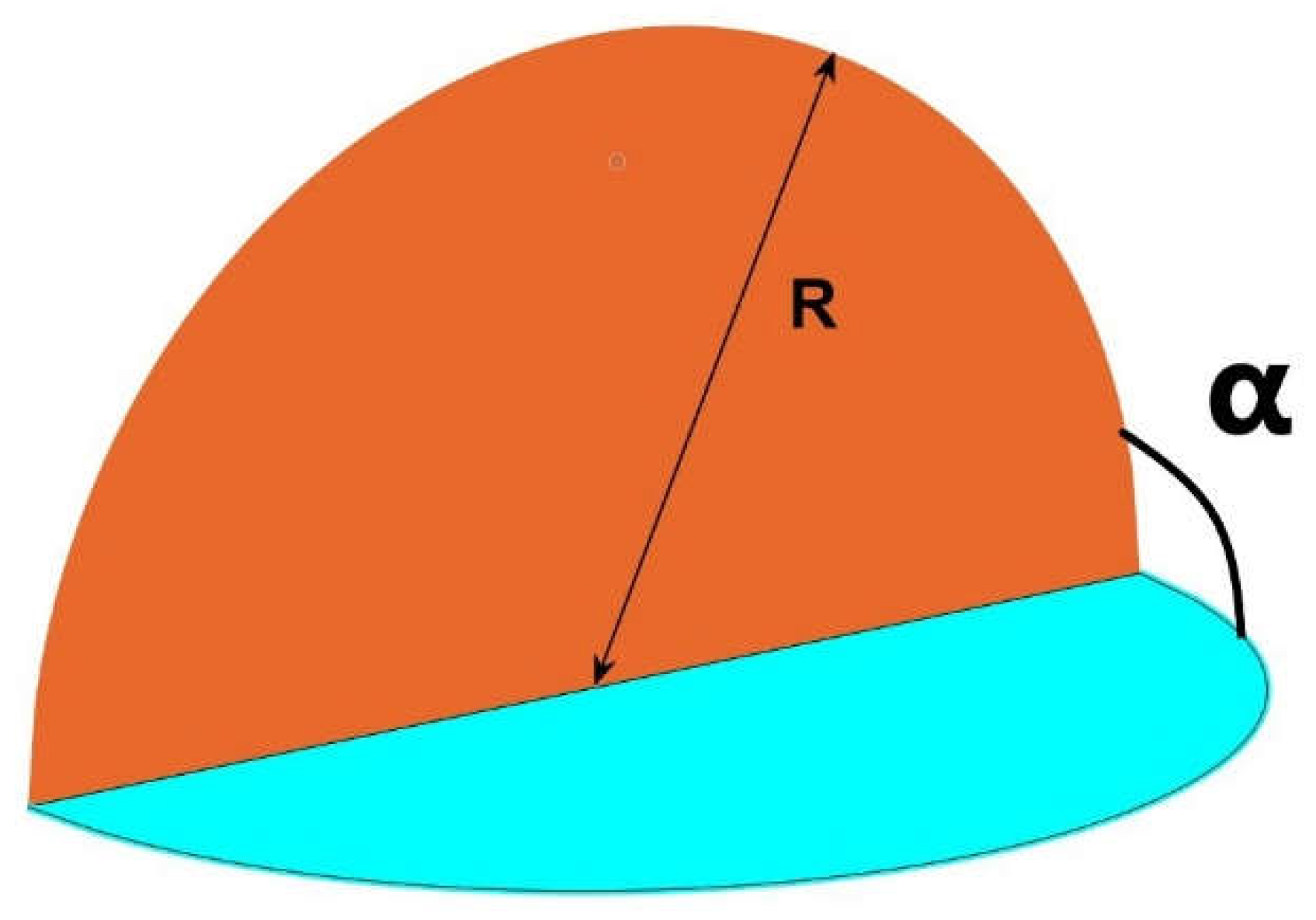
If the emitting surface is not rectangular, for instance a quarter of circle, there are other numerical procedures to which we can resort, for instance we can determine the transfer form factor of a circular sector over a quarter of circle as in
Figure 8 [
44].
6. Complete three-dimensional curved figures
Having clarified the previous section, we would advance towards more complex three-dimensional figures, like for instance sections of the sphere comprised between two quarters of a circle with a common edge. Previously the author has identified the form factors between semicircles (
Figure 14) at different angles sharing a common edge [
45] and circles with a tangent point (
Figure 15) when their angle of connection is variable [
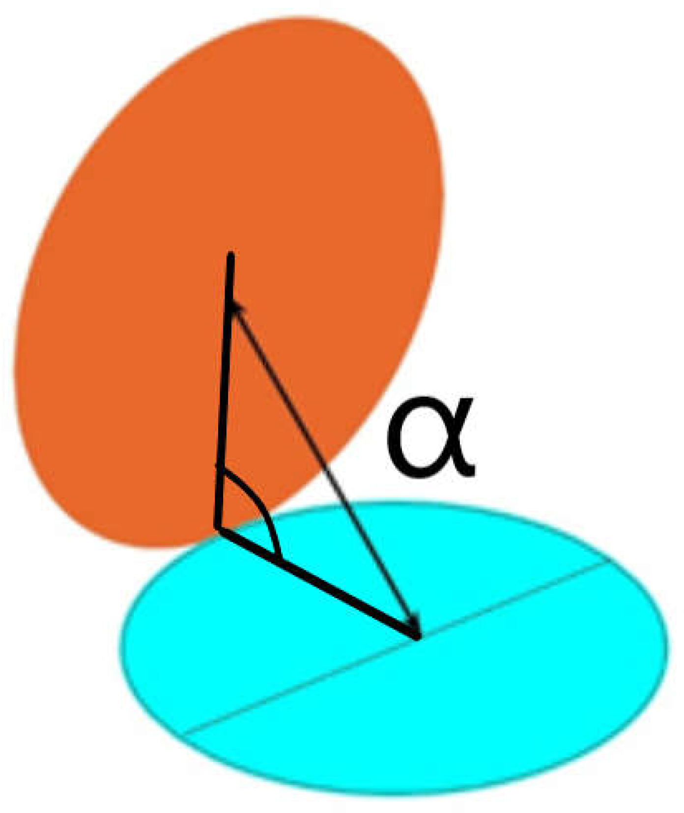
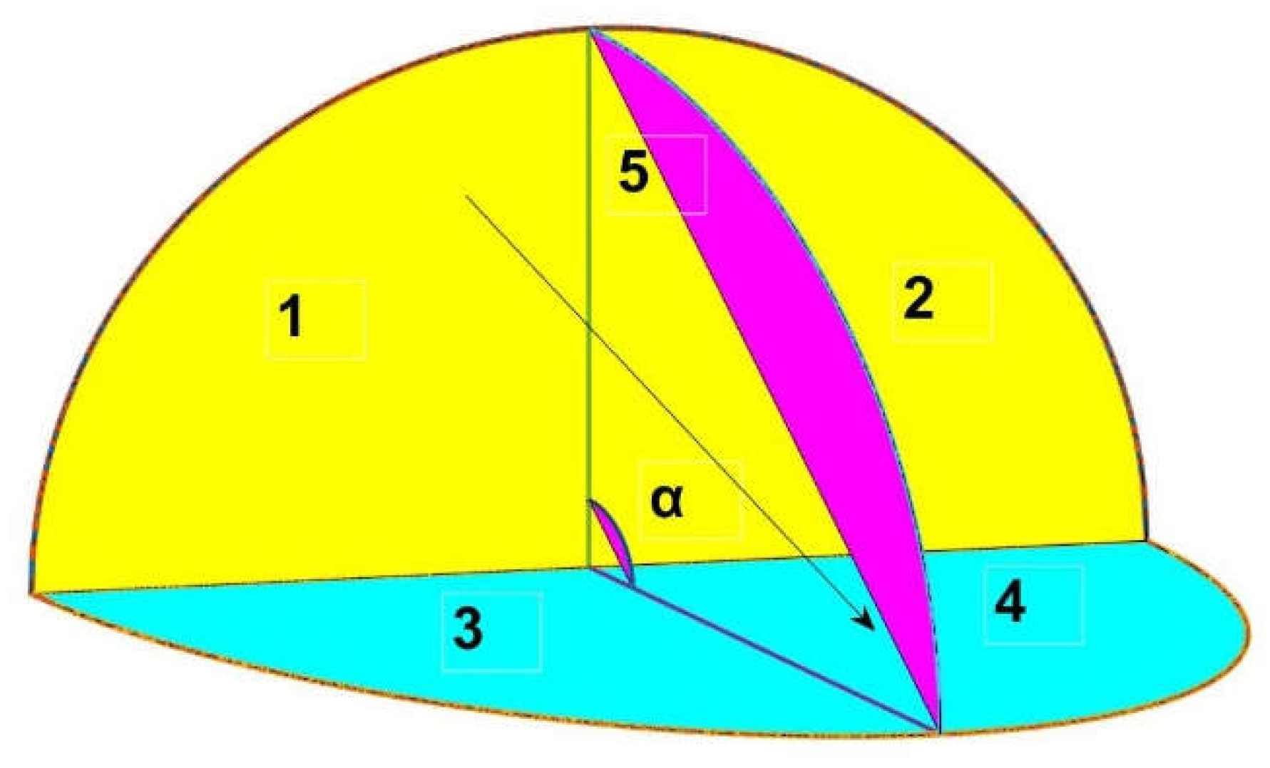
46], but it was not possible to attempt to find the form factors among regions 1 and 3 or 2 and 4 in
Figure 16, even less between alternate quarter of circles like 1 to 4.
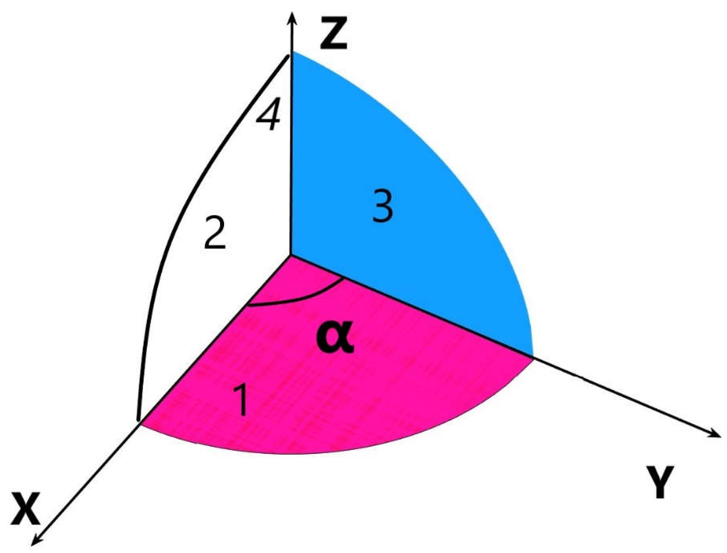
In order to perform such difficult calculation we should shoud start with a trihedron made of two symmetrical quarters of circles, the base is a circular sector of variable angle α and the cover is a fragment of sphere of corresponding area α [
47].
Figure 17.
A trihedron made by symmetrical quarter of circles 2 and 3.
Figure 17.
A trihedron made by symmetrical quarter of circles 2 and 3.
The proposed new postulate for radiative exchange of the two quarters of circles, that we will elucidate below is, (Eq. 61),
As we can see in the figure, surface 4 is the fragment of spherical surface dependent on the angle α, its lateral area is precisely α, the areas of the two symmetrical quarters of circles (named 2 and 3) give an area of π/4 respectively, the area of the circular sector (1) that serves as the basis for the figure is α/2. If α= π/2, we would receive the equilateral trihedron made of three quarters of circle.
Then, as usual, by conservation of radiant energy in an enclosed volume,
We know, by virtue of Cabeza-Lainez first law, that
And F
42 = F
43, as they are symmetrical
From the downwards side, we have (three planar circular sectors),
And F
12 = F
13 , for symmetry reasons,
F
12 , can be found with a very precise approximation by means of the formula described in section 3 for every angle of the circular sector over a quarter of circle (
Figure 18), once we have obtained F
12 , with the help of such numerical procedure based on the integral, we could proceed with the deductions.
And, including the respective values of the areas in 73
And finally we arrive to,
Hower, the respective areas are as follows,
We have demonstrated that it is possible to obtain each and every quantity as a function of F
12 , and conversely F
21 , and more importantly we have demonstrated the new Cabeza-Lainez postulate for quarter of circles with a common edge [
48,
49].
The former Cabeza-Lainez’ law for semicircles was as a function of the angle α,
However, this law was independent of any previously found factor. In terms of p,
For the record, the postulate for whole circles in terms of p is,
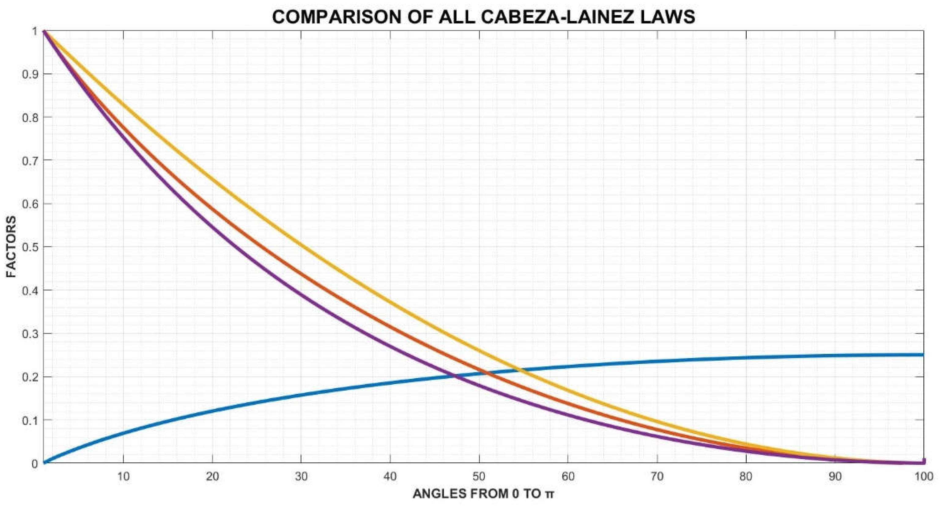
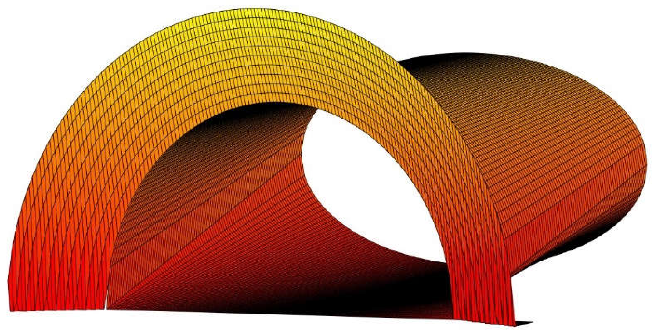
Now, we can compare the three laws obtained with difficulty in
Figure 18
Figure 18.
Graph of comparison of the form-factor postulates, so far obtained, as a function of angle α, yellow colour is for semicircles, orange for quarter of circles and violet for whole circles. Blue colour depicts the evolution of F12, the exchange between a vertical circular sector of angle α and a horizontal fixed quarter of circle.
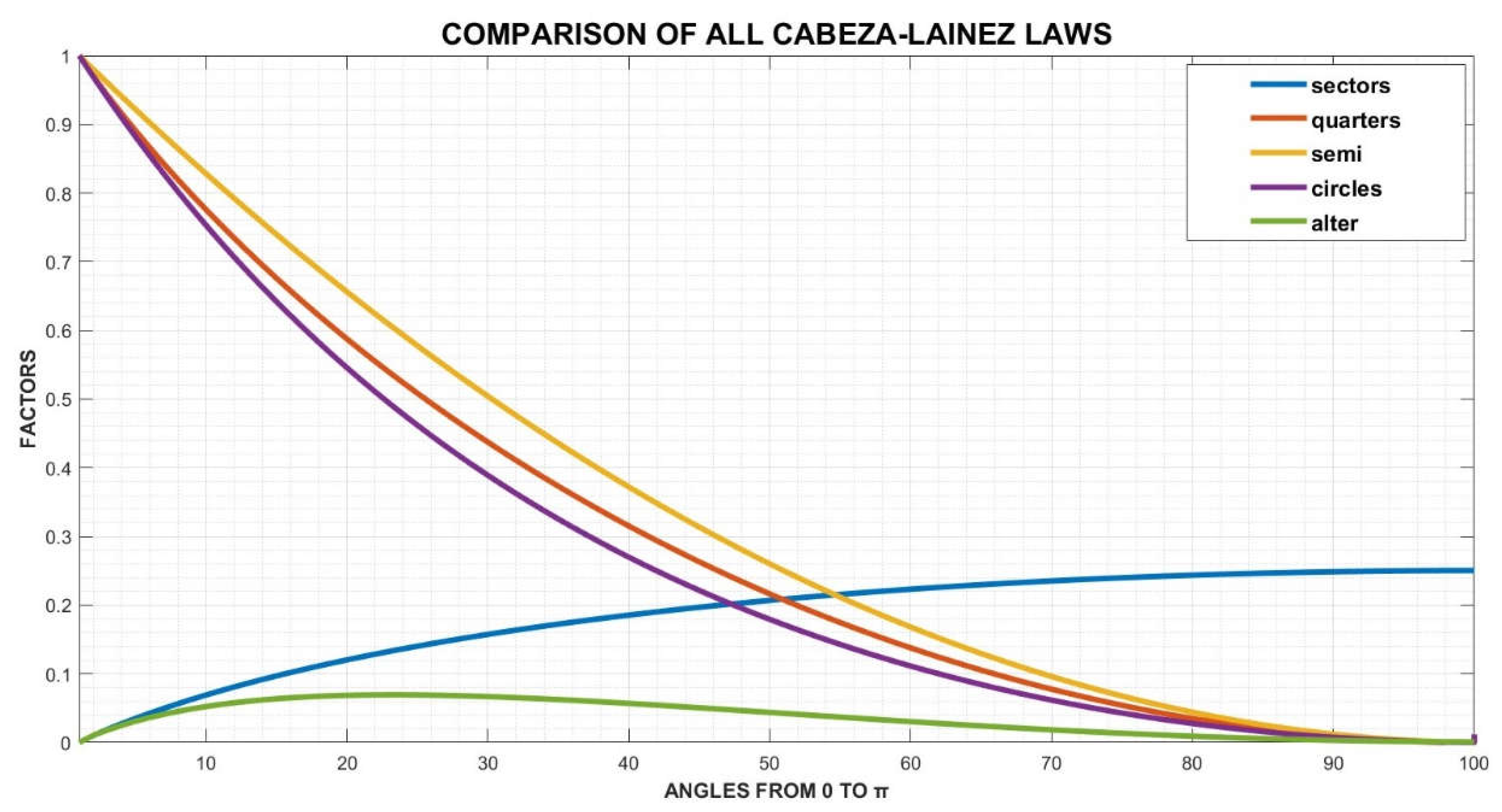
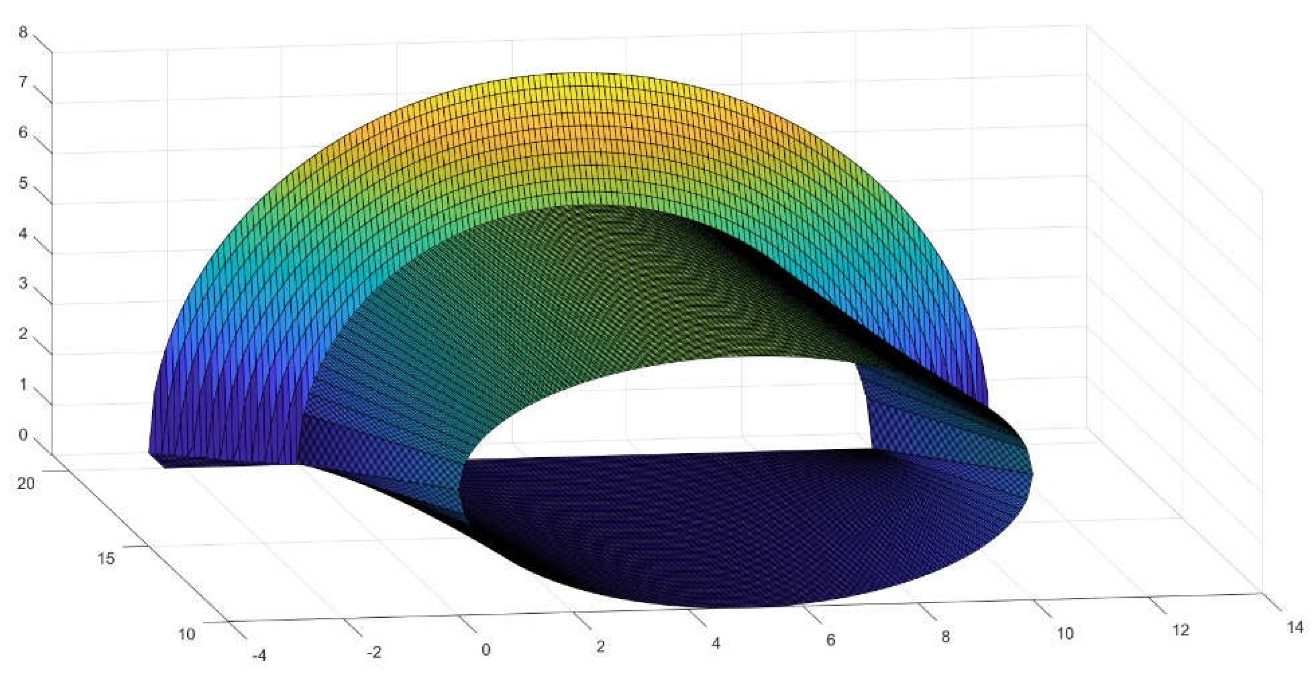
Adding as a novelty the form factors between alternate quarter of circles we receive
Figure 19
Figure 19.
Depiction of the laws discovered adding the alternate quarter of circles in green colour. The maximum for this figure is 0.06935 at point x=23, which means an angle of π/4.34 or 41.4 deg.
Figure 19.
Depiction of the laws discovered adding the alternate quarter of circles in green colour. The maximum for this figure is 0.06935 at point x=23, which means an angle of π/4.34 or 41.4 deg.
6.1. Check for Validity
Demonstration of validity by a simple example [
50], for the quadrant, octave of a sphere or curved trihedron
In this case α= π/2, and as stated previously, we know, by virtue of Cabeza-Lainez first law, that,
Thus, being F
41 and F
42 and F
42 equal and symmetrical,
As A
4 is π/2 and the area of each quadrant is π/4, A
4 =2 A
1
But, as before, F
12 and F
13 are equal and symmetrical, consequently,
And the problem is completely solved since,
With a similar approach, the total form factors can be found for the usual sets of precints, such as prisms or oblique cuboids. Inter-reflection within the so-generated volumes is also an issue that we have to foresee, in the case of triangular prisms we would require a set of five equations with five unknowns which is detailed at the appendix [
36].
For example, when designing and solving inclined slats, the triangles that appear are not right, but usually they come as obtuse or acute angles, in these situation we cannot employ the already solved form factor for perpendicular rectangles [
5], instead we need to resort to different extended formulas developed by the author [] to take into account the exchanges between inclined rectangles.
7. Examples and Applications for Tunnel Openings
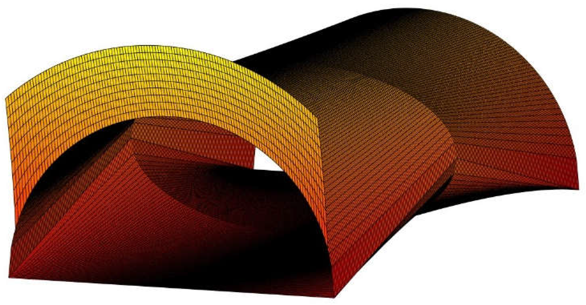
We will try to show some of the relevant possibilities that the form factors, found in this article, offer for different technologies. One of the most important example is the circular opening of tunnels which presents important problem of lighting because of glare, flicker effect and excessive use of energy; necessary to counterbalance the very different levels of lighting at the threshold of the tunnel. The radiative exchange between the entrance opening, usually a semicircle or on other occasions a circular or elliptical segment and the rest of the surfaces inside the tunnel and especially the floor where the vehicles circulate, could not be determined by any means previously to obtain the results that we now possess. In
Figure 20,
Figure 21 and
Figure 22, we present some drawings of one type of innovative tunnels that we have proposed [
42] and whose performance was unavailable to assess before we arrived to the findings hereby exposed.
Having an accurate map of the radiation impinging on the diverse surfaces of the tunnel we are now in the position to control and improve the many undesirable effects that have been registered since the beginning of this technology.
The equations derived from the analysis of
Figure 23 are employed to determine the distribution of radiation especially at the most critical point which is the floor level.
In
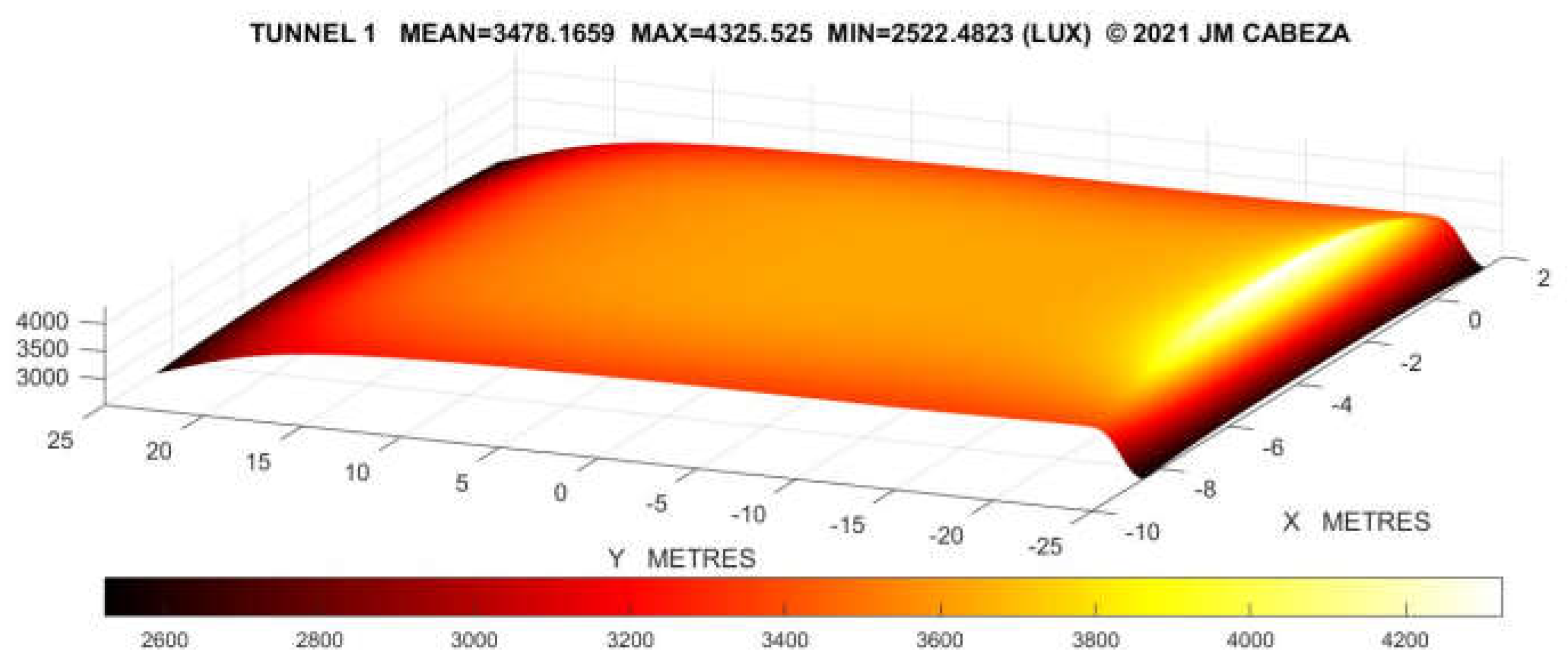
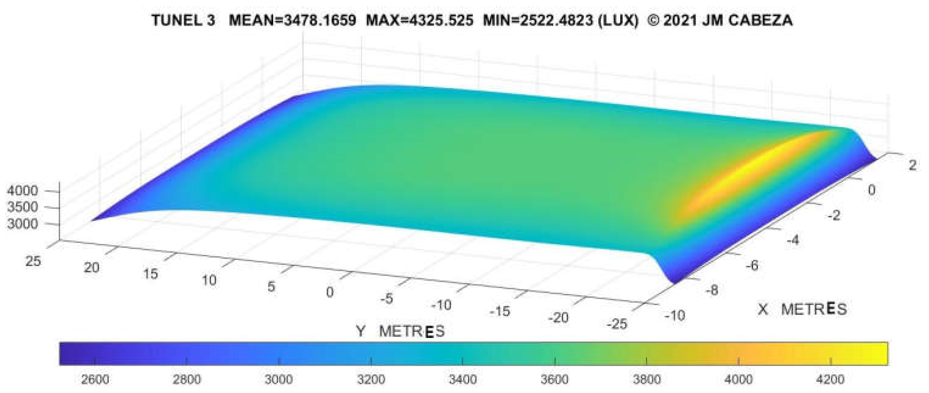
Figure 24 we present some of the early results of radiation as achieved by the combined use of solar ducts and other means of lighting [
43].
These early results prove that the improvements achieved from the detailed knowledge of the new form factor have just begun and more developments can be expected from such significant findings [
44].
8. Conclusion
Throughout this manuscript we have demonstrated by means of accessible calculus operations how to obtain the solution to certain integral equations that provide us with more than five new postulates of radiation between circular sectors, ellipses, circular segments and the interaction between those and figures like the quarter of circle, the triangle and the rectangle. Such effort will undoubtedly contribute to the solution of numerous radiative problems that hindered the development of technology in fields as diverse as of tunneling, solar energies, lighting and aircraft design or construction among others.
Certainly, integral equations are a problematic domain of mathematics but they are mandatory to advance in the many problems of radiative heat transfer as they are frequently colligated to surface emission and demand an exact solution due to the extreme and vital magnitudes which are usually under consideration in this realm.
In the mathematical process followed to improve the level of knowledge in the ralm of radiative transfer it is possible to outline the exactitude and feasibility of the solutions, the introduction of silent variables that only become active in the last phase of integration and the new form of addressing inter-reflections for curved surfaces. Also the combinations with different geometries are a novelty that should not be disregarded.
Semicircles and other derived figures, like circular segments and sectors have been employed in a great number of artifacts and industries since early epochs, now finally are we able to determine with total accuracy their performance under a significant number of demanding situations in radiative heat transfer. However, a detailed logical approach had not been attempted in the past because of the mathematical hindrances arisen in the process. Statistical procedures were almost inapplicable in this case. The solutions provided are especially feasible for the design and retrofit of tunnels, lighting elements from windows to LED emitters and also aircrafts and components affected by radiation and systematically employed in the industry.
The quite relevant novelties that these postulates entail, lie also in the question by which they have been implemented in simulation algorithms by the author. We firmly believe that given the preparedness for application that they present, they will radically transform and sometimes ignite processes based on transfer of radiation whether natural or artificial and amongst them tunnelling, lighting, thermal machinery and radiant power instruments and apparatuses. In this fashion, fundamental issues of radiative heat transfer can be treated in an accurate and assertive manner to boost knowledge on sophisticated forms of energy as radiation undoubtedly is. Thus, we hope that consequences of great significance should by derived from the current research if time provides.
Funding
This research was developed within the frame of the Spanish National project: Smart Built Heritage. Del registro a la simulación digital para inmuebles medievales y modernos (TED2021-129148B-I00).
Acknowledgments
The author wishes to recognize the consistent support and advice of Tomomi Odajima. The article is dedicated to Jose Maria Cabeza Arroyo and Francisca Lainez Robles. Heartfelt thanks go to Inmaculada Rodriguez Cunill their help in several matters. I have been publishing articles on radiative transfer since 1989, I hope, that this is my penultimate measure of writing on the wall: It burned so brightly that blinded us all.
Conflicts of Interest
The authors declare no conflict of interest
In this appendix we will demonstrate in short how we can achieve the same results form the form factor due to the semicircle and the quarter of circle by means of direct integration in Cartesian coordinates.
Let us take a vertical semicircle located at the origin of coordinates, it is limited by an upper circumference which we can take as the limit of the integral (
Figure A1).
Figure A1.
The circumference that limits the semicircle.
Figure A1.
The circumference that limits the semicircle.
By taking for instance the quarter on the right, see
Figure A1, the upper limit of the integral at Z turns into the root,
and the lower limit is the diameter, 0,
The integral equation to solve is the same as before and two different integrals appear [
8], the first one, using the new set limits, would give:
Since all the new expressions are linear for x, it is easy to receive a solution,
We will achieve the following,
Arrangin all results again it yields,
But as a=b, is the radius r of the circle,
Which is exactly the same as the factor presented by the author in section 3 when we had an ange of α=π/2 but then the integral was solved in polar coordinates [
28,
29]. We need to remind that a=b=r and as before x
0=x,
We can easily deduct that for the full semicircle, with an angle α=π), the limits of the second operation would turn b and –b and they will not be zero. In such case the integral equaton produces (Eq. 6)
And reducing in the same manner Eq. 5, we have
If we consider now the half disk as removed at a distance d from the origin the limits of the integral would alter in such a way as to produce a logarithmic integral in the second term.
The initial integral is resolved as before for the limits d+r or d-r as the case may be, giving
While the second part for the values used in Eq. 9, present the form,
And substituting we arrive to,
The final expression amounts to,
An increasing number of functions such as the ellipse or the parabola can be integrated in the same fashion to find new form-factors as the case may be.
In a manner of example if we take the case of an elliptic curve, we could use an upper limit of integration such as ,
With the said limits the first term would provide us with,
Proceeding with the second term we would arrive at,
If
Or Alternatively,
It is necessary to check that the value of the formula is greater than zero when we apply the real values of z and y, because the same nature of the form factor does not permit negative results.
Continuing our reasoning, if we now are able to subtract the form factor of the semicircle from the ellipse provided that the radius r < b, and maintaining the same base field as we had for the ellipse,
Figure A2.
Coordinates for the ellipse minus circle form factor over a horizontal plane.
Figure A2.
Coordinates for the ellipse minus circle form factor over a horizontal plane.
The former represents an important advance of two new postulates which were basically unavailable. [
36].
In the same fashion we could find if desired some factors for fragments of ellipse, or other figures if for instance we subtract, semicircles, triangles or rectangles to the original semi-ellipse, as mentioned through the article.
So far, a great deal of factors
Fij have been obtained, informing us of the primary energy exchange rate set at the bodies and surfaces considered. However, if all of them are enclosed in the same precinct as in
Figure A3, there might be inter-reflections that we need to calculate to solve the problem. The total amount of reflection of each surface
i depending on its radiative properties, will be designed as
ρi [
3,
16].
Figure A3.
The four surfaces involved in the enclosure of an octave of sphere.
Figure A3.
The four surfaces involved in the enclosure of an octave of sphere.
The formulas that give us the amount of reflected radiation as a function of the direct emission are (Eqs. 1 to 3) [
1].
E
dir is the direct amount of energy and E
ref stands for the reflected energy The respective matrixes, F
r and F
d are subsequently defined for a precinct of fours surfaces as the one of Fig. A2.1, in arrays of four rows by five columns as,
Please notice that the final element of the diagonal of matrix Fd, is not zero because surface 4 is curved and therefore F44 has a definite value of 1/8 that solely the author has been capable of finding.
The total result of energy is consequently established as:
In this subtle disregarded manner, the problem of radiant exchanges in space for curved geometry is finally provided for.
References
- Holman, J.P. Heat Transfer. Seventh Edition. Mac Graw Hill. 1995.
- Cabeza-Lainez, J. Fundamentals of luminous radiative transfer: An application to the history and theory of architectural design; Crowley Editions: Seville, Spain, 2006.
- Moon, P.H.; Spencer, D.E. The Photic Field; The MIT Press: Cambridge, MA, USA, 1981.
- Subramaniam, S.; Hoffmann, S.; Thyageswaran, S.; Ward, G. Calculation of View Factors for Building Simulations with an Open-Source Raytracing Tool. Appl. Sci. 2022, 12, 2768. [CrossRef]
- Modest, M.F. View Factors. In Radiative Heat Transfer, 3rd ed.; Academic Press: Cambridge, MA, USA, 2013; pp. 129–159.
- Hensen, J.L.M.; Lamberts, R. Building Performance Simulation for Design and Operation, 2nd ed.; Routledge: London, UK, 2019; ISBN 9781138392199.
- Moon P.H. The scientific basis of illuminating engineering. New York: McGraw-Hill Book Co. Dover Publications; 1963.
- Feingold, A. Radiant-Interchange configuration factors between various selected plane surface. Proceedings of the Royal Society of London. Series A, Mathematical and Physical Sciences, May 3, 1966, Vol. 292, No. 1428 (May 3, 1966), pp. 51-60 Published by: Royal Society Stable URL: https://www.jstor.org/stable/2415616.
- Howell, John R, Robert Siegel and M. Pinar Mengüç, Thermal Radiation Heat Transfer, 5th ed., Taylor and Francis/CRC, New York, 2010.
- Cabeza-Lainez, J. Innovative Tool to Determine Radiative Heat Transfer Inside Spherical Segments. Appl. Sci. 2023, 13, 8251. [CrossRef]
- Hamilton, D.C.; Morgan, W. Radiant-Interchange Configuration Factors. NASA. 1952. Online version: https://ntrs.nasa.gov/citations/19930083529 (accessed on 9 May 2023).
- Cabeza-Lainez, J. Finding the Exact Radiative Field of Triangular Sources: Application for More Effective Shading Devices and Windows. Appl. Sci. 2023, 13, 11318. [CrossRef]
- Sasaki, K. View factor of a spheroid and an ellipse from a plate element. Journal of Quantitative Spectroscopy and Radiative Transfer, Volume 326, 2024, 109102. ISSN 0022-4073. [CrossRef]
- Schröder, P. Hanrahan, P. On the Form Factor between Two Polygons. SIGGRAPH ‘93: Proceedings of the 20th annual conference on computer graphics and interactive techniques. September 1993. Pages 163-164. [CrossRef]
- Cabeza-Lainez, J. New configuration factors for curved surfaces. J. Quant. Spectrosc. Radiat. Transf. 2013, 111, 71-80.
- Song, Y., Zhang, T., Qi, F. A correction method for calculating sky view factor in urban canyons using fisheye images. Building and Environment, Volume 262, 2024, 111834, ISSN 0360-1323. [CrossRef]
- Lambert J.H. Photometria. sive de mensura et gradibus Luminis, Colorum et Umbrae. In: DiLaura D, editor. IESNA. (2001); 1764.
- Hilbert, D. Cohn-Vossen, S. Geometry and the Imagination. AMS (American Mathematical Society) Chelsea Publishing. Providence. Rhode Island; 1990.
- Camaraza-Medina, Y., Hernandez-Guerrero, A., and Luviano-Ortiz, J. L., 2023, View factor for radiative heat transfer calculations between triangular geometries with common edge, J. Thermal Analysis and Calorimetry. [CrossRef]
- A catalogue of radiation heat transfer configuration factors. J. R. Howell. University of Texas at Austin. http://www.thermalradiation.net/indexCat.html.
- Cabeza Lainez J. Scientific designs of sky-lights. In: Proceedings of the Conference on passive and low energy architecture (PLEA). Brisbane, Australia; 1999.
- Howell, J. R. A catalogue of radiation heat transfer configuration factors. Factor C-43b. http://www.thermalradiation.net/sectionc/C-43b.html.
- Howell, J. R. A catalogue, factor C-140b. http://www.thermalradiation.net/sectionc/C-140b.html.
- Cabeza Lainez J. Solar radiation in buildings. Transfer and simulation procedures. In: Elisha B, editor. Solar radiation. InTech 2012. E. Babatunde. On-line version available at /intechopen.com. ISBN:978-953-51-0384-4; 2012. [chapter 16].
- Howell J. R., Siegel R., Pinar M. M. Radiative transfer configuration factor catalogue: a listing of relations for common geometries. J. Quanti. Spectrosc. Radiat. Transfer 2011; 112: 910–2.
- Camaraza-Medina, Y., 2023: “Polynomial cross-roots application for the exchange of radiant energy between two triangular geometries,” Ingenius, Revista de Ciencia y Tecnología, N. 30, pp. 29-41. doi.org/10.17163/ings.n30.2023.03.
- Fock V. Zur Berechnung der Beleuchtungsstärke. St. Petersburg: Optisches Institut; 1924.
- Cabeza-Lainez, J. (2023). The Potential of Architectural Forms Derived from the Conoid: Ruled Surfaces in Parametric Design and Construction. In: Architecture Inspired by Nature. Springer, Cham. [CrossRef]
- Feingold, A. A new look at radiation configuration factors between disks. J. Heat Transfer. 1978, 100(4): 742-744. [CrossRef]
- Cabeza-Lainez, J.M.; Pulido-Arcas, J.A. New Configuration Factor between a Circle, a Sphere and a Differential Area al Random Positions. J. Quant. Spectrosc. Radiat. Transf. 2013, 129, pp. 272-276. [CrossRef]
- Cabeza-Lainez, J.M. Rodriguez-Cunill, I. The Problem of Lighting in Underground Domes, Vaults, and Tunnel-Like Structures of Antiquity; An Application to the Sustainability of Prominent Asian Heritage (India, Korea, China). Sustainability 2019, 11, 5865. [CrossRef]
- Cabeza-Lainez, J. A New Principle for Building Simulation of Radiative Heat Transfer in the Presence of Spherical Surfaces. Buildings 2023, 13, 1447. [CrossRef]
- Cabeza-Lainez, J.M. Rodríguez-Cunill, I. Prevention of Hazards Induced by a Radiation Fireball through Computational Geometry and Parametric Design. Mathematics 2022, 10, 387. [CrossRef]
- Howell, J. R. A catalogue of radiation heat transfer configuration factors. Factor C-43a. http://www.thermalradiation.net/sectionc/C-43a.html.
- Salguero-Andujar, F.; Cabeza-Lainez, J.-M. New Computational Geometry Methods Applied to Solve Complex Problems of Radiative Transfer. Mathematics 2020, 8, 2176. [CrossRef]
- Nußelt, W. Graphische Bestimmung des Winkelverhältnisses bei der Wärmestrahlung. Z. Ver. Dtsch. Ing. 1928, 72, 673.
- Naraghi, M. H. N. Radiation View Factors from Differential plane sources to disks- A general formulation. 1988. Technical notes of the American Institute of Aeronautics and Astronautics Journal. Vol 2. No.3. 3 Pages.
- MacAllister A.S. Graphical solutions of problems involving plane surface lighting sources. Lighting world. 1911; 56:135.
- Cabeza-Lainez, J. A New Principle for Building Simulation of Radiative Heat Transfer in the Presence of Spherical Surfaces. Buildings 2023, 13, 1447. [CrossRef]
- Howell, J. R. A catalogue, factor C-140a. http://www.thermalradiation.net/sectionc/C-140a.html.
- Howell, J. R. A catalogue, factor C-140c .http://www.thermalradiation.net/sectionc/C-140c.html.
- Howell, J. R. A catalogue, factor C-140d. http://www.thermalradiation.net/sectionc/C-140d.html.
- Howell, J. R. A catalogue, References. http://www.thermalradiation.net/references.html.
- Naraghi, M.H.N. Radiative View Factors from Spherical Segments to Planar Surfaces. J Thermophys Heat Transf 1988, 2, 4, pp. 373-375. [CrossRef]
- Chung, B.T.F.; Naraghi, M.H.N. Some Exact Solutions for Radiation View Factors from Spheres. AIAA J. 1981, 19, 1077–108.
- Sasaki, K.; Sznajder, M. Analytical view factor solutions of a spherical cap from an infinitesimal surface. Int. J. Heat Mass Transf. 2020, 163, 120477.
- Cabeza-Lainez, J. Architectural Characteristics of Different Configurations Based on New Geometric Determinations for the Conoid. Buildings.2022, 12, 10. [CrossRef]
- Howell, J. R. A catalogue, factor C-19. http://www.thermalradiation.net/sectionc/C-19.html.
- Howell, J. R. A catalogue, factor C-25. http://www.thermalradiation.net/sectionc/C-25.html.
- McAdam, D.W.; Khatry, A.K.; and Iqbal, M., 1971, “Configuration Factors for Greenhouses,” Am. Soc. Ag. Engineers, vol. 14, no. 6, pp. 1068-1092, Nov.-Dec.
- Mathiak, F.U., 1985, “Berechnung von konfigurationsfactoren polygonal berandeter ebener gebiete (Calculation of form-factors for plane areas with polygonal boundaries),” Warme- und Stoff bertragung, vol. 19, no. 4, pp. 273-278.
- Minning, C.P., 1976, “Calculation of shape factors between parallel ring sectors sharing a common centerline,” AIAA J., vol. 14, no. 6, pp. 813-815.
Figure 1.
Radiative exchanges for a pair of freely evolving surfaces, namely A1 and A2.
Figure 1.
Radiative exchanges for a pair of freely evolving surfaces, namely A1 and A2.
Figure 2.
The vertical semicircle used to find the form-factor on the plane XY.
Figure 2.
The vertical semicircle used to find the form-factor on the plane XY.
Figure 3.
Depiction of the semicircle and its axis for the integration proccess.
Figure 3.
Depiction of the semicircle and its axis for the integration proccess.
Figure 4.
Depiction of the circular sector and its central angle to find the foorm factor.
Figure 4.
Depiction of the circular sector and its central angle to find the foorm factor.
Figure 5.
Depiction of the regions that appear in the quarter of circule after being cut by a triangle and/or regtangle.
Figure 5.
Depiction of the regions that appear in the quarter of circule after being cut by a triangle and/or regtangle.
Figure 6.
The form factor due to vertical and horizontal circular segments obtained by subtracting a rectangle or a triangle (as the case may be) to the semicircle.
Figure 6.
The form factor due to vertical and horizontal circular segments obtained by subtracting a rectangle or a triangle (as the case may be) to the semicircle.
Figure 7.
The form factor from a ring of two concentric circles.
Figure 7.
The form factor from a ring of two concentric circles.
Figure 8.
A circular sector of angle α, over a quarter of circle.
Figure 8.
A circular sector of angle α, over a quarter of circle.
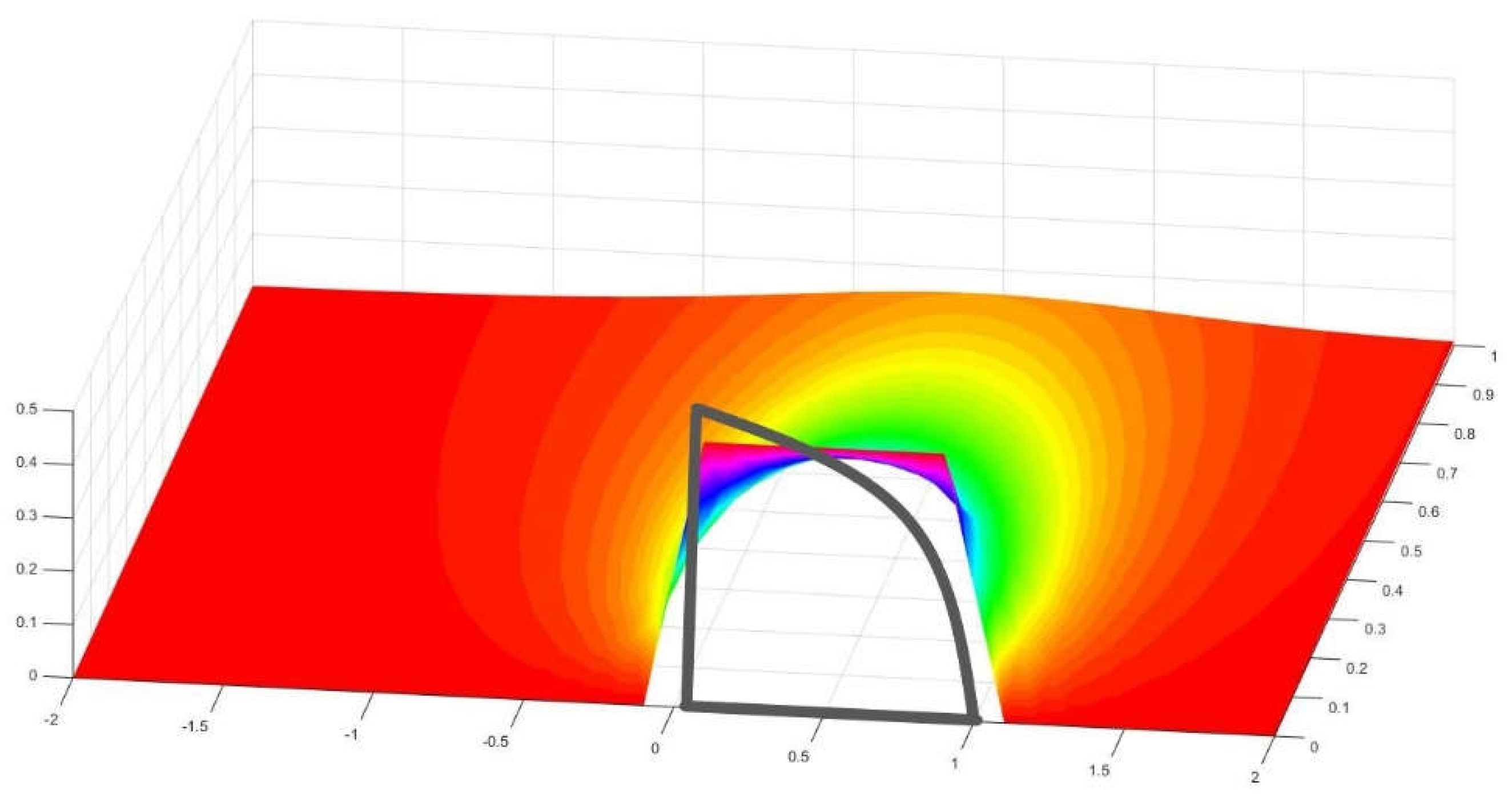
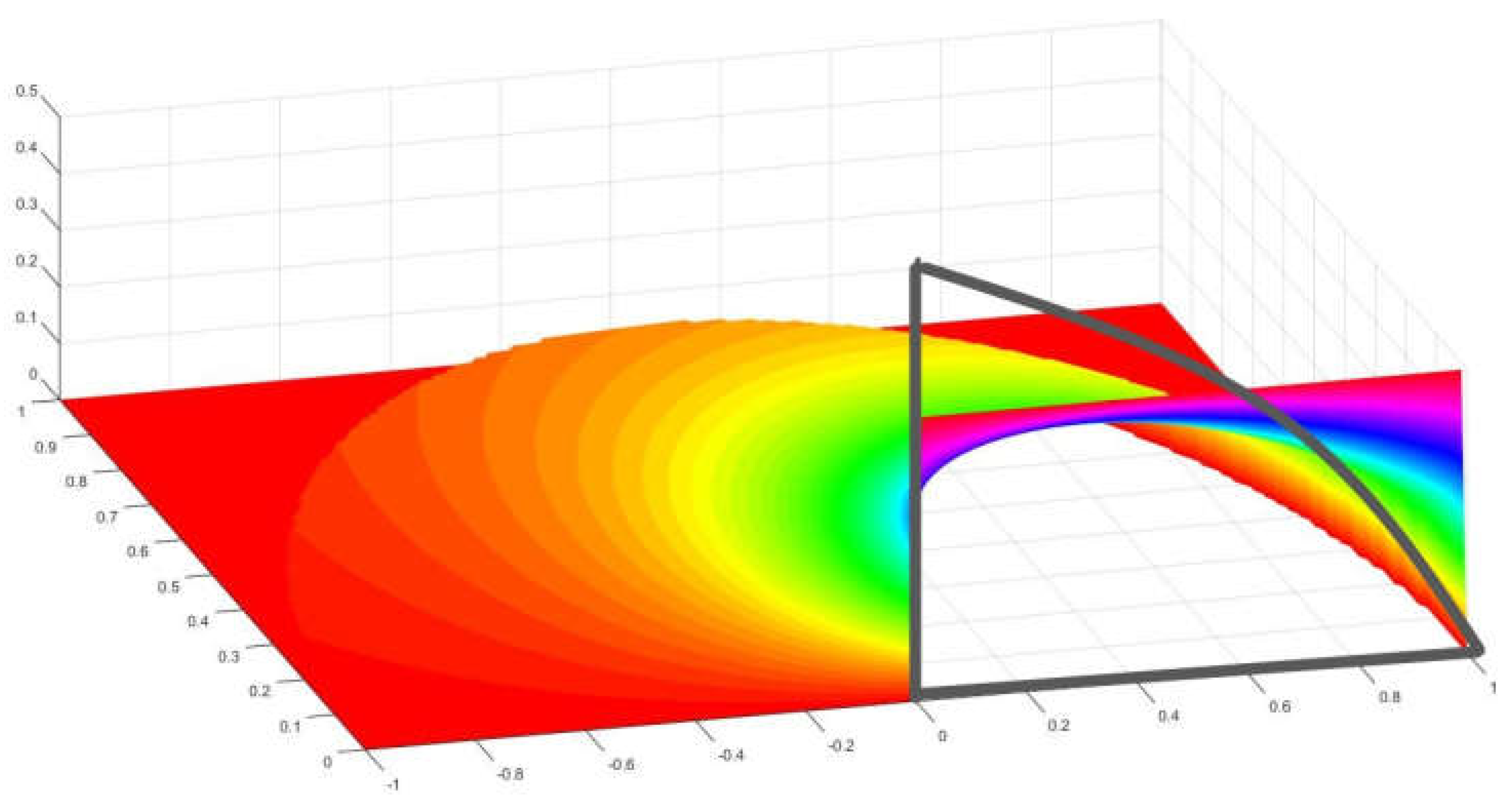
Figure 9.
View of the nephograph produced by a quarter of circle over a rectangle of 4 by 1 units. The values of the form factor at each point are registered in the Z axis.
Figure 9.
View of the nephograph produced by a quarter of circle over a rectangle of 4 by 1 units. The values of the form factor at each point are registered in the Z axis.
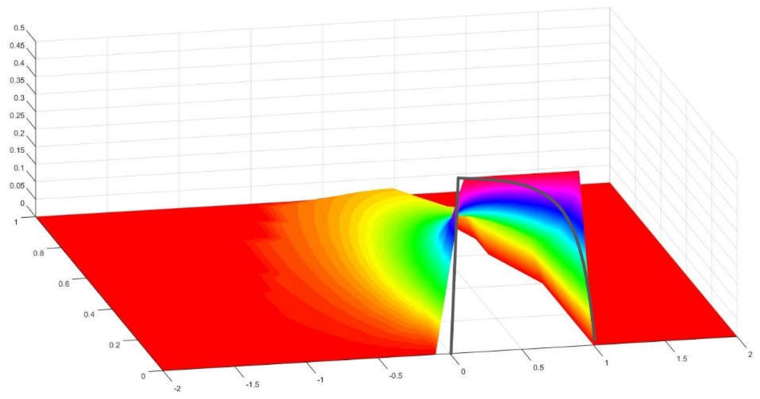
Figure 10.
Another perspective of the graph in
Figure 9.
Figure 10.
Another perspective of the graph in
Figure 9.
Figure 11.
Nephograph of a quarter of circle impinging over a rectangle of 2 by 1 units.
Figure 11.
Nephograph of a quarter of circle impinging over a rectangle of 2 by 1 units.
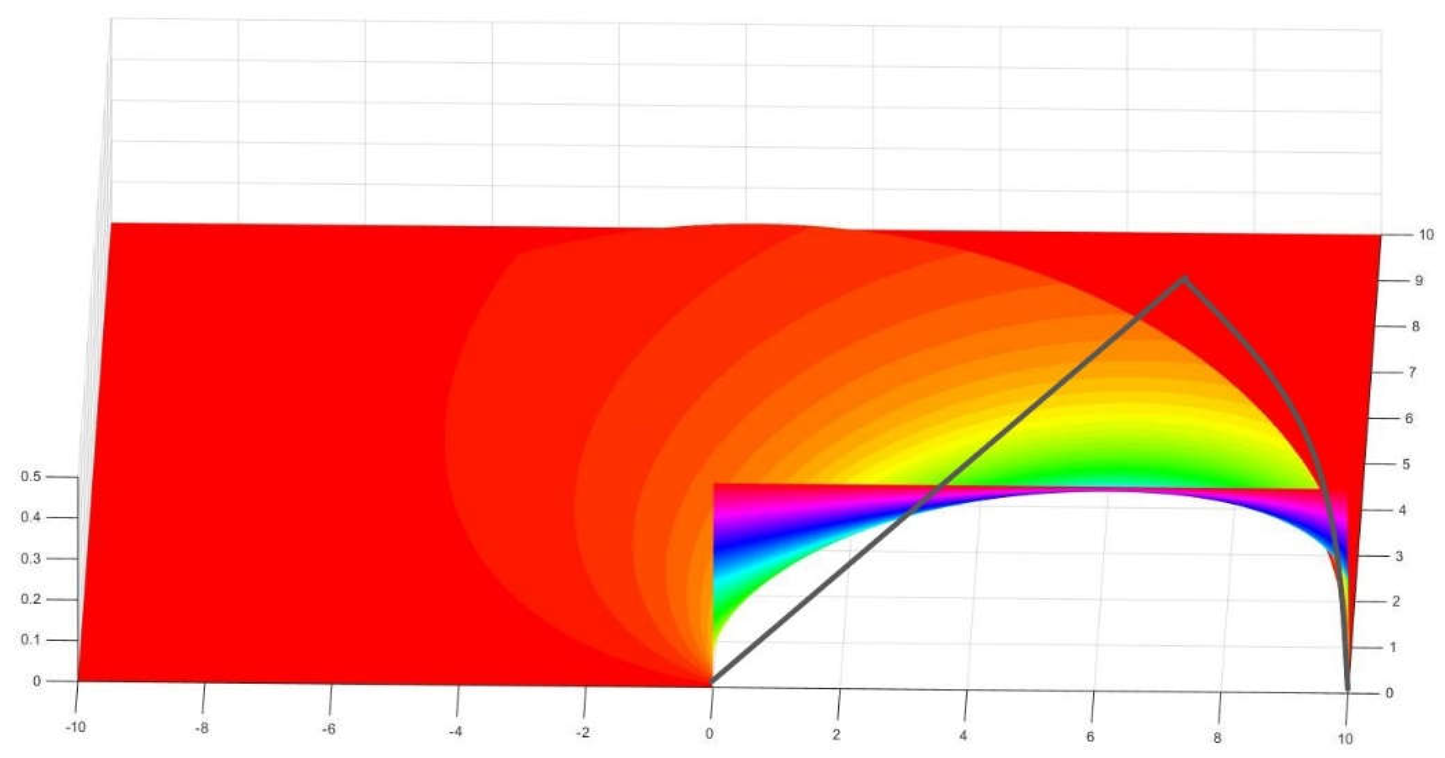
Figure 12.
An octave of circle over a rectangle of 10 by 10 units.
Figure 12.
An octave of circle over a rectangle of 10 by 10 units.
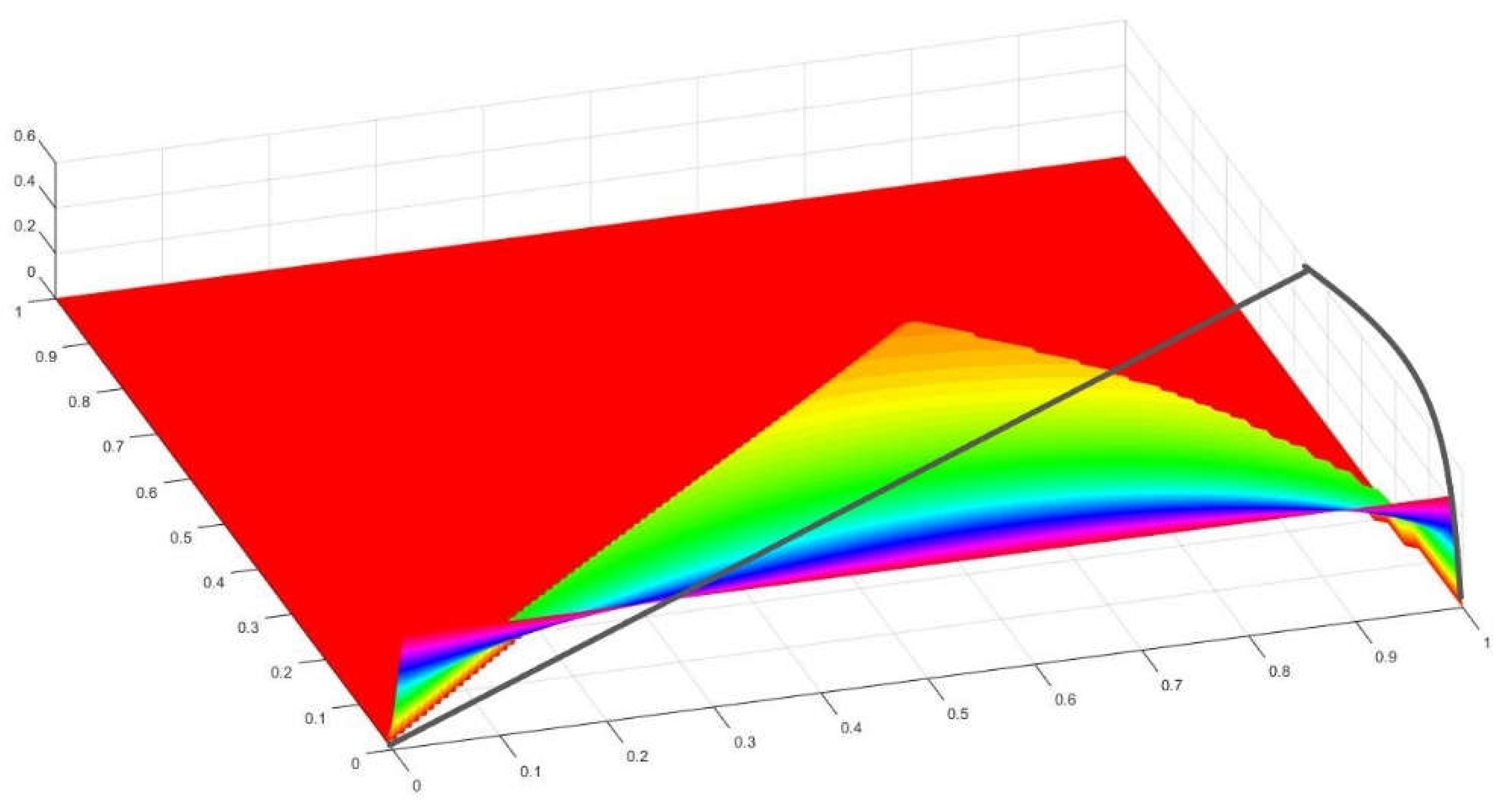
Figure 13.
An octave of a circle on a square of 1 by 1 units.
Figure 13.
An octave of a circle on a square of 1 by 1 units.
Figure 14.
Semicircles of the same radius with a common edge forming an angle α.
Figure 14.
Semicircles of the same radius with a common edge forming an angle α.
Figure 15.
Circles with a tangent point comprising an angle α.
Figure 15.
Circles with a tangent point comprising an angle α.
Figure 16.
New Exchange factors between quarter of circles forming an angle α.
Figure 16.
New Exchange factors between quarter of circles forming an angle α.
Figure 20.
Front entrance to a road or railway tunnel proposed by the author.
Figure 20.
Front entrance to a road or railway tunnel proposed by the author.
Figure 21.
Rear wiew from the inside of the tunnel.
Figure 21.
Rear wiew from the inside of the tunnel.
Figure 22.
Perspective view of two sectors of the projected tunnel.
Figure 22.
Perspective view of two sectors of the projected tunnel.
Figure 23.
Depiction of the geometry of a semicircle over a horizontal quarter of circle both centerd on the origin.
Figure 23.
Depiction of the geometry of a semicircle over a horizontal quarter of circle both centerd on the origin.
Figure 24.
Results of radiation distribution on the floor of the tunnel in
Figure 20.
Figure 24.
Results of radiation distribution on the floor of the tunnel in
Figure 20.
Figure 25.
Results of radiation distribution on the tunnel.
Figure 25.
Results of radiation distribution on the tunnel.
|
Disclaimer/Publisher’s Note: The statements, opinions and data contained in all publications are solely those of the individual author(s) and contributor(s) and not of MDPI and/or the editor(s). MDPI and/or the editor(s) disclaim responsibility for any injury to people or property resulting from any ideas, methods, instructions or products referred to in the content. |
© 2024 by the authors. Licensee MDPI, Basel, Switzerland. This article is an open access article distributed under the terms and conditions of the Creative Commons Attribution (CC BY) license (http://creativecommons.org/licenses/by/4.0/).
