Submitted:
14 August 2024
Posted:
15 August 2024
You are already at the latest version
Abstract
Keywords:
1. Introduction
2. Materials and Methods
2.1. Determination of Plasticizing Curves
2.2. Testing of Energy-Absorbing Structures
2.2.1. Manufacturing
2.2.2. Crashworthiness Testing
2.3. FEM Simulation
2.3.1. Material Model
2.3.2. Boundary Conditions
3. Results
3.1. Determination of Plasticizing Curves
3.2. Testing of Energy-Absorbing Structures
3.2.1. Manufacturing
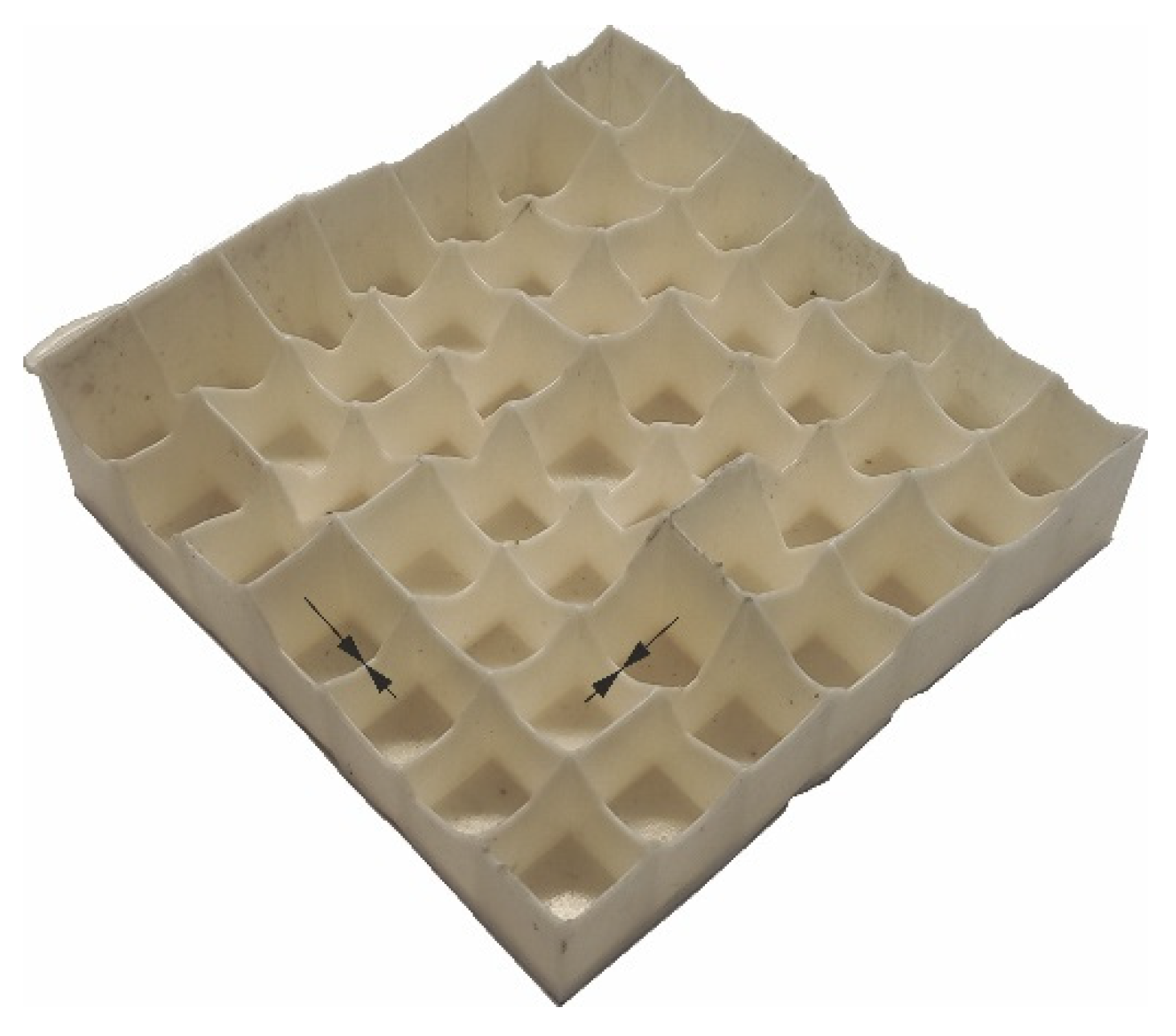
| Material (PBAT blends) |
Minimal gap [mm] |
Material (TPS blends) |
Minimal gap [mm] |
|---|---|---|---|
| PLA50PBAT50 | 0.22 ± 0.01 | PLA50TPS50 | 0.23± 0.01 |
| PLA30PBAT70 | 0.18 ± 0.02 | PLA30TPS70 | 0.20 ± 0.02 |
| PLA15PBAT85 | 0.15 ± 0.01 | PLA15TPS85 | 0.17 ± 0.02 |
3.2.2. Crashworthiness Testing
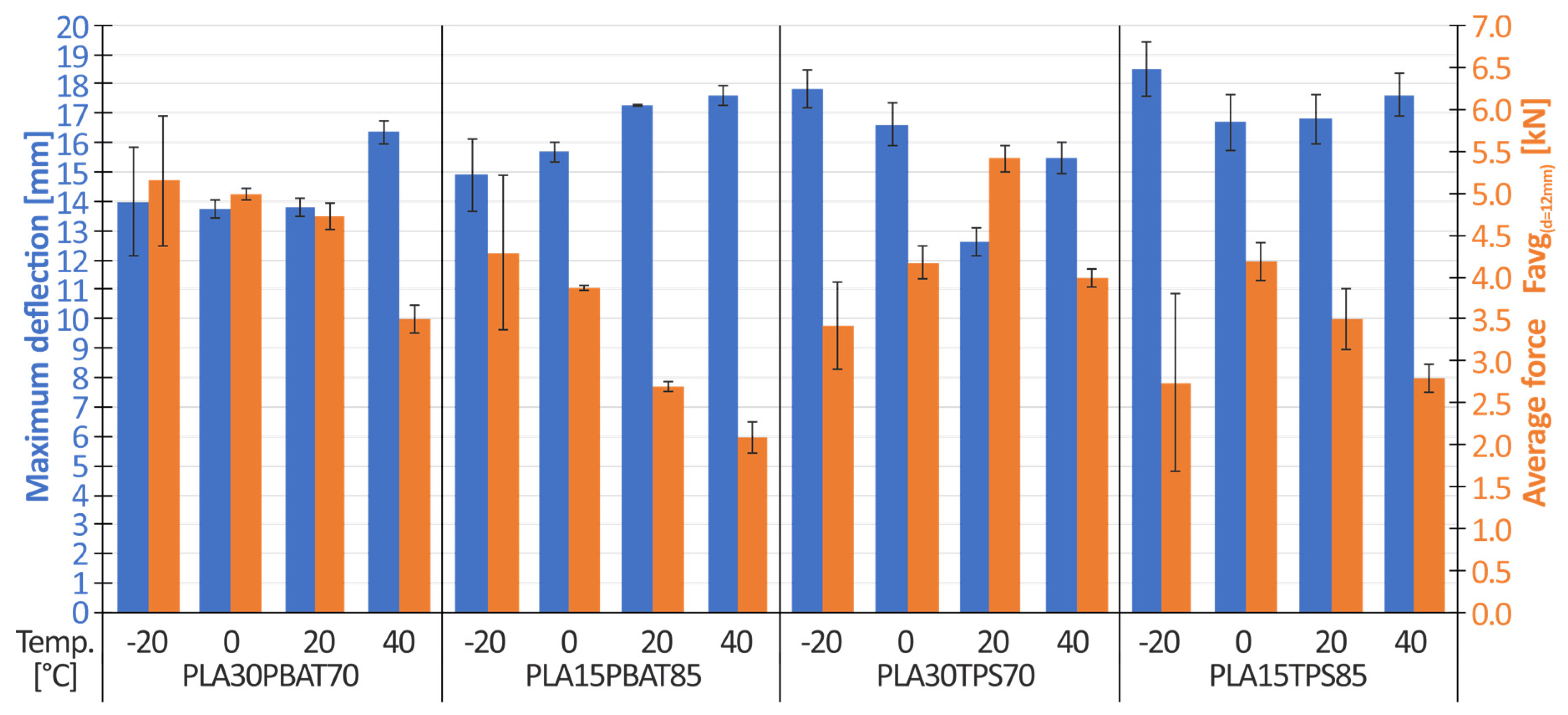
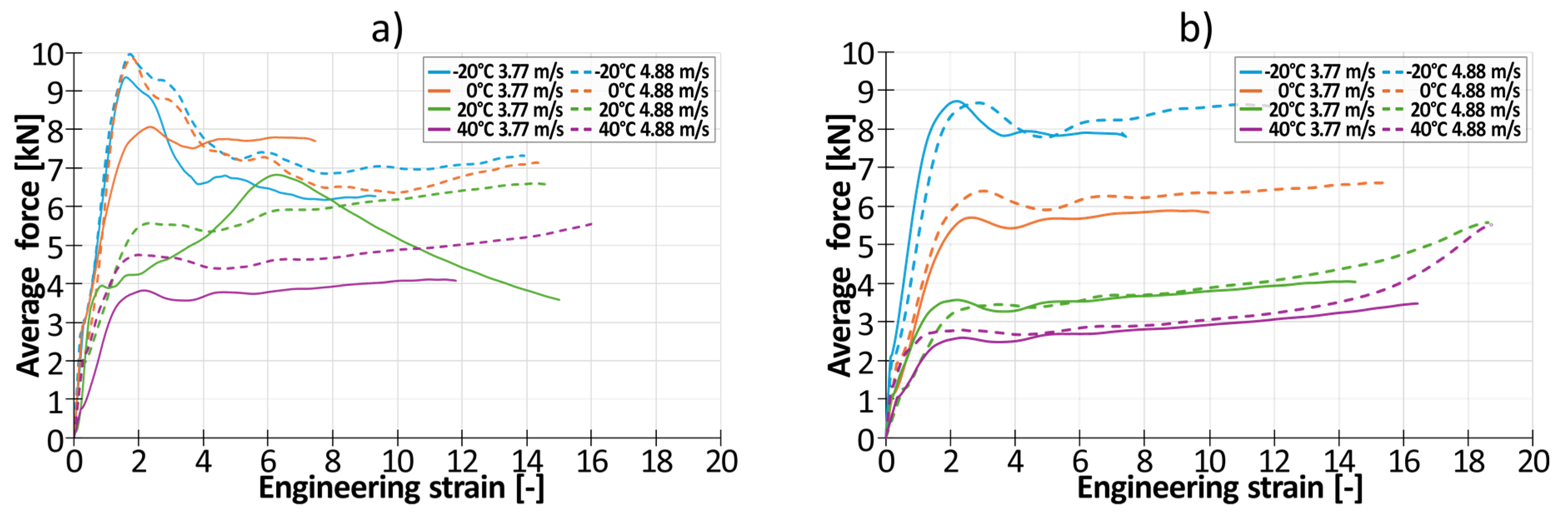
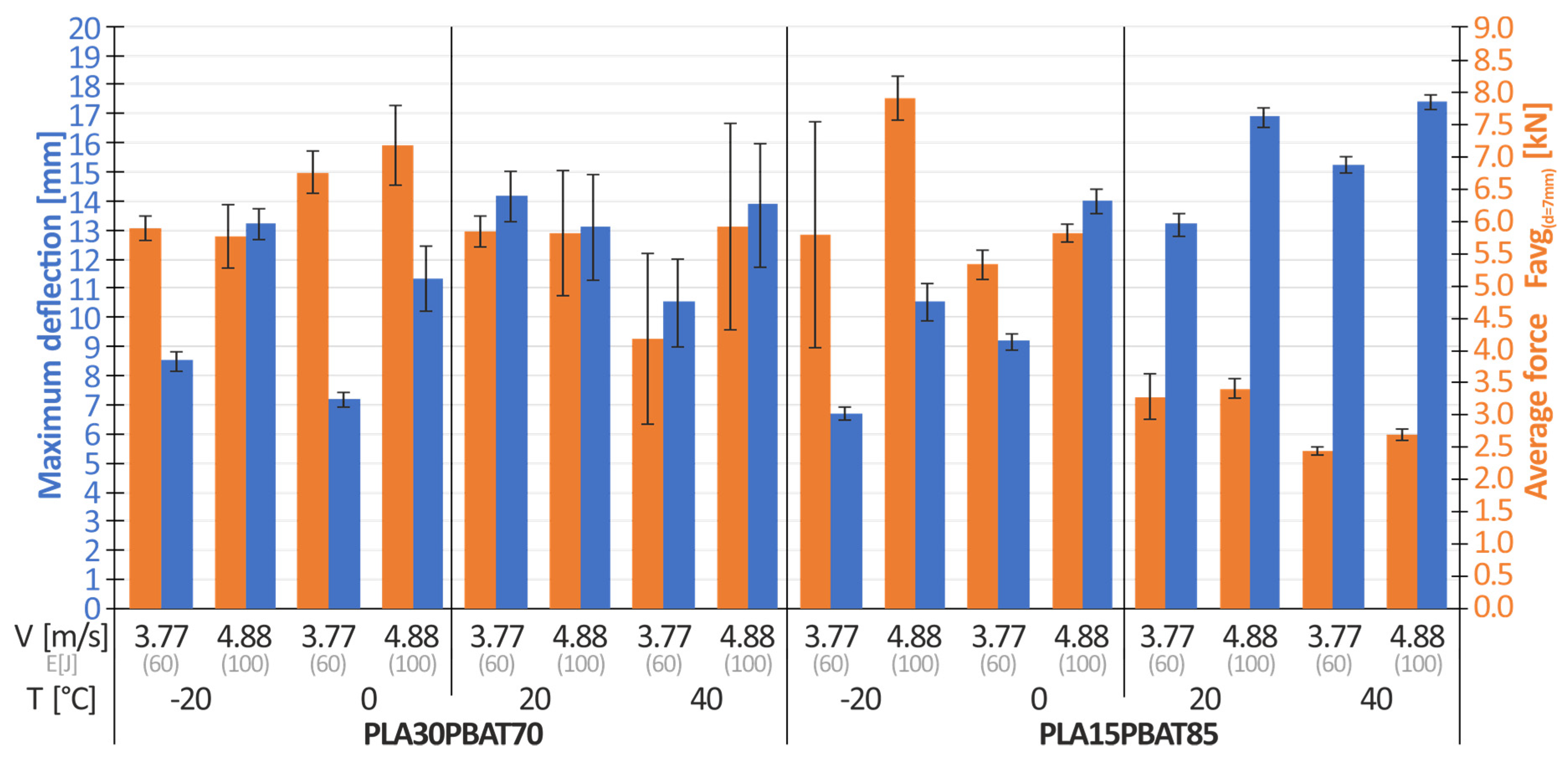
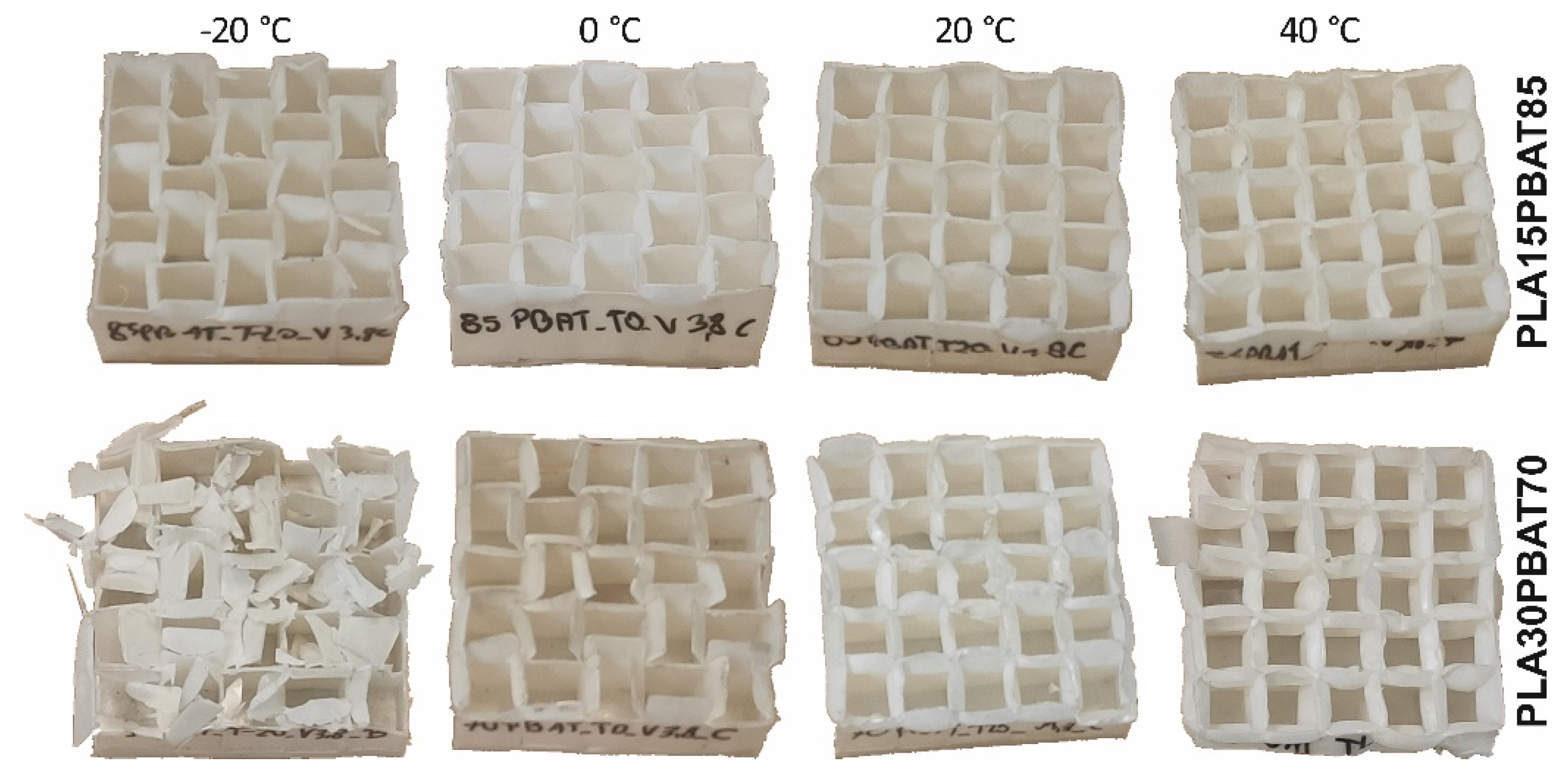
- There is a clear influence of the amount of plasticizer in the case of PLA/PBAT mixtures. The PLA15PBAT85 mixture have a deflection greater by approximately 7% (for T = -20°C), 14% (for T = 0°C), 25% (for T = 20°C), and 8% (for T = 40° C) relative to the PLA30PBAT70 mixture. For both mixtures, the maximum deflection increases as the material temperature increases.
- Samples made of the PLA30PBAT70 mixture achieve a higher value of the average crushing force Favg(d = 12 mm) at a deflecion of 12 mm, compared to samples made of the PLA15PBAT85 material. The differences intensify as the temperature increases. The ratio of the average force Favg(d = 12 mm) of the PLA30PBAT70 material to the average force Favg(d = 12 mm) of the PLA15PBAT85 material is respectively: 1.21 (for T = -20°C), 1.35 (for T = 0°C), 1.75 (for T = 20°C), and 1.59 (for T = 40°C).
- Different characteristics of TPS and PBAT softening additives were noticed. In the case of temperatures ranging from -20°C to 0°C, comparing the same amount of TPS and PBAT additives (PLA30TPS70 vs. PLA30PBAT70 and PLA15TPS85 vs. PLA15TBAT85), materials with the addition of TPS have several percent greater deflection and a lower value of the average crushing force Favg(d = 12 mm) compared to materials based on PBAT. In the case of temperatures ranging from 20°C to 40°C, the opposite situation occurs: materials with the addition of TPS are characterized by lower maximum deflection and greater crushing force.
3.3. FEM Simulation
3.3.1. Materials Model
| PLA15PBAT85material model | Param. | Value[-] | σ[-] | Value[-] | R2[-] |
|---|---|---|---|---|---|
| Cowper-Symonds |
D p |
5647 4,85 |
D0.95 p0.95 |
±432 ±0,14 |
0.88 |
| Johnson-Cook simpl. |
A B C n |
19.90 17.27 0.0565 1.2601 |
A0.95 B0.95 C0.95 n0.95 |
±0.21 ±0.23 ±0.0008 ±0.0451 |
0.92 |
3.3.2. Numerical Simulation of Dynamic Compression Test of Energy-Absorbing Structure
4. Summary
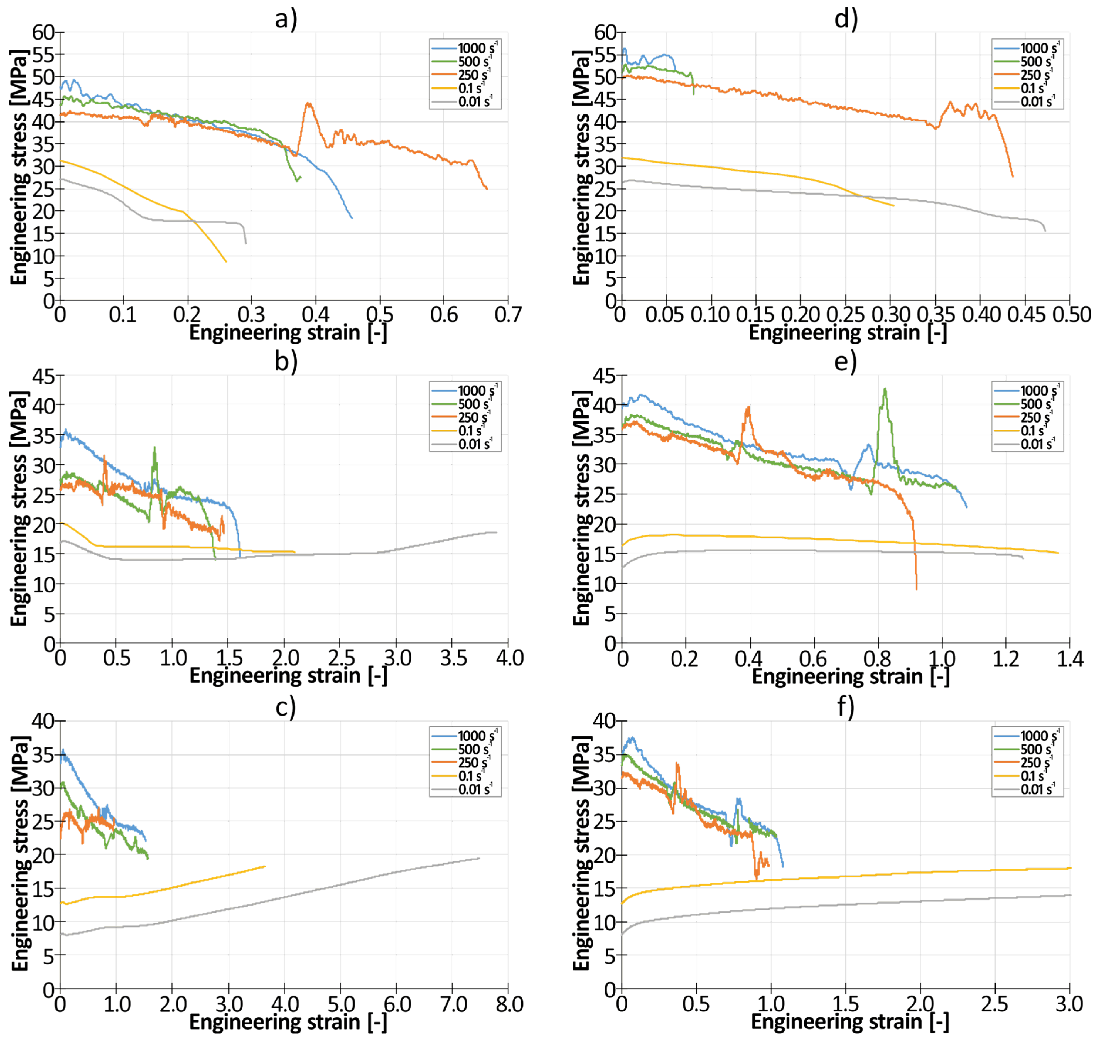
- In the case of materials’ mechanical properties, the significant, positive strain-rate sensitivity was observed. The intensity of this effect was strongly dependent on the amount of softening additive (PBAT or TPS). In the case of 50% of addition the ratio of dynamic yield strength to quasi-static yield strength was varying from 1.5 (for PLA50PBAT50) to 1.73 (for PLA50TPS50). As the amount of softening additive increases, the coefficient increases to 2.5 (for PLA15PBAT85) and 3.1 (for PLA15TPS85). Increase of the softening agent from 50% to 85% results in the significant increase of elongation at break from 0.025 (for PLA50PBAT50; ɛ̇=0.01) and 0.35 (for PLA50TPS50; ɛ̇=0.01) to about 3.7 (for PLA18PBAT80; ɛ̇=0.01) and 3.0 (for PLA15TPS85; ɛ̇=0.01).
- There is a clear influence of the amount of plasticizer in the case of PLA/PBAT energy-absorbing structures. The PLA15PBAT85 mixture have a deflection greater by approximately 7% (for T = -20°C), 14% (for T = 0°C), 25% (for T = 20°C), and 8% (for T = 40° C) relative to the PLA30PBAT70 mixture. For both mixtures, the maximum deflection increases as the material temperature increases.
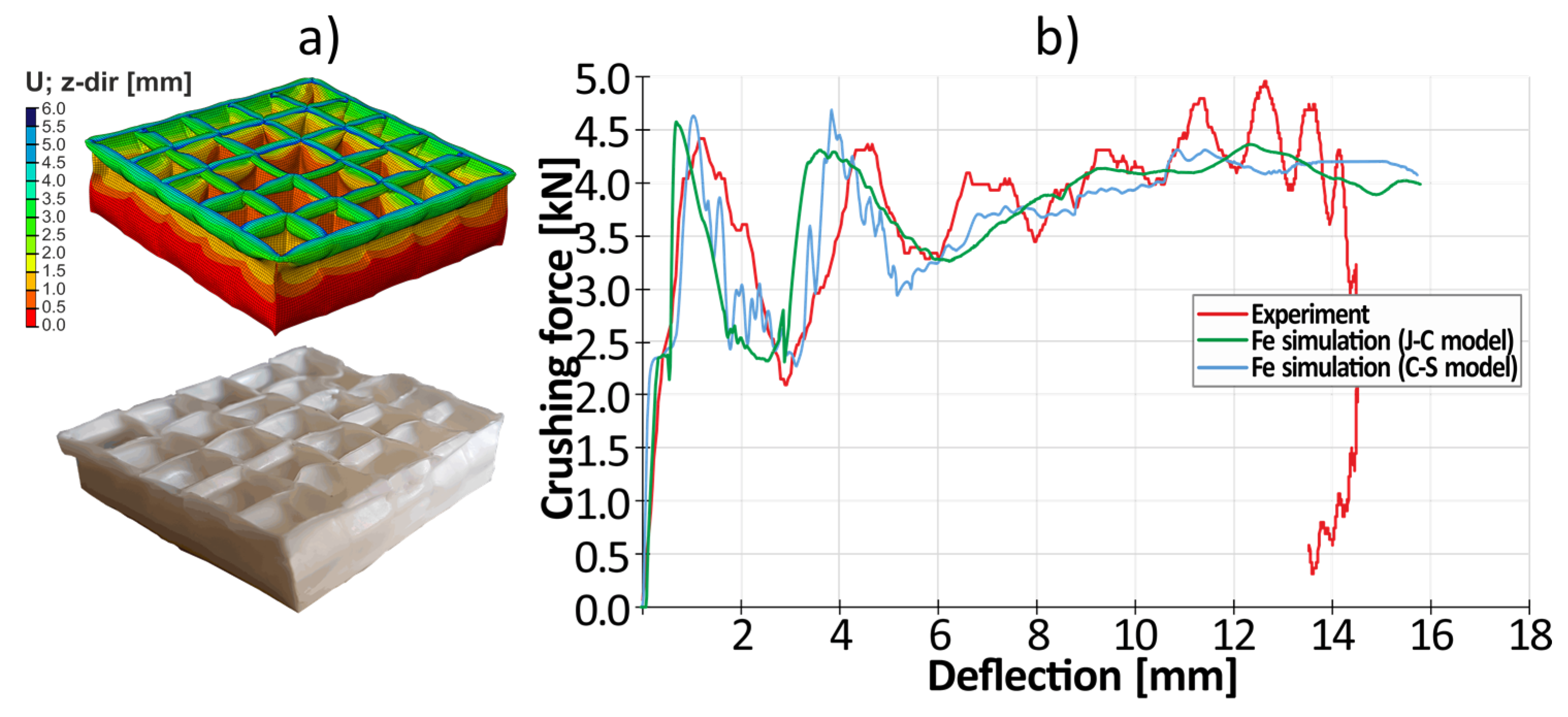
- Both Johnson-Cook and Cowper-Symonds material models are in good agreement with the experiment. This allows for further prediction of optimal geometric parameters of energy-absorbing structures on the basis of FE simulations.
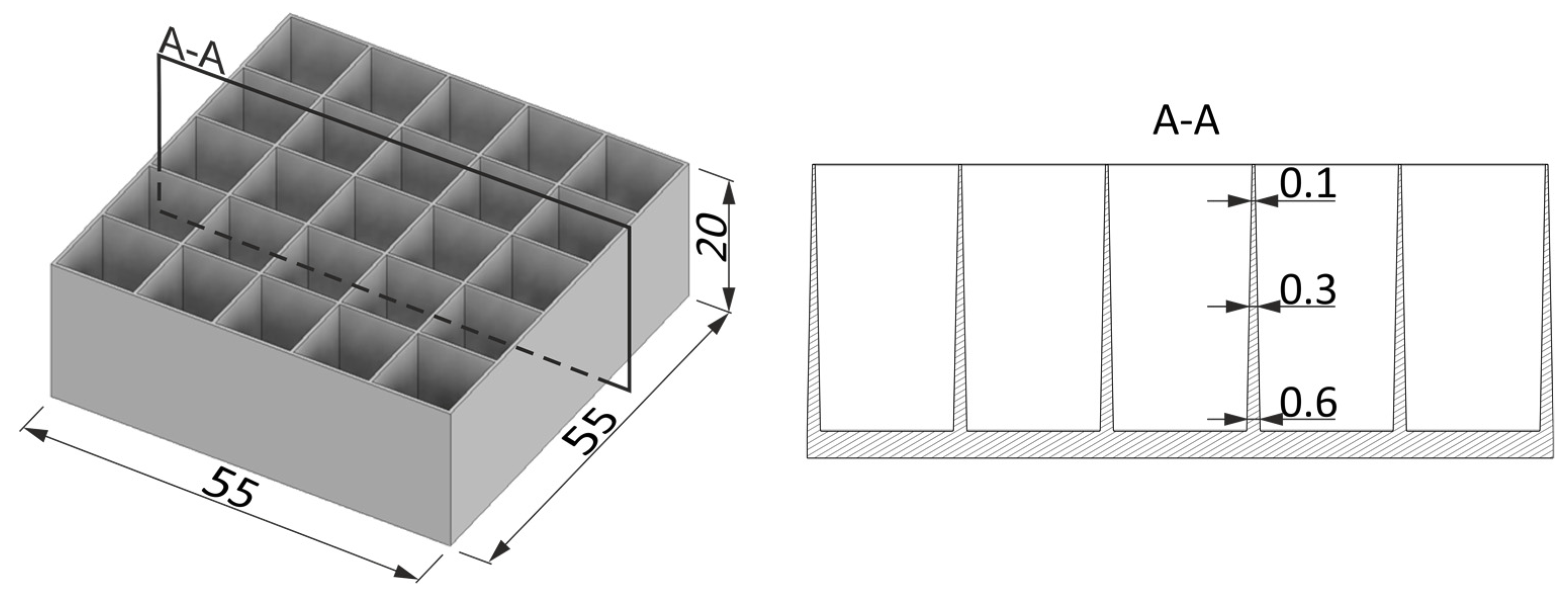
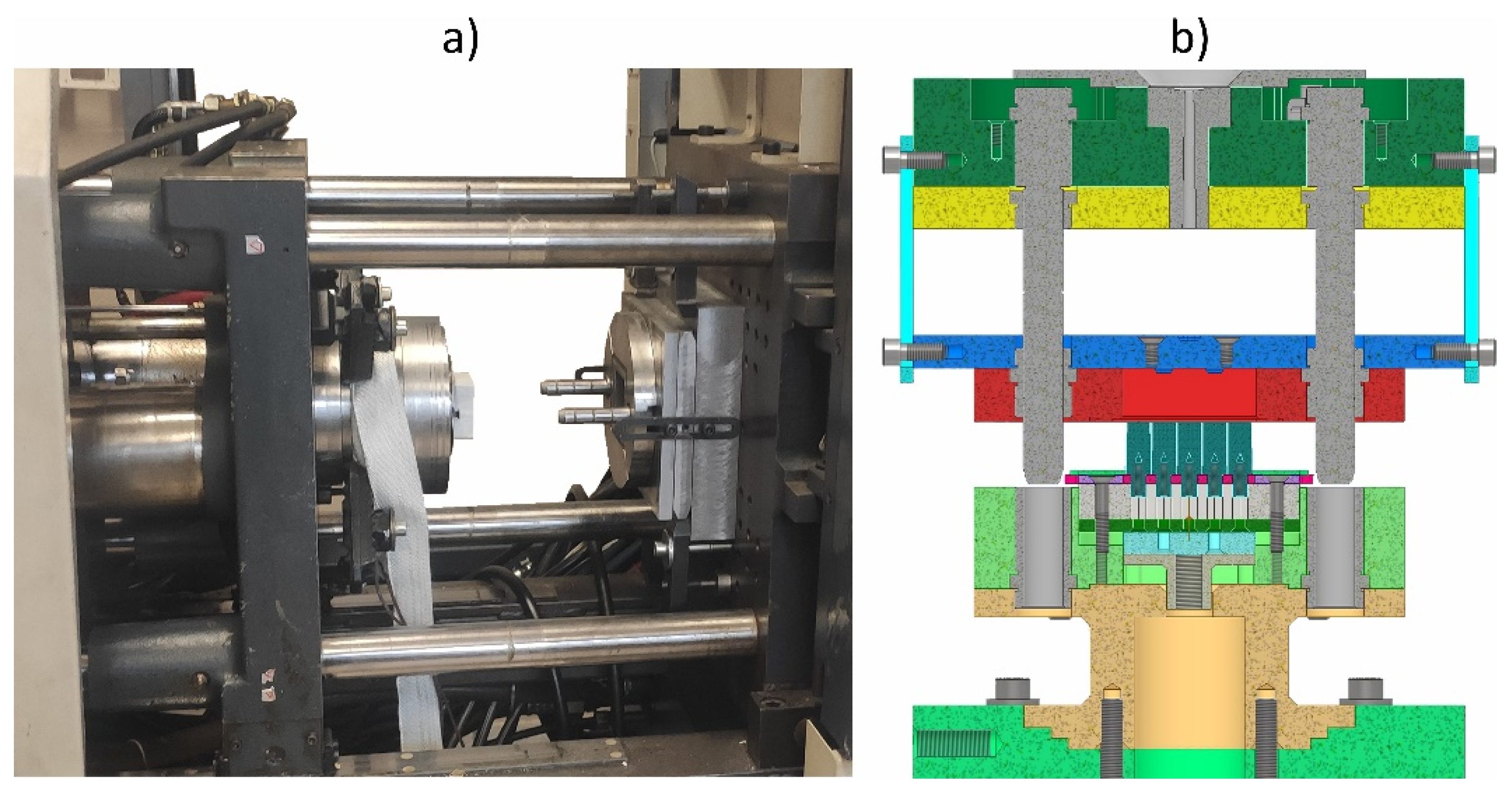
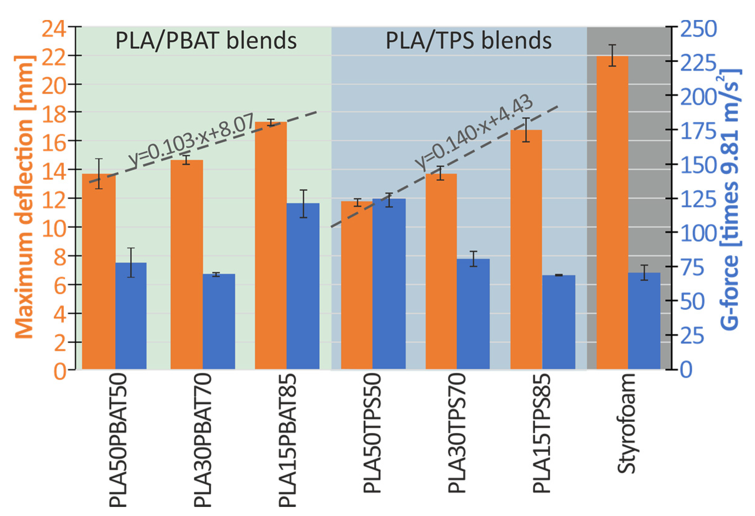
- In the case of both tested combination of materials, it can be concluded that the increase in the percentage of plasticizing additive (PBAT or TPS) in the blend results in decrease of the thickness of the gap that can be successfully filled during injection molding (Table 5). Increasing the plasticizing additive by 35% (from 50% to 85%) results in decrease of the thickness of the gap by about 32% in the case of PLA/PBAT blends (from 0.22 mm to 0.15 mm) and by about 26% in the case of PLA/TPS blends (from 0.23 mm to 0.17 mm).
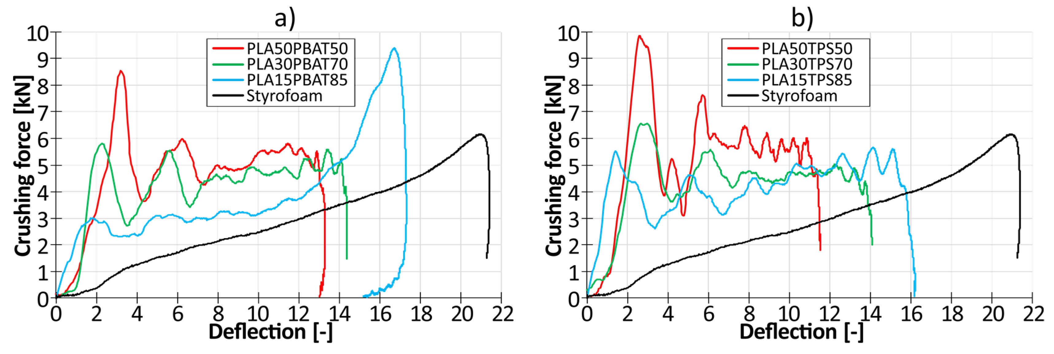
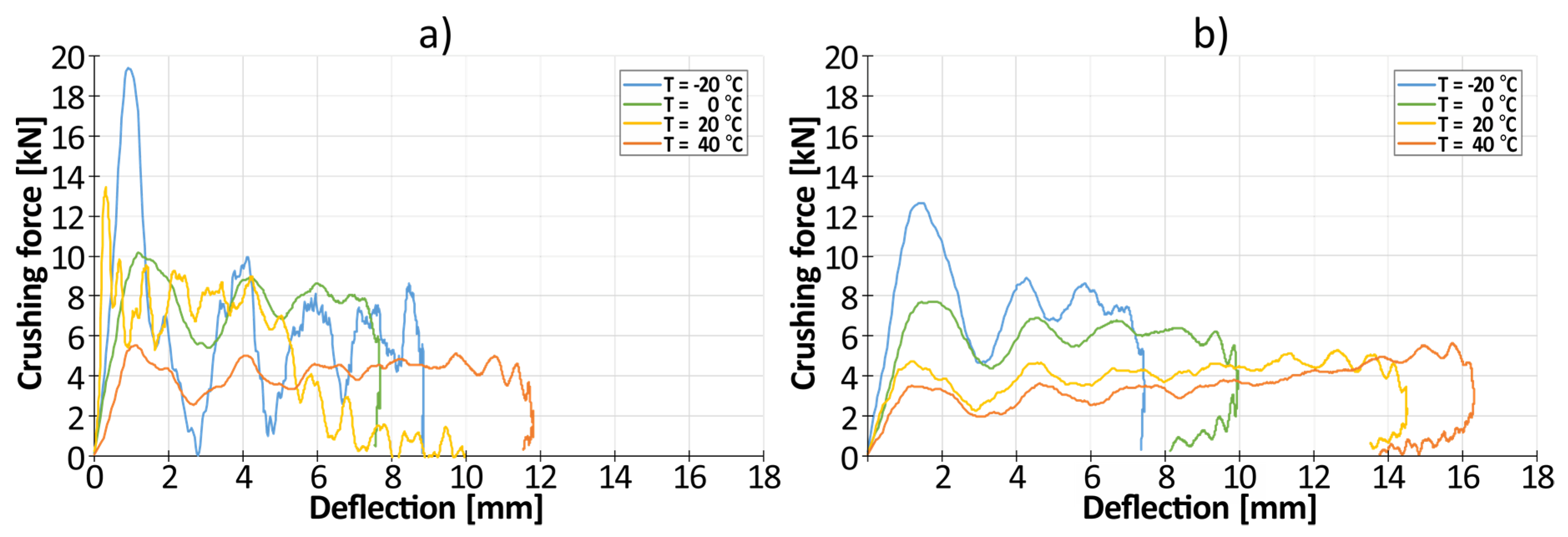
- As the content of plastic PBAT or TPS increases, the curve becomes flatter, i.e. the amplitude representing formation of the plastic folds becomes smaller, and the curves begin to resemble the styrofoam curve.
Author Contributions
Funding
Conflicts of Interest
References
- Ha, N.S.; Lu, G. A Review of Recent Research on Bio-Inspired Structures and Materials for Energy Absorption Applications. Compos. Part B Eng. 2020, 181, 107496. [CrossRef]
- Yang, S.; Bieliatynskyi, A.; Trachevskyi, V.; Shao, M.; Ta, M. Technology for Improving Modern Polymer Composite Materials. Mater. Sci. Pol. 2022, 40, 27–41. [CrossRef]
- Czech, K.; Oleksy, M.; Oliwa, R.; Domańska, A. Hybrid Polymer Composites with Enhanced Energy Absorption. Polimery/Polymers 2022, 67, 552–560. [CrossRef]
- Technical, O. Comparative Evaluation of Mechanical Properties of Short Aramid Fiber on Thermoplastic Polymers 1. 2023, 41, 161–176. [CrossRef]
- Akademia Baru, P.; Sofi, M.I.M. A Review on Energy Absorption of Multi Cell Thin Walled Structure. J. Adv. Rev. Sci. Res. ISSN 2015, 16, 2289–7887.
- Wang, X.; Wang, X.; Jian, K.; Xu, L.; Ju, A.; Guan, Z.; Ma, L. Mechanical Properties of Al Foams Subjected to Compression by a Cone-Shaped Indenter. ACS Omega 2021, 6, 28150–28161. [CrossRef]
- Endut, N.A.; Al Hazza, M.H.F.; Sidek, A.A.; Adesta, E.T.Y.; Ibrahim, N.A. Compressive Behaviour and Energy Absorption of Aluminium Foam Sandwich. IOP Conf. Ser. Mater. Sci. Eng. 2018, 290, 2–7. [CrossRef]
- Mahajan, A.; Singh, G.; Devgan, S. Additive Manufacturing of Metallic Biomaterials: A Concise Review. Arch. Civ. Mech. Eng. 2023, 23, 1–15. [CrossRef]
- Puga, H.; Carneiro, V.H.; Correira, P.; Vieira, V.; Barbosa, J.; Meireles, J. Mechanical Behavior of Honeycomb Lattices Manufactured by Investment Casting for Scaffolding Applications. Proc. Inst. Mech. Eng. Part L J. Mater. Des. Appl. 2016, 231, 73–81. [CrossRef]
- Rahman, O.; Koohbor, B. Optimization of Energy Absorption Performance of Polymer Honeycombs by Density Gradation. Compos. Part C Open Access 2020, 3, 100052. [CrossRef]
- Ingrole, A.; Aguirre, T.G.; Fuller, L.; Donahue, S.W. Bioinspired Energy Absorbing Material Designs Using Additive Manufacturing. J. Mech. Behav. Biomed. Mater. 2021, 119, 104518. [CrossRef]
- Doodi, R.; Gunji, B.M. Prediction and Experimental Validation Approach to Improve Performance of Novel Hybrid Bio-Inspired 3D Printed Lattice Structures Using Artificial Neural Networks. Sci. Rep. 2023, 13, 1–17. [CrossRef]
- Belingardi, G.; Montanini, R.; Avalle, M. Characterization of Polymeric Structural Foams under Compressive Impact Loading by Means of Energy-Absorption Diagram. Int. J. Impact Eng. 2001, 25, 455–472.
- Khatri, N.R.; Egan, P.F. Energy Absorption of 3D Printed ABS and TPU Multimaterial Honeycomb Structures. 3D Print. Addit. Manuf. 2023, 11, e840–e850. [CrossRef]
- Kumar, A.; Collini, L.; Ursini, C.; Jeng, J.Y. Energy Absorption and Stiffness of Thin and Thick-Walled Closed-Cell 3D-Printed Structures Fabricated from a Hyperelastic Soft Polymer. Materials (Basel). 2022, 15. [CrossRef]
- Namvar, N.; Zolfagharian, A.; Vakili-Tahami, F.; Bodaghi, M. Reversible Energy Absorption of Elasto-Plastic Auxetic, Hexagonal, and AuxHex Structures Fabricated by FDM 4D Printing. Smart Mater. Struct. 2022, 31. [CrossRef]
- Günaydın, K.; Rea, C.; Kazancı, Z. Energy Absorption Enhancement of Additively Manufactured Hexagonal and Re-Entrant (Auxetic) Lattice Structures by Using Multi-Material Reinforcements. Addit. Manuf. 2022, 59. [CrossRef]
- Kumar, S.; Ubaid, J.; Abishera, R.; Schiffer, A.; Deshpande, V.S. Tunable Energy Absorption Characteristics of Architected Honeycombs Enabled via Additive Manufacturing. ACS Appl. Mater. Interfaces 2019, 11, 42549–42560. [CrossRef]
- Mehrpouya, M.; Edelijn, T.; Ibrahim, M.; Mohebshahedin, A.; Gisario, A.; Barletta, M. Functional Behavior and Energy Absorption Characteristics of Additively Manufactured Smart Sandwich Structures. Adv. Eng. Mater. 2022. [CrossRef]
- Ha, N.S.; Pham, T.M.; Tran, T.T.; Hao, H.; Lu, G. Mechanical Properties and Energy Absorption of Bio-Inspired Hierarchical Circular Honeycomb. Compos. Part B Eng. 2022, 236, 109818. [CrossRef]
- Wu, C.; Nguyen-van, V.; Tran, P. Materials Science in Additive Manufacturing Energy Absorption and Recoverability of Moore. 2023, 2.
- Peixinho, N.; Carvalho, O.; Areias, C.; Pinto, P.; Silva, F. Compressive Properties and Energy Absorption of Metal-Polymer Hybrid Cellular Structures. Mater. Sci. Eng. A 2020, 794, 139921. [CrossRef]
- Diamantopoulou, M.; Roth, C.; Tancogne-Dejean, T.; Lauener, C.; Mohr, D. Ceramic/Polymer Microlattices: Increasing Specific Energy Absorption through Sandwich Construction. Extrem. Mech. Lett. 2022, 53, 101708. [CrossRef]
- Nian, Y.; Wan, S.; Zhou, P.; Wang, X.; Santiago, R.; Li, M. Energy Absorption Characteristics of Functionally Graded Polymer-Based Lattice Structures Filled Aluminum Tubes under Transverse Impact Loading. Mater. Des. 2021, 209. [CrossRef]
- Chen, J.; Li, E.; Liu, W.; Mao, Y.; Hou, S. Sustainable Composites with Ultrahigh Energy Absorption from Beverage Cans and Polyurethane Foam. Compos. Sci. Technol. 2023, 239, 110047. [CrossRef]
- Ragab, A.M.; Mahdi, E.; Oosterhuis, K.; Dean, A.; Cabibihan, J.J. Mechanical and Energy Absorption Properties of 3D-Printed Honeycomb Structures with Voronoi Tessellations. Front. Mech. Eng. 2023, 9, 1–15. [CrossRef]
- Shevchenko, V.; Balabanov, S.; Sychov, M.; Karimova, L. Prediction of Cellular Structure Mechanical Properties with the Geometry of Triply Periodic Minimal Surfaces (TPMS). ACS Omega 2023, 8, 26895–26905. [CrossRef]
- Gisario, A.; Desole, M.P.; Mehrpouya, M.; Barletta, M. Energy Absorbing 4D Printed Meta-Sandwich Structures: Load Cycles and Shape Recovery. Int. J. Adv. Manuf. Technol. 2023, 127, 1779–1795. [CrossRef]
- Bolan, M.; Dean, M.; Bardelcik, A. The Energy Absorption Behavior of 3D-Printed Polymeric Octet-Truss Lattice Structures of Varying Strut Length and Radius. Polymers (Basel). 2023, 15. [CrossRef]
- kumar Gurajala, N.; Sanjeev, L.; Teja, B.; Sai Kumar, T.; Eswara Manikanta, J. An Overview of Mechanical Properties of Biodegradable Polymers and Natural Fibre Materials. Mater. Today Proc. 2023. [CrossRef]
- Dicks, J.A.; Woolard, C. Biodegradable Polymeric Foams Based on Modified Castor Oil, Styrene, and Isobornyl Methacrylate. Polymers (Basel). 2021, 13. [CrossRef]
- Andena, L.; Caimmi, F.; Leonardi, L.; Nacucchi, M.; De Pascalis, F. Compression of Polystyrene and Polypropylene Foams for Energy Absorption Applications: A Combined Mechanical and Microstructural Study. J. Cell. Plast. 2019, 55, 49–72. [CrossRef]
- Murray, C.M.; Mao, M.; Park, J.; Howard, J.; Wereley, N.M. Visco-Elastic Honeycomb Structures with Increased Energy Absorption and Shape Recovery Performance Using Buckling Initiators. Polymers (Basel). 2023, 15. [CrossRef]
- Kawata, K.; Shioiri, J. Macro-and Micro-Mechanics of High Velocity Deformation and Fracture: IUTAM Symposium on MMMHVDF Tokyo, Japan, August 12–15, 1985; Springer Science & Business Media, 2012; ISBN 3642827675.
- Dmitruk, A.; Ludwiczak, J.; Skwarski, M.; Makuła, P.; Kaczyński, P. Influence of PBS, PBAT and TPS Content on Tensile and Processing Properties of PLA-Based Polymeric Blends at Different Temperatures. J. Mater. Sci. 2023, 58, 1991–2004. [CrossRef]
- Emsley, B.; Farmer, J.; Sherratt, P.; Goodall, P.; Jackson, T.; West, A. An Overview of the Test Methodology Used in Current Cycling Helmet Standards and Literature. Int. J. Impact Eng. 2024, 188, 104928. [CrossRef]



| Material | Ultimate tensile strength [MPa] | Maximum elongation [%] |
|---|---|---|
| PLA | 60-70 | 7-8 |
| PBAT | 14-20 | 570-740 |
| TPS | 12-15 | 560-580 |
| Blend | PLA/PBAT blend | PLA/TPS blend |
|---|---|---|
| Mold temperature [°C] | 50 | 50 |
| Injection molding screw temperature [°C] | 205-200-190-180 | 210-205-195-185 |
| Injection pressure [bar] | 900 | 950 |
| Injection velocity [m/s] | 120 | 120 |
| Injection time [s] | 8 | 8 |
| Clamping pressure [bar] | 130 | 130 |
| Cooling time before opening the mold [s] | 40 | 40 |
| Injected volume [cm3] | 20 | 20 |
| Material | Young’s modulus[GPa] | Poisson’s ratio[-] | Density[g/mm3] |
|---|---|---|---|
| PLA15TPS85 | 0.24 | 0.22 | 0.00114 |
Disclaimer/Publisher’s Note: The statements, opinions and data contained in all publications are solely those of the individual author(s) and contributor(s) and not of MDPI and/or the editor(s). MDPI and/or the editor(s) disclaim responsibility for any injury to people or property resulting from any ideas, methods, instructions or products referred to in the content. |
© 2024 by the authors. Licensee MDPI, Basel, Switzerland. This article is an open access article distributed under the terms and conditions of the Creative Commons Attribution (CC BY) license (http://creativecommons.org/licenses/by/4.0/).


