1. Introduction
The development of the technology and manufacturing ability has enabled us to cross the gap of ocean and explore the unknown world. However, the complex phenomenon and mechanism of the interaction between navigators and water are ubiquitous in ocean engineering and are of great significance to study these problems for structural safety, transportation efficiency and target deployment [
1,
2,
3,
4,
5]. In 1929, von Karman, as the pioneer to study the seaplane water entry impact problem, conducted theoretical and experimental research on the interaction between navigators and water[
6]. Since then, many researchers have carried out deep study on the mechanism of the interaction by theory, experiment and numerical simulation with the development of technology and a large number of results are obtained, which improved the design and manufacture of ships, submarines, seaplanes and so on[
7,
8,
9,
10,
11,
12,
13,
14].
According to the manner of structures crossing the water interface, the interactions between the navigators and water include water entry, in-water motion, and water exit processes. Among them, the study of water entry and water exit stages are more complicated due to the multi-phase and cross-media nature. The water entry scenarios, which widely present in ocean engineering[
15] and natural phenomena[
16], have been attracted much attention with extensive researches. In the early stage of water entry study, flow visualization by high-speed camera[
17,
18,
19] was applied to capture the details of flow. Subsequently, many experimental [
20,
21,
22]and numerical studies[
23,
24,
25] were also carried out to analyze the pressure distribution, impact force, shape design and cavity. However, compared to the water entry problem, much less works have been conducted for the water exit problem due to the fact that the physical processes and nonlinear properties involved in the water exit problem are much more complex than those of the water entry stage. Although water-exit and water-entry appear to be the opposite physical processes, the water exit problem cannot be simply treated as the reversal of the water entry problem. For example, Oliver gave specific explanations[
26]in the perspective of the stability of the theoretical solution according to the obtained implicit dispersion relation they obtained by matching the water entry and water exit solutions. They founded that the leading-order water exit problem is linearly stable only when the turnover curve is increasing, which implies that the water exit problem regarded as the reversal of the water entry problem is linearly unstable. Besides Ni et al. [
27]also founded that contrary to the gradual increase of fluid load and fluid-solid coupling force during water entry, water exit is the process with reducing wetted area, gradual solid-liquid separation, and smaller fluid load. Furthermore, it is more challenging to apply Wagner’s theory[
28], which utilizes a linear free-variable interface condition with a correction for the water line.
Although the water exit problem is very complex and involved with multiphase flow, phase change, turbulence, cavitation or super cavitation, it has a wide range of applications like drag reduction[
29], underwater navigation[
30], unmanned aerial-underwater vehicles[
31,
32], and so on, which has been attracted great attention in many fields[
1,
29,
33,
34,
35]. The water exit process occupies an extremely important stage in the whole cycle of these objects’ motion, and is related to some important parameters such as speed and attitude after water exit, which directly affects the stability and striking accuracy of the vehicles and determines the success or failure of the mission[
36,
37]. In this work, the studies on the water exit problems conducted by researches since von Karman are summarized including theoretical research, numerical simulation and experimental development. The current developments as well as the difficulties in research of water exit problems are summarized and analyzed. Future possible research directions of the water exit problem are also given.
This paper is organized as follows.
Section 2 presents two kinds of theories in details to describe the water exit process.
Section 3 summarizes the water exit experiments conducted by researches.
Section 4 gives several numerical simulation methods for solving the water exit process. Finally,
Section 5 concludes the current development of water exit problem and provides several outlooks on future research of water exit problem.
2. Theoretical Research
Due to the complex nonlinear property, the theoretical researches on water exit problem are insufficient. Although many studies have been conducted, like line source distributions and slender-body theory[
38,
39,
40], linear theory[
41,
42], and added-mass theory[
43,
44,
45], these theories face many limitations on the practical applications and the prediction accuracy is unsatisfactory. This section presents two theoretical water exit models, i.e. the improved Von Karman model and the linearized water exit model. The improved Von Karman model originates from the von Karman model[
6], which has been successfully adopted to calculate the hydrodynamic forces on the seaplane landing on water. The linearized water exit model is mainly used to calculate the hydrodynamic forces on the object during the water exit of a rigid body with constant acceleration.
2.1. Improved von Karman Model
The von Karman model, firstly proposed to solve the hydrodynamics forces on seaplane landing and agreeing well with the experimental data[
6], cannot be applied to the water exit process directly due to the discontinuity of the physical quantities at the contact points in the water entry-exit process. To address this issue, Tassin[
46] proposed an improved von Karman model, which is achieved by approximating the derivative of the object’s potential function by the acceleration potential function and its Taylor expansion for water exit problem.
To maintain the continuity of the contact point coordinates in the water entry-exit process, the reference level is modified. Furthermore, in order to guarantee pressure continuity in the water entry-exit process, the derivative of the object potential function is approximated by the acceleration potential function and its Taylor expansion. Thus, the force in the vertical direction of the object is obtained as follows.
where
,
represents the shape function of the object,
the contact point position,
denotes a principal value integral and can be set as a constant,
is the stream function on the body surface.
The water entry-exit process of a two-dimensional rigid wedge was simulated by Piro in Ref [
47]. In the model, the initial velocity is set as
, angle of attack
, acceleration
. The displacement equation is
. When
, the velocity
V decreases to
, where
is set as the dimensionless time reference variant with the dimensionless time
. Therefore, when
, the object is in the water entry stage, thus the theoretical force can be obtained by Wagner’s theory[
28,
48]. When
, the object is in the water exit stage, and the theoretical force is solved by the linearized model. Using
as the dimensionless force reference variant, the dimensionless force is
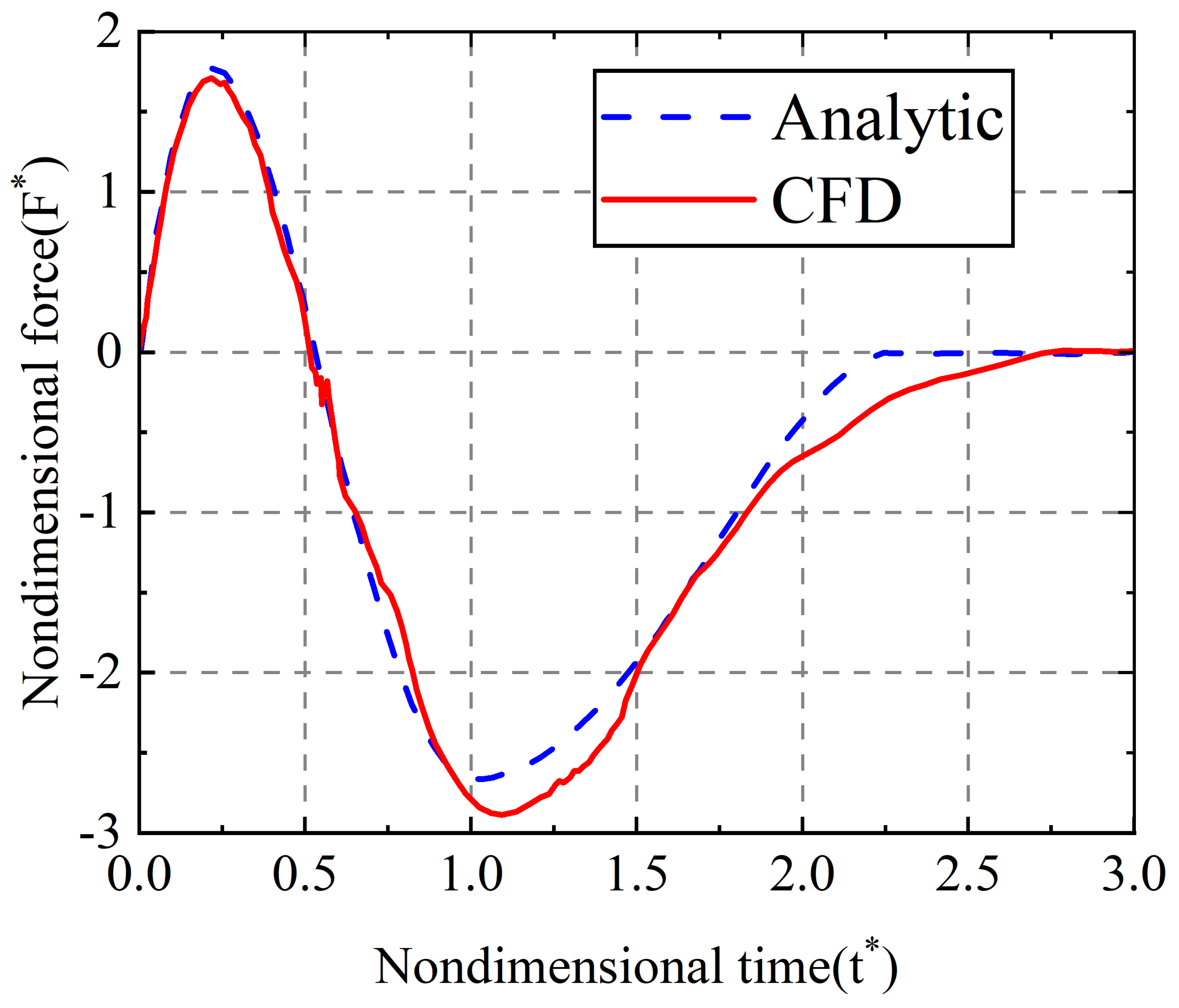
. The force evolution during the water entry and exit of a wedge obtained by the model is shown in
Figure 1:
Adel Shams[
49] also described the water exit process of the wedge with the improved von Karman model and obtained pressure field data from water entry to water exit by the PIV (particle image velocimetry) technology(see in Ref.[
49]), which agreed well with each other.
2.2. Linearized Water Exit Model
The linearized water exit model was proposed in Ref[
50], which is only applicable to symmetric rigid bodies initially located at the free liquid surface with uniform acceleration water exit vertically. Based on the assumption that the velocity at the contact point is proportional to that of the local fluid and by linearizing the pressure, this model was developed without taking into account the shape of the object, while good agreement with the numerical simulation is achieved[
50]. In order to solve water exit problem with changing acceleration, the model was further modified by taking into account the object shape and some nonlinear terms in Bernoulli’s equation[
46]. The research improved the theoretical prediction accuracy and was applied to investigate the steady-state problem of ellipsoidal bodies moving along the water surface in a shallow submerged state.
The linearized water exit model can be linearized according to the following reasons.
(1) The time range of the water exit phase is , in which the vertical displacement of the object is of order . The order of vertical displacement is much smaller than the reference dimension, i.e, , which is far less than 1. For the reference dimension , denotes the reference dimension for length and object acceleration a as the reference dimension for flow acceleration.
(2) Fluid velocity is of order;
(3) The viscous term in the NS equation can be neglected because , and in the early stage of water exit ( at 20°C). The convective term can be ignored because . These two approximations are valid in the main flow region and can be ignored. However, the approximation is no longer satisfied in the flow region close to the object where submergence depth, fluid viscosity, and contact line motion properties have significant influence.
(4) When the acceleration a is large, . Thus the gravity can be neglected.
(5) The extension velocity of the contact point is proportional to the corresponding local fluid velocity, that is .
At the moment
t , the force
acting on the object can be expressed,
From the boundary conditions, we can get,
where
denotes the contact point and
denotes the acceleration of objects.
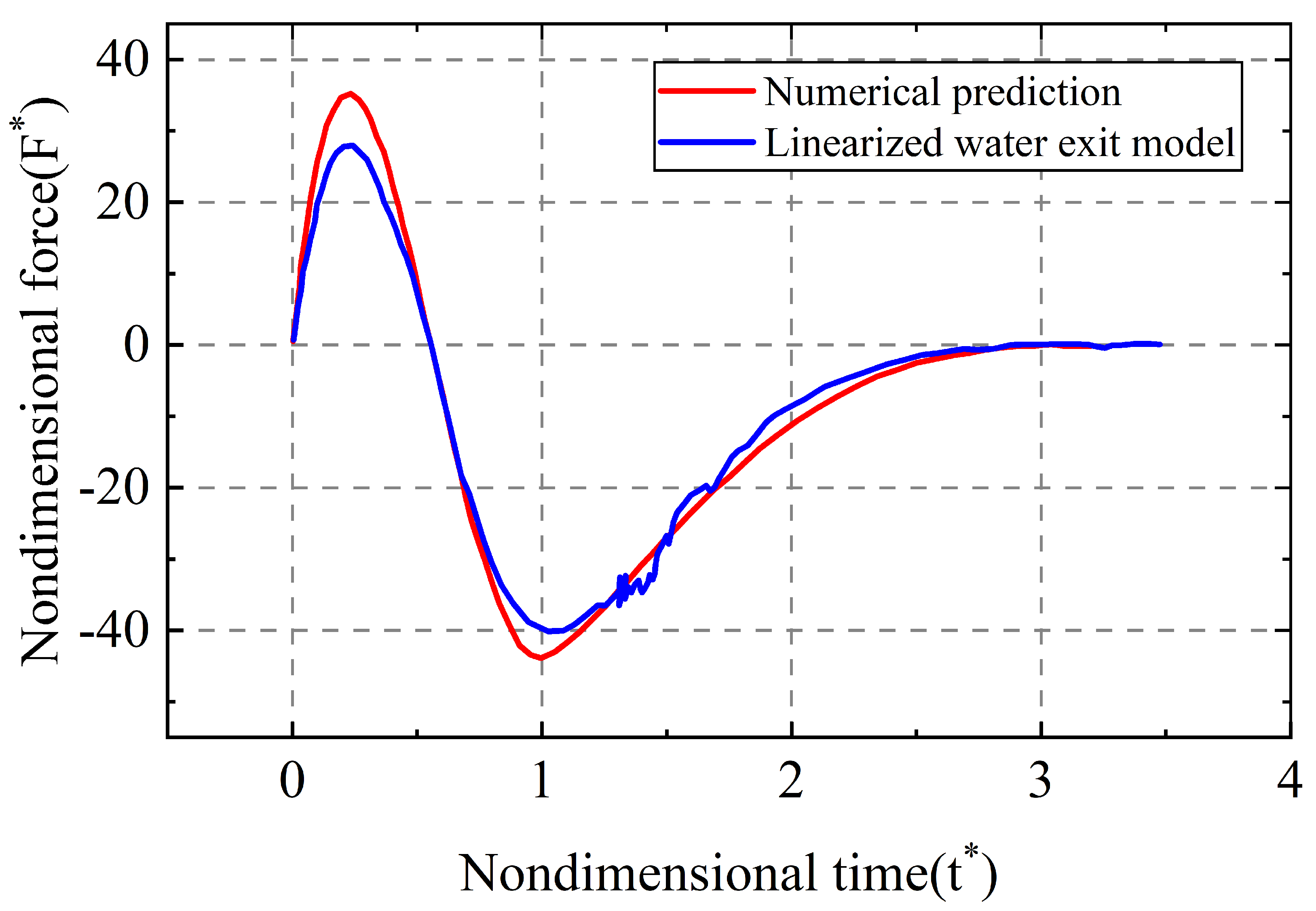
The numerical calculations performed by Piro et al.[
46,
47]. were compared respectively. The wedge rigid body model is described in
Section 2.1, and the numerical and theoretical solutions are shown in
Figure 2.
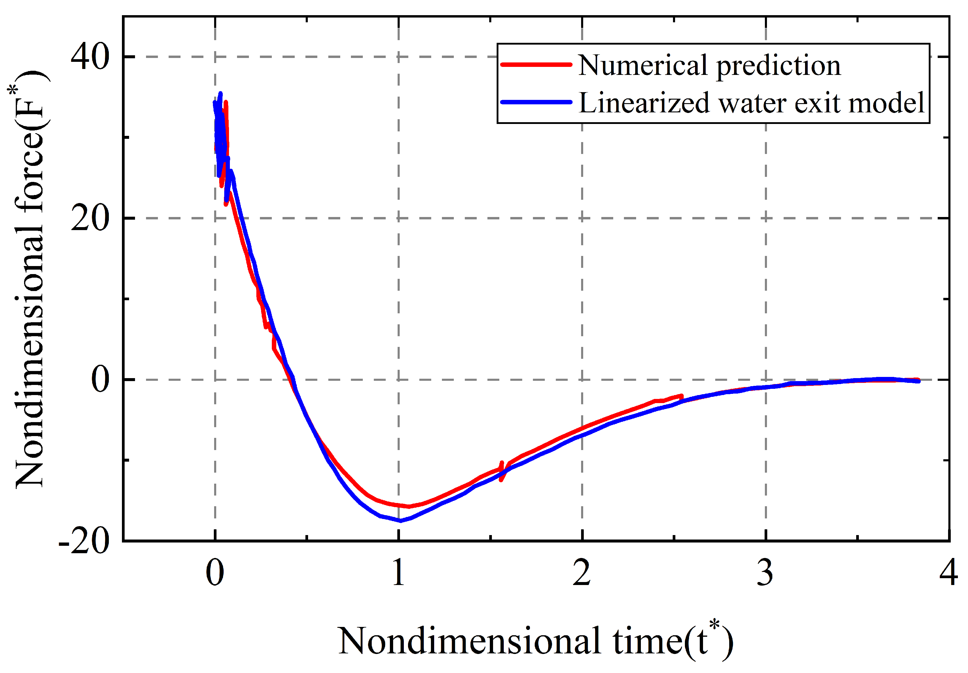
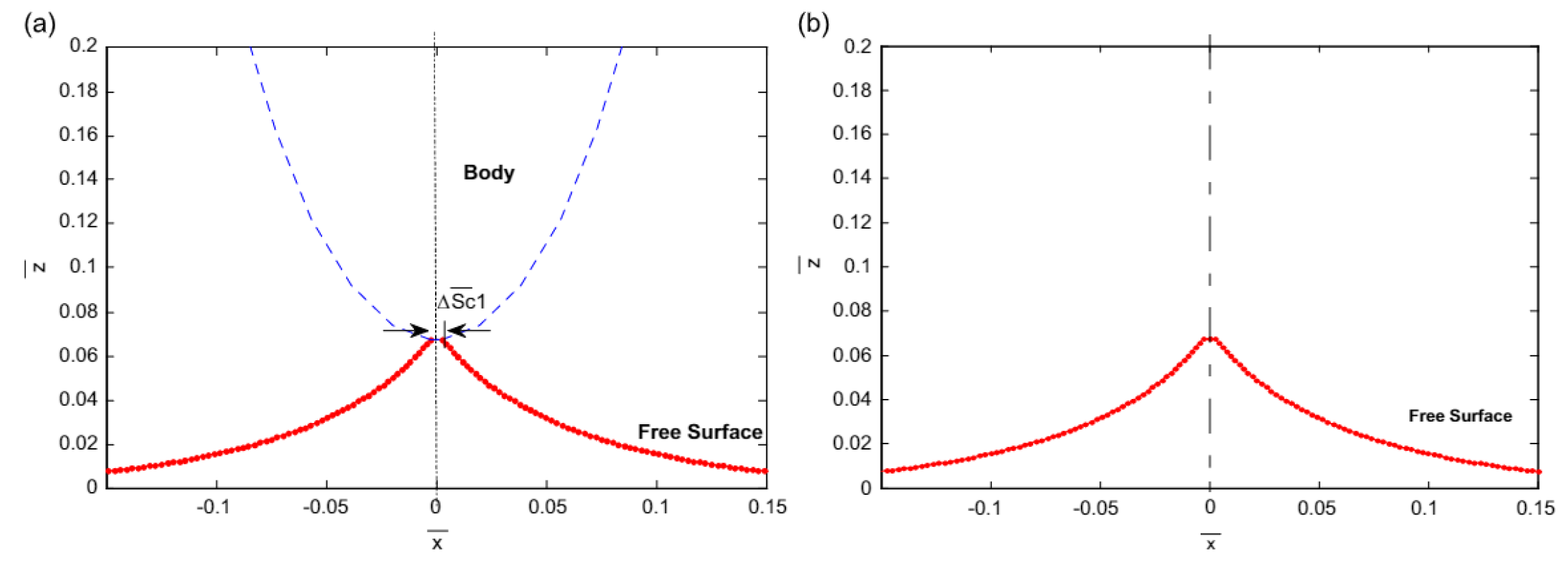
The water entry-exit problem for a parabolic shape object was simulated by Piro[
46]. In the model, the contour function is set as
(
),
,
. The numerical and theoretical solutions are shown in
Figure 3.
From
Figure 2 and
Figure 3, it can be observed that the numerical solution of the water exit stage agrees well with the theoretical solution of the linearized model.
2.3. Discussion
Although the improved von Karman model and the linearized water exit model agree well with the numerical results, they are both derived on the basis of several assumptions mentioned above. There remain some limitations in the following aspects. Firstly, the object models are two-dimensional, and both are rigid bodies. Secondly, the water exit process mentioned is not a pure water exit process, which is one stage of the whole water entry-exit process and can be classified into the semi-submerged water exit process at low speed. Thirdly, the force load of the object in the vertical direction during the water exit process was deduced in the improved von Karman model, in which it can be seen that the force load is significantly dependent on the position of the contact point
. In the stage of water entry process, Wagner theory is well applied to evaluate
. However, the water separation in the water exit process will lead to bias in the calculation despite some modification. Fourthly, as for the linearized water exit model, the assumptions (1)-(5) will not be valid as the penetration depth or velocity increases and the acceleration decreases. The effects of surface tension and viscosity near the water contact area on the surface pressure of the object should be taken into account under those circumstance. Lastly, the nonlinear terms are ignored in both models when calculating the pressure, which is problematic when calculating the impacting force. The linear Bernoulli equation is used in the improved von Karman model while the linear Euler equation is applied in the linearized water exit model. With the increase of structure speed and size , the impact of the non-linear term on the pressure can’t be ignored. Tassin et al. also inferred that the non-linear term would have a remarkable impact on the pressure in the wake region during the water exit process[
46].
Although there still exist some limitations for the improved von Karman model and linearized water exit model, their exploration in water exit problem indeed provided us with valuable references. On the basis of these two models, there are some aspects worth optimizing and deeply researching as follows.
(1) From the derivation of the theoretical model, it can be seen that the calculation of the pressure term is the key to solve the hydrodynamic force load. In these two theoretical models, the pressure term is calculated by directly omitting the non-linear term, so we can further explore the linearization of the non-linear term instead of omitting it to solve the pressure term.
(2) Expand the research object from two-dimensional rigid body to three-dimensional to make it closer to the actual situation. The current theoretical models is mainly aimed to solve the overall force load of the object in the water exit process. In the actual scenario, most of the navigation bodies are made of shells, such as ships, submarines, missiles, etc. In the further study, the influence of hydrodynamic load on the structural deformation of local navigation bodies can be analyzed in combination with shell structure theory and elastic body theory.
(3) Expand the research process. The water exit process mentioned is one stage of the whole water entry-exit process. In the further research, the pure fully-submerged water exit process at different depth is worthy of further in-depth studies, and with the increase of the exiting speed, there will be more complex phenomena emerging like multiphase flow, cavitation, etc. The occurrence of these phenomena and their impact on the navigation bodies are worth theoretical analysis.
3. Experiment Development
Experiments are the most direct way to obtain first-hand data. However, experiments on water exit processes face many difficulties in practice. The first difficulty lies in the method powering exit velocity underwater. Currently, there are two main approaches, i.e. the active and the forced water exits. In the active water exit, automatic water exit of the neutral object due to its own buoyancy[
51,
52,
53,
54,
55,
56], air pump to eject objects[
46,
57,
58,
59,
60,
61,
62,
63], etc, are normally included, which has the disadvantages of low exiting velocity and the air will interfere to the water exit process. In the forced water exit, object water exit driven by thin rope [
46,
52,
64] or long rod[
65], L-shaped rod[
65], and lifting platform[
66,
67,
68] are included, in which the components tied to the objects will cause interference to the fluid field. The second difficulty is the way obtaining experimental images. In the underwater stage, bubbles and fine flow structures bring challenge to capture the fluid field detailly when the objects move at low speed. If the structures exit at a high speed, the fluid fields around the structure are evolving violently blocking the light of the object image and stop us taking the picture. The third difficulty is to monitor the experimental data. The velocity displacement and other motion parameters of the structure can be obtained by the high-speed camera directly while the fluid field, especially the pressure field and velocity field around the object, are not easy to observe. There are mainly two ways widely-used, namely the PIV technology [
49,
51] and the pressure sensors attached on the object[
51]. Nevertheless, the local impact force loaded on the moving object and the internal structural stress changes are still unavailable by experiments. Lastly, the cost of water exit experiments is far higher than that of the water entry process, especially for the design of underwater devices.
Despite the difficulties in conducting water exit experiments, many scholars have done a lot of pioneering research on the water exit problem and obtained plenty of valuable results, which greatly contributed to the verification and development of water exit theory and the designing development of underwater navigation bodies. This section reviewed the forced and active water exit experiments conducted by scholars. Furthermore, as cavitation occurs in many experiments under certain conditions, the corresponding research is also summarized in the end.
3.1. Forced Water Exit
In 1983, Greenhow et al.[
52] conducted a series of experiments on the water exit process of a neutrally buoyant cylinder initially located at the bottom of a water tank by applying a constant force equal to its gravity through a thin rope, in which captured the liquid surface lifting and the liquid surface-breaking phenomenon were captured. It was found that the liquid surface-breaking could be caused by the interaction of the eddy dislodged from the cylinder with the free liquid surface (the liquid surface deformation due to the rise of the sphere can be found by Lighthill [
69]and the forces during the rise of the sphere can refer to the work by Faltinsen[
70]. The causes of liquid surface-breaking have also been studied by Peregrine [
71,
72] and Broeck [
73] successively. According to Peregrine’s study, a force limit exists for vorticity, otherwise the flow is unstable. Vanden’s study further shows that the force on the eddy in Peregrine’s corollary is always divergent and will eventually exceed the force limit, leading to the inevitable breakup of the liquid surface.
Miao, in his doctoral thesis[
64], conducted water exit experiments on horizontal cylinders with 0.512m/s and 0.764m/s uniform velocity and obtained the impact coefficient variation curve with time. He stated that the water exit fluid at the upper end of the cylinder makes the additional mass change more smoothly. Besides, when the exit displacement is up to the radius length, the fluid below the cylinder is rapidly filled with a large number of bubbles, which will either create cavities or lead to spontaneous breaking of the free liquid surface. He also found that surface tension and cavitation may have an important effect in reducing the additional mass force.
Although it is operationally easy to conduct experiments by tying a thin rope to the front section of the objects to push them exit, this will inevitably disturb the free liquid surface before water exit. In order to avoid the disturbance, Wu et al. [
65,
74] used an L-shaped restraint mechanism in the experimental setup , as shown in
Figure 4 and
Figure 5. The motion control of the object is achieved by electromagnetic force.
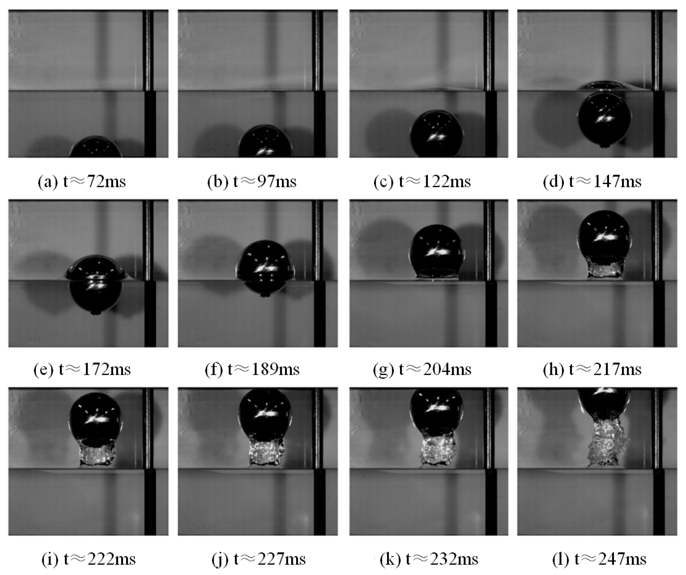
Using this experimental setup, Wu[
65] conducted experiments on fully submerged and partially submerged spheres forced constantly to water exit (0.2-0.7 m/s) (
Figure 6), as well as the free water exit experiments of a light sphere (density 100 kg/m3).The effects of different velocities, different submersion depths, and Froude number on the water exit process were investigated and the velocity, displacement, acceleration, and drag coefficient curves with time [
65] were also obtained. Furthermore, experiments were conducted on the free water exit and water re-entry process of hollow light aluminum ellipsoid [
74]. The effects of relative density (ratio of mass to actual volume) and immersion depth on the water exit process were investigated and thus the velocity variation curves were obtained, which were in good agreement with the BEM numerical simulation results.
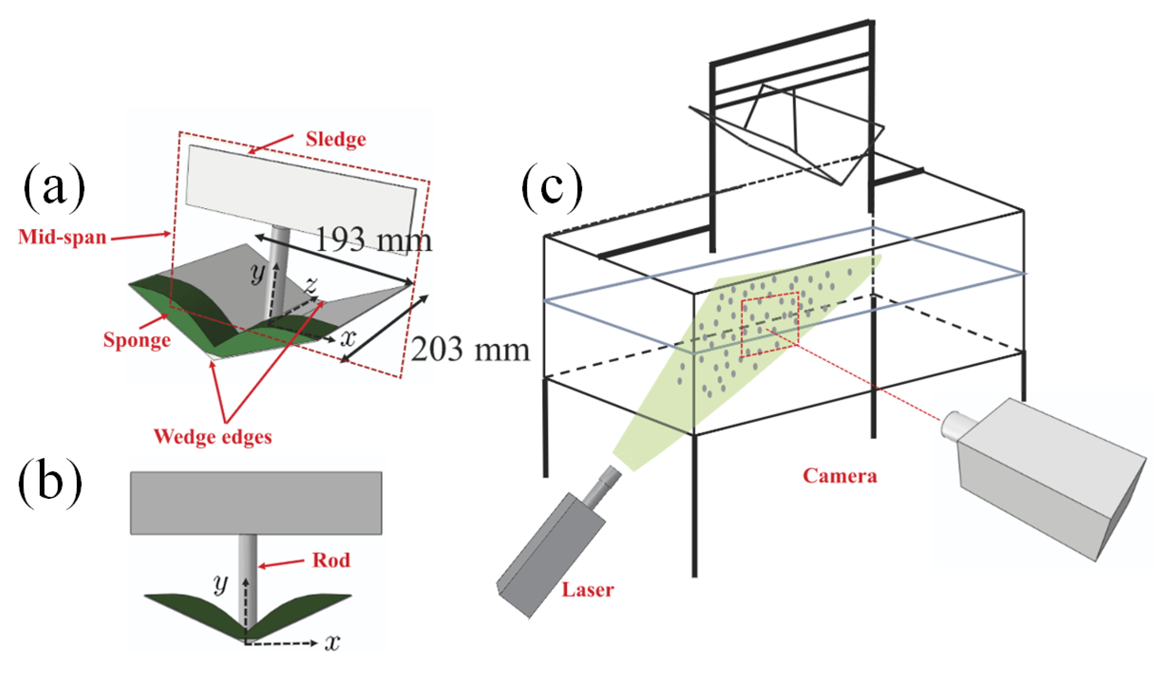
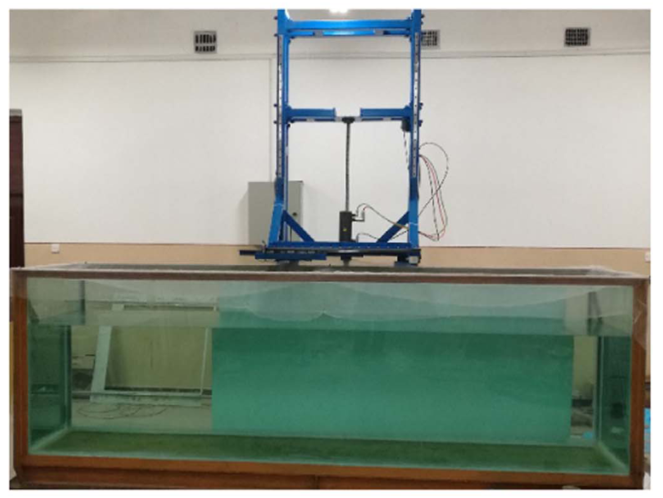
Previous water exit experiments mainly focused on the physical parameters of the object itself, while the data of the flow field was rarely analyzed as it was very difficult to acquire. To address this issue, Adel Shams [
49] adopted the PIV technology to estimate the fluid velocity field. Experiments were conducted on a specially designed lift tower apparatus (shown in
Figure 7) for the whole process of the wedge from water entry to water exit. After obtaining the velocity field, the fluid pressure field was deduced according to the incompressible NS equation. The experimental results show that, different from the positive pressure field in water entry process (with respect to the atmospheric pressure), the negative pressure field occurs in water exit process [
49].
In 2020, Tassin et al. [
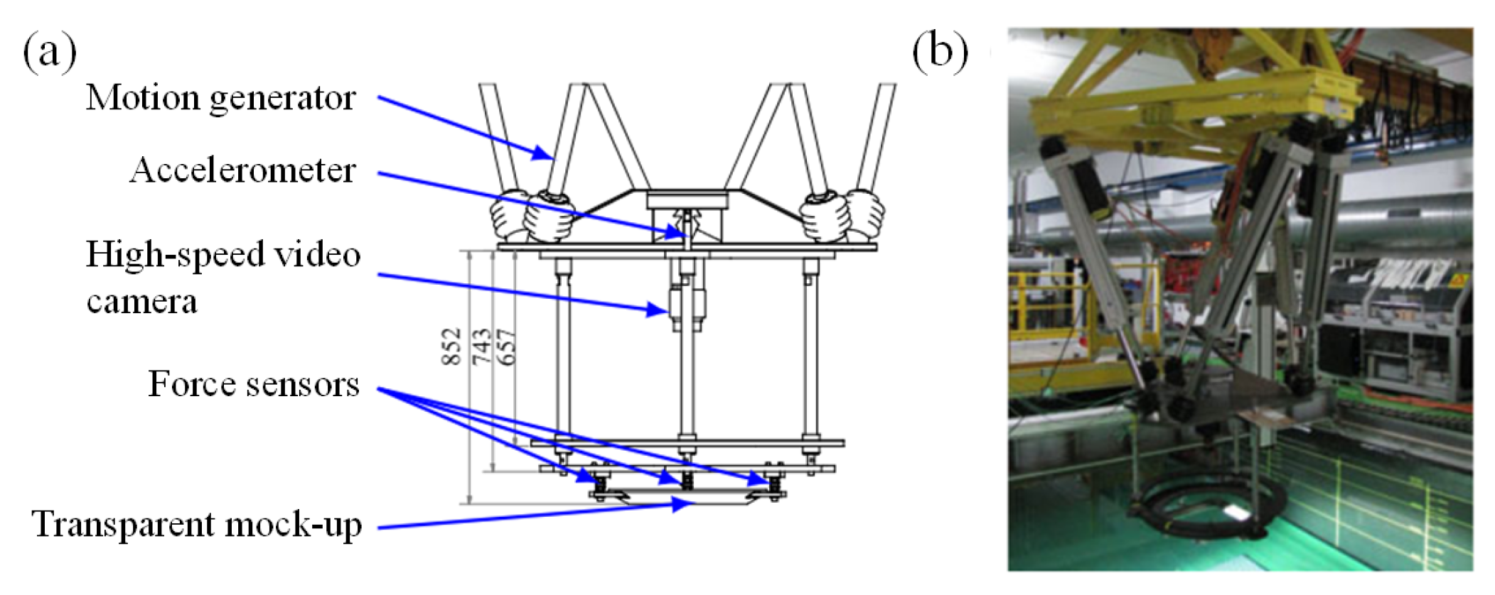
75]conducted experiments with symmetrical bodies (discs, cones, and spheres) in order to study the evolution of the wetted area and the forces on the object during water exit (
) and water entry-exit. Tassin redesigned the experimental setup using a fully transparent experimental model and LED edge illumination device (
Figure 8), firstly proposed in [
76], in which the size of the wetted area and the forces on the object can be clearly captured. The following conclusions are drawn according to the experimental results.
(1) The shape of the object has no significant effect on the evolution of the wetted area during water exit.
(2) Experiments with different initial submerging depths and different number show that surface tension and viscosity have no significant effect during water exit.
(3) The evolution of the wetted region in the water exit stage of the water entry-exit process is very similar to that of the pure water exit process.
(4) The theoretical solution obtained from the improved von Karman model does not agree well with the experimental results of water exit. When gravity is neglected, the theoretical solution obtained from the linearized water exit model (at ) agrees well with the experimental in the early stages of water exit. Still, the theoretical values in the submerged region (due to the effect of gravity) are slightly higher than the experimental values.
In the water exit process with low speed, cavitation is not easy to be produced by objects . Besides, carrying out high-speed water exit experiments is also not an easy task. To overcome this dilemma, Ren et al[
77]conducted a large number of the hemispherical-headed elongated body (
,
) water exit experiments with uniform velocity (0-3.36 m/s) based on a novel depressurized underwater navigational experimental setup by adjusting the ambient atmospheric pressure to 5000Pa-10000Pa ). The effects of the
number and the cavitation number
on the generation, development, and collapse of natural bubbles during the water exit of slender bodies were analyzed, and the four stages of vacuole water exit collapse were observed and summarized: top contact of bubbles, propulsive collapse, simultaneous collapse, and jet rebound. The experimental results show that the Fr number has an effect mainly on the shape of the bubble, which is called "bubble cavitation" when Fr is low and "sheet cavitation" when
is high, while the cavitation number
mainly affects the size of the bubbles.
3.2. Active Water Exit
Compared with forced water exit experiments, the main difficulties in conducting active water exit experiments lies in how to give the object sufficient initial velocity of water exit without disturbing the fluid field. In recent years, scholars have done a lot of pioneering work on this.
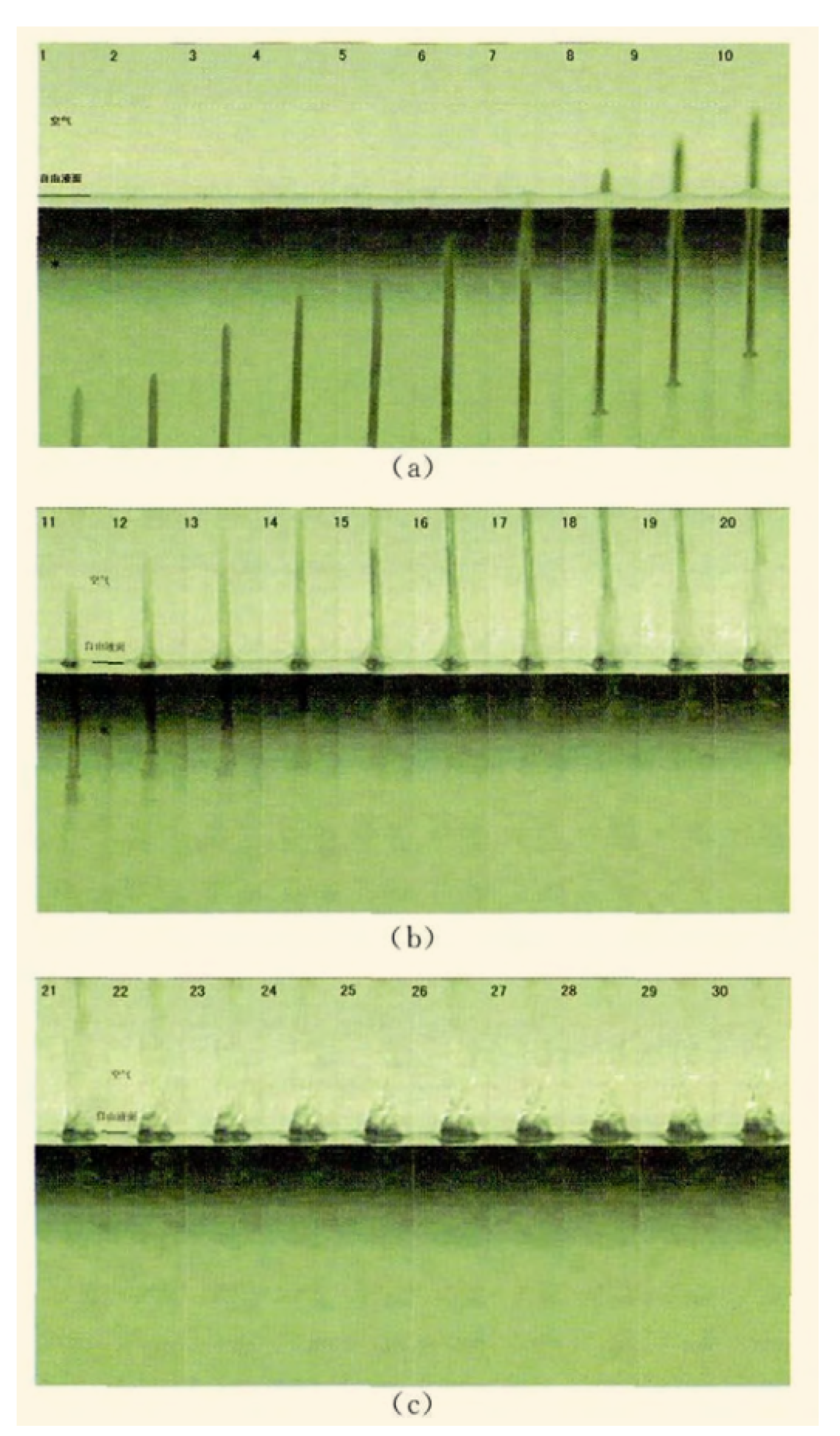
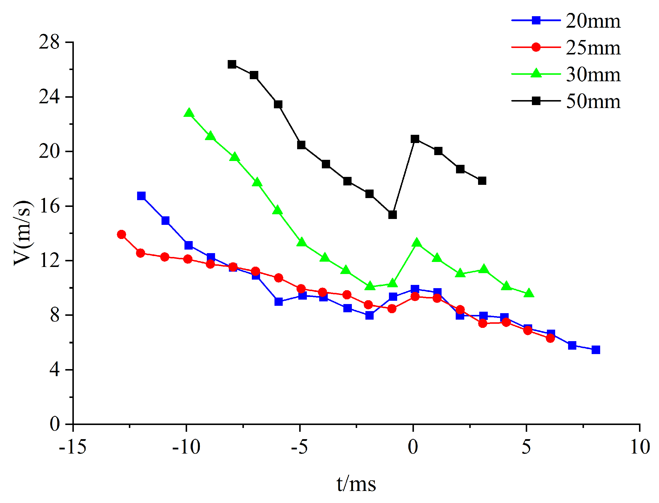
Shi et al.[
57] conducted experiments on
,
,
, and
length nails with vertical water exit at initial speed of 14-30 m/s through their self-designed super cavity generation device (
Figure 9). The evolution of the velocity was obtained (
Figure 10), the jump in velocity after water exit was captured and the cavity generation, evolution, and collapse process was also analyzed.
Furthermore, Shi et.al[
63]also conducted water exit experiments on slender blunt-headed nail bodies with length-diameter ratios of 8-12 at different initial velocities (23-29 m/s) and different attack angles by their self-designed super cavity generation water exit device. In experiments, the velocity and drag coefficient evolution were obtained and the velocity jumping phenomenon after water exit was captured, which can be explained theoretically through the equation of motion and momentum conservation. Subsequently, the group conducted high-speed (41.03 m/s-79.32 m/s) projectile vertical water exit experiments[
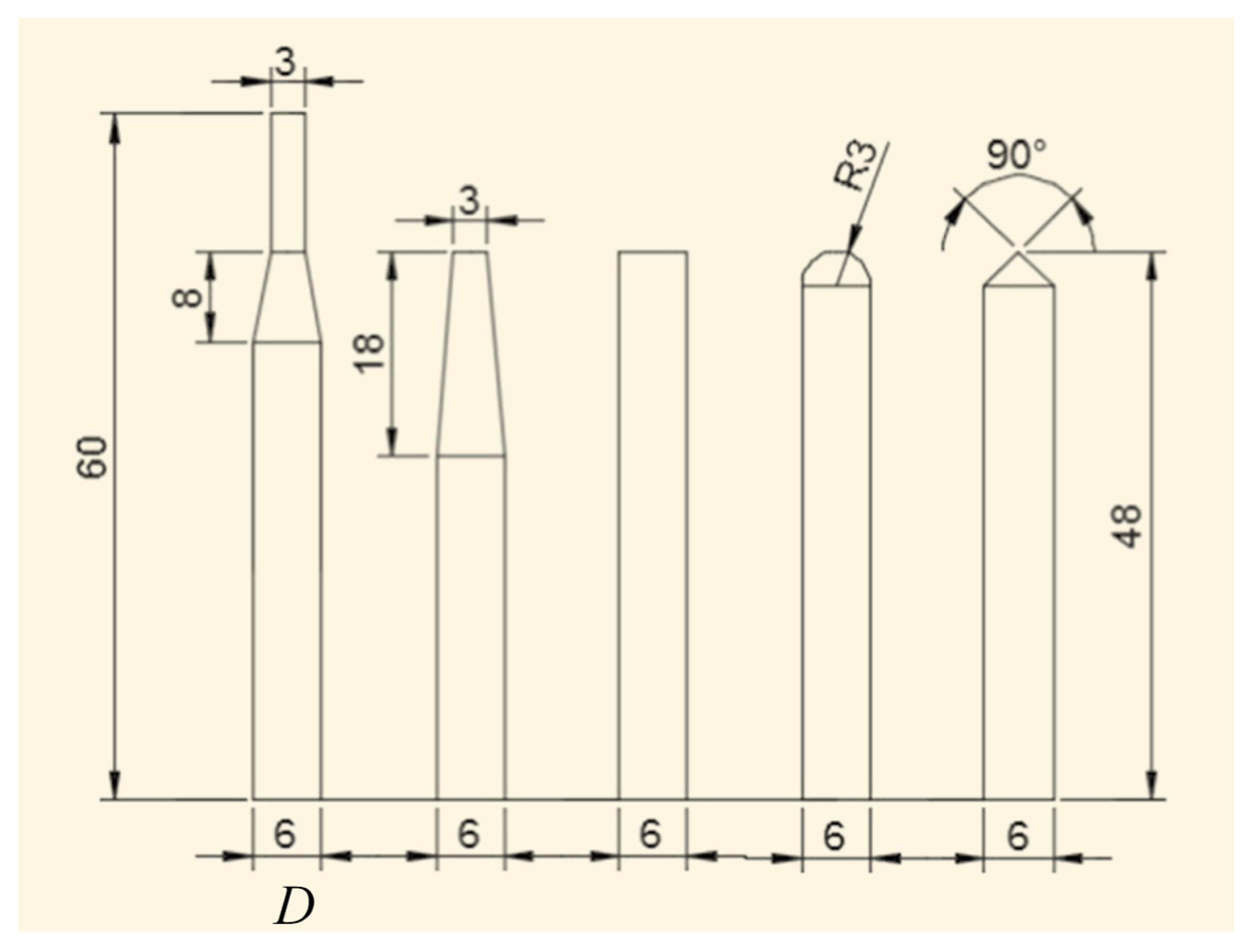
58] for different head types (
Figure 11) on the basis of the developed high-speed projectile water exit experimental setup and obtained the velocity variation curves. Accordingly, the empirical formulas for the cavitation number
and drag coefficient
C were fitted based on the empirical formulas obtained by Reichardt[
78] and Logvinovich [
79]. Shi [
80]et al. continued to further study the cavity evolution of the water exit process of high-speed projectiles with a richer projectile head type (
Figure 12). Furthermore, by increasing the projectile velocity (100 m/s-150 m/s) based on the experimental setup of high-speed projectiles, the velocity, drag, and cavity displacement variation curves of the projectile were obtained. The experimental results show that the velocity of hemispherical head type projectile decays the least and cavity diameter is the least, the blunt disk type decays the most and cavity diameter the most, while the projectile velocity is almost constant after water exit for all, which is consistent with the theoretical results obtained by May[
81].
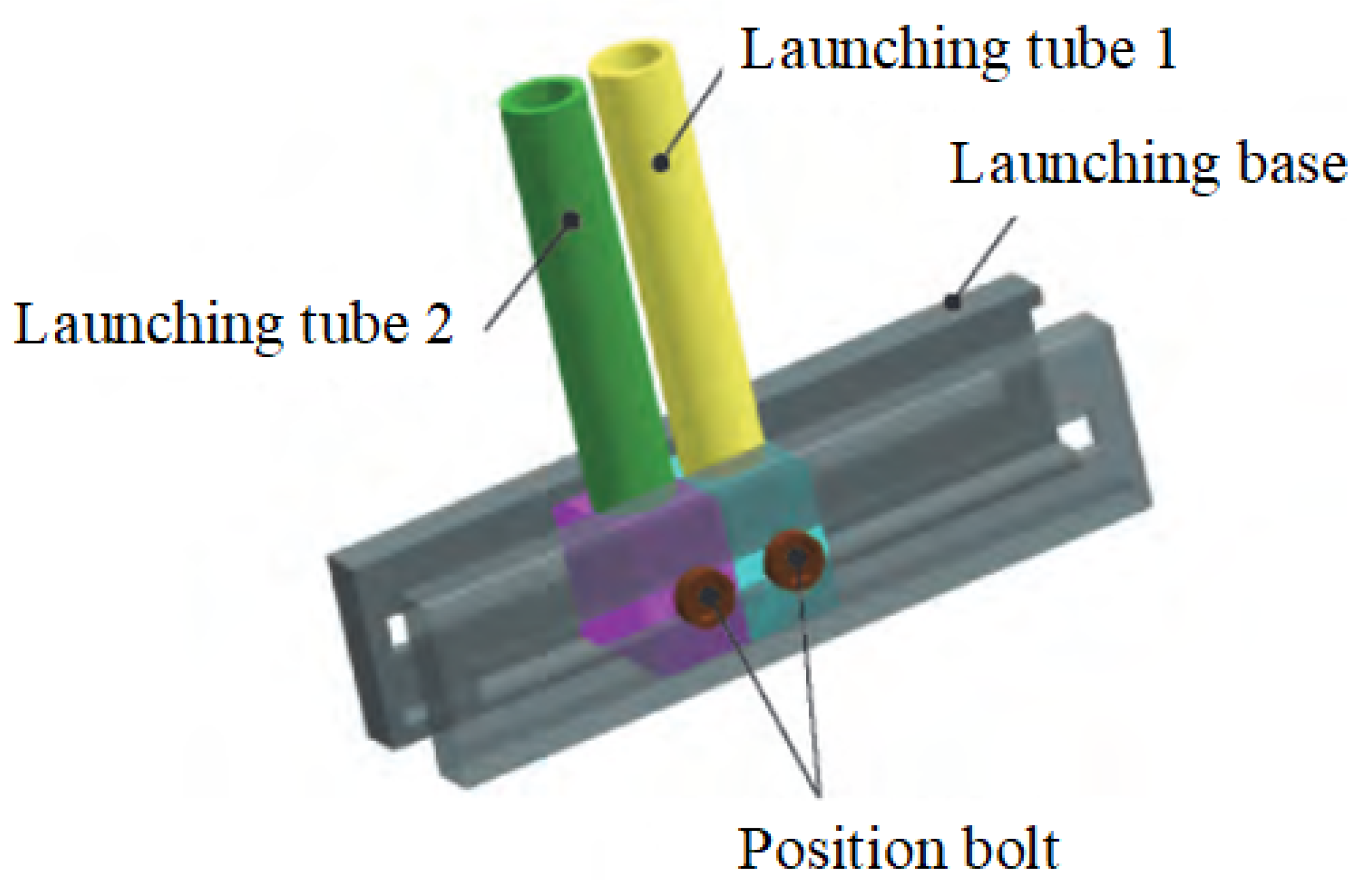
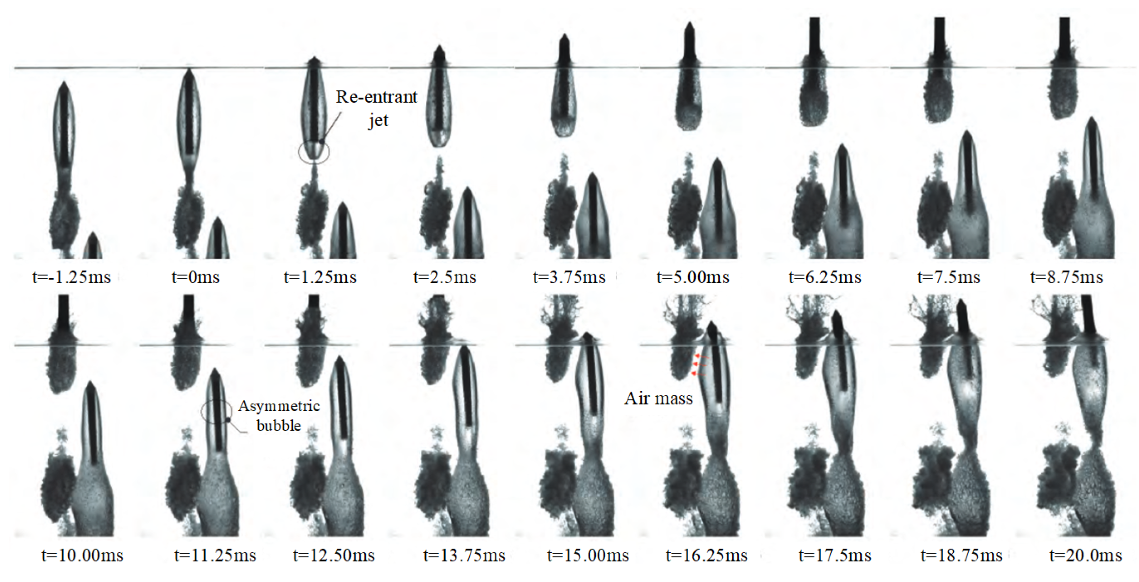
The study of the water exit problem of a rotating body with initial horizontal velocity is of great importance in military applications. Still, few relevant experiments have been conducted. The experimental study of rotating body by Lu et al.[
82]has filled the gap in this area. Based on their own experimental facilities, Lu has experimentally studied the cavity evolution and ballistic characteristics during the vertical water exit of single and twin-launch rotating bodies at an initial velocity of 15m/s and the effect of initial horizontal velocity (0.5m/s) by controlling the movement of the underwater launch base (
Figure 13). The results show (
Figure 14) that the cavity and ballistic characteristics of the first shot are basically the same as those of the single shot. The development of the cavity of the second shot is significantly asymmetric due to the effects of the first shot. With an initial horizontal velocity, the trajectory revolution of the second shot is less deflected by the combined effect of pressure difference and initial velocity compared with the first shot under the same condition.
3.3. Cavitation
From some aforementioned experiments, it can be observed that cavitation accompanies the process of water exit, exerting a significant impact on the trajectory and load. In the engineering practice, it has a wide application in the field of noise reduction, drag reduction and destruction prevention of the structure[
83,
84,
85,
86], which therefore becomes the focus of engineers and scientists. However, effected by factors including size and velocity of objects, the flow field and so no, the occurrence of cavitation, as well as the development of trajectory and morphological transformations of cavitation, are rendered highly complex, which makes the research into cavitation challenging. This section briefly summarize the patterns of formation and morphological development of cavitation. Since cavitation is often accompanied by object motion, the cavitation described in this section refers to the cavitation accompanying the periphery of a moving object.
3.3.1. Formation of the Cavitation
The causes of cavitation around the spacecraft include many factors, and the current academic community has not yet reached a clear and complete conclusion on the mechanism of occurrence. Factors such as temperature, liquid compressibility, flow velocity, viscosity, cavitation nuclei, solid wall properties, and local static pressure all have a significant impact on cavitation. Among them, cavitation nuclei and local static pressure play a key role in the formation of cavitation[
87].
Different from the phase change process like evaporation or boil, cavitation occurs inside the liquid or near the boundary of objects. Cavitation can only occur when the pressure of the liquid drops below the saturated vapor pressure at the current temperature[
88] . Experimental results have shown that in some cases like stationary pure liquids, cavitation is hard to occur even if the pressure drops below the saturated vapor pressure at the current temperature. Thus another necessary condition for cavitation is the existence of cavitation nuclei. The existence of cavitation nuclei reduces the tensile strength of the liquid at the current temperature, making it a weak point inside the liquid, for which Knapp[
88] and Harvey [
89,
90,
91] have conducted a series of experiments and explanations were given. When the liquid pressure drops below the saturated vapor pressure, cavitation occurs at the weak point, i.e., the cavitation nuclei. The main components of cavitation nuclei in the liquid are free bubbles of non-condensable gases, which are the basic conditions for cavitation and have become a consensus in the field of cavitation research[
92].
3.3.2. Description of Cavitation
In order to better describe the cavitation state and characterize the dynamic similarity index of cavitation, the cavitation number was proposed is as follows[
93],
where
and
represent the reference pressure and reference flow velocity of the liquid at a point where it is not disturbed by the moving object, respectively.
is the saturated vapor pressure at the current temperature, and
is the liquid density.
The cavitation number can represent the similarity of cavitation scenes between two water flow systems under certain conditions. With the same Reynolds number, Weber number, and other similarity criteria are equal, if the cavitation numbers of the two water flow systems are also the same, it can be theoretically considered that their cavitation phenomena are the same. However, in practice, when the size ratio of the two water flow systems changes, the cavitation phenomenon at the same cavitation number may show significant inconsistencies, exhibiting a clear "scale effect"[
94].In the sub-cavitation flow field, if the cavitation number is reduced by only lowering the pressure or increasing the flow velocity until the flow field shows tiny visible cavities, this state can be identified as "incipient cavitation," and the corresponding cavitation number at this moment is called the "incipient cavitation number." However, during the experimental process, it was found that the values of are quite dispersed and have poor repeatability due to factors such as water quality and flow conditions. It was discovered that the cavitation number
is more suitable as a sign of cavitation occurrence due to good repeatability[
95,
96].
3.3.3. Type of Cavitation
Considering the physical characteristics and occurring condition, the cavitation can be classified into four types, i.e, traveling cavitation, fixed cavitation, vortex cavitation, and vibratory cavitation[
88]. According to the cavitating state inside the water and near the solid boundary, the cavitation can also be classified into sub-cavitation state (cavitation doesn’t occur yet), critical cavitation state (cavitation begin to occur ), local cavitation state (cavitation occurs inside the water or near the solid boundary) and super cavitation state[
97]. Self and Ripken et al[
98] have conducted mounts of experiments on the relationship of the cavitation number and the size of super cavitation on the smoothed sphere’s surface, indicating that the relationship is less influenced by the scale effect.
3.4. Discussion
With the efforts of scholars, the experimental devices of water exit involving various types of objects (flat, blunt, conical) and different velocities were designed. The typical phenomena during the water exit, such as liquid surface lift, liquid surface breaking, cavity generation and evolution, and velocity jump, can be clearly captured. Beside, PIV, depressurized setup, super cavity generation device, and other experimental technical means are emerging, which greatly promote the research of water exit problem and provide reliable and real data for theoretical research and numerical simulation. The existing experimental equipment have enabled us to effectively observe and analyze many phenomena and concerned data in the water exit process, and some results can provide guidance for industrial and military applications. However, regarding the cost and the difficulty of experiments, , the size and exiting speed of the object are always scaled which is different from practice. Furthermore, there is still a lack of effective experimental studies on the structural force response of objects under fluid-structure coupling, which is one important concern in engineering applications. Above all, we can make improvements and breakthroughs in the following aspects when redesigning experimental equipment and carrying out water exit experiments.
(1) In actual situations, the hydrological conditions that the navigators face are extremely complex, accompanied by wave surges, ocean currents and even strong winds, rather than being as calm as that in the experimental tank. Therefore, when conducting the water exit experiment, the wave-maker can be used to simulate different hydrological conditions to study the water exit process of the navigators. If possible, it will be better to establish a test station in the real water area[
33].
(2) Many countries paid great attention to the drag reduction technology through supercavitation. However, the speed of the object in the water exit experiments is usually not enough to produce supercavitation that can cover the whole body. In current experiments, the cavitation is mainly induced passively by two means: one is to adjust the ambient atmospheric pressure in the depressurized setup, and the other is to increase exiting speed while have to reduce the size of the object significantly. Active cavitating technology at different speeds and sizes has a wide application in engineering . However, how to ensure the stability and controllability of the object in supercavitating state is the focus of the technology. The development of relevant experimental equipment is of great significance to solve this problem.
(3) At present, the objects are regarded as a whole body in most of water exit experiments and the overall force and motion parameters are mainly paid attention to. However, the impact or even damage to the local structure of the object is lack of consideration. Therefore, how to monitor the stress response to the object structure is worthy of our further research.
4. Numerical Simulation
Due to the nature of low cost, high efficiency, and flexibility, the numerical simulation indeed has unique advantages, and has already become an indispensable tool for solving engineering problems nowadays. Therefore, many scholars have also done plenty of numerical researches on the water exit problem[
99,
100,
101,
102]. In 1965, Moran[
103]reviewed the mathematical theory of the water exit process and concluded that it was difficult to accurately calculate the loads on the object during water exit in theory and suggested solving the NS equation by numerical simulation and then comparing it with experimental results. However, the physical processes involved in the water exit process are rather complicated where the liquid surface breaks up and the water body separates, for which the mesh distortion will occur when traditional numerical methods are performed. Latest numerical methods such as BEM usually terminate when liquid surface breaks up[
59], while meshless methods such as SPH(Smoothed particle hydrodynamic methods) are unable to effectively simulate the whole process of water exit due to the numerical oscillations and accuracy.
Several numerical methods that have been used successfully in the numerical simulation on the water exit problem are introduced in this section, namely MPS (Moving Particle Semi-implicit), VOF (Finite volume method), and FLUENT with LES.
4.1. BEM Method
The theoretical basis of the BEM method is integral equation theory inspired by the idea of discretization from FEM (Finite element method). Different from FEM, BEM method is a boundary-type numerical method that discretizes the integral boundary equation into a group of algebraic equations by dividing the mesh on the boundary of the calculation region, which is also the most important feature of BEM method, namely dimension reduction. The spatial and planar problems can be transformed into two-dimensional problems on the boundary interface of the calculation region and one-dimensional problems on the boundary line respectively through BEM method. Compared with region-based numerical methods such as FEM and FDM(Finite difference method), we only need to divide the mesh on the boundary rather than discretize in the whole region in BEM method. Thus, not only the dimension of the problem is reduced, but also the difficulty of discretizing models is overcome. Therefore, BEM method has a great advantage in solving problems with complex boundaries, interface, and shapes, which is considered the application in the solution of water exit process problems by many scholars.
Early in 1976, Longuet et al. [
104]made a preliminary exploration of the process of neutral objects penetrating the free liquid surface with the axisymmetric BEM method. Ye [
105]applied nonlinear boundary conditions to numerically calculate the vertical water exit problem of an axisymmetric object in arbitrary shape with the BEM method. Later, based on the small-angle regression method, Ye et al. [
106]also studied the three-dimensional water exit problem, and the process of water exit until it approaches the free liquid surface was simulated using the BEM method. Greenhow and Moyo[
107]and other scholars[
108] studied the two-dimensional forced vertically water exit problem of cylinder with uniform velocity under both full and semi-submerged conditions using the BEM method. Their studies analyzed the free liquid surface deformation phenomenon and compared it with the analytical solution based on the small-time expansion method by Peder et al. [
109], which are in good agreement. Liju et al. [
59,
110]used the BEM method to investigate the water exit problems of a two-dimensional axisymmetric object with constant velocity and constant acceleration conditions. However, until then, the numerical simulations of the water exit problem by the BEM method were numerically terminated before the break up of free surface or the penetration of the object into the liquid surface. The reason is that the water layer at the front of the object becomes thinner and thinner as the object rises before the object penetrates the liquid surface and the liquid surface breaks up. In this process, the scale of physical problem decreases to the micron level[
59], making both experimental image capture and numerical calculations challenging.
Inspired by[
111,
112], Wu et al. [
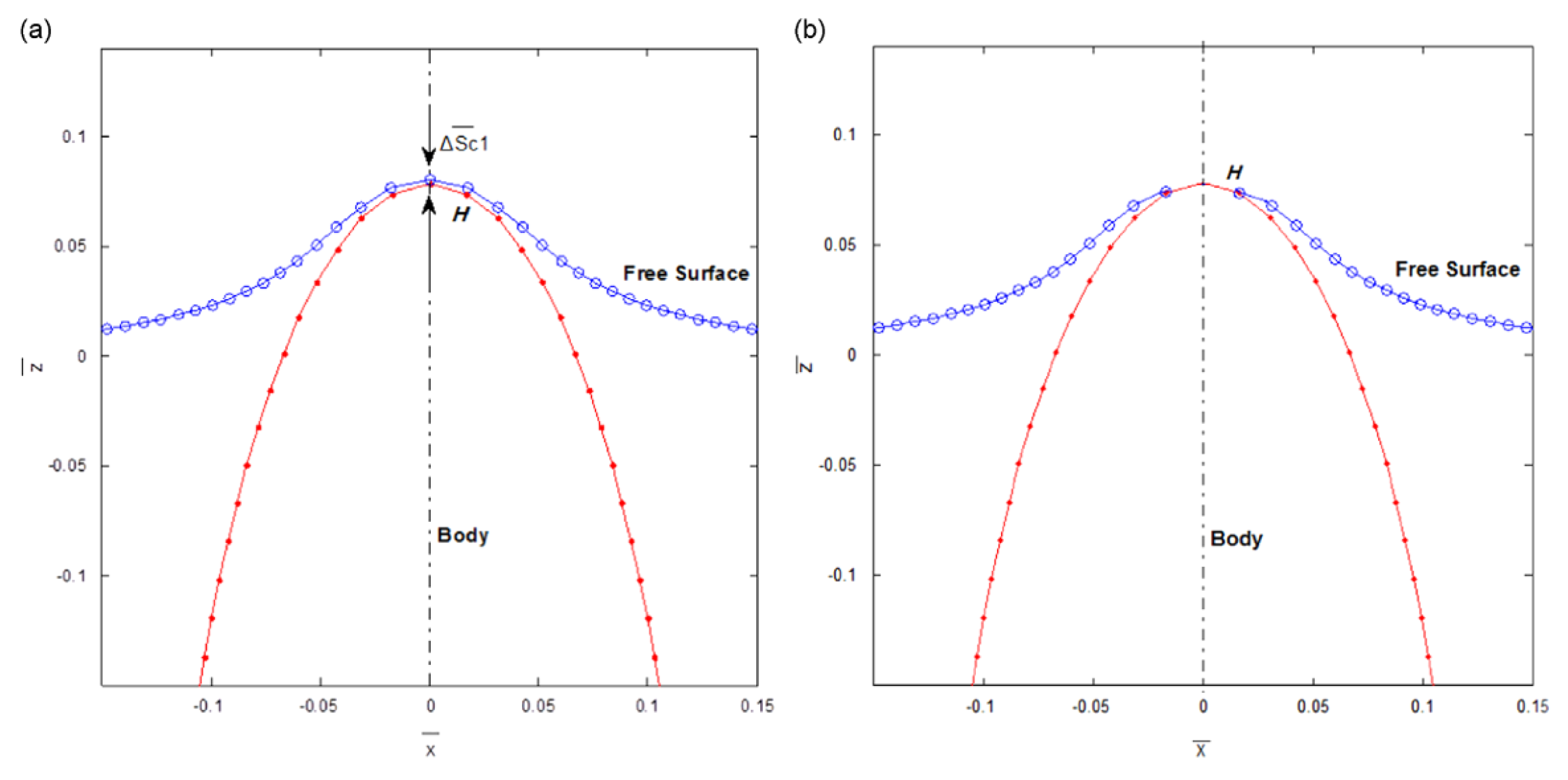
74]proposed the liquid surface fragmentation and solid-liquid separation algorithm, which was applied to the BEM method by setting the minimum water layer thickness (as shown in
Figure 15,
Figure 16) as the criterion between liquid surface fragmentation and water body separation. The whole process of water exit of a light ellipsoid with different ratios was successfully simulated, including the phenomena of free liquid surface breaking, water body separation, free surface oscillation, and jet development were successfully captured [
113], and good convergence is obtained.
However, it can be seen from the above that when the BEM method is used to calculate the water exit problem, the velocity of the object is still low, less than 10 m/s. Therefore, the phase change and cavitation phenomena arising from the high velocity in the water exit process are nearly not been studied.
4.2. VOF Method
As a well-established numerical method, VOF method is widely used in fluid-solid coupling, multiphase flow, and heat transfer problems. Therefore, many scholars have also applied it to the solution of the water exit problem.
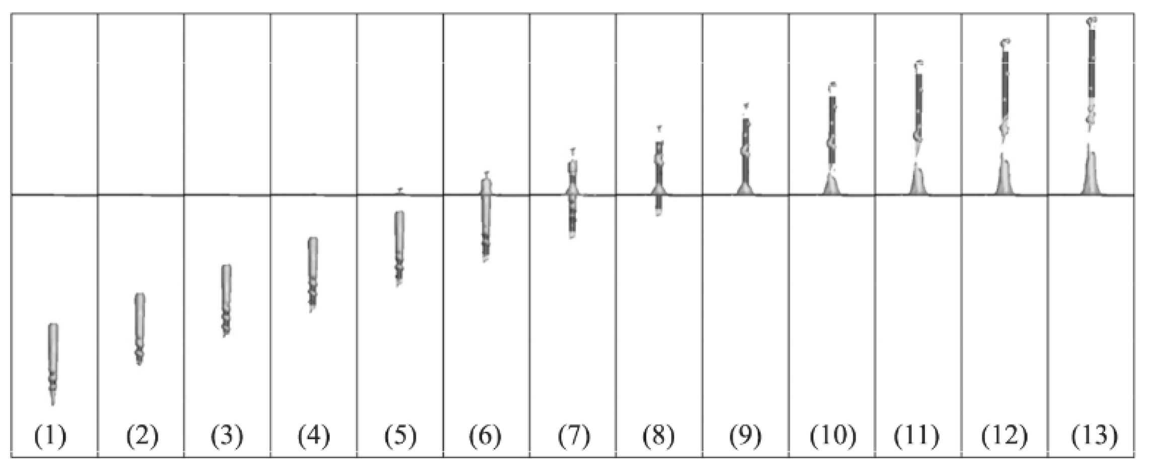
Tassin et al.[
46]used the VOF solver in OpenFoam to solve the gas-liquid two-phase flow. The dynamic grid technique was applied to solve the fluid-solid interaction problem of moving objects. The water entry and water exit problems for wedges whose shape can change with time were simulated, which agreed well with the forces predicted by the theoretical solution. However the theoretical solution of the water exit stage didn’t not always match the numerical solution. Based on the OpenFoam open-source library, Piro et al.[
114]used the FEM method for the fluid-solid weak coupling problem and the VOF method for the free interface problem , in which the fluid is assumed laminar and incompressible. Numerical calculations were performed for rigid and elastic wedges with constant acceleration water entry and water exit problems, respectively, regardless of the effects of gravity, viscosity, and turbulence. Compared the numerical solution of the force and splash location of the object during water entry with the theoretical solution of Wanger[
28,
48]and the numerical solution of the wetted region during water exit with the theoretical solution[
6], good agreements are achieved.
Shi [
63]applied the VOF multiphase flow model, the Schnerr-Sauer cavitation model and the mesh reconstruction method to numerically simulate the slender body water exit problem, in which the generation and evolution of cavitation and the water pressure changes were analyzed. However the cavitation model is a natural cavitation model, and the effect of the interaction with the atmosphere on cavitation after the object water exit was not considered. Meanwhile, based on the data obtained by specific speed (41.03m/s-79.32m/s) projectile experiments as known conditions, the group[
58] also applied the dynamic mesh technique and the VOF multiphase flow model to calculate the slender body high-speed water exit problems, in which the turbulence was considered. The cavity shedding and water splashing were in good agreement with the experimental phenomena (see
Figure 17 ).
Based on Fluent software with SST
turbulence model and VOF method to capture the free liquid surface, Ma et al.[
115]established a model for the cross-media motion of the slender body and the slender body water exit problem was numerically calculated. The effects of attack angle and angular velocity on the attitude of water exit were investigated. Compared with the results of the BEM method and experimental results, respectively, the velocity, acceleration, and attack angle variation patterns were in good agreement, and the velocity jump at the end of the water exit was observed. With VOF method, Shi [
80]used the Schnerr-Sauer cavitation model and the 6-DOF method to investigate the super cavitation problem during water exit with different head types, which were generally consistent with the experimental phenomena. The velocity and displacement evolution of the cavitation projectile during the water exit process were compared with the experimental data and semi-empirical formulae, and the agreement was good as well.
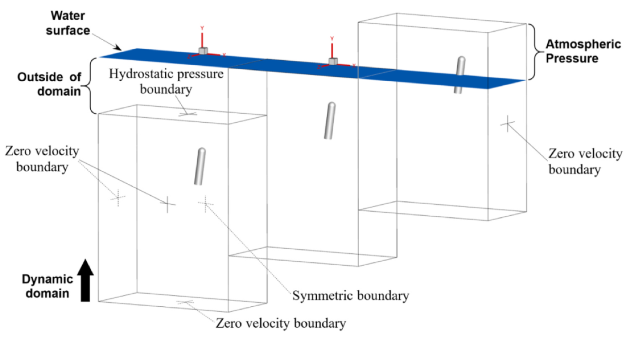
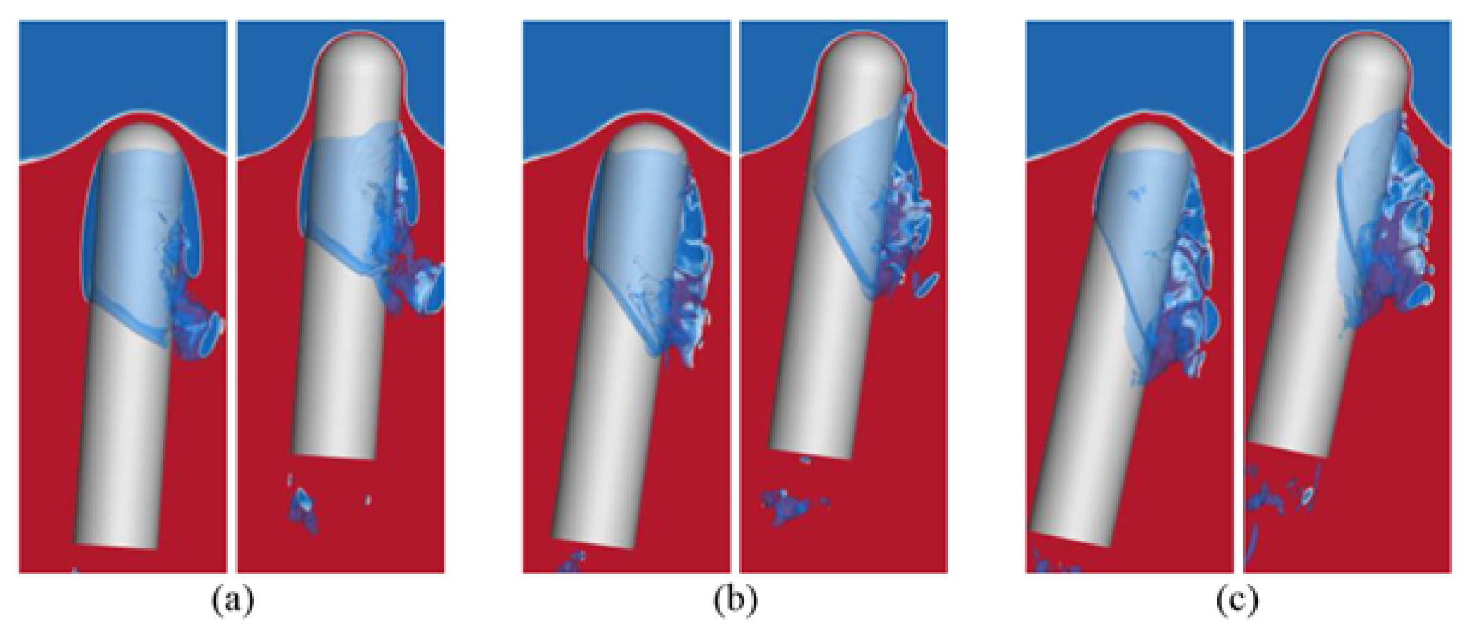
4.3. FLUENT with LES
Turbulence has a significant effect on energy exchange, dissipation, and Reynolds stress. In the process of water exit, when the object’s velocity increases, the Reynolds number will also increase, thus the turbulence will be more obvious. Normally, VOF, BEM, and other methods are not sufficiently advantageous in turbulent flow simulation. In order to simulate turbulent flow, it is required that the size of the computational region should be large enough to contain the largest vortices in the turbulent flow. Meantime, the size of the computational mesh should be small enough to distinguish the motion of the smallest vortices. Large-scale eddies have a large effect on the mean flow, while small-scale eddies mainly play a role in dissipation. At present, the minimum scale of the computational mesh is still much larger than the scale of the smallest eddy, making it difficult to perform direct full-scale simulations of it. Hence there LES method was born. Based on isotropic grid uniform filtering of octree and a high-resolution interface capture algorithm[
100], the whole process of the submarine-launched missile from water into air with LES method was simulated by Chen[
116] (see
Figure 18,
Figure 19). The effects of launch depth, angle of attack, and initial velocity on the flow field around the projectile and the evolutionary development pattern of the cavity were explored.
4.4. Discussion
In addition to the above studies, other scholars have also achieved some results with FDM and SPH methods. In order to simulate the cavity generation and evolution during the water exit process, the BUBMAC method[
117] and the FLUENT multiphase flow cavitation model[
118] were used to calculate the water exit problem of a long cylinder numerically. Regarding the cylindrical and free-surface action problem as multiphase flow, Zhu et al. [
108]used the FDM method, based on CIP (Constrained Interpolation Profile), to numerically simulate the two-dimensional horizontal cylindrical water exit and water entry problem. Among them, the numerical results of water exit subjected to constant force were compared with the experimental results in Ref[
52], in which the phenomena as well as the displacement evolution agrees well. The numerical results of uniform water exit were compared with the experimental results in Ref[
64], in which the impact coefficients were well matched. Jafar et al.[
119]applied the SPH method (Smoothed particle hydrodynamics method) to simulate the water exit problem of two-dimensional rotating cylinder with the SPS turbulence model. The effects of the parameters like depth, column density, vertical velocity, horizontal velocity on the vortices, velocity components of the flow field and free liquid surface of the cylindrical wake were analyzed. Wu et al.[
120]have studied the water exit problems of slender body with SPH method to investigate the effect of different motion parameters on the hydrodynamic characteristics by changing the velocity and the attack angle. Also Josip [
121]and other scholars used the ISPH(Incompressible SPH) method to numerically simulate the water exit problem of a cylinder with constant velocity and the free liquid surface motion and force evolution law were analyzed.
The influence of hydrodynamic loads on the stress response and distribution of the structural body during water exit is of great importance for the design of structural bodies. To address the problem of treating the water exit object as elastic rather than rigid, combined a flow field solver based on the FVM and a structural solver based on the FEM, Hu et al. [
122]have studied the water exit problem of an elastic flat-headed cylindrical shell with cavity at certain attack angle. The deformation characteristics of the structure under the action of hydrodynamic loads and the coupling relationship between the hydrodynamic properties and the structural vibrations were demonstrated in their researches.
Although a lot of studies have been conducted on the water exit problem numerically, it can be known there still exist several problems in the following aspects. Firstly, the study of the water exit problems of elastic bodies is relatively limited. To the best of out knowledge, only Hu’ s researches have been involved[
122]. Secondly, the velocities encountered in water exit problems are basically low(below 50m/s), wheras higher velocities (above 50m/s) have been rarely studied.
5. Conclusion
The water exit problem is one of the critical topics in the study of interactions between navigable bodies and water flow, which is of great significance for marine ships and underwater vehicles. Numerous scholars have extensively investigated this issue from various perspectives, yielding substantial findings. In this paper, we provides a comprehensive review of these findings from three aspects: theoretical research, experimental development, and numerical simulation. The research outcomes are systematically organized and analyzed according to a problem-oriented framework.
(1) In the aspect of theoretical analysis, obtaining a theoretical solution to the water exit problem is challenging due to its highly nonlinear nature. When considered as the inverse of the water entry problem, the solution is linearly unstable. Simplified approaches, such as the improved von Karman model and the linearized water exit model, have been proposed to address this issue. While these models show good agreement with corresponding experimental results, their validity is restricted to specific conditions: two-dimensional scale, initially semi-submerged state, low-velocity water exit, and neglect of gravity and viscosity effects.
(2) In the aspect of experimental research, there are several ways to drive the object’s water exit, including automatic floating of neutral objects, thin rope or rod traction, L-shaped rod propulsion, etc. However, these methods typically result in low object velocities and some related equipment will disturb the flow field, while higher exiting velocities can be achieved through air pump ejection. To gather experimental data, fully transparent devices and LED edge lighting are often employed. And the flow field morphology, object velocities, displacement and other parameters can be acquired through the high-speed camera. Additionally, PIV(Particle image velocimetry) technology is utilized to provide fluid velocity fields, from which fluid pressure fields can be inferred. In order to observe the cavity evolution at low velocity, the depressurized experimental platform is designed.
(3) In the aspect of numerical simulation, water exit problems involve a multiphase coupling process, characterized by water separation, liquid surface fragmentation, phase changes, and other complex phenomena. The traditional mesh numerical methods suffer from mesh distortion, leading to numerical termination. In this paper, three numerical methods are introduced. The BEM method can reduce the dimensionality of high-dimensional problems but is limited by low water exit velocities and the exclusion of phase change and cavitation factors. The VOF method, enhanced by the Schnerr-Sauer cavitation model, dynamic mesh and mesh reconstruction techniques, can partially address the water exit problems. However, it struggles with accurately capturing flow field morphology. The LES method can capture the eddy and cavity evolution in the water exit process and worth further study.
To study the water exit problem, it is essential to clarify the intrinsic mechanics, with the aim of providing reliable references for the design and manufacture of navigable bodies. In order to promote further research on this problem, there are still some difficulties to overcome. Firstly, the development of water exit theory is progressing slowly , and the theoretical solution of the pure water exit process needs to be further explored by scholars. Secondly, current methods for acquiring experimental data in the water exit process is limited, particularly regarding the elastic structural effect of objects. The difficulty in observing and obtaining stress responses poses significant challenges for industrial design and manufacturing. Additionally, while numerical simulations of the water exit problem hold great promise, existing methods fall short in fully simulating cavitation phenomena, fluid-solid-gas three-phase coupling, and liquid surface deformation and fragmentation. Future development should be focused on integrating mesh-based methods (such as VOF) with meshless methods (such as MPS, SPH, etc.) to address these difficulties. Lastly, meshless methods, such as SPH, have unique advantages in simulating problems with large deformation. However, they currently lack appropriate models for phase change and cavitation problems. Since the structural response of objects is crucial in the water exit problem, coupling meshless methods like SPH presents a promising future for further researches.
references
Author Contributions
investigation, Hualin Zheng; data curation, Hualin Zheng; writing—original draft preparation, Hualin Zheng; writing—review and editing, Hualin Zheng and Yujie Zhu; visualization, Hualin Zheng; supervision, Hongfu Qiang and Chi Zhang; project administration, Yujie Zhu; funding acquisition, Yujie Zhu and Hongfu Qiang. All authors have read and agreed to the published version of the manuscript.
Funding
This research was funded by the national natural science foundation of China (Grant No.12302383, 92152201, 52375559), national natural science foundation of Shannxi Province (Grant No. 2023-JC-QN-0052), postdoctoral science foundation (Grant No. 2023M734284) and Youth talent support of Shaanxi Province (Grant No.20230519).
Institutional Review Board Statement
Not applicable.
Informed Consent Statement
Not applicable.
Data Availability Statement
None.
Acknowledgments
The authors acknowledge the technical support from Zhijian Laboratory of Xi’an Research Institute of Hi-Tech. We are grateful to anonymous referees and the editor who provided valuable comments improving the manuscript.
Conflicts of Interest
The authors declare no conflicts of interest.
References
- Kuklinski, R.; Henoch, C.; Castano, J. Experimental Study of Ventilated Cavities on Dynamic Test Model. 2001.
- Cong, M.; Wei, G. Supercavitation Research Program of the US Navy. Aerodynamic Missile Journal 2009, 1, 17–20.
- Zhu, J. Current Status of Research on German Supercavitation Underwater Weapons. Mine Warfare and Ship Protection 2005, 4, 12–17.
- Kulkarni, S.S.; Pratap, R. Studies on the dynamics of a supercavitating projectile. Applied mathematical modelling 2000, 24, 113–129. [CrossRef]
- Yao, G.; Li, Y.; Zhang, H.; Jiang, Y.; Wang, T.; Sun, F.; Yang, X. Review of hybrid aquatic-aerial vehicle (HAAV): Classifications, current status, applications, challenges and technology perspectives. Progress in aerospace sciences 2023, p. 139. [CrossRef]
- Karman, T.V. The impact of seaplane floats during landing. Technical Report Archive and Image Library 1929.
- Wei, Y.J; MIN, J.W.C.Z.Y.F. Research on cavitation of vertical launch submarine missile. Engineering Mechanics 2009, 26, 251–256.
- MIN, J.X;Wei, Y.C.W.Z. Numerical Simulation on Hydrodynamic Characteristics of Submarine Missile in the Vertical Launch Process. ACTA ARMAMENTARII 2010, 31, 1303–1309.
- Liu, H.J;Wang, C.Z.B.B. Numerical investigation on the hydrodynamic characteristics of a cylinder of different head construction out of launch tube. Journal of Harbin Engineering University 2012, 33, 6.
- LI, R. Research on the Flow Field and Ballistic Characteristics of the Gas-Steam Ejection. PhD thesis, Nanjing University of Science and Technology, 2019.
- Zhao, Y. The Research on Hydrodynamic Characteristics of Sharing Launched Submaring-Launched Vehicle. PhD thesis, Harbin Institute of Technology, 2014.
- Shang, R. Numerical Simulation on Hydrodynamics Characteristics of Ventilating Submaring-Launched Vehicle in the Vertical Launch Process. PhD thesis, Harbin Institute of Technology, 2013.
- Liu, Z.Y; Yan, K.W.B. Numerical simulation of the development process of a trailing cavity from generation to separation. Journal of Ship Mechanics 2005, 9, 8.
- Chen, W.Q; Wang, B.Y.K.Y.S. Research on Unsteady Vertical Cavitation in Cavitator Effluent. Chinese Journal of Theoretical and Applied Mechanics 2013, 45, 7.
- Glasheen, J.W.; McMahon, T.A. A hydrodynamic model of locomotion in the Basilisk Lizard, 1996.
- Rosellini, L.H.F.C.C. Skipping stones, 2005.
- Cole, A.M.W.S. Impact with a liquid surface studied by the aid of instantaneous photography. Paper II, 1900.
- May, A.; Woodhull, J.C. The Virtual Mass of a Sphere Entering Water Vertically, 1950.
- May, A. Effect of Surface Condition of a Sphere on Its Water-Entry Cavity, 1951.
- Wei, Z.; Hu, C. Experimental study on water entry of circular cylinders with inclined angles, 2015.
- Wei, Z.; Hu, C. Experimental study on water entry of circular cylinders with inclined angles, 2015.
- TRUSCOTT, TADD T, T.A.H. Water entry of spinning spheres, 2009.
- Sun, L.; Wang, D.; Chen, Y.; Wu, G. Numerical and experimental investigation on the oblique water entry of cylinder, 2020.
- Dai, D.; Tong, A.Y. Analytical interface reconstruction algorithms in the PLIC-VOF method for 3D polyhedral unstructured meshes, 2019.
- Yu, P.; Li, H.; Ong, M.C. Numerical study on the water entry of curved wedges, 2018.
- Oliver, J.M. Water entry and related problems. University of Oxford 2002.
- Ni, B.Y; Wu, G. Numerical simulation of water exit of an initially fully submerged buoyant spheroid in an axisymmetric flow. Fluid Dynamics Research 2017, 49. [CrossRef]
- Wagner, H. Landing of Seaplane 1931.
- Kuklinski, R.; Castano, J.; Henoch, C. Experimental Study of Ventilated Cavities on Dynamic Test Model. Cancer Research 2001.
- Zhan-Ying, W.; Jian-Hua, F.; Shao-Hua, C.; Hai-Peng, W.; Tian-Qing, Y. Study on Binary-State Pitching Movement of Water-Exit Trajectory of Underwater Vehicles. Journal of Ordnance Equipment Engineering 2016.
- HU, J.H; Xu, B.F.J.J.C. Research on Water-Exit and Take-off Process for Morphing Unmanned Submersible Aerial Vehicle. China Ocean Engineering 2017, 31, 202–209. [CrossRef]
- Sun, X.; Cao, J.; Li, Y.; Ling, Y. Efficient prediction method for the water-exit characteristics of unmanned aerial–underwater vehicles. Ocean Engineering 2024, 302, 117403. [CrossRef]
- Fu, J. Unknown Title. Research of German Supercavitation Weapons in the Water 2005, 6, 12–17.
- Kulkarni, S.S.; Pratap, R. Studies on the dynamics of a supercavitating projectile. Applied Mathematical Modelling 2000, 24, 113–129. [CrossRef]
- Yan, K. Principle and Method of Nuclear Seeding in Cavitating Water Tube — Review of French Research. Journal of Ship Mechanics 1999, 3, 78–82.
- Wei, Z. Lifting-principle-based design and implementation of fixed-wing unmanned aerial–underwater vehicle. Journal of Field Robotics 2022, 39, 694–711. [CrossRef]
- Zhang, G.; You, C.; Wei, H.; Sun, T.; Yang, B. Experimental study on the effects of brash ice on the water-exit dynamics of an underwater vehicle. Applied Ocean Research 2021, 117, 117. [CrossRef]
- Moran, J. Line source distributions and slender-body theory. Journal of Fluid Mechanics 2006, 17, 285–304. [CrossRef]
- Moran, J. Addendum - the vertical water-exit and entry of slender symmetric bodies. AIAA Journal 1964a, 2, 1480–1482. [CrossRef]
- Moran, J. Image solution for vertical motion of a point source towards a free surface. Journal of Fluid Mechanics 2006, 18, 315–320. [CrossRef]
- Moran, J. The Vertical Water-Exit and -Entry of Slender Symmetric Bodies. Journal of the Aerospace Sciences 1961, 28, 803–812. [CrossRef]
- Martin.; Greenhow.; .; .; Li.; Yanbao. Added masses for circular cylinders near or penetrating fluid boundaries—review, extension and application to water-entry, -exit and slamming. Ocean Engineering 1987, 14, 325–348. [CrossRef]
- Yang, J.; Feng, J.; Li, Y.; Liu, A.; Hu, J.; Ma, Z. Water-Exit Process Modeling and Added-Mass Calculation of the Submarine-Launched Missile. Polish Maritime Research 2017, 24, 152–164. [CrossRef]
- Li, J; Lu, C.H.X. Calculation of added mass of a vehicle running with cavity. Journal of Hydrodynamics, Ser. B 2010, 22, 312–318. [CrossRef]
- Takamure, K.;Uchiyama, T. Calculation model for water mass entrained by the water exit of a particle using two projected images captured from orthogonal directions. Ocean Engineering 2022. [CrossRef]
- Tassin, A; Piro, D.K.A.M.K.M. Two-dimensional water entry and exit of a body whose shape varies in time. Journal of Fluids and Structures 2013, 40, 317–336. [CrossRef]
- Piro, D.; Maki, K. Water Exit of a Wedge-Shaped Body. Journal of Fluids and Structures 2012.
- Wagner, H. Phenomena Associated with Impacts and Sliding on Liquid Surfaces. ZAMM Journal of Applied Mathematics and Mechanics 1932, 12, 193–215. [CrossRef]
- Shams, A.; Zhao, S.; Porfiri, M. Hydroelastic slamming of flexible wedges: Modeling and experiments from water entry to exit. Physics of Fluids 2017, 29, 037107. [CrossRef]
- Korobkin, A.A. A linearized model of water exit. Journal of fluid mechanics 2013, 737, 368–386. [CrossRef]
- Colicchio, G.; Greco, M.; Miozzi, M.; Lugni, C. Experimental and numerical investigation of the water-entry and water-exit of a circular cylinder. Proceedings of the 24th International Workshop on Water Waves and Floating Bodies 2009.
- Greenhow, M;Minlin, W. Nonlinear Free Surface Effects Experiments and Theory 1983. pp. 83–119.
- Jenny, M; Duek, J.B.G. Instabilities and transition of a sphere falling or ascending freely in a Newtonian fluid. Journal of Fluid Mechanics 2017, 508, 201–239.
- Greenhow, S.M. Free motion of a cylinder moving below and through a free surface. Applied Ocean Research 2000, 22, 31–44.
- Truscott, Tadd T ;Epps, B.P.R.H. Water exit dynamics of buoyant spheres. Physical Review Fluids 2016, 1, 074501. [CrossRef]
- Jorre, P.B.G.P. The "pop off" effect: different regimes of a light ball in water. European Journal of Physics 1984, 5, 225–231.
- Chen, B.; Peng, L.; Shi, H.; Jia, H. Experimental and numerical study on hydrodynamic characteristics in water-exit of slender body. Journal of Experiments in Fluid Mechanics 2015, 29, 26–31,42.
- Jian, H.; Hong-Hui, S.; Ya-Ya, S.; Ju-Rui, G. Study on the Trajectory of High-speed Projectile Exiting From Water. Journal of Ballistics 2017, 29, 51–56.
- Liju, P.Y.; Machane, R.; Cartellier, A. Surge effect during the water exit of an axisymetric body travelling normal to a plane interface: experiments and BEM simulation. Experiments in Fluids 2001, 31, 241–248. [CrossRef]
- L, S.H.C.S.D.R. Research on the characteristics of momentum jet of underwater supersonic gas. Journal of Zhejiang Sci-Tech University 2012, 29, 366–369.
- F, Z.J.H. Experimental study on the transient flow field near the free surface of the object exiting water. Journal of Ship Mechanics 2002, 06, 45–50.
- Y, W.Y.C.B.S.H.J.H.Z.S. Study on Supercavitation Inclined Water Outflow Process with First-Stage Light Gas Gun. In 16th National Conference on Shock Waves and Shock Tubes 2014, pp. 553–561.
- Honghui, S.; Bo, C.; Yun, W. Experimental and numerical study of oblique water exit in free surface penetration by a blunt body’s supercavity. Journal of Experiments in Fluid Mechanics 2016, 30, 29–35.
- Miao, G. Hydrodynamic Forces and Dynamic Response of Circular Cylinders in Wave Zones. PhD thesis, Nanjing University of Science and Technology, 1988.
- Wu, Q. G; Ni, B.Y.B.X.L..C.B..S.S.L. Experimental study on large deformation of free surface during water exit of a sphere. Ocean Engineering 2017, 140, 369–376. [CrossRef]
- Baarholm, R.; Faltinsen, O.M. Wave impact underneath horizontal decks. Journal of Marine Science and Technology 2004, 9, 1–13. [CrossRef]
- Sun, L.Q; Sun, C.J. System design on small-scale solid of revolution exiting water test of scaled missiles. Transducer and Microsystem Technologies 2014, 33, 76–79.
- Tveitnes, T;Fairlie-Clarke, A.C.K. An experimental investigation into the constant velocity water entry of wedge-shaped sections. Ocean Engineering 2008, 35, 1463–1478. [CrossRef]
- L, M. Drift. Journal of Fluid Mechanics 1955.
- Faltinsen, O.; Kjærland, O.; Nøttveit, A.; Vinje, T. Water Impact Loads And Dynamic Response Of Horizontal Circular Cylinders In Offshore Structures. Impact Loads 1977.
- D.H, P. A line source beneath a free surface 1972a.
- D.H, P. Flow due to a vertical plate moving in a channel.
- Broeck, J.M.V.; Schwartz, L.W.; Tuck, E.O. Divergent Low-Froude-Number Series Expansion of Nonlinear FreeSurface Flow Problems. Proceedings of The Royal Society A 1978, 361, 207–224.
- Wu, Q.G.; Ni, B.Y.; Xue, Y.Z.; Zhang, A.M. Experimental and numerical study of free water exit and re-entry of a fully submerged buoyant spheroid. Applied Ocean Research 2018, 76, 110–124. [CrossRef]
- Breton, T.; Tassin, A.; Jacques, N. Experimental investigation of the water entry and/or exit of axisymmetric bodies. Journal of Fluid Mechanics 2020, 901, A37. [CrossRef]
- Tassin, A.; Jacques, N.; Alaoui, A.E.M.; Nême, A.; Leblé, B. Hydrodynamic loads during water impact of three-dimensional solids: Modelling and experiments. Journal of Fluids and Structures 2012, 28, 211–231. [CrossRef]
- Ren Z, Sun L, L.Z..X.W. Experimental Study on the Cavitation Development and Collapse Characteristics of Underwater Vehicle. Astronautical Systems Engineering Technology 2021, 05, 42–49.
- G.V, L. Hydrodynamics of free-boundary flow. Shanghai Jiao Tong University Press 2012.
- H, R.; H, M. Rotationally symmetric source-sink bodies with predominantly constant pressure distributions. Arm. Res.Est.Trans 1950, 50, 1–7.
- Shi, H.H.; Zhou, D.H.; Lu, L.W.; Zhou, D.; Liu, Y. On the water exit of supercavitating projectiles with different head shapes. Shock Waves 2021, 31, 597–607. [CrossRef]
- Albert, M. Water Entry and the Cavity-Running Behavior of Missiles. NASA STI/Recon Technical Report N 1975, 76.
- W, L.J.C.Y.X.H. Experimental Research on Cavity Evolution Pattern and Trajectory Characteristics in the Water-exit Process of Salvoed Revolving Bodies. Acta Armamentarii 2019, 40, 1226–1234.
- Chen, Y.; Gong, Z.; Li, J.; Chen, X.; Lu, C. Numerical Investigation on the Regime of Cavitation Shedding and Collapse During the Water-Exit of Submerged Projectile. Journal of Fluids Engineering: Transactions of the ASME 2020, 142, 142. [CrossRef]
- Feng, Y.Y.; Zheng, Z.; Liu, H.P.; Zhou, Y. Effect of exit geometry of blowing air on friction drag of an underwater plate. Ocean Engineering 2022, 257. [CrossRef]
- Qin, N;Lu, C.J. Numerical Investigation of Characteristics of Water-Exit Ventilated Cavity Collapse. Journal of Shanghai Jiao Tong University 2016, p. 11.
- Guo, Z.; Zhao, Y.; Zhang, X.; Lyu, X. On the cavity flow of a cylinder exiting water obliquely. Ocean engineering 2023, 281, 114683. [CrossRef]
- Zhang, Y.l;Wang, W.F.J.C.Y.R. Study on the Effect of Bubble Sizes and Gas Nuclei Number on Incipient Cavitation. YELLOW RIVER 2013, 35, 4.
- R.T.Knapp, J.D.; F.G.Hammitt. Cavitation. McGraw Hill Book CO 1970.
- Harvey, E.N.; Whiteley, A.H.; Mcelroy, W.D.; Pease, D.C.; Barnes, D.K. Bubble formation in animals. II. Gas nuclei and their distribution in blood and tissues. Journal of Cellular and Comparative Physiology 1944, 24, 23–34. [CrossRef]
- Hervey, E.N.; Barnes, D.K.; Mcelroy, W.D.; Whiteley, A.H.; Pease, D.C. Removal of Gas Nuclei from Liquids and Surfaces. Journal of the American Chemical Society 2002, 67, 156–157. [CrossRef]
- Harvey, E.N.; Mcelroy, W.D.; Whiteley, A.H. On Cavity Formation in Water. Journal of Applied Physics 1947, 18, 162–172. [CrossRef]
- Luo, X.W;Ji, B.X.D. Basic Theory and Application of Cavitation. Tsinghua University Press,Beijing 2020.
- J, A. Experimentelle und theoretische untersuchungen uberhohlraumbildung (kavitation) im wasser. Technische Mechanikund Thermodynamik 1930, 1, 1–2.
- Yang, Z. Discussion and new checking of scale effects for cavitation inception. Chinese Journal of Hydrodynamics 2008, 23, 5.
- J.W.Holl.; Treaster, A. Cavitation Hysteresis. Basic Eng 1966.
- Meulen, J.H.J.V.D. Cavitation on hemispherical nosed teflon bodies1. International Shipbuilding Progress 1972, 19, 333–341. [CrossRef]
- Pan, S. The Encyclopedia of China: Mechanics volume. China Encyclopedia Publishing House 1985.
- M.Self.; J.F.Ripken. Steady-state cavity studies in a Free-jet water tunnel. Anthony Falls Hydr. Lab. Rep 1955.
- Haohao, H.; Yanping, S.; Jianyang, Y.; Fu, C.; Tian, L. Numerical analysis of water exit for a sphere with constant velocity using the lattice Boltzmann method. Applied Ocean Research 2019, 84, 163–178. [CrossRef]
- Khosronejad, A.; Mendelson, L.; Techet, A.H.; Angelidis, D.; Sotiropoulos, F. Water exit dynamics of jumping archer fish: Integrating two-phase flow large-eddy simulation with experimental measurements. Physics of Fluids 2020, 32, 011904–. [CrossRef]
- Zhang, X.Y.; Lyu, X.J.; Fan, X.D. Numerical Study on the Vertical Water Exit of A Cylinder with Cavity. China Ocean Engineering 2022, 36, 734–742. [CrossRef]
- Zhang, Y.; Duan, W.; Ma, S.; Liao, K. Numerical Simulation of Water Entry and Exit Problems by an Adaptive Cartesian Grid Method. International Journal of Offshore and Polar Engineering 2022. [CrossRef]
- Moran, J. Therm Advanced Research 1965.
- Longuet-Higgins, M.S.; Cokelet, E.D. The Deformation of Steep Surface Waves on Water. I. A Numerical Method of Computation. Proceedings of the Royal Society A: Mathematical, Physical and Engineering Sciences 1976, 350, 1–26.
- Ye, Q ;He, Y. Nonlinear Numerical Solution for Vertical Water Exit of Axisymmetric Body. Journal of Applied Mechanics 1986, 3, 25–30.
- Ye, Q.; He, Y. Double-parameter perturbation solution to 3-D nonlinear problem of oblique water exit. Journal of Hydrodynamics 1991, 3, 96–103.
- Greenhow, Martin;Moyo, S. Water entry and exit of horizontal circular cylinders. Philosophical Transactions of the Royal Society A: Mathematical, Physical and Engineering Sciences 1997, 355, 551–563. [CrossRef]
- Zhu, X; Faltinsen, O.M.H.C. Water Entry and Exit of a Horizontal Circular Cylinder. Journal of Offshore Mechanics and Arctic Engineering 2006, 129, 253–264.
- Tyvand, P.A.; Miloh, T. Free-surface flow due to impulsive motion of a submerged circular cylinder. Journal of Fluid Mechanics 1995, 286, 67–101. [CrossRef]
- Rajavaheinthan, R.; Greenhow, M. Constant acceleration exit of two-dimensional free-surface-piercing bodies. Applied Ocean Research 2015, 50, 30–46. [CrossRef]
- Sun, S. L; Wu, G.X. Oblique water entry of a cone by a fully three-dimensional nonlinear method. Journal of Fluids and Structures 2013, 42, 313–332. [CrossRef]
- Wu, G.X. Two-dimensional liquid column and liquid droplet impact on a solid wedge. Quarterly Journal of Mechanics and Applied Mathematics 2007, 60, 497–511. [CrossRef]
- Ni, B.Y.; Zhang, A.M.; Wu, G.X. Simulation of complete water exit of a fully-submerged body. Journal of Fluids and Structures 2015, 58, 79–98. [CrossRef]
- Piro, D.J.; Maki, K.J. Hydroelastic analysis of bodies that enter and exit water. Journal of Fluids and Structures 2013, 37, 134–150. [CrossRef]
- Ma, Z.; Hu, J.; Feng, J.; Liu, A.; Chen, G. A longitudinal air–water trans-media dynamic model for slender vehicles under low-speed condition. Nonlinear Dynamics 2020, 99, 1195–1210. [CrossRef]
- Chen, Y.; Li, J.; Gong, Z.; Chen, X.; Lu, C. LES investigation on cavitating flow structures and loads of water-exiting submerged vehicles using a uniform filter of octree-based grids. Ocean Engineering 2021, 225, 108811. [CrossRef]
- Zhiyong, L.; Shuqun, Y.; Kai, Y.; Sheng, X.; Baoshou, W. Numerical Simulation Of Water-exit Cavity. The Fifth International Symposium on Cavitation (CAV2003) 2003.
- Chu, X.S.; Yan, K.; Wang, Z.; Zhang, K.; Feng, G.; Chen, W.Q. Numerical simulation of water-exit of a cylinder with cavities. Journal of Hydrodynamics Ser B 2010, 22, 877–881. [CrossRef]
- Saghatchi, R.; Ghazanfarian, J.; Gorji-Bandpy, M. Turbulent fluid-structure interaction of water-entry/exit of a rotating circular cylinder using SPH method. International Journal of Modern Physics C 2015, 26.
- J, W.Y.C.X.H.M..Z. Numerical Research of Water-exit of Slender Body Based on SPH Method. 11th National Fluid Mechanics Conference 2020.
- Bai.; Josip.; Degiuli.; Nastia.; Werner.; Andreja. Simulation of Water Entry and Exit of a Circular Cylinder Using the ISPH Method. Transactions of FAMENA 2014, 38, 45–62.
- Hu, S;Lu, C. Numerical Study on Water-exit of Elastic Body at High Speed. 14th National Hydrodynamics Conference 2017, pp. 914–920.
|
Disclaimer/Publisher’s Note: The statements, opinions and data contained in all publications are solely those of the individual author(s) and contributor(s) and not of MDPI and/or the editor(s). MDPI and/or the editor(s) disclaim responsibility for any injury to people or property resulting from any ideas, methods, instructions or products referred to in the content. |
© 2024 by the authors. Licensee MDPI, Basel, Switzerland. This article is an open access article distributed under the terms and conditions of the Creative Commons Attribution (CC BY) license (http://creativecommons.org/licenses/by/4.0/).
