
Submitted:
23 August 2024
Posted:
26 August 2024
You are already at the latest version
Abstract
Finding sustainable renewable energy sources for energy conversion and management is still an obscure topic. This paper presents a model-based simulation for an energy conversion system using piezoelectric energy harvester (PEH) technology. A dynamic mathematical model of a PEH device consists of a piezoelectric transducer, a controlled PWM rectifier, and a closed-loop buck boost converter is developed. A piezoelectric transducer converts mechanical vibrations from a wind force into an oscillating train of electrical charges. The sinewave peak-to-peak level relationship describes the changeable values of these charges, which depend on the severity of the wind vibration. The controlled PWM rectifier, in conjunction with a closed-loop buck-boost converter, converts this train of sinewave cycles into DC voltages. The control blocks of the closed-loop buck-boost converter use the perturbation and observation (P&O) algorithm based on maximum power point tracking (MPPT), which adapts the operational voltage of the piezoelectric source to deliver the maximum power to load and improves the PEHS output voltage stability. A simulation program is employed to perform mathematical analysis on various wind vibration scenarios, piezoelectric sources without PWM converters, and piezoelectric vibration sources connected to a closed-loop P&O converter. The crucial results of this paper demonstrate that the proposed dynamic PEHS model effectively feeds low-power electronic loads by directly adjusting the output voltage level to the set voltage, even under different vibration severity levels. As a result, the proposed PEHS dynamic model serves as a guideline for researchers in the development of self-powered sensors, which contributes to understanding sustainable energy alternatives.
Keywords:
controlled PWM rectifier
; P&O MPPT
; closed-loop converter
; piezoelectric energy harvesting
; sustainable renewable energy
1. Introduction
Daily activities and production processes frequently demonstrate inefficiencies in energy use, resulting in the inadequate harnessing of significant amounts of energy and its release into the atmosphere as various forms of waste heat. This event results in substantial waste and environmental degradation. Since the initial observation of piezoelectric electricity (PE), extensive research efforts have been dedicated to exploring its diverse applications [1,2,3,4] and [5]. On the other hand, wind-induced vibrations offer a valuable source of potential for electrical power generation [6]. The vibrational force is used as input to generate AC electricity that changes sinusoidally, which is further rectified to be practical for power applications [7].
Zhao et al. [8] described the combination of two approaches involving a nanogenerator on the sole of a shoe to use energy from walking. They presented a new device architecture that combines flexible thermoelectric and piezoelectric materials to increase the overall power output while reducing the effect on shoe functionality. Additionally, Peng Wang et al.[9] presented an innovative electrical power generation device that uses high-frequency dynamic piezoelectric deformation through shear caused by friction. Despite these advances, research initiatives concentrating on power generation via piezoelectric and thermal means remain relatively limited. Various mechanisms have been used to increase the efficiency of smart tiles, including wearable biomechanical energy harvesting, triboelectric pairs, and mechanical impact mechanisms.
Krishnasamy et al. [10] proposed the conversion of the input vibration force, which is dependent on the vibration frequency, as a common method for harvesting piezoelectric energy.
Yingyong et al. [11] presented a system that uses piezoelectric cantilevers (PZCs) connected to the moving surface of a tile to generate alternative electricity. The principle of the presented system comes from the human footstep, because people walking by can produce a mechanical impact, which generates kinetic energy. To maintain frequency movement, a fixed mass is placed at the end of the PZCs.
Panthongsy et al. [12] suggested an approach using the principle of a magnetic tension mechanism to increase vibration in PZCs. In this configuration, a permeant magnet attached to one end and an iron piece fastened to the moving surface of the tile act as activators for the piezoelectric consoles. When individuals step on the tile, the moving surface descends, reducing the distance between the iron piece and the permeant magnet, thus causing attraction. On the basis of the passage, the tile surface returns to its original position, separating the magnet from the iron piece and inducing vibration in the piezoelectric console. In the same context, many mechanical methods have been used to harness the energy of smart tiles, although with considerable friction. Duarte et al. [13] presented the rack-and-pinion mechanical approach, in which the gear connected to the moving surface of the tile interacts with a pinion gear connected to a generator. With tile stimulation, gear rotation drives the gear pinion, thereby activating the generator to produce energy. In this instance, the applied force directly stimulates the piezoelectric cells, facilitating energy production. The study presented in [14] adopted a similar approach by placing PE cells beneath the tile surface, using pedestrian-induced force to drive energy production.
[15] investigated the utilization of the triboelectric effect within a tile structure and explored the dielectric effects to improve energy harvesting. The electromagnetic effect uses coils around the perimeter of the tile and a central disc that holds magnets. The disc rotates due to the applied force, which creates flux on the coils[16] [17].
In [18], the authors explored techniques in resonant piezoelectric vibration energy harvesters (RPVEHs). These devices generate electrical power from vibrating sources, but their optimal operating point changes over time as input vibrations vary. This study focuses on the most common RPVEH architecture, which employs a diode bridge rectifier and a DC/DC converter. Additionally, it provides experimentally validated guidelines for parameter selection in two popular maximum power point tracking (MPPT) techniques (Perturb & Observe and Open Circuit Voltage). The simulation results are analysed to assess the efficacy of the proposed modelling method. A previous study [19] explored the modelling of a piezoelectric bender to convert ambient vibrations into electrical energy. It compares an analytical approach based on beam theory with two existing models. Previous studies have proposed many useful models for PE energy harvesting, but few of them have concentrated on investigating the dynamic simulation of these models. However, this paper delves into the theoretical modelling of PE vibration energy harvesting and the associated DC‒DC boost converter. The aim of this paper is to present a new approach to the use of wind-induced vibrations for energy harvesting by developing a detailed dynamic simulation model. The simulation analysis focuses on achieving a constant DC output of the energy harvested. The following is a summary of the key contributions.
- An approach to harnessing the energy vibrations caused by wind, which can be harnessed as a source of electrical power, is explored.
- This paper emphasizes the efficiency of piezoelectric materials in response to vibrations, which makes them suitable for energy harvesting.
- An electromechanical dynamic simulation model is developed to represent the PE harvester, which translates the vibrational force into the electrical output.
- The process involves converting the sinusoidally varying AC output from the piezoelectric material into a rectified DC output suitable for power applications.
- The piezoelectric model is also interconnected with an electrical circuit that has a PWM single-phase bridge rectifier and a DC-DC boost converter that is controlled by a P&O MPPT to obtain greater stability in power output.
2. Piezoelectric Harvester Model
The electromechanical model diagram for a piezoelectric-based energy harvester consists of many components and primarily incorporates wind vibrations. Figure 1 depicts the functional schematic of a wind-vibration energy harvester that utilizes piezoelectric technology.
- Vibration source: Wind can cause vibrations in a structure. This structure can be a cantilever beam or any other resonant structure specifically built to oscillate due to wind-induced vibrations [20].
- Piezoelectric materials: The direct piezoelectric effect converts mechanical strain into a train of electrical charges [26].
- Electrical output: The piezoelectric material generates an electrical charge, which it immediately collects, stores, or uses as electrical power.
- Energy Storage Management: This circuit divides a group of capacitors or batteries into rectifiers, voltage regulators, a DC-to-DC converter, and possibly an energy storage device [7].
The piezoelectric vibration energy harvester uses a complex second-order mass spring damper model to fully describe its dynamic behaviour [19,21]. Within this model, the harvester frame is composed of a mass denoted as suspended by a spring characterized by its stiffness constant and a damper with a coefficient . This damper embodies various sources of mechanical damping, such as wind-induced vibrations and air friction. The application of an external force to the system induces movement in the mass, which in turn causes deformation in the connected piezoelectric element.
The principle of the piezoelectric effect governs this idea by generating an electric voltage when mechanical stress is applied to the piezoelectric material. Crucially, we assume that the external vibrational force acting on the system follows a sinusoidal pattern. For wind turbine applications, we can mathematically express the force related to the wind speed as follows:
where represents the amplitude of the force, is the angular frequency of the sinusoidal vibrational force, denotes time, and is the angle between the direction of the wind and the direction of motion of the harvester frame. This equation concisely captures the sinusoidal nature of the external vibrational force, which in turn induces harmonic motion in the harvester frame, facilitating efficient energy harvesting. The equation of motion in a second-order mass‒spring damper system describes the relative motion of the mass with respect to the frame, represented as . When the influence of wind as an external force is considered, the equation becomes , resulting in:
where represents the displacement of the mass from its equilibrium position. The acceleration of the mass is . The velocity of the mass is . To derive the transfer function of the system, we first need to express the equation of motion in terms of the Laplace transform and then solve for the output in terms of the input force . The transfer function is defined when all initial conditions are zero as follows:
In the case of nonzero initial conditions, the transfer function can be expressed as:
The mass and stiffness of the system define the natural frequency.
where is the natural frequency, which represents the frequency at which a system oscillates in the absence of damping. The mass and stiffness of the system dictate its intrinsic attributes. The damping ratio can be expressed in terms of the damping coefficient as:
The damping ratio reveals the rate at which oscillations diminish after the system is subjected to a disturbance. It compares actual damping with the critical damping , which represents the lowest level of damping required to avoid oscillations.
3. Modelling Interfaced Electrical Circuits
This section explores the methodology of modelling interconnected electrical circuits, involving transfer functions, impedance analysis, and a state‒space model, to predict the PEH precisely.
3.1. PWM Full-Wave Rectifier
A power electronic circuit known as a pulse width modulation (PWM) single-phase bridge rectifier converts the AC voltage to the control DC voltage in the output voltage. We use the PWM technique to control the output voltage. When the duty cycle of the PWM signal supply to the bridge switches is varied, the effective voltage of the load can be adjusted. The rectifier circuit typically uses MOSFETs or IGBTs as switches. The PWM signal controls these switches to regulate the output voltage.
Figure 2 shows the principal circuit configuration of a single-phase voltage source PWM converter. The switches through are fully controllable. On the AC side, the inductance is denoted as , where represents the corresponding resistance. The DC side includes a filter capacitor labelled . Furthermore, the terms and refer to the voltage and current of the AC supply, whereas and indicate the voltage on the AC side and the output voltage on the DC side, respectively [22].
The average DC output voltage of a single-phase PWM bridge rectifier can be expressed as
where is the maximum amplitude of the input AC voltage and where represents the duty cycle of the PWM signal. A PWM converter controls the output voltage by varying the duty cycle of the PWM waveform. The duty cycle is defined as the ratio of , which is the duration for which the PWM signal is on (high), to the sample time , which is the total period of the PWM signal (sum of the ON and OFF times).
The duty cycle typically ranges from 0 to 1, where 0 represents the PWM signal being fully off and where 1 represents the PWM signal being fully on. Adjusting the duty cycle between 0 and 1 allows fine control of the output voltage within this range [23].
3.2. DC-DC Converter
The DC-DC converter converts the DC input voltage source into either a step-up or a step-down of the DC output voltage. In piezoelectric vibrational energy harvester applications, a buck-boost converter is a widely used type of DC-to-DC converter to regulate the output voltage. The operation mode increases or decreases depending on the duty cycle of the PWM signal. The typical buck-boost converter consists of an inductor, a power electronic switch, a diode, and a capacitor, as illustrated in Figure 3. Typically, a capacitor is placed across the output to reduce the voltage ripple and stabilize the output voltage. The control circuit, which is an important part of the buck-boost converter, includes a PWM generator that is responsible for controlling the switches by generating a changeable duty cycle to control the switches. In a closed-loop system, the output voltage remains at a certain level on the basis of feedback from the output voltage [23].
The expression for the output voltage of a buck-boost converter is defined as
where is the output voltage.
On the basis of the output voltage equation, the circuit controls the output voltage by regulating the duty cycle. Even in cases where the input voltage varies, the converter can regulate the output voltage by modifying the duty cycle.
3.3. Maximum Power Point Tracking (MPPT) Algorithm
The MPPT technique, which is based on perturbation and observation (P&O) algorithms, obtains the optimal output voltage and enhances the power transfer efficiency from the DC‒DC converter to the load. The P&O MPPT technique typically determines whether the system operates at its maximum power point [18]. The P&O MPPT technique uses the rectified output voltage and output current signals to ascertain the operation point that can transfer the maximum power by adjusting the conversion output voltage. In this paper, the P&O MPPT aims to ensure that the energy harvesting system operates at maximum power. The PWM generator block uses the signal from the P&O MPPT block to produce the reference duty cycle, allowing adaptable control for the DC‒DC converter output voltages. The P&O MPPT algorithm consistently monitors the rectifier output voltage and current, even in the presence of varying wind vibration frequencies. Figure 4 illustrates the sequential operation of the MPPT technique, which is based on the P&O algorithm [24]. On the basis of the flowchart for the P&O MPPT algorithm, the duty cycle appears to play a crucial role in determining the energy transfer from the piezoelectric device to the load. By simultaneously adjusting the duty cycle via the P&O algorithm, the system ensures that it consistently operates at maximum energy conversion efficiency.
The implemented P&O MPPT block diagrams, which combine closed-loop control of a DC-to-DC converter, are shown in Figure 5. The implementation solely utilizes Simulink blocks; it does not incorporate scripting code. The flow chart of the P&O algorithm provides recommendations for marking each block with its role in the implanted P&O MPPT. The MPPT based on the P&O algorithm starts by accepting voltage and current readings from the rectifier outputs and , respectively.
The unit delay function block implements the previous sample . The P&O algorithm uses the condition switch block to manage its three if-else conditions. Additionally, the block enables users to specify the perturbation step size of the duty cycle. An adder with a memory block manages the functions for the duty cycle's increase and decrease, ensuring consistency with the previous duty cycle. A limit block is used to restrict the duty cycle within the range of 0.4--0.6 [24].
In a closed-loop controller implementation using a buck-boost converter, the generated from P&O MPPT is multiplied by a constant gain to match the level of the control signal . The control signal is subtracted from the set reference voltage to satisfy the requirements of the load or storage system. The PI controller receives the loop error by subtracting the measured converter output voltage from the reference voltage, which adjusts the duty cycle for the PWM generator. On the basis of the feedback from the voltages, the controller continuously modifies the operating point of the DC-to-DC converter to maintain system operation at or near the reference voltage.
4. Simulation of Wind Vibrations Integrated with Piezoelectric Materials
In this section, the simulations explain how the proposed integration of PEHS with wind-induced mechanical vibrations effectively generates electrical energy. The goal is to improve the PEHS design. Table 1 lists the parameters used in the simulation analysis. The simulation focused on the first five cycles of the fundamental frequency for the vibrational wind force.
4.1. AC-to-DC Converter Based on Wind Energy Harvesting
A translational motion sensor is inserted to extract and convert signals between two mechanical translational nodes in accordance with velocity and position. The piezo stack is a piezoelectric sensor model. The piezo stack uses the translation damper and the translation spring to model its mechanical components. Figure 6 illustrates the electromechanical model of the wind energy harvester. In the piezoelectric model, the mass‒spring damper system receives a sinusoidal force input, whereas a sensor detects the electrical output of the piezoelectric element. This force causes displacement in the spring and damper, which in turn generates vibrations in the piezoelectric element. A sinusoidally varying AC voltage source is used to represent the electrical voltage that the piezoelectric effect generates.
The proposed framework facilitates the investigation of the effects of changing the mechanical vibrating source input parameters, such as displacement and frequency. Parameters such as velocity, mass, force applied, and the damping factor can express the vibration of the wind. Connecting piezoelectric elements to a vibration source changes many properties of piezoelectric materials.
The piezoelectric material produces an electrical charge when exposed to mechanical stress [25]. These properties include the effective mass size, number of layers, charge constant, dielectric constant, elastic compliance, damping, and mechanical quality factor [26].
Figure 7 shows a comprehensive explanation of the mechanical and electrical AC-to-DC converters in Simulink. The rectifier switches use a pwm full-wave rectifier to reduce total harmonic distortions in the output waveform [23]. The rectifier passes the DC output voltage through a capacitive filter to minimize pulsation and reduce distortion in the DC voltage.
Table 2 shows the simulation results of the maximum and minimum voltages of an AC‒DC converter with various vibration frequencies. Figure 8 shows the simulation blocks of the closed-loop buck boost converter.
Figure 9, Figure 10, and Figure 11 show the output voltage, current, and switch pulse of the AC‒DC converter, respectively, on the basis of input sinusoidal frequencies of 15, 50, and 150 Hz. The closed-loop buck boost converter then receives this DC voltage and adjusts the DC voltage level to meet the load requirements.
The evolution of closed-loop controllers for DC-to-DC converters plays a significant role in the overall performance of the proposed energy conservation system. Figure 12 illustrates the performance of the DC-to-DC converter controller, which continuously modifies the output voltage according to the reference voltage, set at 24 V.
4.2. Simulation of the Proposed Integrated Piezoelectric Energy Harvesting Cell
To simulate an integrated PEHS, we combine an AC‒DC converter, a back-boost converter based on P&O MPPT, and a piezoelectric energy harvesting source. The closed-loop DC‒DC converter changes its duty cycle on the basis of the input voltage and current from a full-wave rectifier, whereas the controller continuously tracks the set reference voltage. This makes it flexible for changing environmental conditions, but there can be oscillations around the maximum power point.
Figure 13 illustrates the wind vibration energy harvester system, which feeds the current and voltage outputs from the PWM rectifier to the P&O MPPT buck-boost converter, specifically focusing on the conversion of the mechanical impact of wind into electrical energy.
The closed-loop P&O MPPT DC‒DC converter is one of the most frequently used converters [18]. The DC‒DC converter continuously regulates the operating point to ensure that it operates at its maximum level, which depends on the rectified voltage and current of the PEHS sources. In addition, the closed loop is responsible for setting the required output voltage. Figure 14 shows the DC output voltage of the PEHS over time under a constant wind impact force and a 50 Hz vibration frequency. This can provide good insight into the performance of wind energy harvester systems that track the set reference voltage.
Table 3 compares the PEHS with a closed-loop P&O MPPT-DC converter with available state-of-the-art systems. The comparison table contains the following information: types of rectifiers, DC-to-DC converters, and design applicability.
The proposed energy harvesting system stands out because of its use of a PWM-IGBT bridge rectifier with a P&O MPPT closed-loop buck-boost converter. This structure can provide efficiency in power conversion management compared with systems employing uncontrolled bridge diodes with DC‒DC converters. In contrast to the system explained in [18].
The proposed system did not undergo full experimental testing, despite partial experimental testing via simulation and validation, which provided a thorough evaluation of its performance mathematically. This limitation underscores the importance of further experimental validation to assess its viability in real time as a prototype design. However, the proposed system shows promise because of its advanced components and comprehensive assessment through simulation compared with existing state-of-the-art systems.
5. Discussion
The proposed design of the PEHS approach, which incorporates a closed-loop buck-boost converter based on the P&O MPPT algorithm, represents a substantial improvement in the area of vibrational energy harvesting technology. The proposed design of the PEHS operates at a wide range of vibration frequencies, which, together with its effective power conversion and consistent output, make it a very favourable option for sustainable energy production. Figure 9, Figure 10, and Figure 11 show the rectifier voltage, current, and vibration force for input frequencies of 15 Hz, 50 Hz, and 150 Hz, respectively. The results indicate the ability of the proposed PEHS to efficiently transform generated voltages under different vibration frequencies. As shown in Figure 9, the AC-to-DC converter section stability increases the rectified voltage, which means that it can start transferring power even at lower vibration frequencies. The output demonstrates greater and more consistent voltages at a frequency of 50 Hz, suggesting that this frequency range is best for achieving peak performance. The system exhibited stable operation at a frequency of 50 Hz, which is typically used in several practical applications.
As shown in Figure 11, the AC-to-DC converter section effectively manages higher frequencies, resulting in a notable amplification in the output voltage. However, the heightened wind vibration force may induce supplementary mechanical strains, although the AC-to-DC converter seems to handle it effectively. As shown in Figure 14, the proposed buck-boost converter control approach exhibits notable performance in terms of the output voltage matching the reference voltage set. Despite fluctuations in the input voltage level, the controller continuously maintains an output voltage that reflects the robust and reliable performance of the suggested control method. Furthermore, the ability of the closed loop controller to promptly adjust the output voltage signifies an effective feedback system, which is crucial for sustaining stability in dynamic circumstances. The closed-loop system ensures a consistent and steady DC output, which is crucial for ensuring a dependable power supply to the load. Despite fluctuations in the input voltage level, the controller continuously maintains an output voltage that reflects the strong and dependable performance of the proposed control method.
Furthermore, as shown in Figure 14, the ability to control and quickly modify the output voltage signifies an effective feedback system, which is crucial for sustaining stability in dynamic circumstances. The closed-loop system guarantees a steady DC output, which is essential for achieving optimal power delivery to the load.
5.1. A Comparison with Previous State-of-the-Art and Broader Contexts
The findings indicate that the proposed design of the piezoelectric energy harvesting system (PEHS), which incorporates a closed-loop perturbation and an observed MPPT buck-boost converter, was remarkably efficient in converting the mechanical vibration force at various frequencies into a consistent supply of electrical energy. This feature is crucial for applications in domains with fluctuating and uncertain sources of vibrational energy, such as equipment, structures, and transportation systems.
Previous studies have often concentrated on either low-frequency or high-frequency vibration energy harvesting devices, which yield different levels of achievement. The present paper demonstrates a significant enhancement in its ability to handle a broad variety of vibration frequencies while maintaining a consistent output voltage.
This increase effectively bridges the gap between various operating situations. In addition, the use of advanced MPPT techniques improves the overall efficiency, which is a significant improvement over simpler and less effective systems. The broad and significant implications of this study can be summarized as follows:
- Improved Energy Solutions: The improved energy solution system efficiently converts vibrational energy into electrical energy. This design can offer dependable power sources for remote sensors, IoT devices, and other low-power applications, reducing reliance on batteries or traditional power sources.
- Sustainable Energy Sources: The use of ambient vibrations for energy harvesting is compatible with sustainable energy objectives, offering an environmentally friendly substitute for traditional energy sources while diminishing eco-friendly alternatives.
- Scalability and Flexibility: The suggested design of the PEHS has the potential to be expanded to handle larger applications, enabling the provision of power solutions for more extensive infrastructure. This technology's ability to accommodate a broad variety of frequencies makes it extremely flexible for many industrial and commercial applications.
6. Conclusions
This article introduces a dynamic simulation model for a piezoelectric vibration energy hearing system based on wind vibration energy as a source of mechanical energy. The proposed model has integrated electrical circuits, such as an AC‒DC converter, a closed-loop buck‒boost converter, and an MPPT. A detailed description of the dynamic simulation performance has been provided, in addition to a brief overview of each part of the system. Specifically, the MPPT-equipped piezoelectric harvester generates a significantly higher DC electrical output voltage when it encounters a resistive load of 4 kΩ. This makes it a good choice for a wide range of low-voltage applications.
Notably, the closed-loop AC-to-DC converter based on the perturb and observe MPPT harvester demonstrates more stable output voltages, and the closed-loop DC-to-DC converter provides better tracking of the reference set values. This demonstrates that the vibration energy harvester with a closed-loop AC-to-DC converter, as well as the perturbation and observation of MPPTs, produces better performance than the systems available in the literature.
Supplementary Materials
The following supporting information can be downloaded at the website of this paper posted on Preprints.org.
Author Contributions
Ahmed K. Ali: Conceptualization, Writing (original draft), Methodology, Investigation, Writing (review and editing), Software, and Validation.
Funding
This research received no external funding.
Data availability statement
As the corresponding author of this paper, we declare that we will upload all the simulation files and supporting data after the paper's publication.
Acknowledgments
The authors express their profound appreciation to the Middle Technical University, Institute of Technology-Baghdad, Iraq, for their significant aid and support over the course of this work. Their administrative and technical assistance has been critical to the successful completion of this study.
Conflicts of interest
The authors declare that they have no conflicts of interest.
References
- Adom, P.K. The Transition between Energy Efficient and Energy Inefficient States in Cameroon. Energy Econ. 2016, 54, 248–262. [Google Scholar] [CrossRef]
- Adom, P.K.; Adams, S. Energy Savings in Nigeria. Is There a Way of Escape from Energy Inefficiency? Renew. Sustain. Energy Rev. 2018, 81, 2421–2430. [Google Scholar] [CrossRef]
- Amjadi, G.; Lundgren, T. Is Industrial Energy Inefficiency Transient or Persistent? Evidence from Swedish Manufacturing. Appl. Energy 2022, 309, 118324. [Google Scholar] [CrossRef]
- Butt, O.M.; Ahmad, M.S.; Che, H.S.; Rahim, N.A. Usage of On-Demand Oxyhydrogen Gas as Clean/Renewable Fuel for Combustion Applications: A Review. Int. J. Green Energy 2021, 18, 1405–1429. [Google Scholar] [CrossRef]
- Koszalka, G.; Hunicz, J. Comparative Study of Energy Losses Related to the Ring Pack Operation in Homogeneous Charge Compression Ignition and Spark Ignition Combustion. Energy 2021, 235, 121388. [Google Scholar] [CrossRef]
- Pao, L.Y.; Johnson, K.E. Turbines RECENT DEVELOPMENTS. Ieee Control Syst. Mag. 2011, 31, 44–62. [Google Scholar]
- Akkaya Oy, S.; Özdemir, A.E. Piezoelectric-Based Low-Power Wind Generator Design and Testing. Arab. J. Sci. Eng. 2018, 43, 2759–2767. [Google Scholar] [CrossRef]
- Zhao, Z.; Dai, Y.; Dou, S.X.; Liang, J. Flexible Nanogenerators for Wearable Electronic Applications Based on Piezoelectric Materials. Mater. Today Energy 2021, 20, 100690. [Google Scholar] [CrossRef]
- Wang, P.; Xiao, Y.; Wu, N. Electrical Power Generation Using Dynamic Piezoelectric Shear Deformation Under Friction. Acta Mech. Solida Sin. 2021, 34, 977–988. [Google Scholar] [CrossRef]
- Krishnasamy, M.; Shinde, J.R.; Mohammad, H.P.; Deepesh, U.; Lenka, T.R. Design and Simulation of Smart Flooring Tiles Using Two-Phased Triangular Bimorph Piezoelectric Energy Harvester. Proc. 2020 IEEE-HYDCON Int. Conf. Eng. 4th Ind. Revolution, HYDCON 2020 2020, 19–22. [CrossRef]
- Yingyong, P.; Thainiramit, P.; Jayasvasti, S.; Thanach-Issarasak, N.; Isarakorn, D. Evaluation of Harvesting Energy from Pedestrians Using Piezoelectric Floor Tile Energy Harvester. Sensors Actuators A Phys. 2021, 331, 113035. [Google Scholar] [CrossRef]
- Panthongsy, P.; Isarakorn, D.; Hamamoto, K.; Janphuang, P. Performance and Behavior Analysis of Piezoelectric Energy Harvesting Floor Tiles. Proceeding - 5th Int. Conf. Eng. Appl. Sci. Technol. ICEAST 2019 2019, 1–4. [CrossRef]
- Duarte, F.; Ferreira, A.; Fael, P. Road Pavement Energy–Harvesting Device to Convert Vehicles’ Mechanical Energy into Electrical Energy. J. Energy Eng. 2018, 144. [Google Scholar] [CrossRef]
- Puscasu, O.; Counsell, N.; Herfatmanesh, M.R.; Peace, R.; Patsavellas, J.; Day, R. Powering Lights with Piezoelectric Energy-Harvesting Floors. Energy Technol. 2018, 6, 906–916. [Google Scholar] [CrossRef]
- Kim, K.B.; Cho, J.Y.; Hamid, J.; Ahn, J.H.; Hong, S. Do; Woo, S.B.; Sung, T.H. Optimized Composite Piezoelectric Energy Harvesting Floor Tile for Smart Home Energy Management. Energy Convers. Manag. 2018, 171, 31–37. [Google Scholar] [CrossRef]
- Zhang, Y.; Luo, A.; Wang, Y.; Dai, X.; Lu, Y.; Wang, F. Rotational Electromagnetic Energy Harvester for Human Motion Application at Low Frequency. Appl. Phys. Lett. 2020, 116. [Google Scholar] [CrossRef]
- Islam, E.; Abdullah, A.M.; Chowdhury, A.R.; Tasnim, F.; Olivares, C.; Lozano, K.; Uddin, M.J. Hybrid Triboelectric-Electromagnetic Energy Tile for Biomechanical Energy Scavenging. 2020.
- Balato, M.; Costanzo, L.; Lo Schiavo, A.; Vitelli, M. Optimization of Both Perturb & Observe and Open Circuit Voltage MPPT Techniques for Resonant Piezoelectric Vibration Harvesters Feeding Bridge Rectifiers. Sensors Actuators, A Phys. 2018, 278, 85–97. [Google Scholar] [CrossRef]
- Ajitsaria, J.; Choe, S.Y.; Shen, D.; Kim, D.J. Modeling and Analysis of a Bimorph Piezoelectric Cantilever Beam for Voltage Generation. Smart Mater. Struct. 2007, 16, 447–454. [Google Scholar] [CrossRef]
- Williams, C.B.; Yates, R.B. Analysis of a Micro-Electric Generator for Microsystems. Sensors Actuators, A Phys. 1996, 52, 8–11. [Google Scholar] [CrossRef]
- Durgadevi, S.; Anbazhagan, R.; Harini, R.; Vimonisha, A. A Review of Performance Optimization of Footstep Energy Harvester. 2022 Int. Conf. Commun. Comput. Internet Things, IC3IoT 2022 - Proc. 2022, 1–5. [CrossRef]
- Khojet, S.; Khil, E.; Youssef, A. Ben; Slama Belkhodja, I. Single Phase PWM Rectifier Sensor Fault Tolerant Control Based on Residual Generation. J. J. J. J. Electr. Electr. Electr. 2018, 14, 190–204. [Google Scholar]
- Rashid, M.H. Power Electronics: Circuits, Devices, and Applications; Pearson Education India, 2009.
- Tan, R.H.G.; Er, C.K.; Solanki, S.G. Modeling of Photovoltaic MPPT Lead Acid Battery Charge Controller for Standalone System Applications. E3S Web Conf. 2020, 182, 1–7. [Google Scholar] [CrossRef]
- Tadmor, E.B.; Kósa, G. Electromechanical Coupling Correction for Piezoelectric Layered Beams. J. Microelectromechanical Syst. 2003, 12, 899–906. [Google Scholar] [CrossRef]
- Boisseau, S.; Despesse, G.; Ricart, T.; Defay, E.; Sylvestre, A. Cantilever-Based Electret Energy Harvesters. Smart Mater. Struct. 2011, 20. [Google Scholar] [CrossRef]
Figure 1.
Diagram of the piezoelectric energy harvester for wind-generated vibrations.
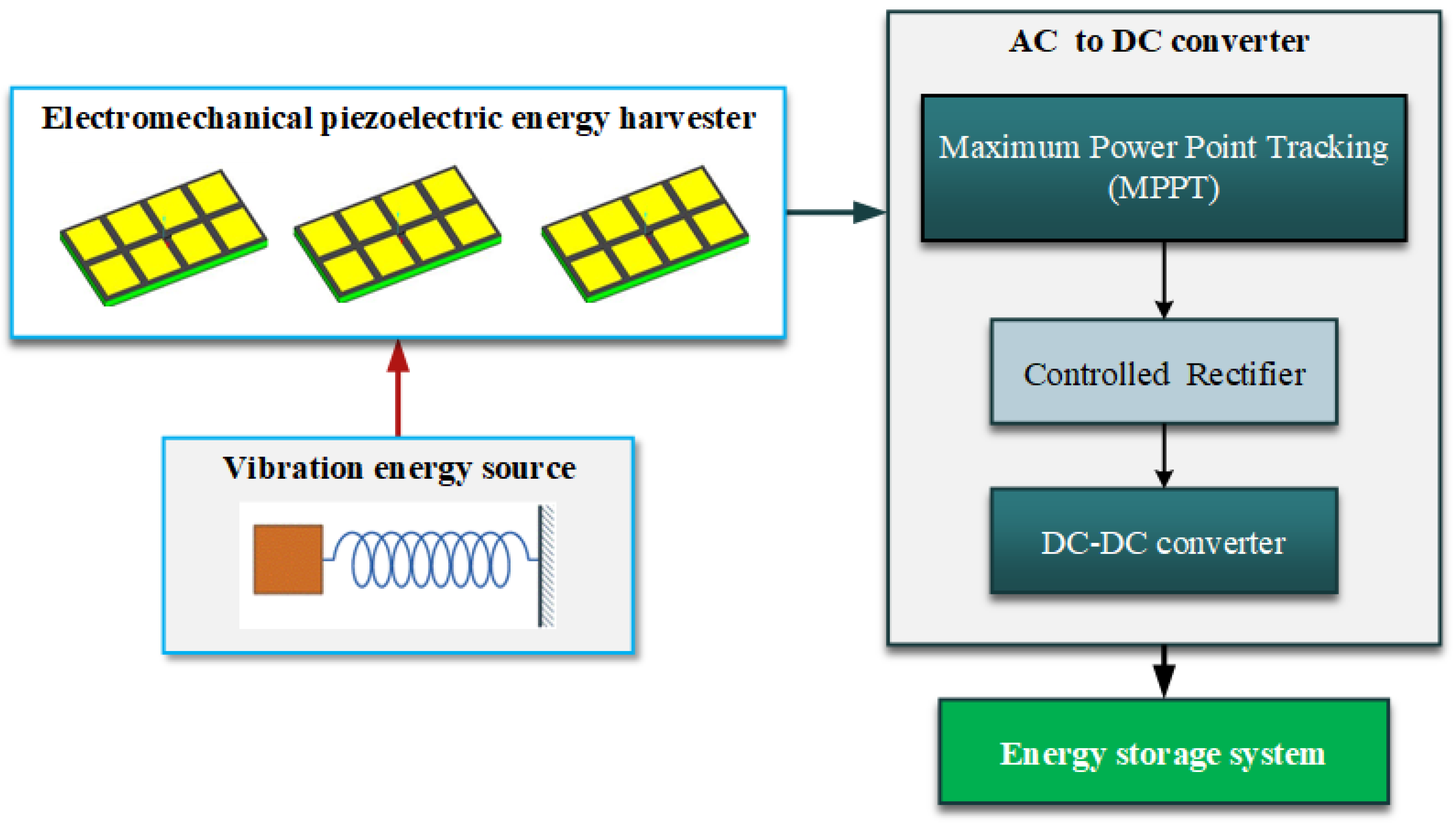
Figure 2.
Essential circuit layout of a single-phase voltage source PWM converter featuring an RC-IGBT.
Figure 2.
Essential circuit layout of a single-phase voltage source PWM converter featuring an RC-IGBT.
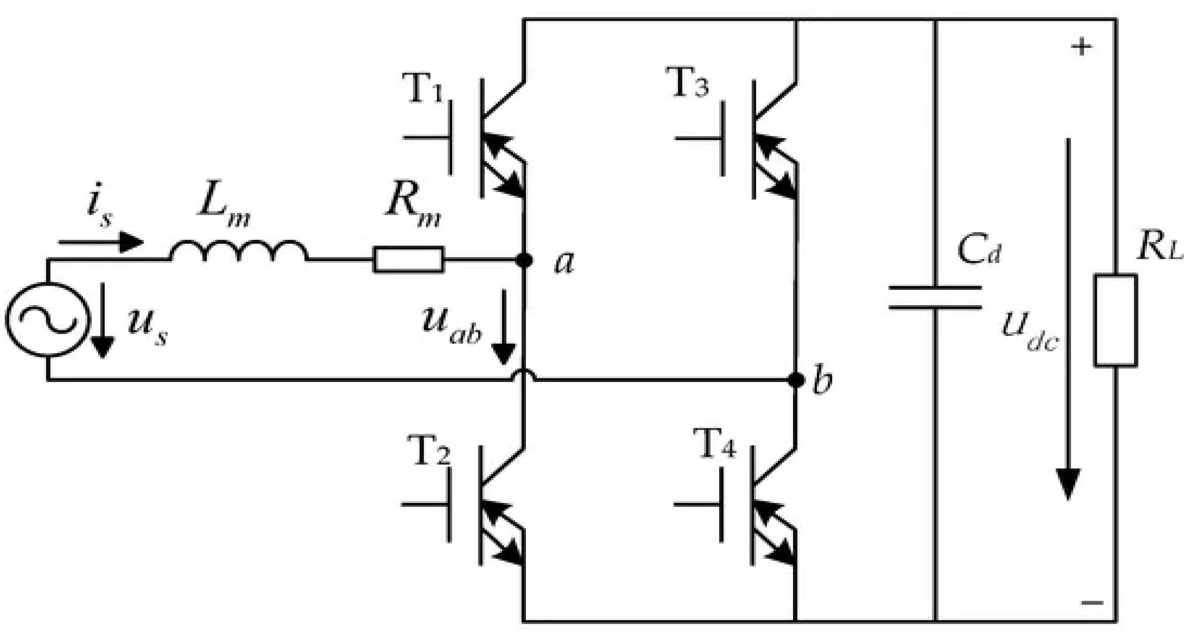
Figure 3.
A traditional buck-boost converter circuit.
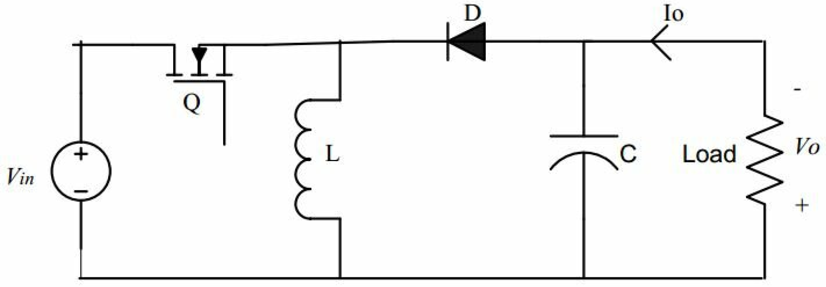
Figure 4.
The flow chart of the Perturb & Observe (P&O) algorithm- MPPT system [24].
Figure 4.
The flow chart of the Perturb & Observe (P&O) algorithm- MPPT system [24].
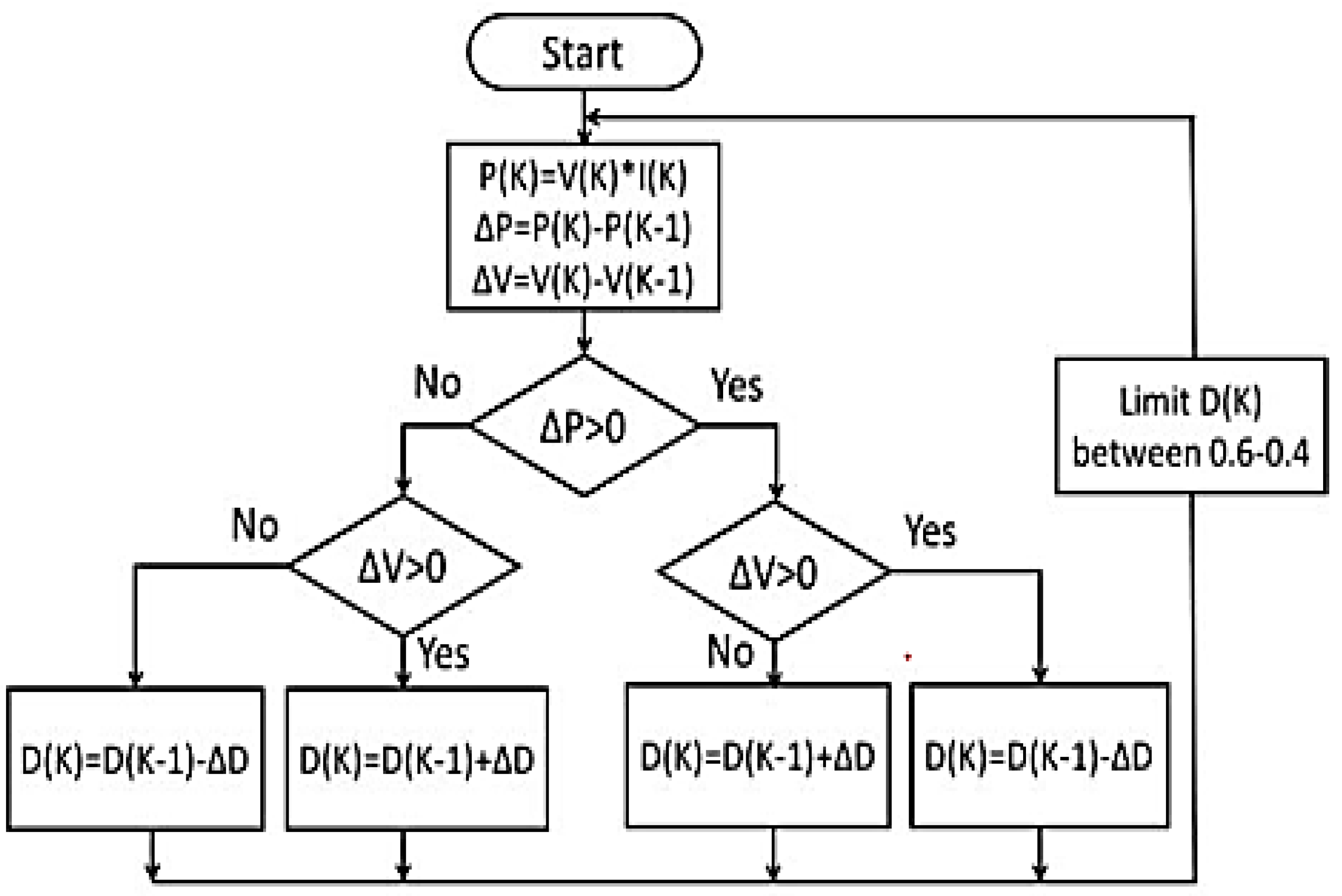
Figure 5.
Implementation of the perturb & observe (P&O) MPPT Algorithm with a closed-loop controller for a DC-to-DC converter.
Figure 5.
Implementation of the perturb & observe (P&O) MPPT Algorithm with a closed-loop controller for a DC-to-DC converter.
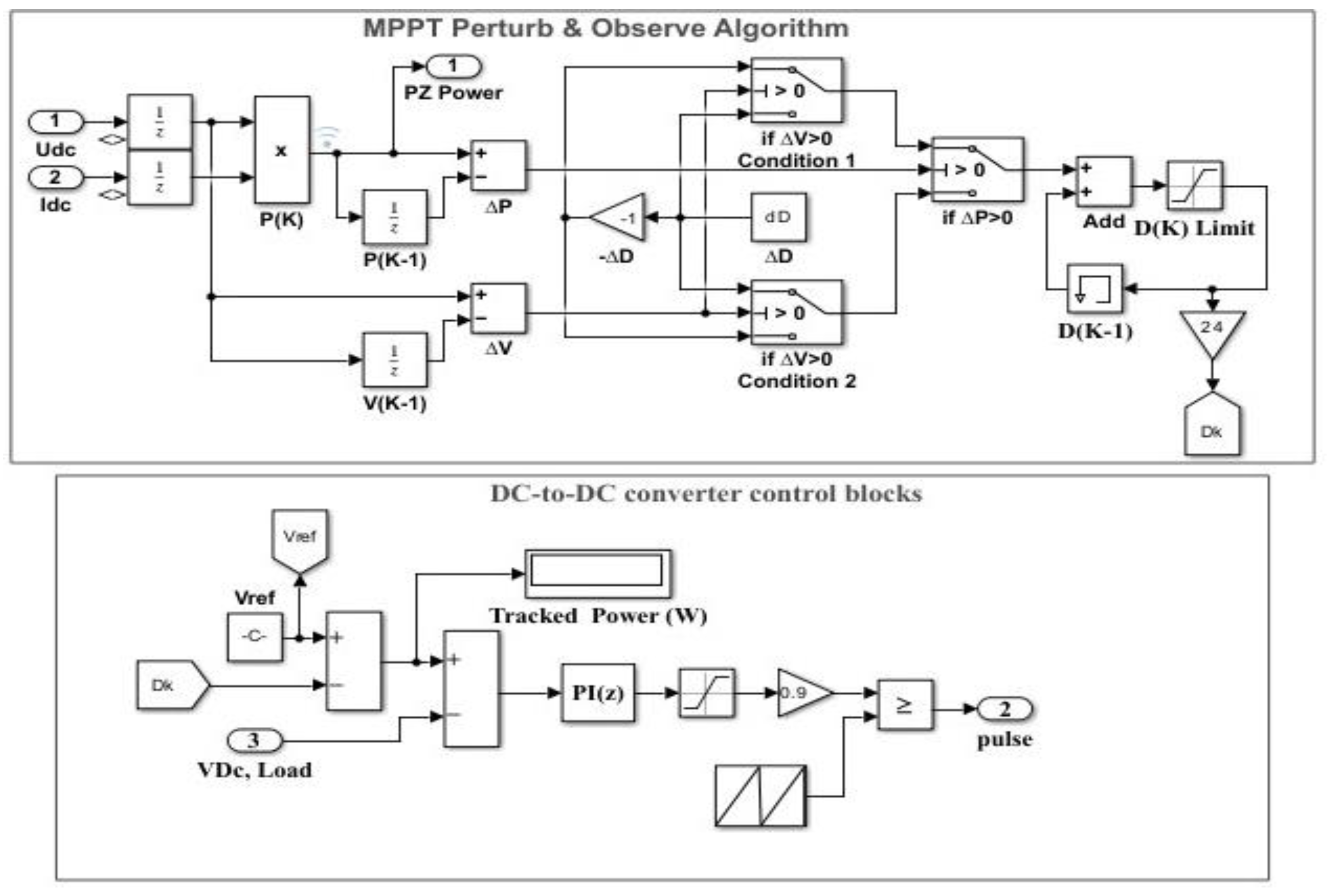
Figure 6.
Piezoelectric wind energy harvesting simulation blocks.
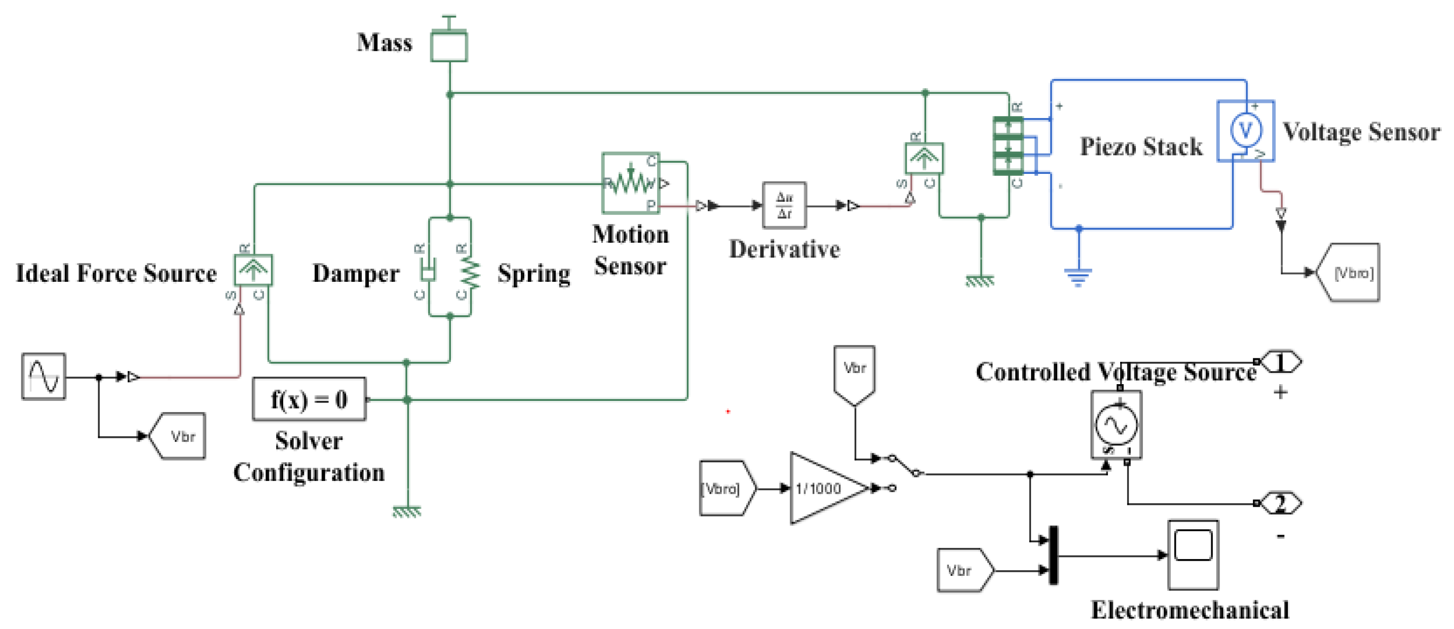
Figure 7.
Simulation blocks of the AC-DC converter.
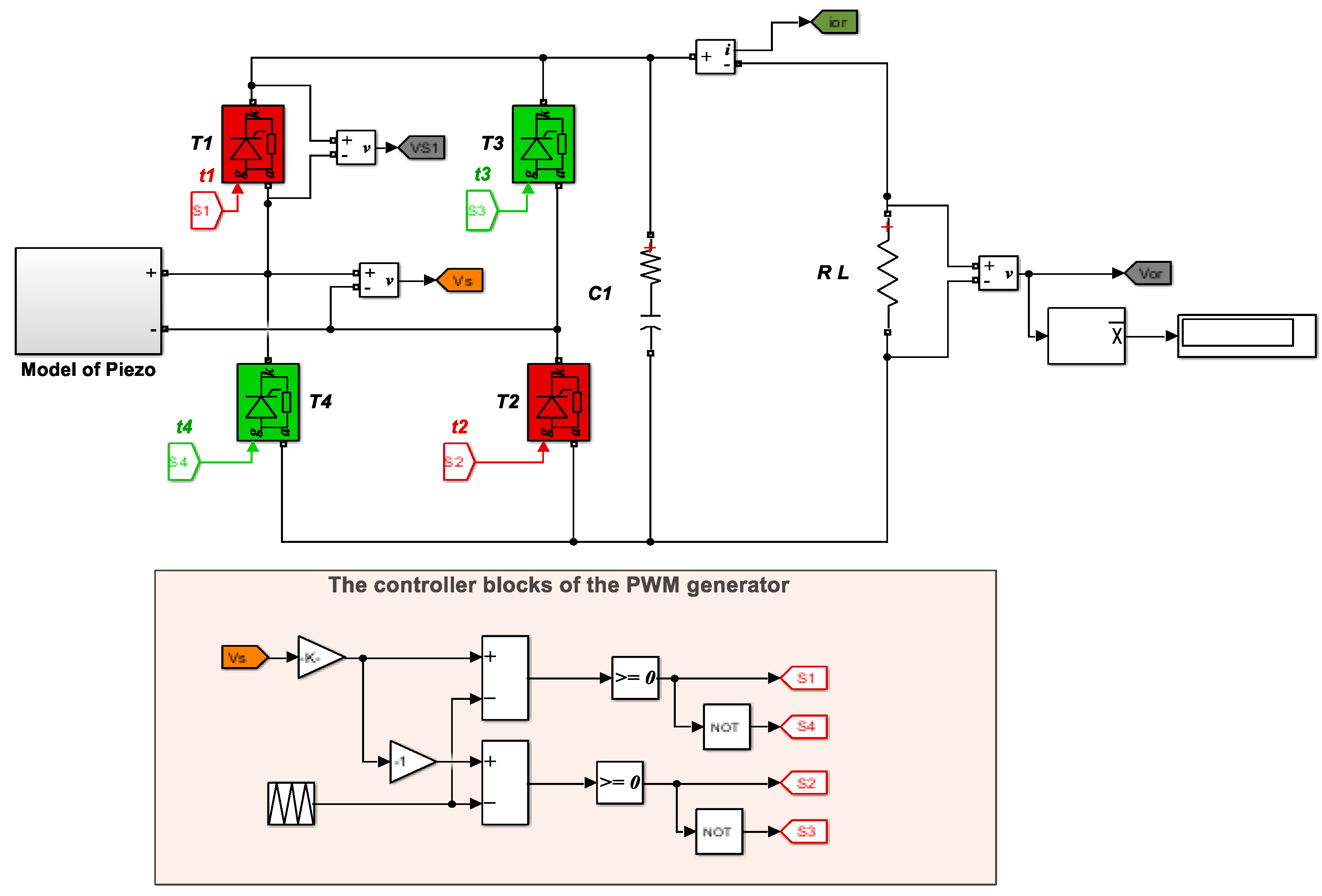
Figure 8.
Closed loop-buck boot converter.
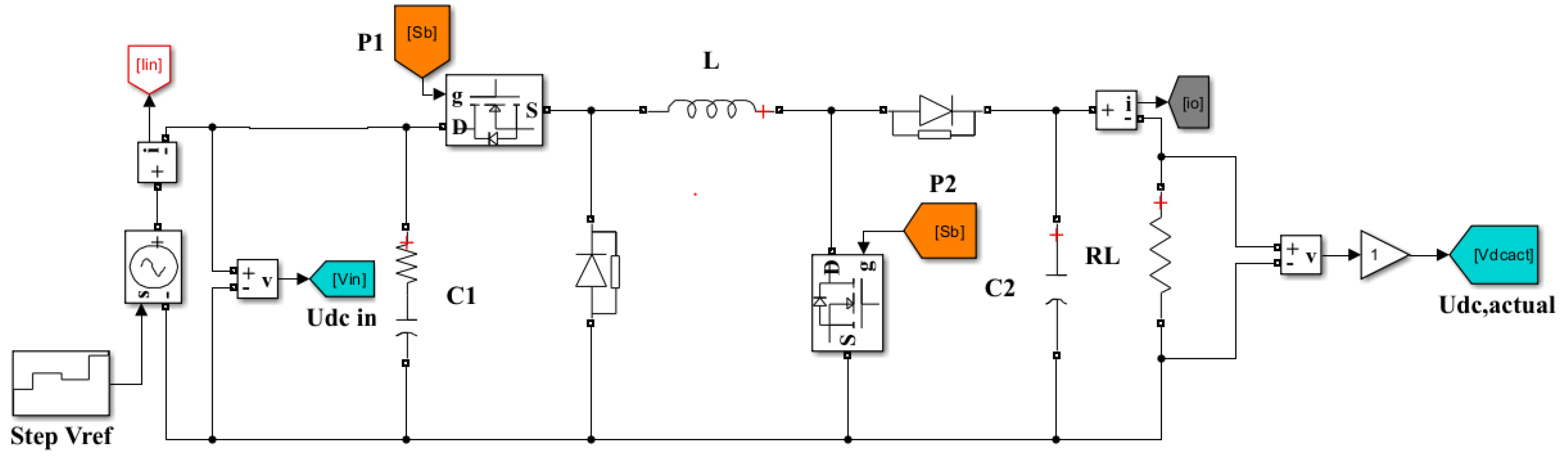
Figure 9.
Rectifier voltage, current, and vibration force at a vibration frequency of 15 Hz.

Figure 10.
Rectifier voltage, current, and vibration force at a vibration frequency of 50 Hz.
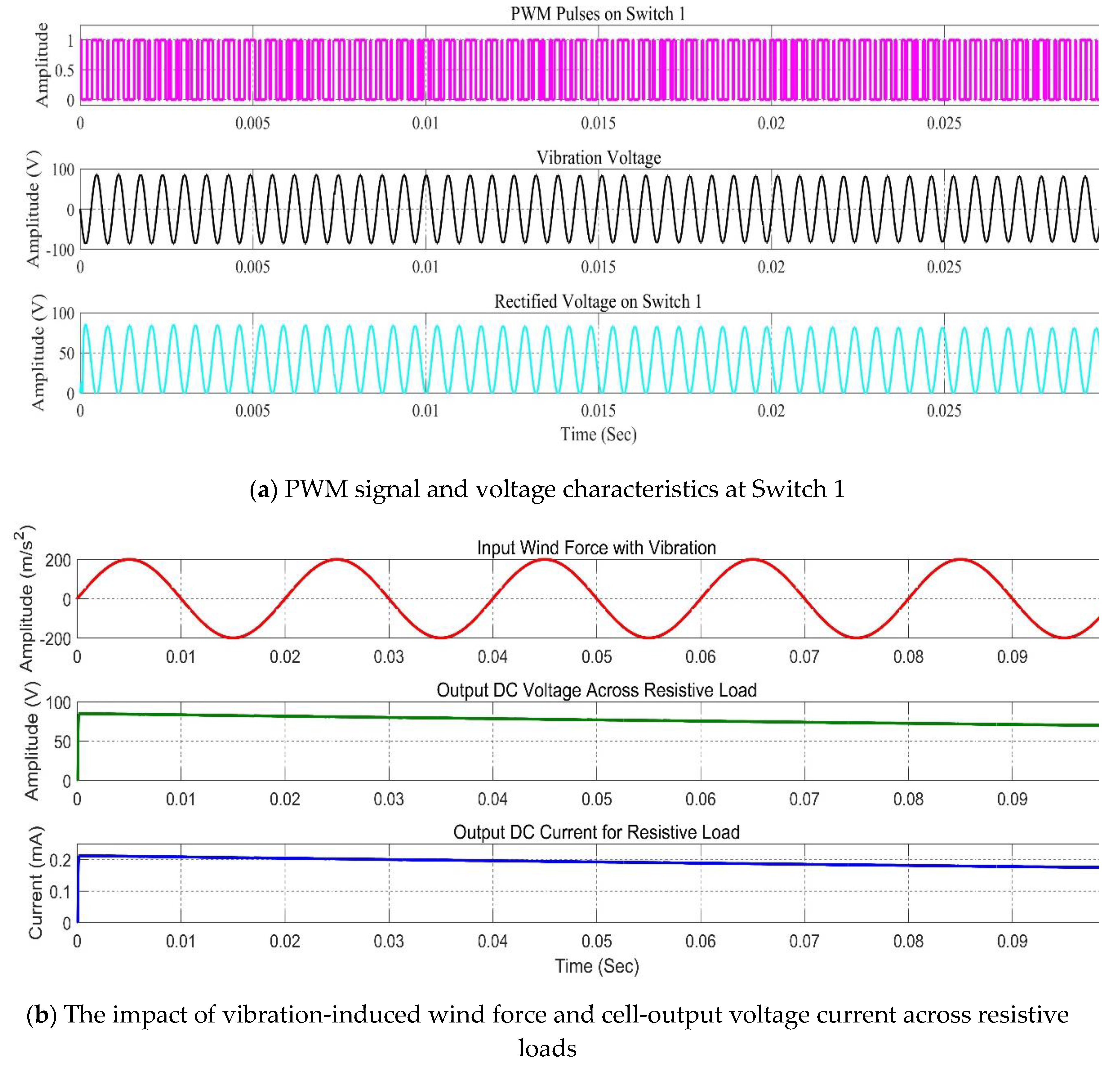
Figure 11.
Rectifier voltage, current, and vibration force at a vibration frequency of 150 Hz.
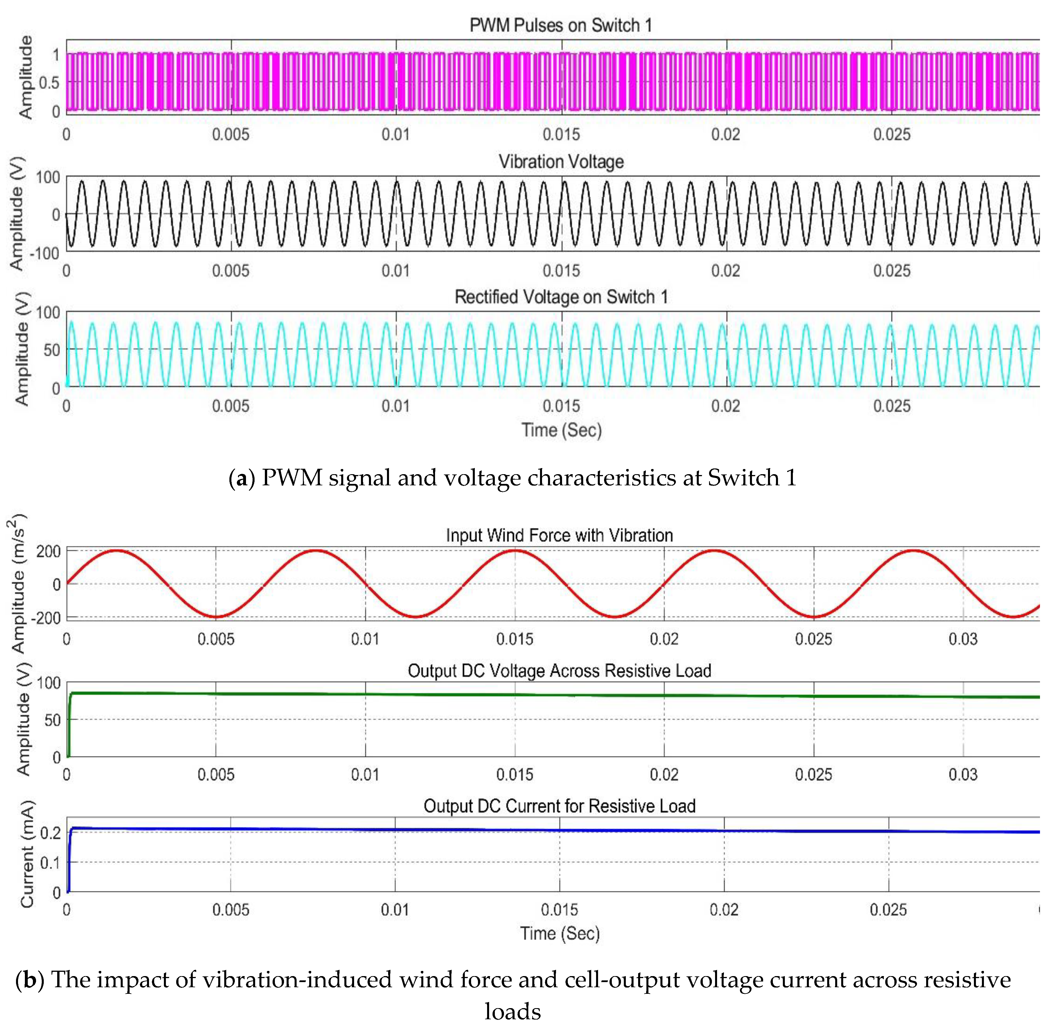
Figure 12.
The performance of the DC-to-DC converter controller on a reference voltage set of 24 V.
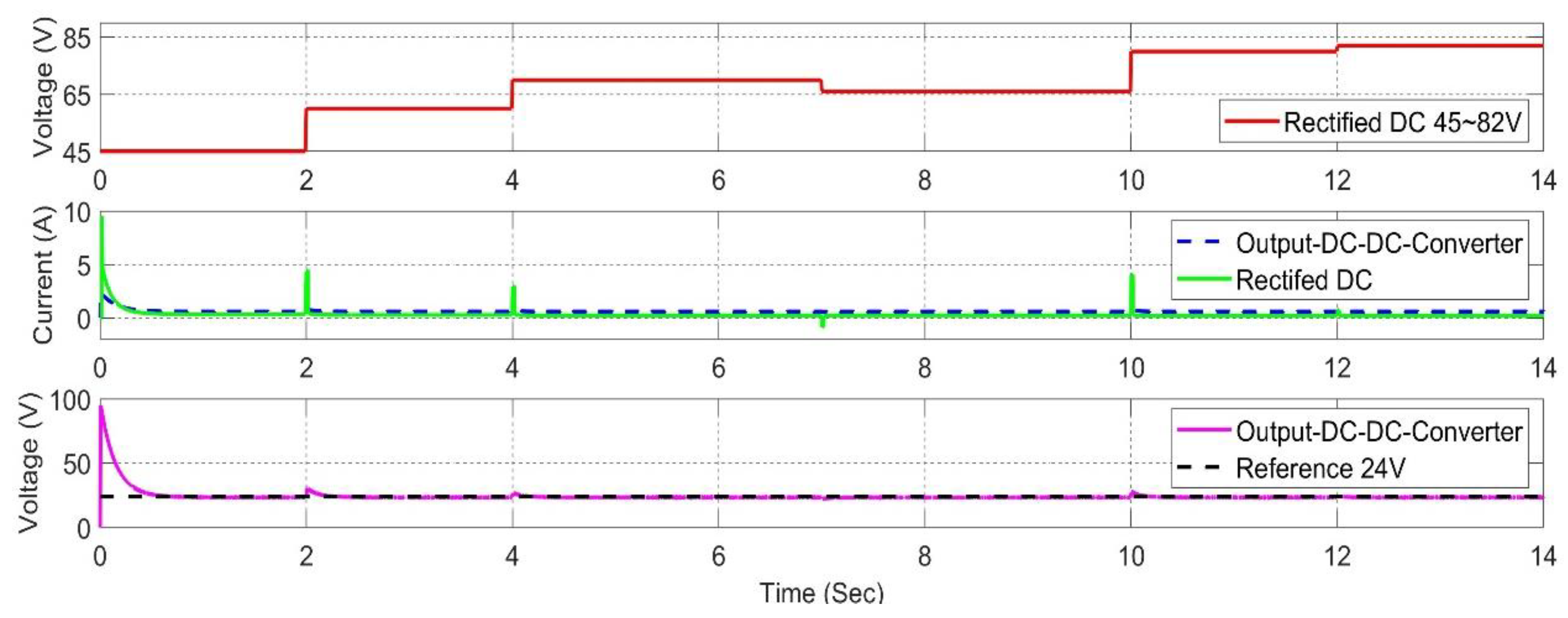
Figure 13.
Wind vibration energy harvester with closed-loop controllers in buck-boost converters (P&O) MPPT.
Figure 13.
Wind vibration energy harvester with closed-loop controllers in buck-boost converters (P&O) MPPT.
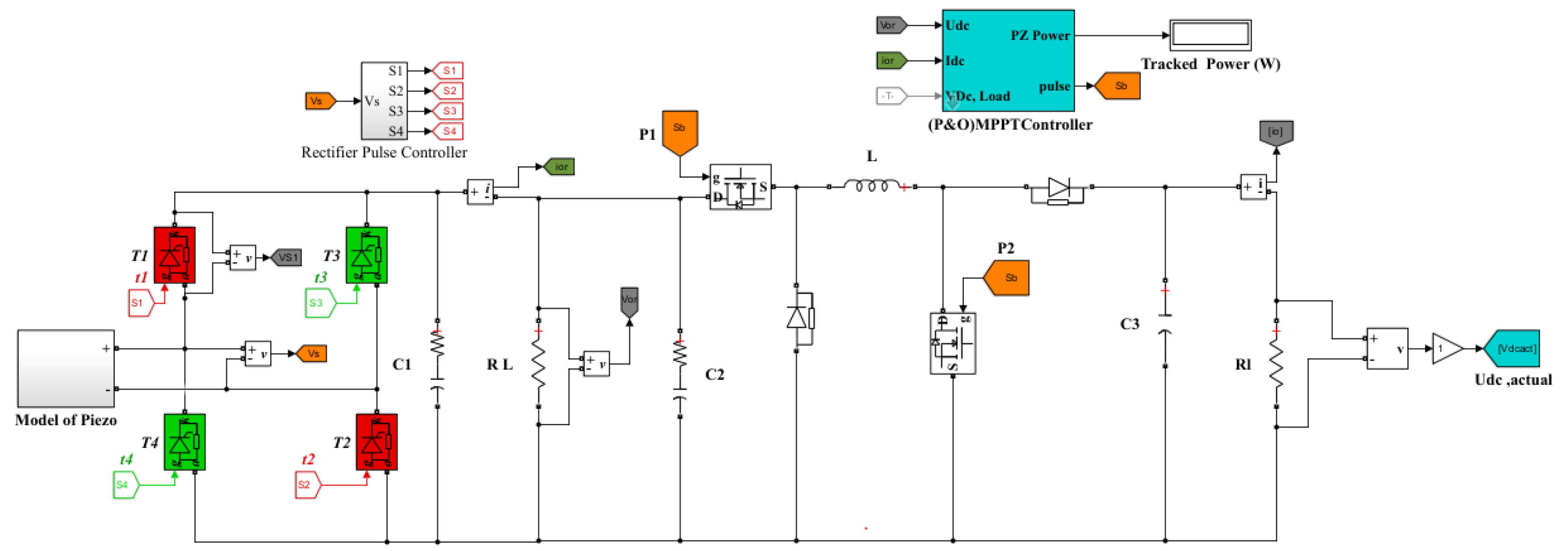
Figure 14.
DC output voltage of PEHS with a closed loop P&O MPPT buck-booster converter.
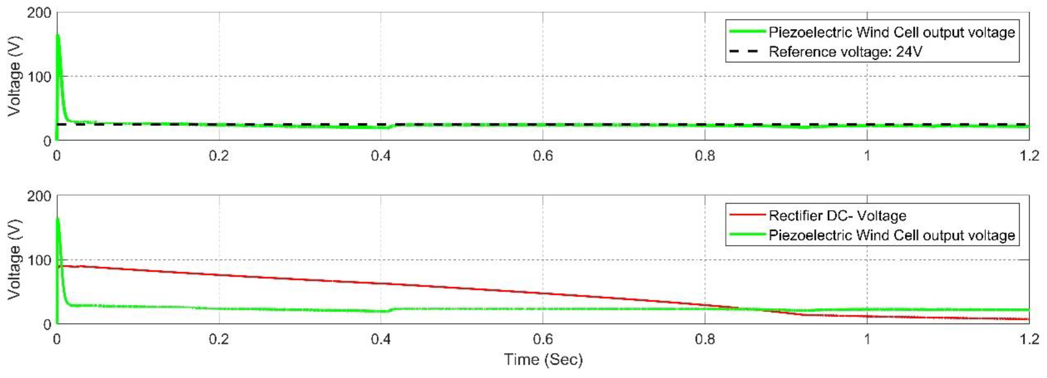

Table 1.
Simulation parameters for the PEHS with vibrational wind force.
| Definition | Value |
|---|---|
| Amplitudes of wind force (N) | 200 |
| Wind vibration speed (Hz) | 50 |
| Translational Damper N(m/s) | 100 |
| Translational Spring (N/m) | 400 |
| Mass for mechanical part (kg) | 3.6 |
| Rectifier Switching Frequency (Hz) | 5000 |
| ) | 4500 |
| DC-Dc-converter Switching Frequency (Hz) | 20000 |
| ) | 45 |
| ) | 100 |
| R-Load (Ω) | 4000 |
Table 2.
Minimum and maximum voltages of an AC‒DC converter with various vibration frequencies.
| ) | Vibration frequency (Hz) | ||
|---|---|---|---|
| 200 | 15 | 75 | 45 |
| 25 | 80 | 58 | |
| 40 | 80 | 66 | |
| 50 | 80 | 70 | |
| 150 | 82 | 80 |
Table 3.
Compared with existing state-of-the-art systems, the vibrational energy harvester system has a closed-loop P&O MPPT DC‒DC converter.
Table 3.
Compared with existing state-of-the-art systems, the vibrational energy harvester system has a closed-loop P&O MPPT DC‒DC converter.
| Refrecne No. | Rectifier structure | DC-DC converter | Simulation design |
Experimental design |
| [19] | Uncontrolled bridge diodes | Not used | Yes | No |
| [26] | Non | Non | Yes | No |
| [18] | Uncontrolled bridge diodes | P&O MPPT Clood-loop boost converter | Yes | Yes |
| Proposed system | PWM Rectifier bridge IGBT | P&O MPPT Clood-loop buck-boost Converter | Yes | No |
Disclaimer/Publisher’s Note: The statements, opinions and data contained in all publications are solely those of the individual author(s) and contributor(s) and not of MDPI and/or the editor(s). MDPI and/or the editor(s) disclaim responsibility for any injury to people or property resulting from any ideas, methods, instructions or products referred to in the content. |
© 2024 by the authors. Licensee MDPI, Basel, Switzerland. This article is an open access article distributed under the terms and conditions of the Creative Commons Attribution (CC BY) license (http://creativecommons.org/licenses/by/4.0/).
Copyright: This open access article is published under a Creative Commons CC BY 4.0 license, which permit the free download, distribution, and reuse, provided that the author and preprint are cited in any reuse.


