Preprint
Article

Oil Distribution around Ball-Raceway Local Contact Region in Under-Race Lubricating Ball Bearing

Altmetrics

Downloads

58

Views

27

Comments

0

A peer-reviewed article of this preprint also exists.

Submitted:

26 August 2024

Posted:

27 August 2024

You are already at the latest version

Alerts
Abstract
The distribution of oil and gas phases around ball-raceway local regions is an important basis and foundation for determining whether a bearing is sufficiently lubricated. To obtain the oil phase distribution law in the inner raceway-ball contact local region (IBCR) and outer raceway-ball contact local region (OBCR) of the under-race lubrication ball bearing, the numerical simulation method is used. The effects of bearing rotation speed, oil flow rate, oil viscosity and oil density on these two regions are studied. The results indicate that the oil phase exhibited significant periodic changes in both time and space. Compared with that in the IBCR, the oil phase distribution in the OBCR is more uniform. Increasing the bearing rotation speed and reducing the oil flow rate made the IBCR and OBCR more uniform. Changing the oil viscosity only alters the distribution pattern of the OBCR. The oil density may not affect the fluid flow state or the oil phase distribution in the bearing.
Keywords: 
Subject: Engineering  -   Mechanical Engineering

1. Introduction

Rolling bearings are widely used in various rotating mechanical systems because of their low friction coefficient and small starting torque. As a supporting rotating component, its working performance has an important influence on the stability and reliability of the whole mechanical system [1]. In the case of high speed and heavy load, an appropriate amount of oil is needed to lubricate and cool the bearing [2]. For high-speed systems such as aeroengines and turbines, jet lubrication is usually used [3]. However, as the bearing speed increases, the internal pressure of the bearing increases, making it difficult for the oil to enter the bearing. Therefore, under-race lubrication is usually used at high speeds [4]. For under-race lubrication high-speed ball bearings, insufficient oil in the bearing will lead to insufficient lubrication of the bearing and cannot take away heat. Excessive oil leads to viscous friction of the fluid [5]. Under certain mechanisms, the percentage of bearing power loss of only the fluid can reach more than 70% [6]. The viscous friction of the fluid in the bearing is related to the oil phase fraction and oil phase distribution in the bearing. In addition, the temperature and heat generation of the components in the bearing are also related to the oil phase distribution in the bearing [7], and the operating parameters of the under-race lubrication ball bearing affect the contact region oil phase fraction and distribution in the bearing [8].
In the under-race lubrication ball bearing, the interaction between the oil and the bearing components results in complex two-phase flow [9], resulting in different oil phase volume fractions and distributions at different positions of the bearing, which affects the heat transfer characteristics of the bearing and has an important influence on the thermal performance of the bearing [10]. Jeng et al. [11] established an oil supply condition measurement device for an oil‒air lubrication system and a high‒speed ball bearing test bench and studied the relationship between the fluctuations in the oil supply fluctuation and the operating parameters of the oil‒air lubrication system. It was found that smaller injection quantities and smaller injection intervals can improve the stability of oil supply. The higher the viscosity of the lubricating oil is, the smaller the fluctuation of oil supply. Flouros [12] studied the two-phase flow in under-race lubrication bearings. The visualization results of the high-speed camera show that the lubricating oil leaves the bearing through the gap between the cage pocket and the outer ring. Jiang et al. [13] established an oil‒air lubrication experimental device for high-speed ball bearings and experimentally researched the performance of ceramic and steel ball bearings under various working conditions. For each speed, there is an appropriate amount of lubricant to maintain a low temperature increase, and the appropriate amount of lubricant increases with increasing speed. Zeng et al. [14] obtained the flow pattern inside a bearing under different working conditions through numerical simulations and experiments. They reported that structural parameters such as the inclination angle and pipe diameter strongly influence the distribution of oil‒gas two-phase flow. Wu et al. [15] studied stratified gas‒oil flow inside a jet-cooled ball bearing. The temperature distribution of the bearing is affected by the volume fraction distribution. The traditional oil injection lubrication mechanism cannot effectively cool the inner ring of a high-speed ball bearing. Yan et al. [16] discussed the oil and gas flow and lubrication performance of two kinds of ball-bearing lubrication devices and studied and improved their key structural parameters. Finally, the optimal oil supply parameters and operating performance of the two devices were obtained through experimental tests. Bao et al. [17] used the CFD method to simulate the oil‒air two-phase flow inside a under-race lubrication ball bearing. As the speed increases, the oil phase volume fraction gradually decreases. Owing to the centrifugal force, the lubricating oil is concentrated mainly on the outer ring raceway, which is beneficial for lubrication and cooling of the outer ring. Peterson et al. [18] established a CFD model of ball bearings and studied the effects of the inner ring speed, fluid viscosity, number of rolling elements, and cage on the internal flow of bearings. Liu et al. [19] established a fluid‒solid coupling simulation model based on the CFD method to investigate the lubrication characteristics of oil jet lubrication ball bearings in a gearbox. During the lubrication process, the distribution of oil inside the bearing is not uniform. The minimum oil volume fraction is observed near the upstream of the nozzle in the direction of bearing rotation. The average oil volume fraction and oil passing rate decrease with increasing bearing speed and viscosity. Zhang et al. [20] used the CFD method to simulate the transient flow of oil and gas two-phase flow in a jet lubrication roller-sliding bearing. The oil distribution in the bearing is uneven, and it gradually increases from the inner raceway to the outer raceway. Shan et al. [21] proposed a general method for establishing a lubrication analysis model of ball bearings, analyzed the variation in hydrodynamic characteristics such as oil and gas distribution, temperature and flow rate under different lubrication conditions, and reported that an appropriate gap size can improve the internal flow pattern and hydrodynamic performance of ball bearings.
In summary, the current research on the oil‒phase two‒phase flow and distribution in bearings has focused mainly on jet lubrication, but research on the oil‒gas two‒phase distribution in the under-race lubrication ball bearings is relatively lacking, and an understanding of the oil‒gas two‒phase distribution in the ball‒raceway local region of bearings is lacking. It is difficult to carry out a more refined design of the bearing. The distribution of the oil and gas phases around the ball-raceway local region is an important basis and foundation for determining whether the bearing is sufficiently lubricated. Therefore, it is necessary to study the local distribution and variation in the oil and gas phases in the contact region of the bearing ball under different conditions. Because it is difficult to obtain the oil‒gas two‒phase flow and distribution in high‒speed ball bearings via theory and experiments, the oil‒gas two‒phase distribution in the ball‒raceway local region of the under-race lubrication ball bearing is studied via numerical simulation.

2. Model and Method

2.1. Geometric Model

A three-dimensional schematic diagram of the under-race lubrication ball bearing, including the inner ring, outer ring, cage and balls, is shown in Figure 1. There are 6 oil supply holes evenly arranged on the inner ring along the circumference, and the lubricating oil flows into the bearing along the oil supply hole through the rotating centrifugal force of the inner ring. After lubrication and cooling in the bearing, the oil flows out of the bearing through the gap between the inner ring and the outer ring of the bearing. The geometric parameters of the ball bearing are shown in Table 1. To simplify the calculation, the contact gap between the inner and outer raceways of the bearing and the ball is larger than the actual structure.

2.2. Computational Domain and Mesh

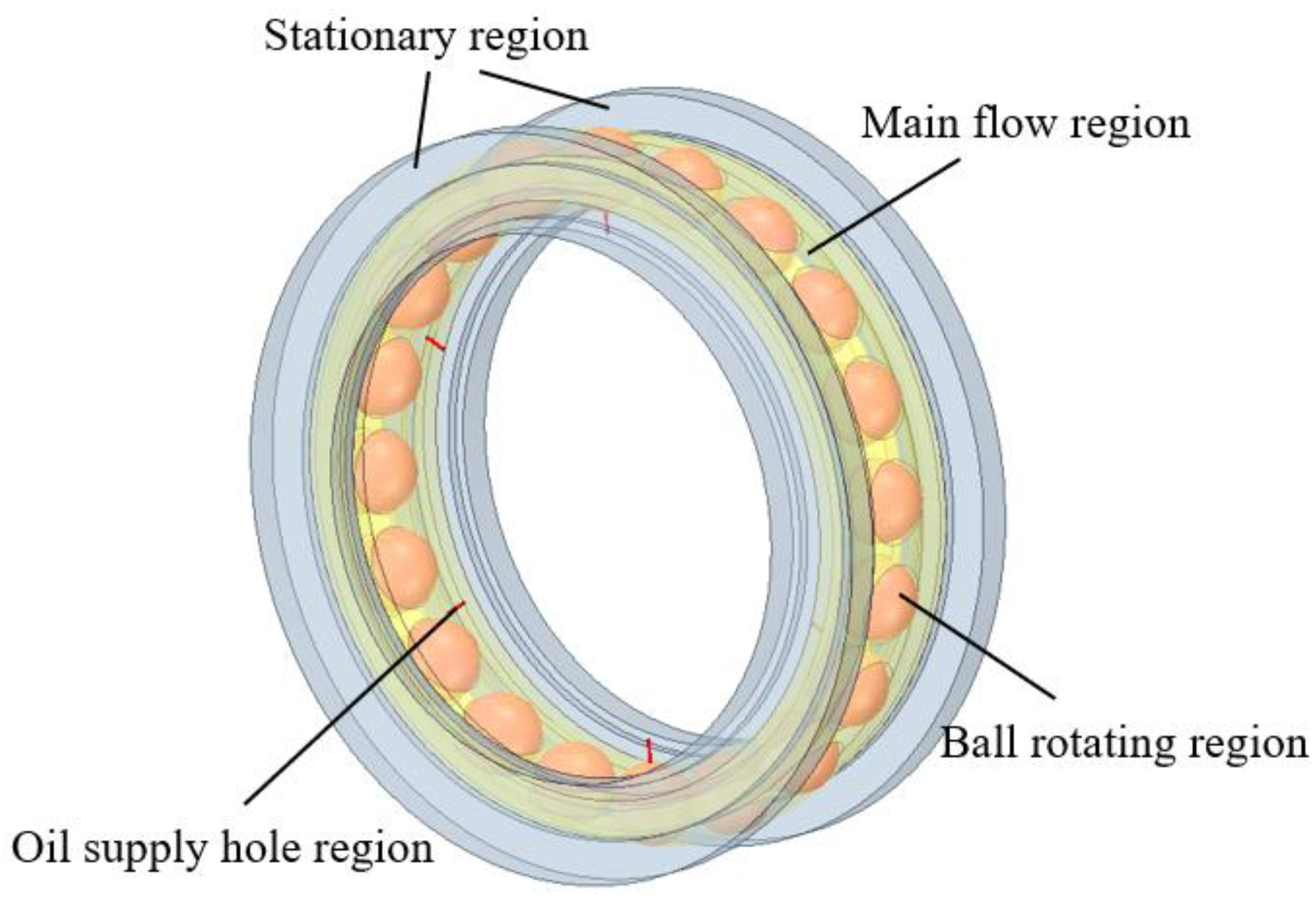
This study focuses only on the inside of the ball bearing, so only the fluid domain of the bearing is retained, and the solid structure of the bearing is discharged. The calculational domain is shown in Figure 2. Because the movement of each part in the bearing is different, the fluid domain is divided into the main flow region, the ball rotation region, the oil supply hole region and the stationary region. The oil supply hole is located on the inner ring of the bearing and rotates around the bearing center with the rotation speed of the inner ring, so the rotation speed of the oil supply hole region is the same as that of the inner ring. The rotation speed of the main flow region inside the bearing is the rotation speed of the cage, and the rotation speed of the cage is:
n m = n i 2 ( 1 D cos α d m )
The ball rotates around its own axis while rotating around the center of the bearing. The speed of the ball revolution is the same as the speed of the cage, and the self-rotation speed of the balls is [8]:
n r = d m n i 2 D [ 1 ( D cos α d m ) 2 ]
where nm is the cage speed; ni is the inner ring speed; D is the diameter of the ball; α is the contact angle; dm is the pitch diameter; and nr is the ball’s self-rotation speed.
On the one hand, the stationary region on both sides of the bearing provides a reasonable bearing chamber environment for the bearing; on the other hand, it reduces the influence of the reversed flow phenomenon on the calculation results in the numerical calculation.
Owing to the complex structure of the ball bearing, an unstructured tetrahedral mesh is used to discretize the internal flow field of the bearing, and a structural hexahedral mesh is used to discretize the oil supply hole region. The contact region between the ball and the raceway in the fluid domain and the oil supply hole region are meshed finely to ensure high mesh quality, as shown in Figure 3. To ensure the validity of the numerical results, a grid independence test of the numerical solution is carried out, as shown in Table 2. The results show that increasing the grid density has little effect on the calculation results. Considering the computational cost, the number of cells in the whole computational domain is 3563698, and the number of nodes is 615636.
The 6 oil supply holes under the inner ring are set as the velocity inlet of the calculation domain, the two end faces of the stationary region are set as the pressure outlet, and the reference pressure is the standard atmospheric pressure. Considering the relative rotational motion between different regions in the bearing, they are related to each other to complete the data transmission. The standard wall function is used near the wall, and the other walls have nonslip boundary conditions.

2.3. Two-Phase Flow Model

Since the fluid domain in the ball bearing involves oil‒gas two-phase flow, the multiphase flow VOF method is used to track the oil‒gas two-phase flow. The VOF model uses the volume fraction function to represent the position of the free surface of different fluids and the volume occupied by different fluids, which can better capture the interface of different phases [22]. When φoil is used to represent the volume fraction of the oil phase, the following three cases may exist in any given cell:
  • When φoil = 0, the cell is empty of the oil.
  • When φoil = 1, the cell is full of oil.
  • When 0<φoil<1, the cell contains the interface between the oil and air.

2.4. Numerical Method

There is a large velocity difference between the parts of the ball bearing at high speed, so a complex turbulent flow will be formed in the bearing. Considering the influence of the high strain rate and large curvature overflow of the bearing and that RNG κ--ε can improve the accuracy under rotating flow, the RNG κ--ε turbulence model is adopted [23].
In the numerical calculation, the sliding mesh method is used to simulate the motion of each region in the bearing. During initialization, the volume fraction of the gas phase in the whole calculation domain is set to 1, and the volume fraction of the oil phase is set to 0. Air is set as the incompressible main phase, and oil is set as the secondary phase. The SIMPLE algorithm is used to couple the pressure and velocity of the two-phase flow in the ball bearing, and the pressure term is PRESTO! The momentum, turbulent kinetic energy and turbulent dissipation are discretized by the upwind scheme. The convergence of the calculation is judged by the flow difference between the inlet and outlet. When the flow difference between the inlet and outlet is within 3%, the calculation is regarded as convergence, the calculation is stopped, and the calculation results are viewed.

3. Results and Discussion

3.1. Two-Phase Characteristics of Oil and Gas in the Contact Region of a Ball Bearing

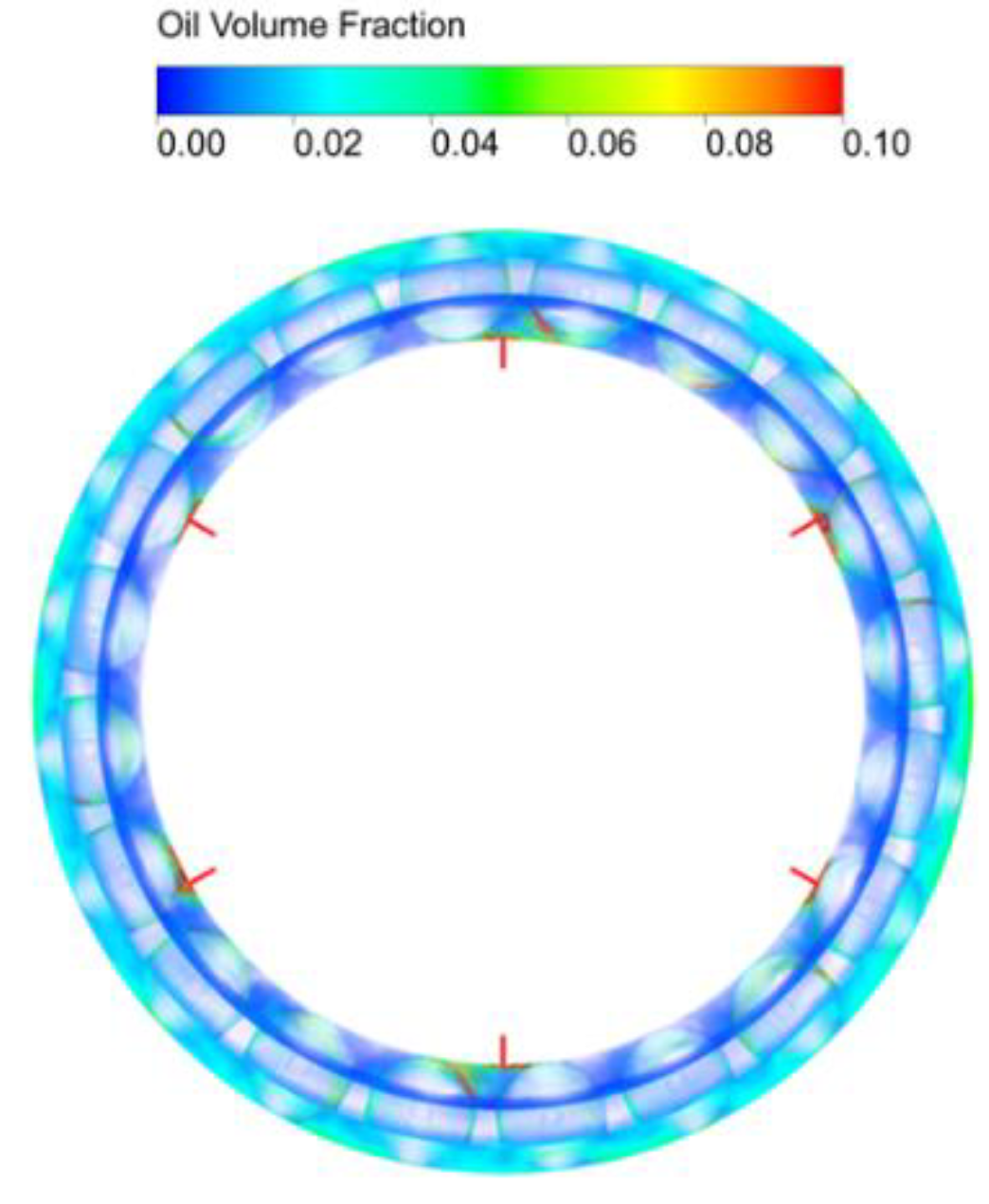
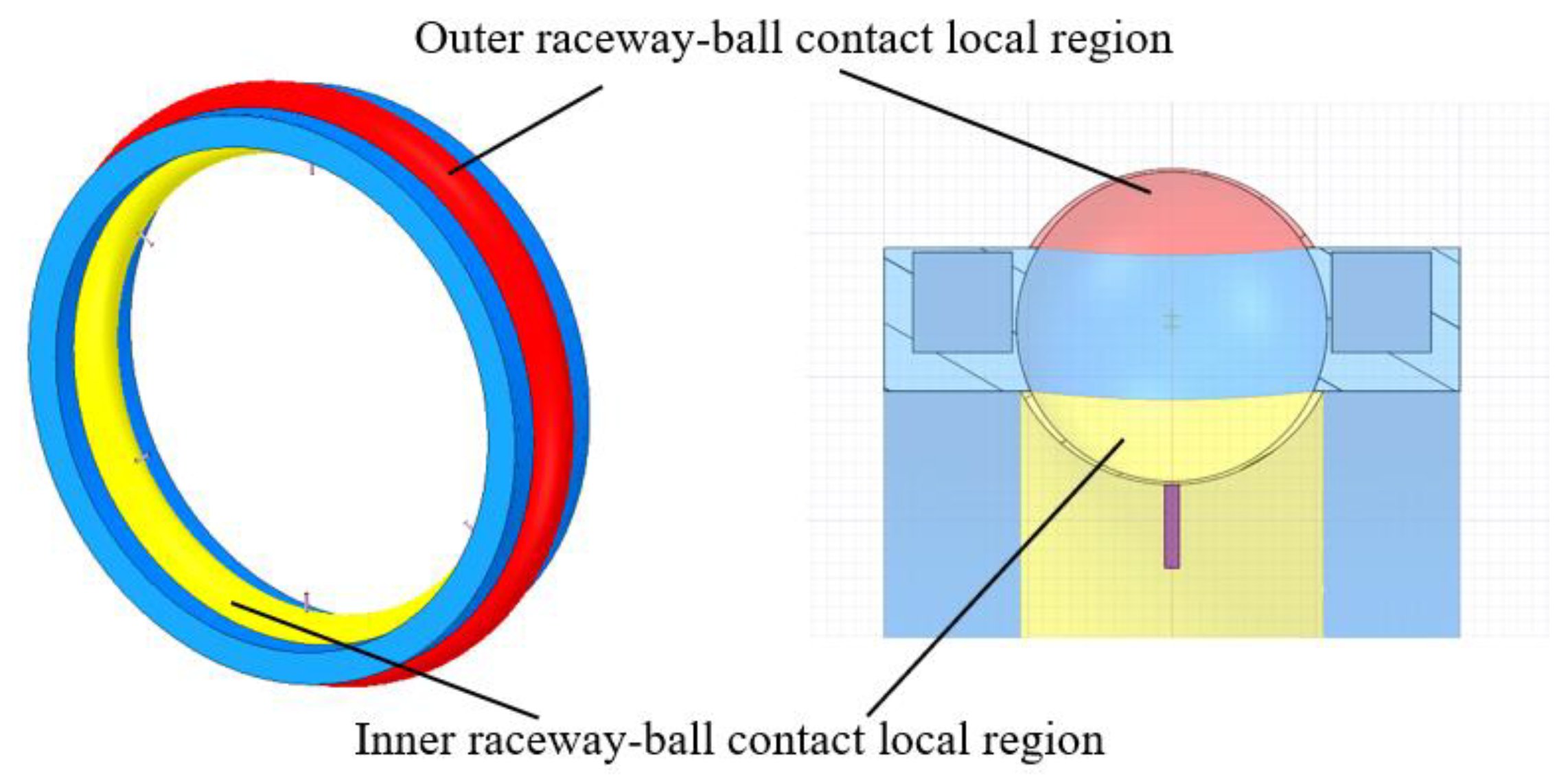
Figure 4 shows the oil‒gas two-phase distribution in the bearing cavity. The bearing rotation speed is 11000 rpm, the oil flow rate is 4 L/min, the oil viscosity is 0.0046 Pa·s, and the oil density is 938.6 kg/m3. After the oil flows out of the oil supply hole, due to the centrifugal force, the oil flows from the inner circulation to the cage pocket and finally flows through the cage pocket to the outer ring region of the bearing. In addition, the oil is unevenly distributed in the bearing. There is more oil near the oil supply hole and less oil away from the oil supply hole. To explore the contact region oil‒gas two-phase distribution characteristics in the under-race lubrication ball bearing, the ball bearing is divided into two regions along the radial direction: the inner raceway‒ball contact local region (IBCR) and the outer raceway‒ball contact local region (OBCR), as shown in Figure 5.
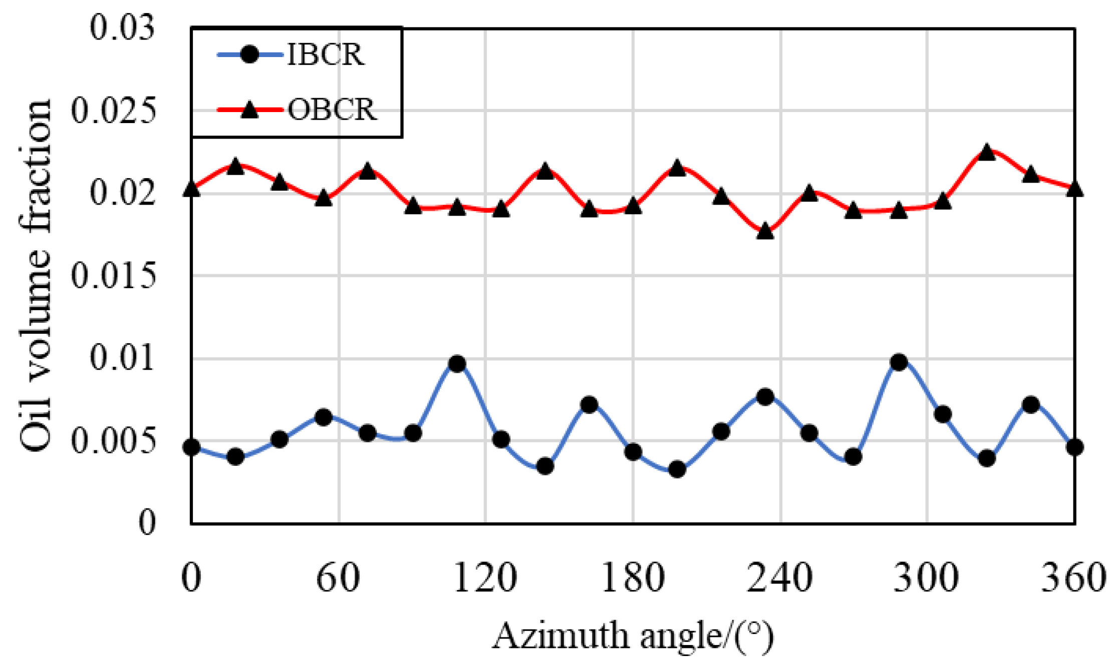
As shown in Figure 6, the oil-phase volume fractions of these two regions along the circumferential direction simultaneously exhibit the largest fluctuation in the IBCR, followed by the OBCR. The oil volume fraction of the OBCR is greater than that of the IBCR; therefore, the lubricating and cooling conditions of the outer raceway-ball contact are better than those of the inner raceway. There are 6 peaks in the circumferential volume fraction of both the IBCR and OBCR samples, which is consistent with the number of oil supply holes.

3.2. Effect of the Rotating Speed of the Bearing

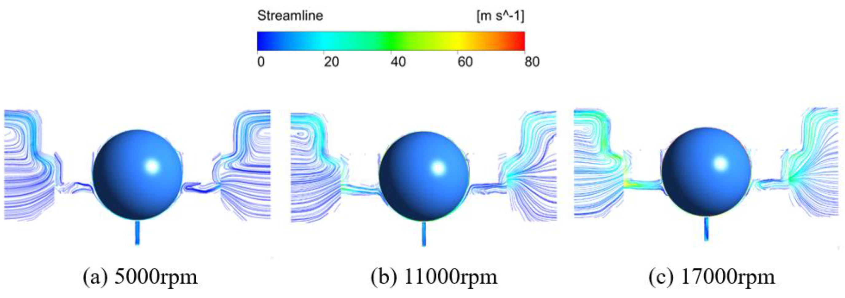
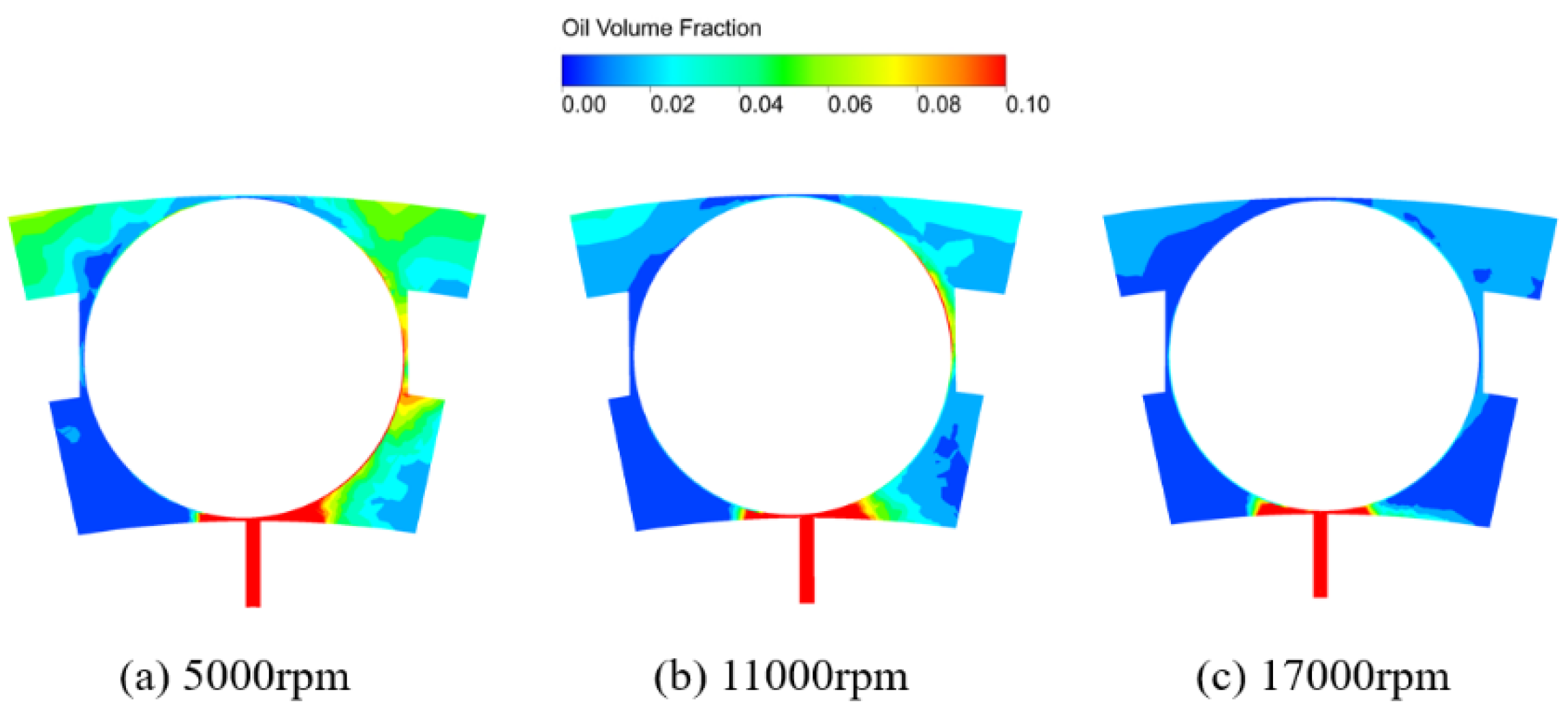
As shown in Figure 7, the streamlines around the ball at different bearing rotating speeds are displayed. When the oil enters the bearing through the oil supply hole, a portion of the oil flows out of the bearing through the gap between the inner ring and the cage, whereas another portion of the oil passes through the gap between the bearing and the cage to reach the outer ring region of the bearing and finally flows out of the bearing through the gap between the cage and the outer ring. Figure 8 shows the distribution of the oil and gas phases around the ball. After entering the bearing through the oil supply hole, the lubricant oil passes through the gap between the ball and the cage to reach the outer ring region and finally accumulates in the outer ring. As the bearing rotation speed increases, the amount of oil in various regions of the bearing increases.
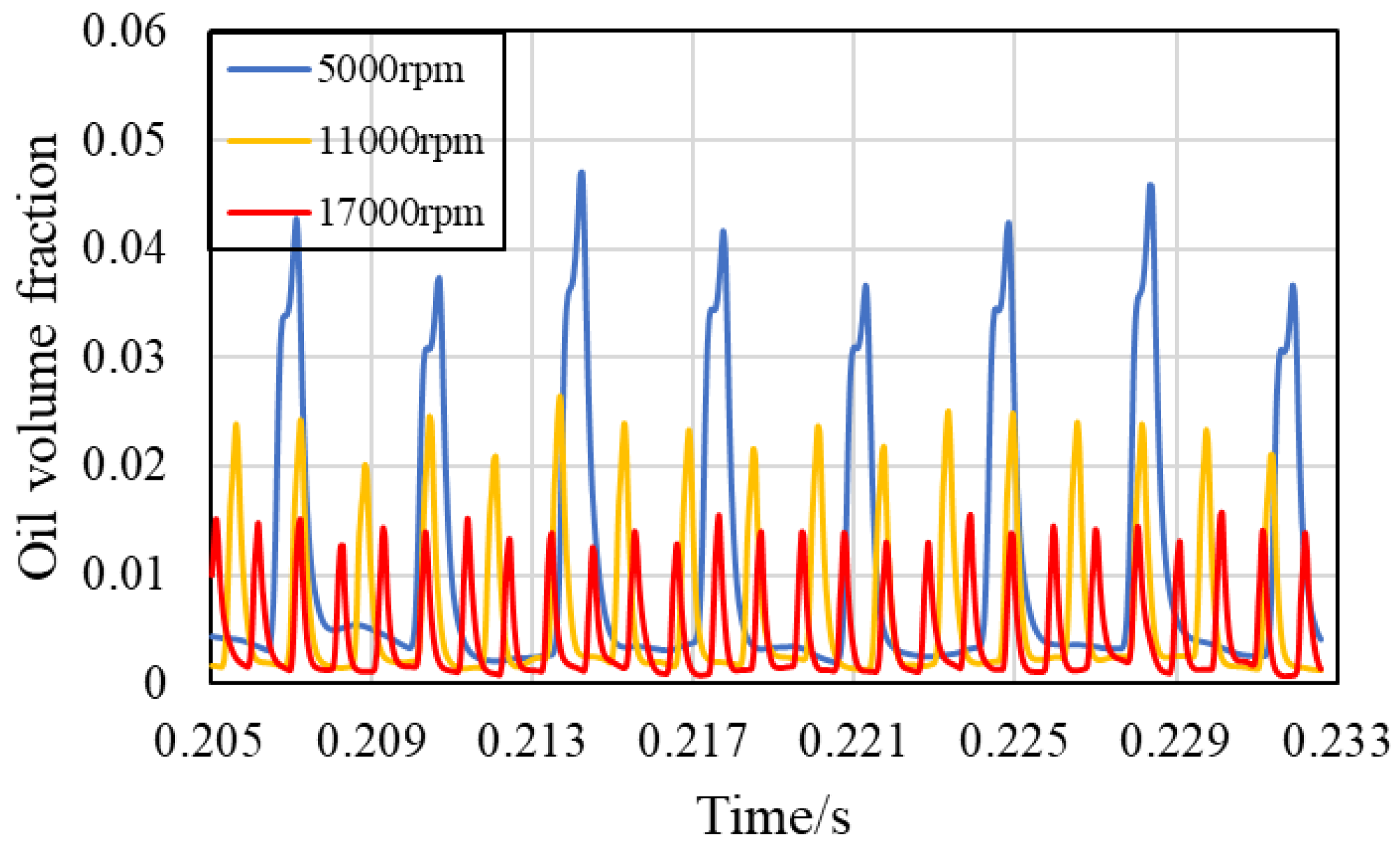
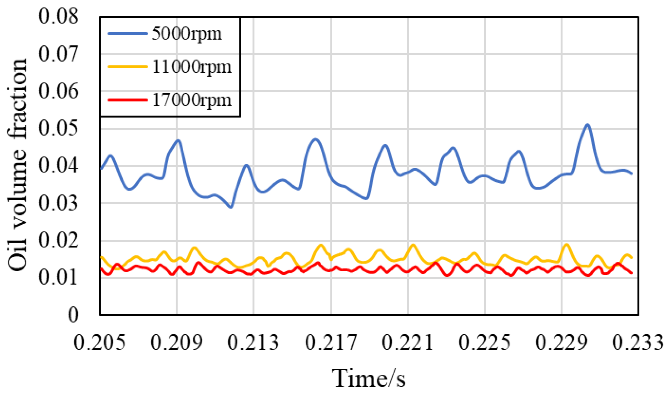
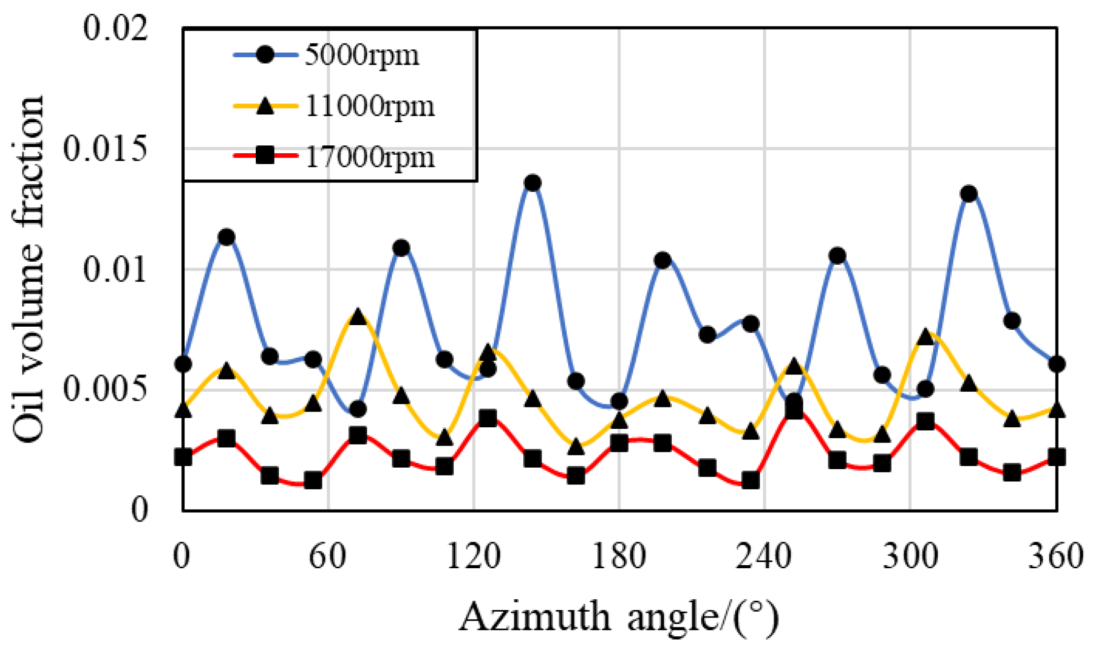
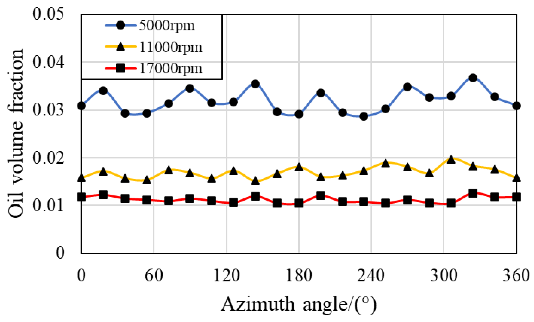
When the bearing rotation speed is 5000 rpm, the volume fraction of the oil phase in the IBCR and OBCR changes over time after one revolution of the bearing, as shown in Figure 9 and Figure 10. The oil clearly has a periodic pattern in the IBCR, and the oil phase increases significantly near the oil supply hole in the OBCR. There is also a periodic pattern in the OBCR, but the fluctuation of the oil phase in the IBCR is greater, and the oil phase distribution in the OBCR is more uniform. Owing to the influence of the centrifugal force of the bearing rotation, the volume fraction of the oil phase in the OBCR is greater than that in the IBCR. As the bearing rotation speed increases, the volume fraction of the oil phase becomes more uniform in both regions, but the volume fraction of the oil phase decreases. Through analysis, the variation in the oil phase volume fraction in the bearing over time can be calculated according to the following formula:
N = n i n m n m A
Where N is the number of peak values, nm is the cage speed, ni is the inner ring speed, and A is the number of fuel supply holes.
When the bearing rotation speed is 5000 rpm, there are 7.8 peaks, whereas the peaks at 11000 rpm and 17000 rpm are 2.2 times and 3.4 times greater than those at 5000 rpm, respectively. Therefore, when the bearing rotation speed is 11000 rpm, there are 17.2 peaks, and when the bearing rotation speed is 17000 rpm, there are 26.5 peaks, which is consistent with the results shown in Figure 9 and Figure 10.
Figure 11 shows the volume fraction of the IBCR along the circumferential direction at different bearing rotating speeds. The bearing inner ring region clearly shows a periodic change law, which is related to the number of oil supply holes. There is more oil near the oil supply hole and less oil away from the oil supply hole. Figure 12 shows the volume fraction of the oil phase along the circumferential direction of the OBCR at different bearing rotating speeds. When the bearing rotation speed is 5000 rpm, the periodicity of the outer ring region is more obvious, and when the bearing rotation speed is 17000 rpm, the periodicity of the outer ring region is not obvious. These two regions in the bearing exhibit a periodic distribution along the circumferential direction at different bearing rotating speeds, and the peak value of the circumferential distribution is consistent with the number of oil supply holes. As the bearing rotation speed increases, the volume fraction of the oil phase in the bearing decreases, and the oil in each region inside the bearing tends to be uniform along the circumferential direction. Through analysis, it can be concluded that the spatial distribution pattern is consistent with the temporal variation pattern. Therefore, in the following analysis, only the spatial distribution pattern is studied.

3.3. Effect of the Oil Flow Rate

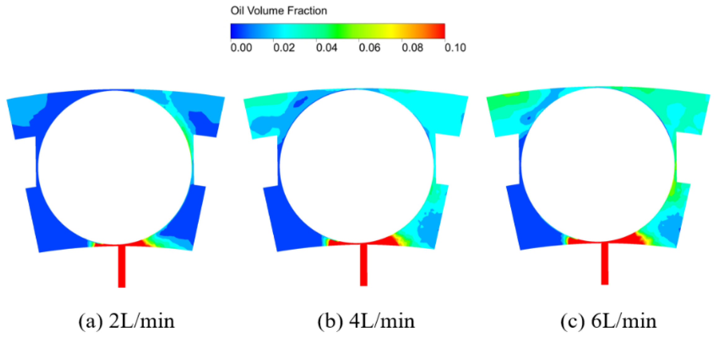
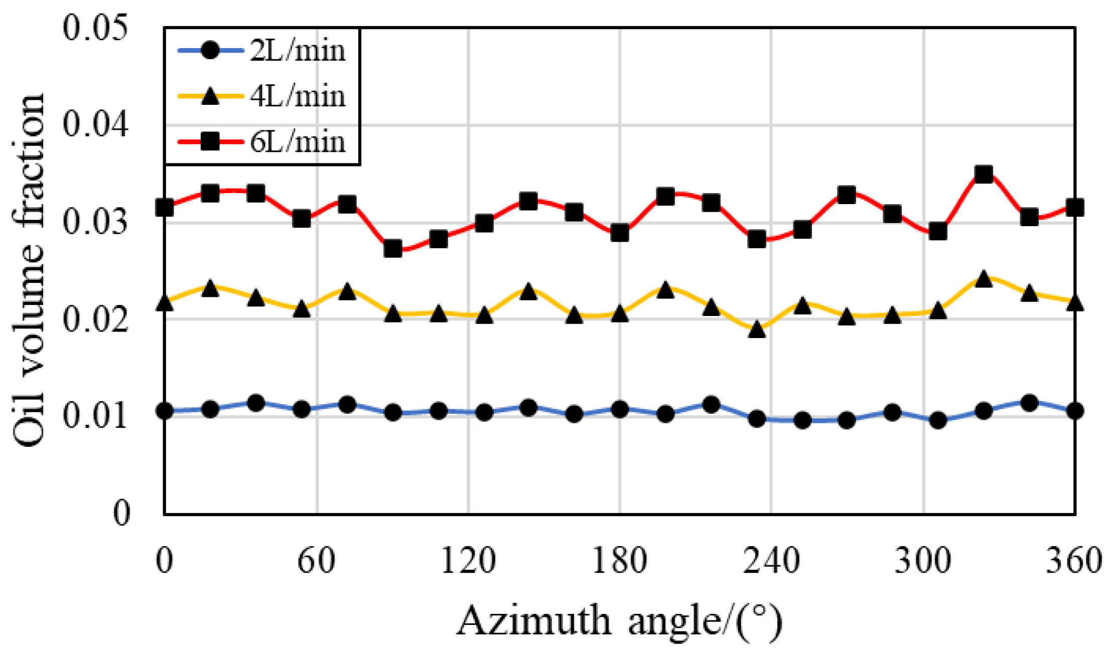
Figure 13 shows the streamlines at different flow rates. When the oil flow rate changes, the bearing rotation speed remains unchanged, and the relative motion of various components inside the bearing also remains unchanged. Therefore, the fluid velocity inside the bearing remains essentially unchanged. As shown in Figure 14, when the oil flow rate increases from 2 L/min to 6 L/min, the increase in oil volume in the bearing leads to an increase in the volume fraction of the oil phase in various regions.
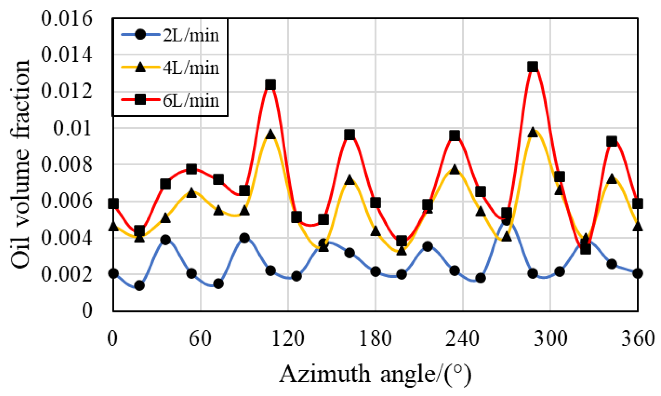
Figure 15 and Figure 16 show the volume fraction of the oil phase along the circumferential direction of the IBCR and OBCR at different bearing rotating speeds. The oil phase distribution in the two regions has periodicity. After entering the bearing through the oil supply hole, the oil flows toward the outer ring region, causing the oil to concentrate mainly in the OBCR. The amount of oil in the IBCR is low, and the oil supply hole is located on the inner ring. Therefore, compared with OBCR, the periodicity of IBCR is more obvious. When the oil flow rate is 2 L/min, the oil distribution in the OBCR is still very even. When the oil flow rate increased to 6 L/min, significant fluctuations appeared. Accordingly, as the oil flow rate increases, the circumferential distribution in various regions of the bearing becomes increasingly uneven.

3.4. Effects of Oil Viscosity

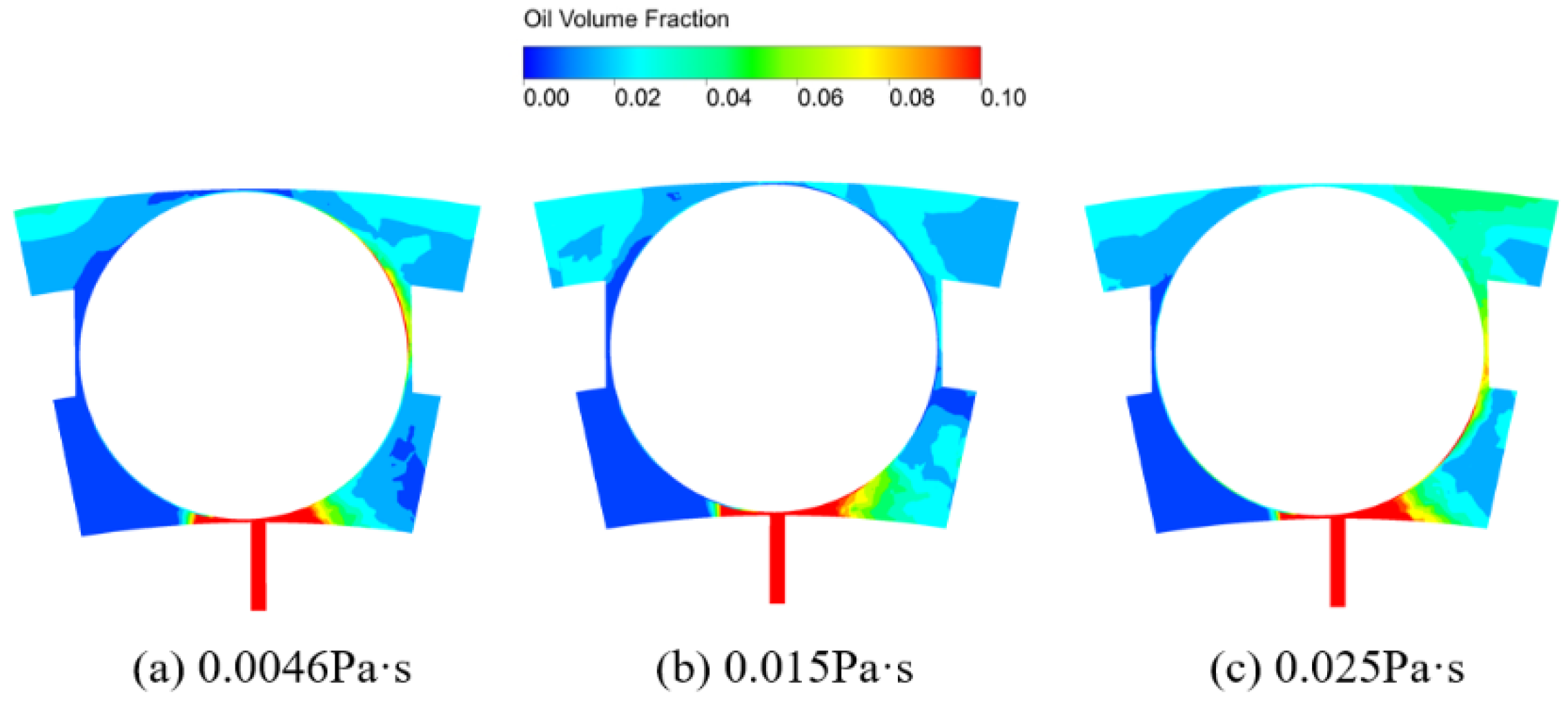
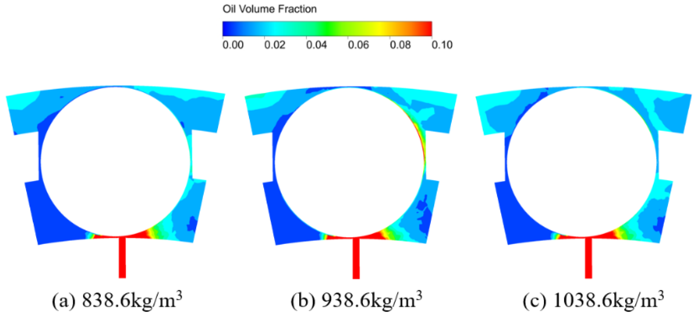
During the movement of the bearing, the physical properties of the fluid inside the bearing, such as viscosity, change with temperature. Figure 17 shows the streamline diagram at different oil viscosities. As the oil viscosity changes, the velocity of the fluid inside the bearing remains essentially unchanged. Figure 18 shows the oil‒gas two-phase distribution in the contact region of the bearing under different oil viscosities. As the viscosity of the lubricating oil increases, the amount of oil inside the bearing increases and is concentrated in the outer ring region, which is consistent with the changes in the rotating speed and flow rate of the bearing.
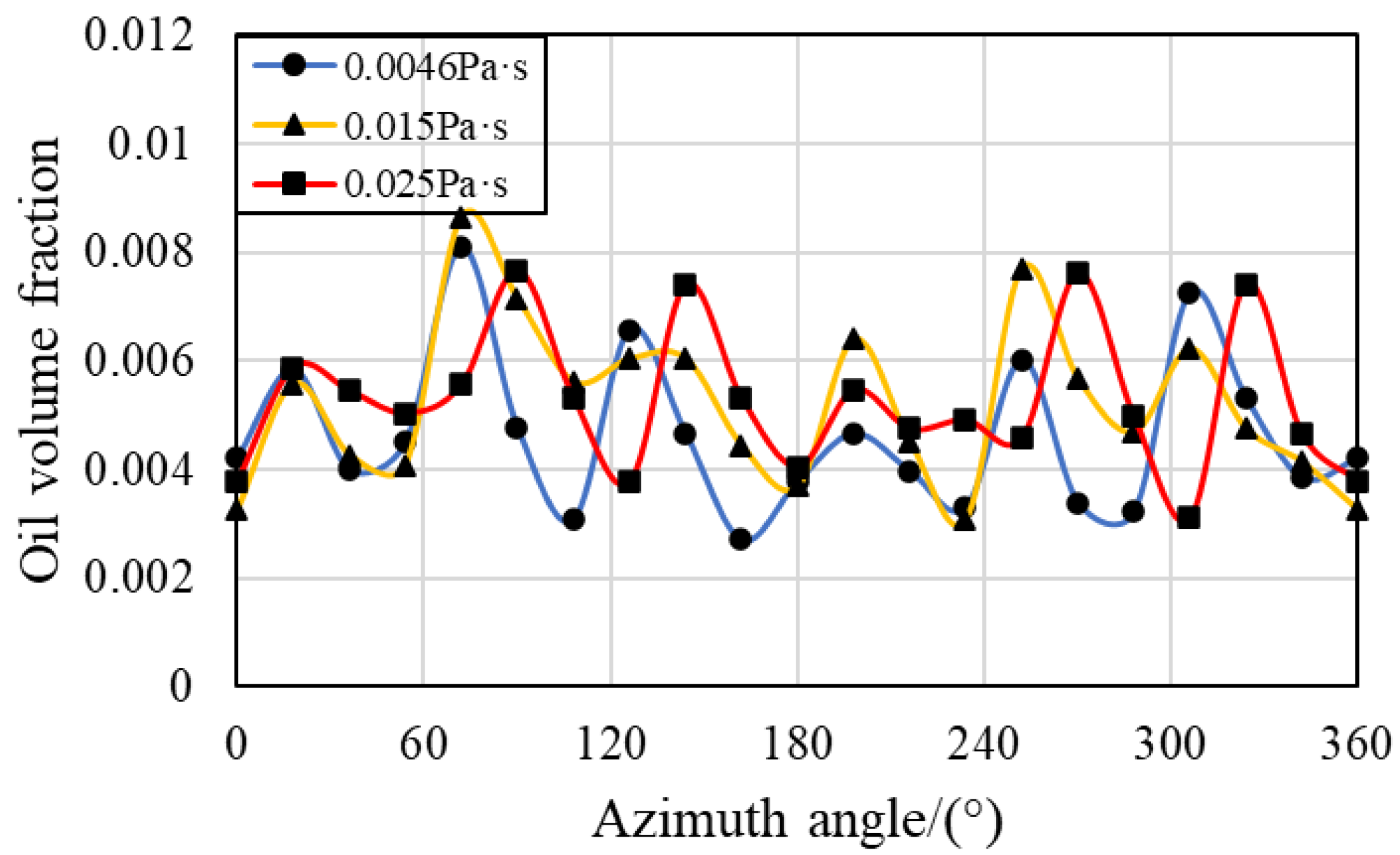
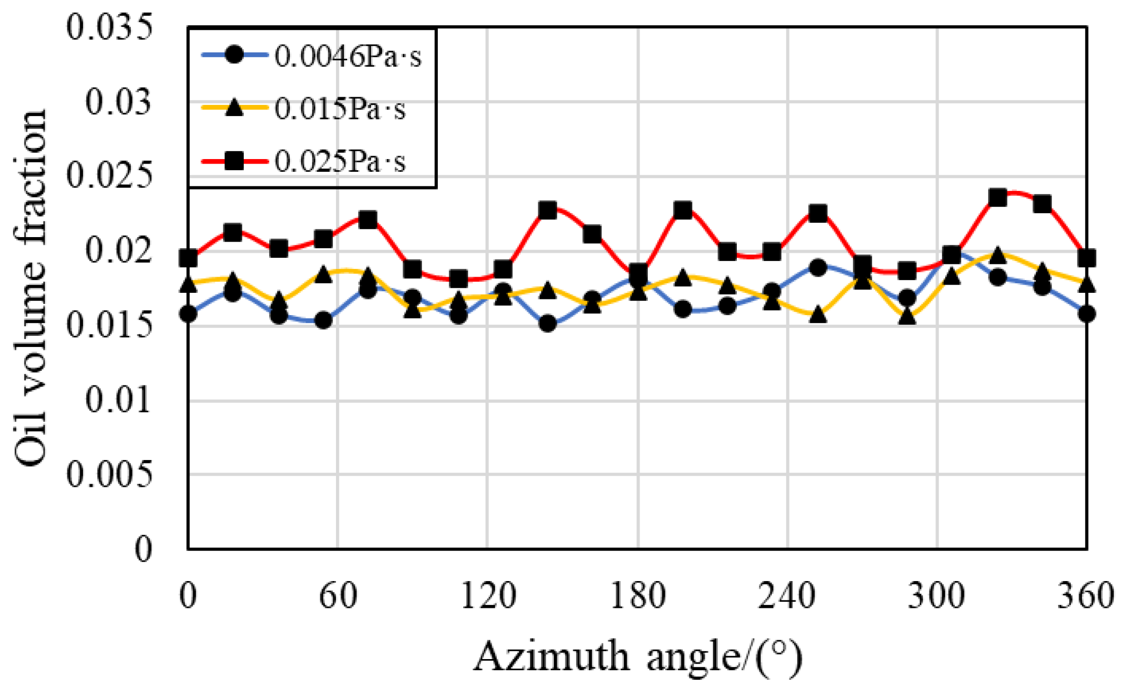
Figure 19 shows the volume fraction of the oil phase along the circumferential direction of the IBCR at different oil viscosities. When the oil viscosity is changed, the volume fraction of the oil phase in the IBCR of the bearing remains essentially unchanged. Compared with that in the IBCR, the volume fraction of the oil phase in the OBCR increases with increasing oil viscosity, as shown in Figure 20. Therefore, increasing the viscosity of the oil mainly affects the volume fraction of the oil phase in OBCR. By changing the oil viscosity, the periodicity of these two regions remains unchanged.

3.5. Effect of Oil Density

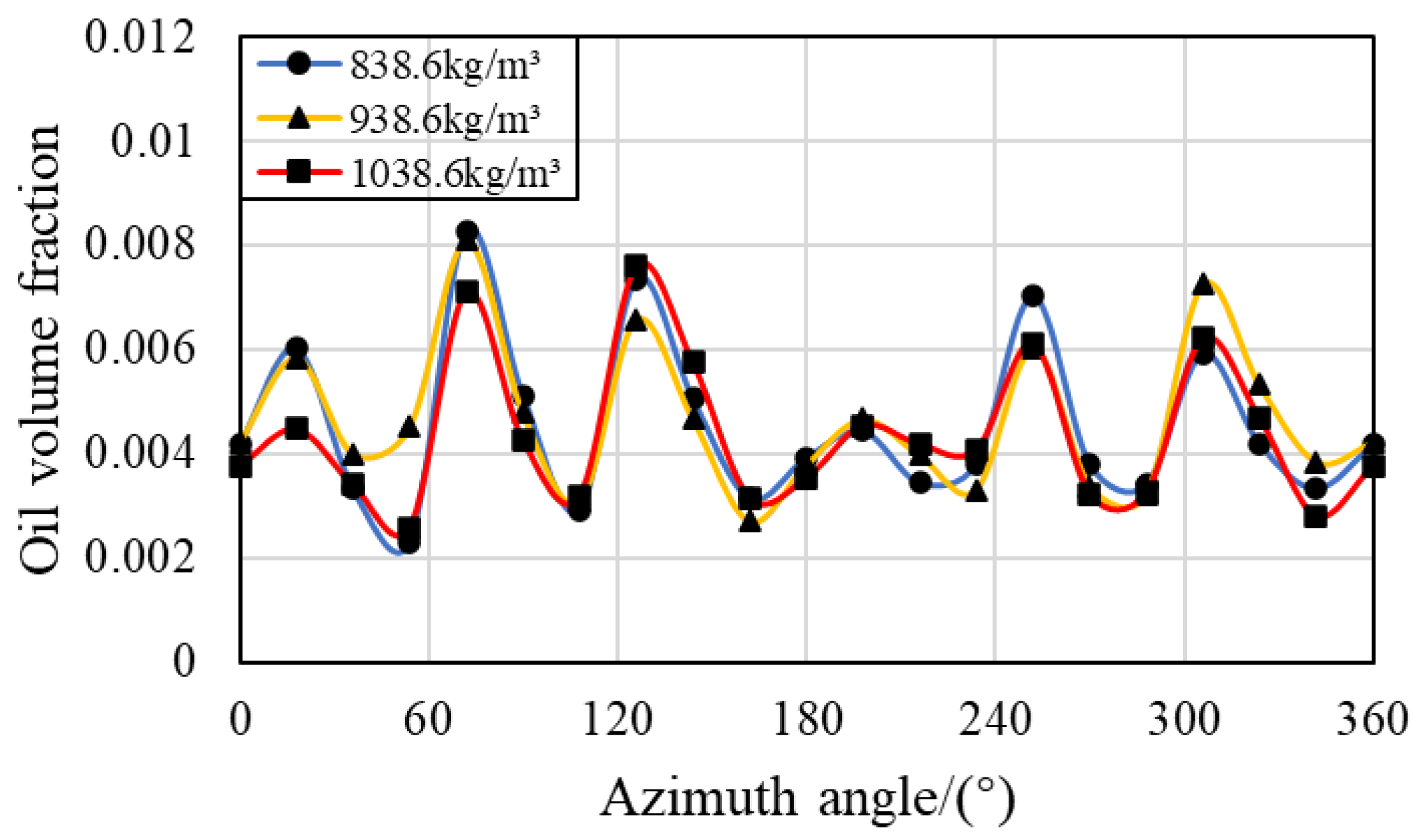
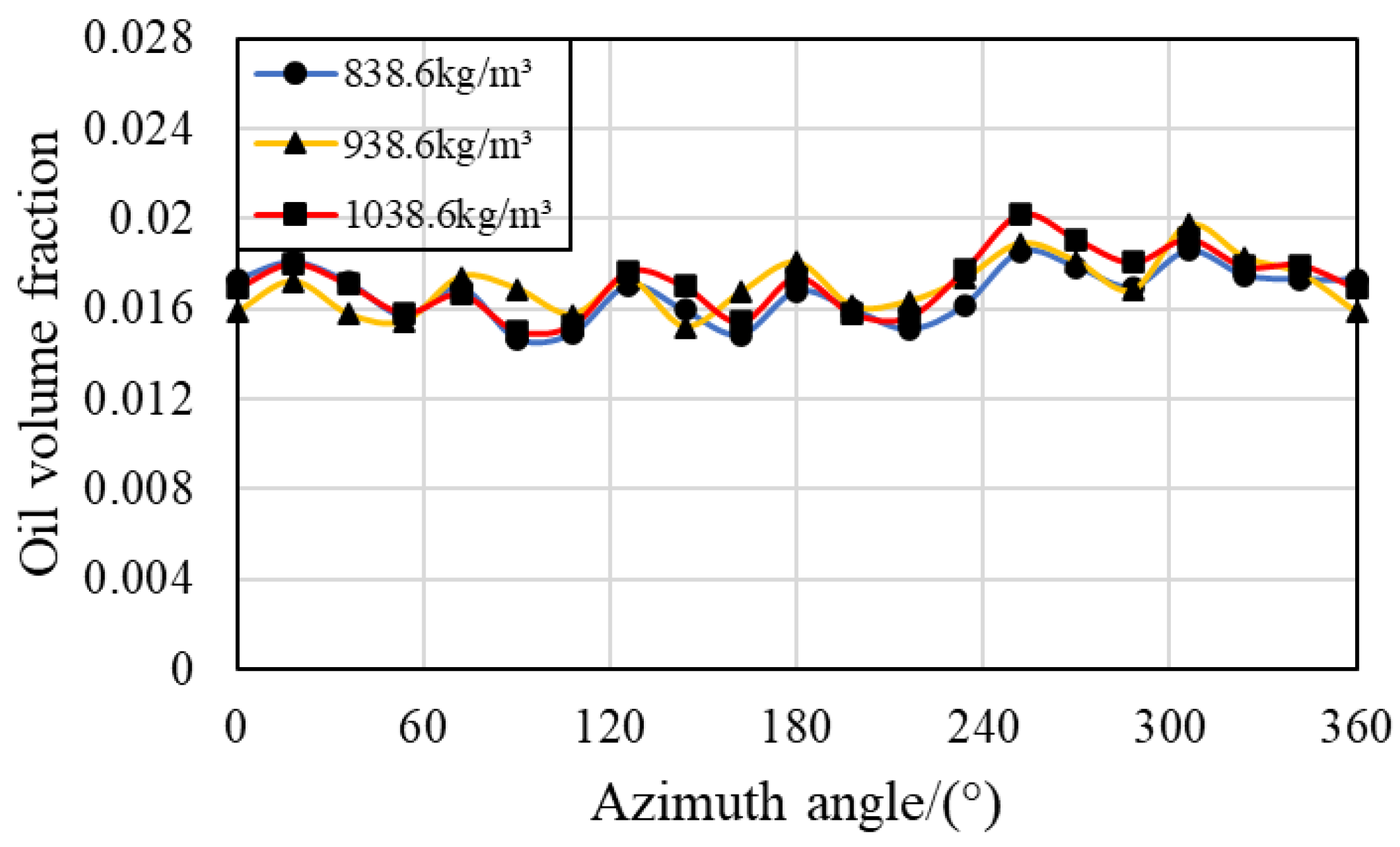
During the movement of the bearing, the fluid density also changes. When the oil density is changed, the fluid velocity and flow state inside the bearing remain basically unchanged, as shown in Figure 21. Figure 22 shows that the two-phase distribution of oil in the bearing remains unchanged. The variation law and periodicity of the oil‒gas two-phases in the IBCR and OBCR of the bearing also remain unchanged, as shown in Figure 23 and Figure 24.

4. Conclusions

In this work, a model of under-race lubrication ball bearing is established, and the oil‒gas two‒phase distribution in the ball‒raceway contact local region of the bearing is studied via a numerical simulation method. The motion state of the fluid in the inner raceway-ball contact local region (IBCR) and the outer raceway-ball contact local region (OBCR), as well as the distribution of the oil and gas phases with changes in the rotating speed, oil flow rate, oil viscosity and oil density of the bearing, are studied. The salient findings are summarized as follows:
(1)
There is a clear periodic variation pattern in the IBCR and OBCR of the bearing over time and space. In terms of time, periodicity is related to the number of fuel supply holes, the speed of the retainer, and the speed of the inner ring. The period in space is related only to the number of oil control holes.
(2)
The distribution of lubricant oil inside the bearing is uneven, with more oil near the oil supply hole in the circumferential direction, and it is mainly concentrated in the outer ring region in the radial direction because of the centrifugal force caused by the rotation of the bearing. Compared with that in the IBCR, the oil phase distribution in the OBCR is more uniform.
(3)
Increasing the bearing rotation speed reduces the oil volume fraction in the IBCR and OBCR, resulting in a more uniform distribution of the oil phase. Increasing the oil flow rate results in an increase in the oil volume fraction of the IBCR and OBCR and an increase in fluctuations in the oil phase distribution. Increasing the oil viscosity only increases the oil volume fraction of the OBCR and causes an increase in fluctuations in the OBCR. The oil density does not affect the volume fraction or uniformity of the oil phase.
(4)
Compared with the outer raceway-ball contact region, it is more difficult to keep lubricating oil in the inner raceway-ball contact region. If the oil supply condition becomes worse or the bearing rotates faster, it is easier for the inner raceway to experience lubrication failure and frictional wear.

Author Contributions

Conceptualization, Q.Y. and W.G.; methodology, P.G.; software, Y.L. and C.L.; validation, W.G. and P.G.; writing—original draft preparation, W.G. and P.G.; visualization, Q.Y. and Y.L.; funding acquisition, W.G. All authors have read and agreed to the published version of the manuscript.

Funding

This research was funded by the Key Research and Development Program of Shaanxi (Grant number: 2024GX-YB-XM-014), Science Center for Gas Turbine Project (Grant number: P2022-B-III-003-001), and the National Science and Technology Major Project of China (Grant number: J2019-Ⅲ-0023-0067).

Conflicts of Interest

The authors declare no conflicts of interest. The funders had no role in the design of the study; in the collection, analyses, or interpretation of data; in the writing of the manuscript; or in the decision to publish the results.

References

  1. Gao, W.; Nelias, D.; Li, K.; Liu, Z.; Lyu, Y. A multiphase computational study of oil distribution inside roller bearings with under-race lubrication. Tribol. Int. 2019, 140. [Google Scholar] [CrossRef]
  2. Gloeckner, P.; Dullenkopf, K.; Flouros, M. Direct Outer Ring Cooling of a High Speed Jet Engine Mainshaft Ball Bearing: Experimental Investigation Results. J. Eng. Gas Turbines Power 2011, 133, 062503. [Google Scholar] [CrossRef]
  3. Pinel, S.I.; Signer, H.R.; Zaretsky, E.V. Comparison Between Oil-Mist and Oil-Jet Lubrication of High-Speed, Small-Bore, Angular-Contact Ball Bearings. Tribol. Trans. 2001, 44, 327–338. [Google Scholar] [CrossRef]
  4. Jiang, L.; Lyu, Y.; Gao, W.; Zhu, P.; Liu, Z. Numerical investigation of the oil–air distribution inside ball bearings with under-race lubrication. Proc. Inst. Mech. Eng. Part J: J. Eng. Tribol. 2021, 236, 499–513. [Google Scholar] [CrossRef]
  5. Gao, W.; Lyu, Y.; Liu, Z.; Nelias, D. Validation and application of a numerical approach for the estimation of drag and churning losses in high speed roller bearings. Appl. Therm. Eng. 2019, 153, 390–397. [Google Scholar] [CrossRef]
  6. Zhao, Y.; Zi, Y.; Chen, Z.; Zhang, M.; Zhu, Y.; Yin, J. Power loss investigation of ball bearings considering rolling-sliding contacts. Int. J. Mech. Sci. 2023, 250. [Google Scholar] [CrossRef]
  7. Wu, W.; Hu, C.; Hu, J.; Yuan, S.; Zhang, R. Jet cooling characteristics for ball bearings using the VOF multiphase model. Int. J. Therm. Sci. 2017, 116, 150–158. [Google Scholar] [CrossRef]
  8. Gao, W.; Li, C.; Li, Y.; Liu, Z.; Lyu, Y. Oil–Air Two-Phase Flow Distribution Characteristics inside Cylindrical Roller Bearing with Under-Race Lubrication. Lubricants 2024, 12, 133. [Google Scholar] [CrossRef]
  9. Marchesse, Y.; Changenet, C.; Ville, F. Numerical Investigations on Drag Coefficient of Balls in Rolling Element Bearing. Tribol. Trans. 2014, 57, 778–785. [Google Scholar] [CrossRef]
  10. Yan K, Wang Y, Zhu Y, et al. Investigation on heat dissipation characteristic of ball bearing cage and inside cavity at ultra high rotation speed[J]. Tribology International, 2016, 93: 470-481.
  11. Jeng, Y.-R.; Gao, C.-C. Investigation of the ball-bearing temperature rise under an oil-air lubrication system. Proc. Inst. Mech. Eng. Part J: J. Eng. Tribol. 2001, 215, 139–148. [Google Scholar] [CrossRef]
  12. Flouros, M. Reduction of Power Losses in Bearing Chambers Using Porous Screens Surrounding a Ball Bearing. J. Eng. Gas Turbines Power 2005, 128, 178–182. [Google Scholar] [CrossRef]
  13. Jiang, S.; Mao, H. Investigation of the High Speed Rolling Bearing Temperature Rise With Oil-Air Lubrication. J. Tribol. 2011, 133, 021101. [Google Scholar] [CrossRef]
  14. Zeng, Q.; Zhang, J.; Hong, J.; Liu, C. A comparative study on simulation and experiment of oil-air lubrication unit for high speed bearing. Ind. Lubr. Tribol. 2016, 68, 325–335. [Google Scholar] [CrossRef]
  15. Wu, W.; Hu, J.; Yuan, S.; Hu, C. Numerical and experimental investigation of the stratified air-oil flow inside ball bearings. Int. J. Heat Mass Transf. 2016, 103, 619–626. [Google Scholar] [CrossRef]
  16. Yan, K.; Zhang, J.; Hong, J.; Wang, Y.; Zhu, Y. Structural optimization of lubrication device for high speed angular contact ball bearing based on internal fluid flow analysis. Int. J. Heat Mass Transf. 2016, 95, 540–550. [Google Scholar] [CrossRef]
  17. Bao, H.; Hou, X.; Lu, F. Analysis of Oil-Air Two-Phase Flow Characteristics inside a Ball Bearing with Under-Race Lubrication. Processes 2020, 8, 1223. [Google Scholar] [CrossRef]
  18. Peterson, W.; Russell, T.; Sadeghi, F.; Berhan, M.T.; Stacke, L.-E.; Ståhl, J. A CFD investigation of lubricant flow in deep groove ball bearings. Tribol. Int. 2021, 154, 106735. [Google Scholar] [CrossRef]
  19. Liu, J.; Ni, H.; Xu, Z.; Pan, G. A simulation analysis for lubricating characteristics of an oil-jet lubricated ball bearing. Simul. Model. Pr. Theory 2021, 113. [Google Scholar] [CrossRef]
  20. Zhang, J.J.; Lu, L.M.; Zheng, Z.Y.; Gan, L.; Lv, Z.Y. Visual Comparative Analysis for the Oil-air Two-Phase Flow of An Oil-Jet Lubricated Roller-Sliding Bearing. J. Appl. Fluid Mech. 2023, 16, 179–191. [Google Scholar] [CrossRef]
  21. Shan W, Chen Y, Huang J, et al. A multiphase flow study for lubrication characteristics on the internal flow pattern of ball bearing[J]. Results in Engineering, 2023, 20: 101429.
  22. Hirt CW and Nichols, BD. Volume of fluid (VOF) method for the dynamics of free boundaries. J Comput Phys 1981; 39: 201–225.
  23. Xiao, J.; Zhu, E.; Wang, G. Numerical Simulation of Emergency Shutdown Process of Ring Gate in Hydraulic Turbine Runaway. J. Fluids Eng. 2012, 134, 124501. [Google Scholar] [CrossRef]
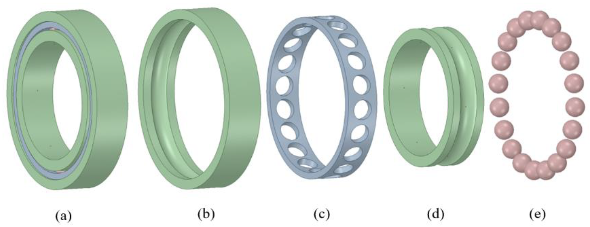
Figure 1. Geometric model of under-race lubrication ball bearing: (a) ball bearing, (b) outer ring, (c) cage, (d) inner ring, (e) balls.
Preprints 116273 g001
Figure 2. Calculational domain.
Preprints 116273 g002
Figure 3. Mesh and boundary conditions.
Preprints 116273 g003
Figure 4. Oil and gas distribution.
Preprints 116273 g004
Figure 5. Computational domain division.
Preprints 116273 g005
Figure 6. Circumferential oil volume fraction in different regions.
Preprints 116273 g006
Figure 7. Streamlines at different bearing rotating speeds.
Preprints 116273 g007
Figure 8. Oil and air distributions in the contact region at different bearing rotating speeds.
Preprints 116273 g008
Figure 9. Oil phase volume fraction in the IBCR at different bearing rotating speeds.
Preprints 116273 g009
Figure 10. Oil phase volume fraction in the OBCR at different bearing rotating speeds.
Preprints 116273 g010
Figure 11. Circumferential oil phase volume fraction in the IBCR at different rotation speeds.
Preprints 116273 g011
Figure 12. Circumferential oil phase volume fraction in the OBCR at different rotation speeds.
Preprints 116273 g012
Figure 13. Streamlines at different oil flow rates.
Preprints 116273 g013
Figure 14. Oil and air distributions in the contact region at different oil flow rates.
Preprints 116273 g014
Figure 15. Circumferential oil phase volume fraction in the IBCR at different oil flow rates.
Preprints 116273 g015
Figure 16. Circumferential oil phase volume fraction in the OBCR at different oil flow rates.
Preprints 116273 g016
Figure 17. Streamlines at different oil viscosities.
Preprints 116273 g017
Figure 18. Oil and air distributions in the contact region at different oil viscosities.
Preprints 116273 g018
Figure 19. Circumferential oil phase volume fraction in the IBCR at different oil viscosities.
Preprints 116273 g019
Figure 20. Circumferential oil phase volume fraction in the OBCR at different oil viscosities.
Preprints 116273 g020
Figure 21. Streamlines at different oil densities.
Preprints 116273 g021
Figure 22. Oil and air distributions in the contact region at different oil densities.
Preprints 116273 g022
Figure 23. Circumferential oil phase volume fraction in the IBCR at different oil densities.
Preprints 116273 g023
Figure 24. Circumferential oil phase volume fraction in the OBCR at different oil densities.
Preprints 116273 g024
Table 1. Geometry parameters of ball bearing.
Geometry Parameters Specification
Inner race diameter/mm 133.35
Outer race diameter/mm 200
Ball diameter/mm 22
Ball number 20
Oil supply hole diameter/mm 1
Inner/outer race curve coefficient 0.52/0.515
Table 2. Mesh independence verification.
Number of grids Flow difference between the inlet and outlet
2543255 2.86%
3563698 2.45%
4325869 2.33%
Disclaimer/Publisher’s Note: The statements, opinions and data contained in all publications are solely those of the individual author(s) and contributor(s) and not of MDPI and/or the editor(s). MDPI and/or the editor(s) disclaim responsibility for any injury to people or property resulting from any ideas, methods, instructions or products referred to in the content.
Copyright: This open access article is published under a Creative Commons CC BY 4.0 license, which permit the free download, distribution, and reuse, provided that the author and preprint are cited in any reuse.
Prerpints.org logo

Preprints.org is a free preprint server supported by MDPI in Basel, Switzerland.

Subscribe

© 2024 MDPI (Basel, Switzerland) unless otherwise stated