Submitted:
24 August 2024
Posted:
27 August 2024
You are already at the latest version
Abstract
Keywords:
1. Introduction
2. Device Design and Principle of Operation
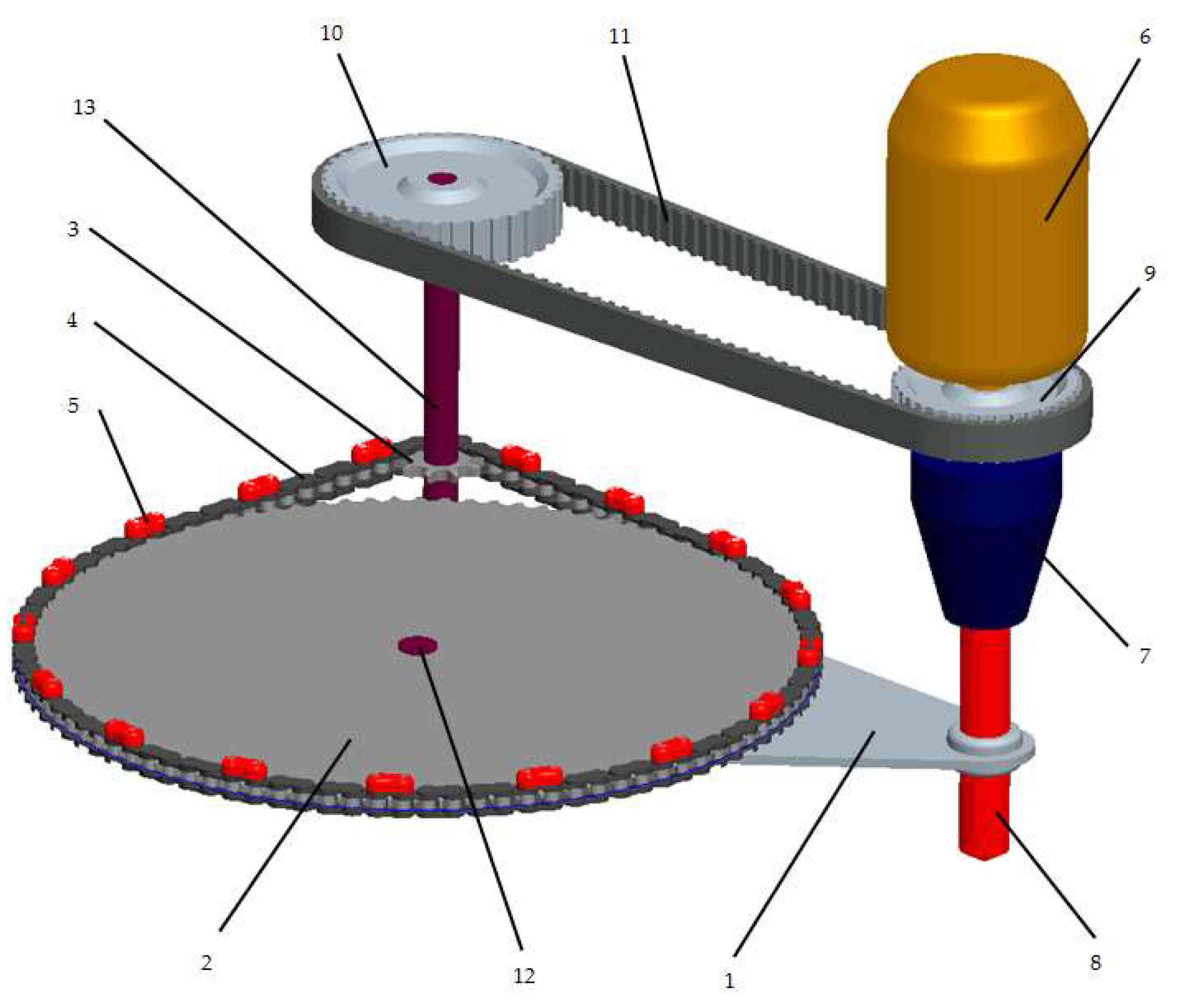
- support frame;
- chain wheel RC1;
- chain wheel RC2;
- chain;
- mass weights;
- drive motor;
- tool clamping chuck;
- tool;
- belt wheel RB1;
- belt wheel RB2;
- synchronous belt;
- fixing pin;
- shaft.
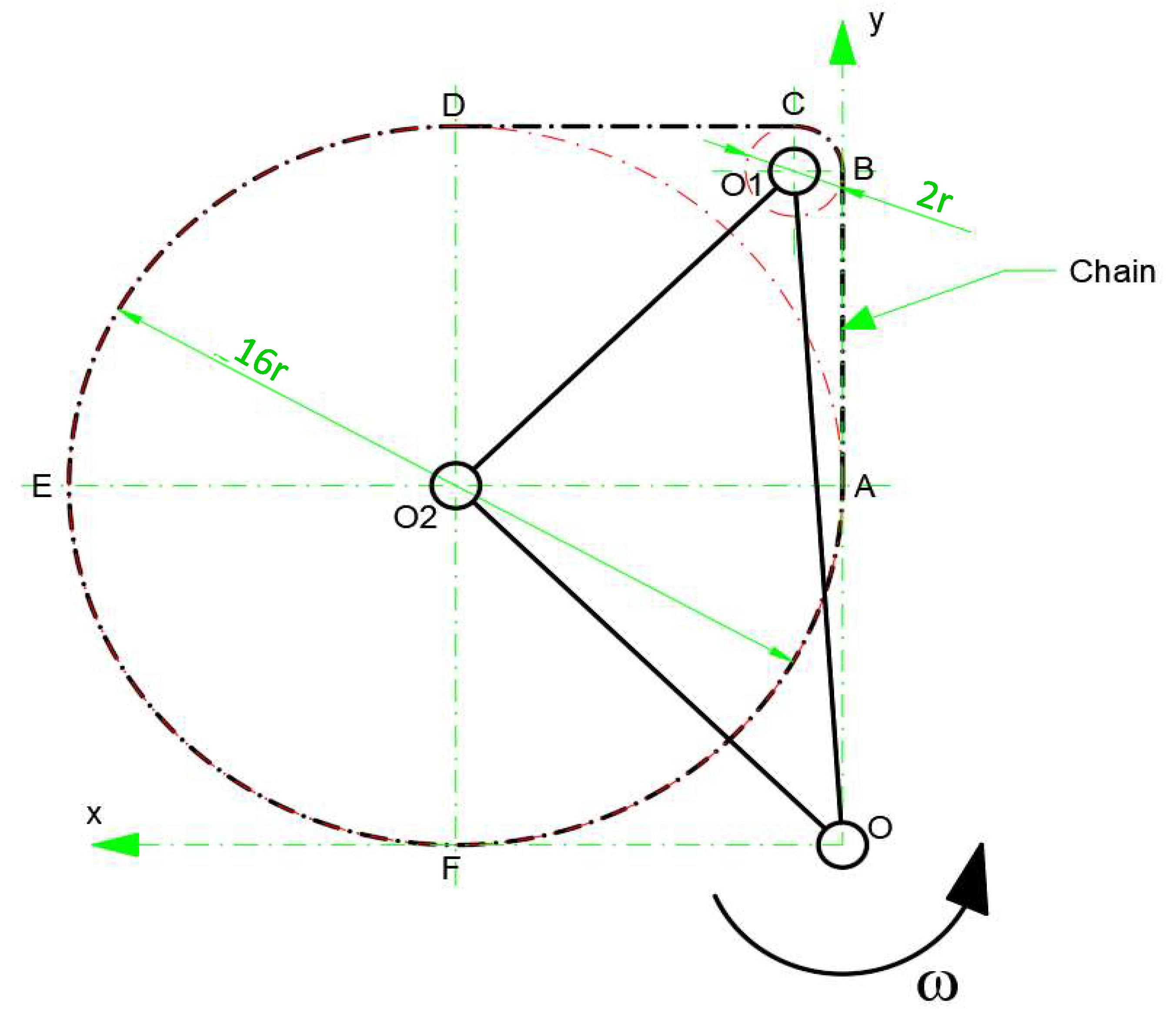
- M-mass of the rotating body;
- ω- angular speed of the mass;
- -trajectory radius of the body’s center of gravity relative to the center of rotation O.
3. Analytical Computation of System Dynamics
4. Numerical Example and Discussion
5. Conclusions
- The torque developed by the device is constant, if the polygonal effect of the chain is neglected.
- For the exemplified technical data, the device can generate a supplementation of the nominal torque with 54,3%.
- The additional torque generated by the device is independent of the drive power, the system showing a higher efficiency as the nominal motor power decreases.
- The torque produced by the system can be increased by raising the masses which are added to the chain, by increasing the radii of the chain wheels and by raising the driving speed.
- If during the operation, appears suddenly an increase of the resisting torque at the working tool, the reaction moment that occurs at the motor is mitigated by this device, making the handling of the entire system easier.
- Optimize the design so as to minimize the size of the device;
- Build a prototype of the device and carry out tests trials;
- Investigate how the additional moment, generated by the masses attached to the chain, is influenced, if the transmission ratio of the synchronous belt is different from 1
Author Contributions
Conflicts of Interest
References
- Halliday, D.; Resnick, R.; Walker, J. Fundamental of physics, 12th ed.; Wiley: New York, USA, 2021; pp. 101-131.
- Colli, A.; Zanotti, A.; Giuseppe, G. Wind-tunnel experimental investigation on rotor-rotor aerodynamic interaction in compound helicopter configuration. Aerosp. Sci. Technol. 2024, 109420.
- Gunaltili, E.; Ekici, S.; Kalkan, A.; Gocmen, F.E.; Kale, U.; Yilmazoglu, Z.; Karakoc, T.H. Conceptual design and optimization of a sustainable and environmentally friendly archetypal helicopter within the selection criteria and limitations, Heliyon 2023, 9(6).
- Balli, O. Exergetic, sustainability and environmental assessments of a turboshaft engine used on helicopter, Energy 2023, 127593.
- Castillo-Rivera, S.; Tomas-Rodriguez, M. Helicopter modelling and study of the accelerated rotor, Adv. Eng. Softw. 2018, 115, 52-65.
- Surette, J. 5 reasons why the Boeing CH-47 'Chinook' helicopter is still going strong after six decades. Published Sep 26, 2023. Available online: https://simpleflying.com/boeing-ch-47-chinook-longevity-aspects-list/ (accessed on 28 July 2024).
- Duan, D.; Leng, G.; Gao, J.; Feng, X.; Li, J. Load distribution strategy for multi-lift system with helicopters based on power consumption and robust adaptive game control. Chinese. J. Aeronaut. 2023, 36(4), 268-285.
- Geng, J.Y.; Langelaan, J.W. Cooperative transport of a slung load using load-leading control. J. Guid. Control Dyn. 2020, 43,1313–1331.
- Chopra, O; Ghose, D. Distributed control for multiple UAV transport of slung loads. In Proceedings of AIAA SCITECH 2022 Forum, San Diego, USA, 3-7 January 2022.
- Mokhtar, T.; Soltan, T.; Abdelrahman, M.M. Helicopter performance enhancement by alleviating retreating blade stall using active flow control, Sci. Afr. 2023, 21, e01888.
- Yu, D.; Che, T.; Zhang, H.; Li, C.; Wang,C.; Wang, Z. Optimizing terrestrial locomotion of undulating-fin amphibious robots: Asynchronous control and phase-difference optimization. Ocean Eng. 2024, 303, 117755.
- Wu, J.; Yao, Y. Design and analysis of a novel walking vehicle based on leg mechanism with variable topologies. J. Mechanism and Machine Theory 2018, 128, 663–681.
- Scales, J.; Coleman, D.; Brown, M. Multiday load carriage decreases ability to mitigate ground reaction force through reduction of ankle torque production, Appl. Ergon 2022, 101, 103717.
- Chan, V.C.H.; Ross G.B.; Clouthier, A.L.; Fischer, S.L.; Graham, R.B. The role of machine learning in the primary prevention of work-related musculoskeletal disorders: A scoping review, Appl. Ergon 2022, 98, 103574.
- Coulombe, M. Differential Displacement Device under Simultaneous and Repetitive Electromagnetic Repulsive Forces. US Patent No. 7909669, 10 May 2010.
- Benjamin, P.M. Centrifugal Thrust Motor. US Patent No. 3750484, 7 August 1973.
- Booden, J.D. Electromagnetically Actuated Thrust Generator. US Patent No. 5782134, 21 July 1998.
- Cuff, C.I. Device for Converting Rotary Motion into Unidirectional Motio. US Patent No. 4095460, 20 June 1978.
- Dobos. E. M. Propulsion Apparatus. US Patent No. 4579011, 1 April 1986.
- Farrall, A.W. Inertial Propulsion Device. US Patent No. 3266233, 16 August 1966.
- Fulop, C. Flywheel. US Patent No. 4788882, 6 December 1988.
- Haller, P. Propulsion Apparatus. US Patent No. 3177660, 13 April 1965.
- Kellogg, H.D. Gyroscopic Inertial Space Drive. US Patent No. 3203644,31 August 1965.
- Mendez Llamozas, J.D. Direct Push Propulsion Unit. US Patent No. 2636340, 28 April 1953.
- North, H. Apparatus for Producing a Force. US Patent No. 4712439, 15 December 1987.
- Oades, R.A. Apparatus for Generating a Propulsion Force. US Patent No. 5890400, 6 April 1999.
- Shimshi, E. Apparatus for Energy Transformation and Conservation. US Patent No. 5673872, 7 October 1997.
- Schnur, N.J. Method and Apparatus for Propelling an Object by an Unbalanced Centrifugal Force with Continuous Motion. US Patent No. 3979961, 14 September 1976.
- Deschamplain, D. Motion Imparting System. US Patent No. 6259177B1, 10 July 2001.
- Marsh, R.O. Centrifugal Drive Machine. US Patent No. 5388470, 14 February 1995.
- Murray, L.D. Mechanical Force Generator. US Patent No. 6290622B1, 18 September 2001.
- Kunz, W.T. Centrifugal Propulsion System. US Patent No. 5937698, 17 August 1999.
- Woltermg, H.M. Rotating Eccentric Weights Vibrator System. US Patent No. 5388469, 14 February 1995.
- Dean, N.L. System for Converting Rotary Motion into Unidirectional Motion. US Patent No. 2886976, 19 May 1959.
- Thornson, B.R. Apparatus for Developing Propulsion Force. US Patent No. 4631971, 30 December 1986.
- Goncharevich, I.F. Dynamics of vibrational transportation. Nauka, Moscow, 1972; p. 244 [in Russian].
- Gerocs, A.; Gillich, G.R.; Nedelcu, D.; Korka, Z.I. A Multibody Inertial Propulsion Drive with Symmetrically Placed Balls Rotating on Eccentric Trajectories. Symmetry 2020, 12, 1422.
- Blekhman I.I., “Vibrational Mechanics: Nonlinear dynamic effects, General approach, Applications”, World Scientific, Singapore, 2000, p.15 and p.19.
- Gerocs, A.; Korka, Z.I.; Biro, I.; Cojocaru, V. Analytical investigation of an inertial propulsion system using rotating masses. J. Phys.: Conf. Ser. 2020, 1426 012031.
- Kononenko, V. O., Vibrating Systems with a Limited Power Supply. Iliffe Books Ltd: London, 1969, p.24 (in English). Translated from Russian: V. O. Kononenko, Oscillatory Systems with Limited Excitation. Moscow, Nauka, 1964.
- Blekhman, I.I. Synchronization in Science and Technology. ASME Press: New York, 1988 (in English, translated from Russian).
- Timofte, S.; Miclosina, C.O.; Cojocaru, V.; Gerocs, A.; Korka, Z.I. Inertial Propulsion of a Mobile Platform Driven by Two Eccentric Bodies. Appl. Sci. 2023, 13, 9511.
- Majewski. T. Vibratory Forces and Synchronization in Physical Systems. Ingeniería Mecánica Tecnología y Desarrollo 2013, 4(4), 119 – 128.
- Timofte, S.; Korka, Z.I.; Gerocs, A.; Wisznovszky, S.; Sfetcu, C.R. Kinematic and Dynamic Investigation of a Novel Inertial Propulsion Drive. Analecta Technica Szegedinensia 2022, 16(1), 27-32.
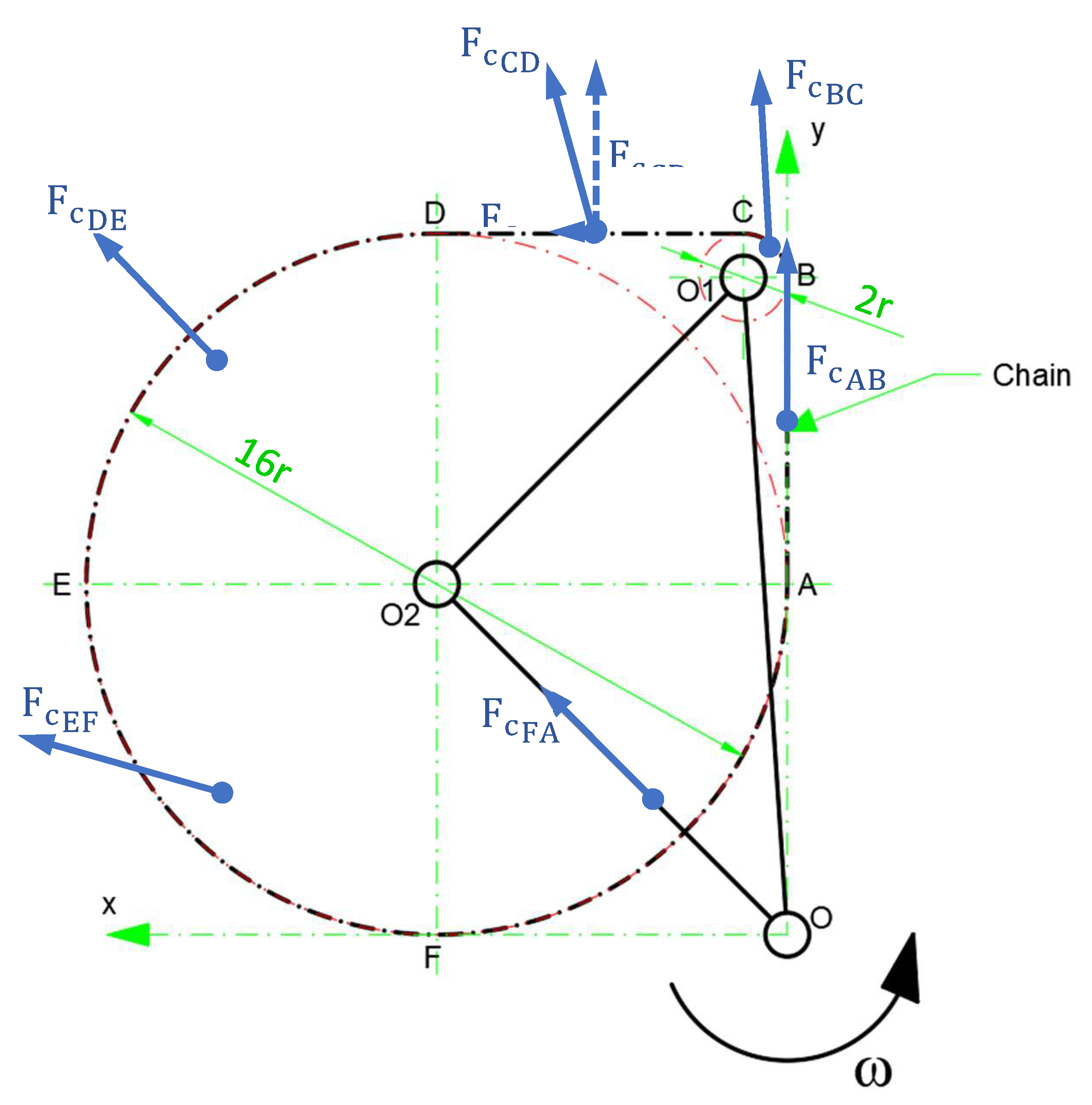
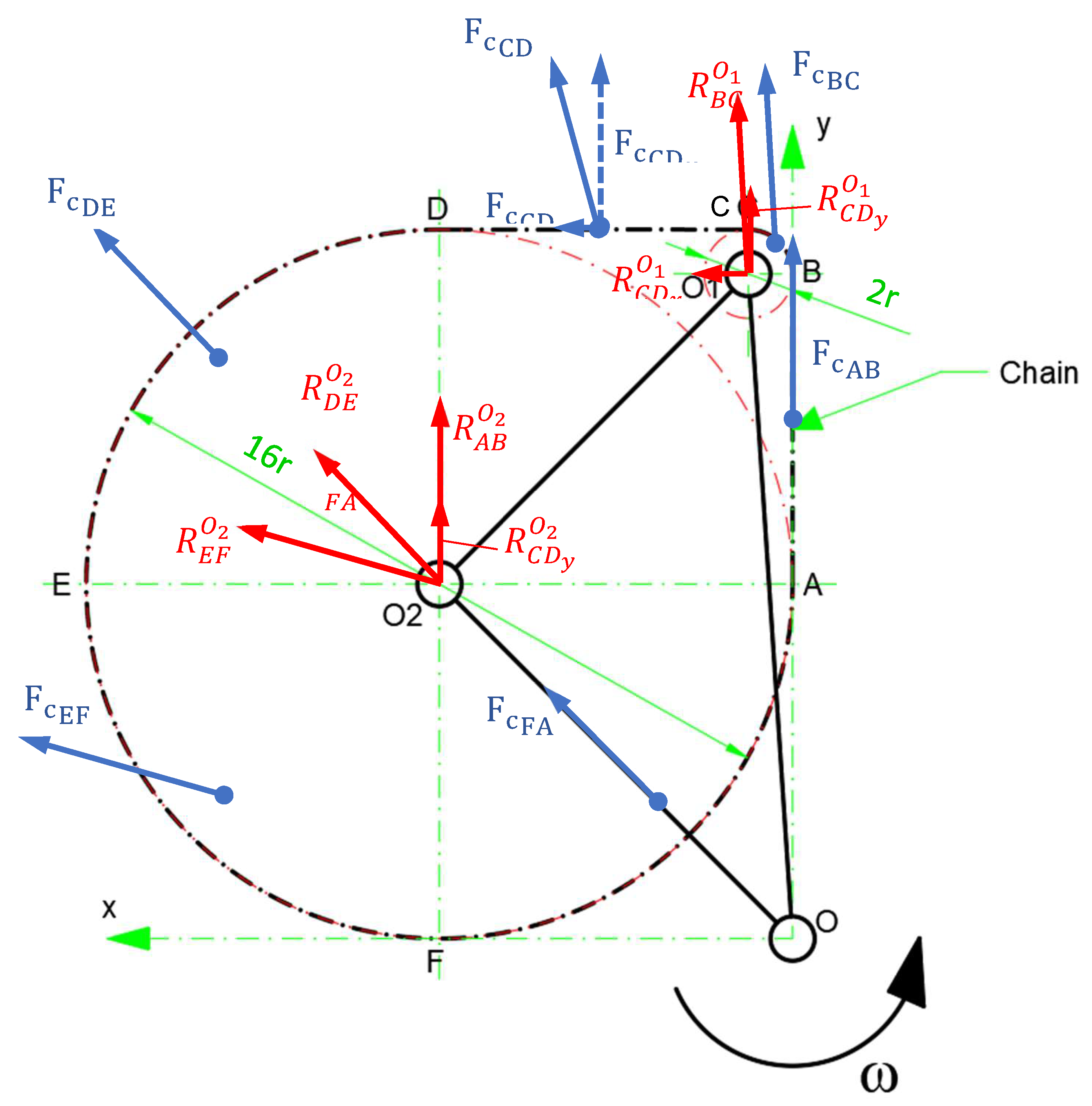
| Centrifugal force | Produced torque at the rotation point | |
|---|---|---|
| O1 | O2 | |
| 0 | ||
| 0 | ||
| 0 | ||
| 0 | 0 | |
| 0 | ||
| 0 | 0 | |
| Technical data | |
|---|---|
| Toll driving power | P= 500 [W] |
| Driving speed | n= 600 [min-1] |
| Specific mass of the weights | |
| Radius of the small chain wheel | r= 0.05 [m] |
Disclaimer/Publisher’s Note: The statements, opinions and data contained in all publications are solely those of the individual author(s) and contributor(s) and not of MDPI and/or the editor(s). MDPI and/or the editor(s) disclaim responsibility for any injury to people or property resulting from any ideas, methods, instructions or products referred to in the content. |
© 2024 by the authors. Licensee MDPI, Basel, Switzerland. This article is an open access article distributed under the terms and conditions of the Creative Commons Attribution (CC BY) license (http://creativecommons.org/licenses/by/4.0/).


