1. Introduction
The alkaline treatment of clay and clay minerals has been a widely studied topic in the past decades due to its potential for forming geopolymers, which serve as alternative binders with reduced environmental impact and increased durability [
1,
2]. Additionally, alkaline treatment can lower the sintering temperature of ceramic materials [
3]. It is also known that applying alkaline treatment to clay minerals, such as kaolinite, can yield microporous materials such as zeolites, which are used as ion exchangers [
4], molecular sieves [
5], sorbents, catalysts [
6], and gas adsorbers [
7].
In alkali-activated systems, any material containing a certain amount of silicon and aluminum can be used as a precursor, either in amorphous or crystalline form, soluble in an alkaline solution. The dissolution of alumosilicate precursors breaks down their structure to form aluminate and silicate oligomers, which then undergo a nucleation and crystallization growth process [
8]. The type of material formed in the alkaline treatment process depends on several compositional and processing factors, such as the Si:Al ratio. Geopolymers typically form at Si:Al ratios greater than 1.5, while crystalline zeolites form at Si:Al ratios below 1.5 [
9]. However, some types of zeolites can have Si:Al ratios of up to 2.5 [
7]. The crystalline structure of the precursor is also important as it has a significant impact on the dissolution kinetics in alkaline media [
10]. To improve the chemical activity, pretreatment of the raw materials can be used, most often calcination [
11]. Mechanical [
1] and chemical [
12] pretreatment can also be performed. The curing temperature and conditions after alkaline treatment influence the end result. For geopolymer synthesis, temperatures below 100°C are typically used [
13], wshile higher temperatures and hydrothermal conditions are required for zeolite formation [
14].
Most of the research in the area of alkali-activated materials is focused on industrial waste products, primarily fly ash and blast furnace slag, as well as on 1:1 type clay minerals, such as kaolinite, which have a tetrahedral-octahedral (T-O) configuration [
5]. Alkaline treatment with Ca, Na, and K hydroxides, followed by curing at low temperatures for an extended period, is a common method for producing geopolymers from kaolinite. Kaolinite has the advantage of high purity and consistent composition. However, its Si:Al ratio is in the range of 0.9-1.1 [
15], which necessitates the addition of silica for the formation of geopolymers. Furthermore, the commercial availability of pure kaolinite is limited [
1].
Other clay minerals, such as illite and smectite, belong to the 2:1 type and have a T-O-T structure. Clay minerals with a 2:1 type structure, like illite, are more widely available and have the potential to form both geopolymers and zeolites [
16]. Due to their higher Si:Al ratio, an additional source of Si or the removal of Al is unnecessary. However, there are fewer studies focusing on illite as a precursor, and the alkali activation behavior of illite is still largely unknown. Nevertheless, existing studies suggest that illite is capable of forming alumosilicate products [
1]. It's important to note that clay minerals do not have fixed stoichiometric compositions, and their actual compositions will vary between different regions depending on the geological conditions of their formation [
17].
The 2:1 clay mineral structure of illite provides it with greater resistance to alkaline attack compared to kaolinite [
18]. As a result, a more intense treatment process is required to produce geopolymers and zeolites from illite, such as using higher concentration hydroxides and curing at elevated temperatures. Combination methods, such as alkaline-hydrothermal treatment or alkaline fusion followed by hydrothermal treatment, can be more effective for obtaining zeolites [
8].
The most commonly used alkaline solutions for these purposes are NaOH and KOH with concentrations of ≥5M. Both solutions serve the same function, but there are some differences. NaOH generally facilitates faster liquid phase formation, which is more favorable for zeolite formation, while KOH favors geopolymerization and achieves higher sample strength [
19].
An important step in the alkaline treatment process is clay calcination, during which the dehydroxylation of the octahedral layer reduces the coordination number of the Al atoms, making them more reactive [
20,
21]. Typical calcination temperatures for clay minerals range from 500-800 °C, depending on the type and structure of the clay mineral [
11]. For illite, the optimal calcination temperature is typically in the range of 550-650°C [
22].
The presence of cations (Fe
3+, Fe
2+, Mg
2+, Mn
2+) in both the structure of illite and as separate minerals in natural clays can have a beneficial effect by enhancing the catalytic properties of the synthesized product [
23,
24].
This study investigates the structural changes of illites through thermal-hydrothermal-alkali treatment for the synthesis of zeolites. The research focuses on the utilization of illite-glauconite clays, alkali activation using concentrated NaOH solutions, and the incorporation of thermal-hydrothermal processes.
3. Results
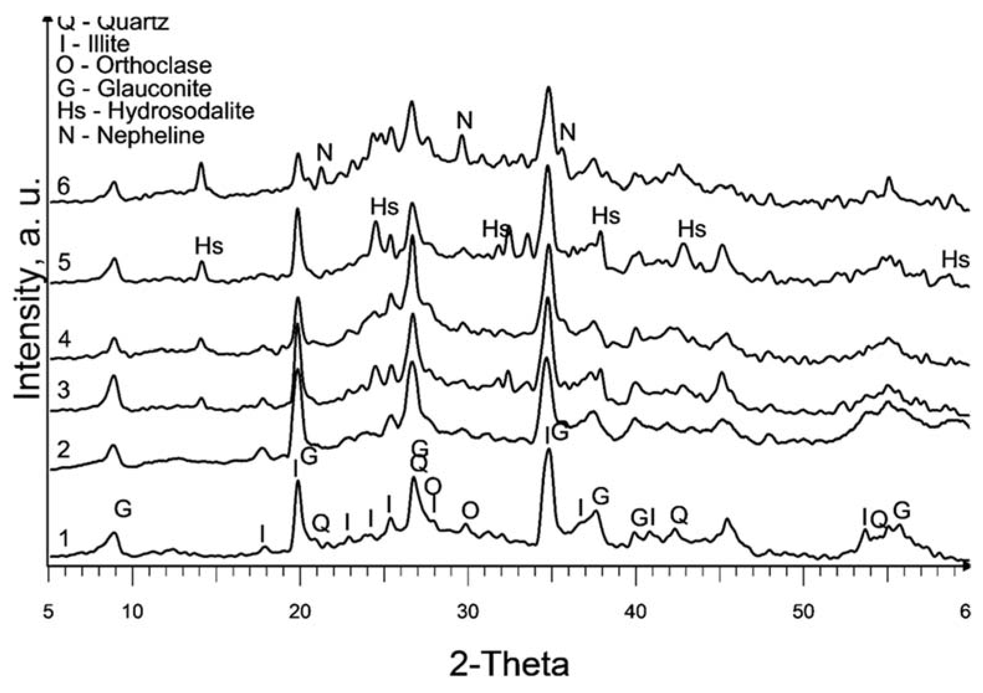
The XRD patterns of the raw and treated clay are displayed in
Figure 1. It is worth noting that the calcination at 580°C (sample 2) does not exhibit a significant change in the XRD pattern compared to the raw sedimented clay fraction (sample 1).
The dominant clay mineral observed here is illite, indicated by its primary diffraction peak at 2θ = 17.7° in both samples 1 and 2. Glauconite, with its main diffraction peaks at 2θ = 19.7° and 8.6°, is also present. It is important to note that there is a considerable overlap of glauconite and illite peaks. Glauconite is classified as a dioctahedral poorly structured mica with the formula [(K, Na)(Fe
3+,Al, Mg)
2(Si, Al)
4O
10(OH)
2]. It possesses a similar structure to illite, with Fe
3+ replacing Al
3+ as its octahedral cation [
26].
Partial dissolution of illite can be observed in all chemically treated samples, leading to a reduction in the intensity of the illite peaks. This effect is more pronounced in samples treated with 10M NaOH and subsequent curing at 600°C.
The primary new phase formed after alkaline treatment (samples 3 to 6) is hydrosodalite (Na₆[AlSiO₄]₆·8H₂O), as indicated by prominent diffraction peaks at 2θ = 14°, 2θ = 24.3°, and 2θ = 37.8°. Hydrosodalite is a sodalite-type material in which the central anion within the cage is replaced by four water molecules, requiring only three sodium ions to counterbalance the charge of the framework [
27]. The use of a higher concentration of NaOH enhances the formation of hydrosodalite by improving the solubility of clay minerals and providing an increased supply of sodium ions for the formation of hydrosodalite.
Increasing the curing temperature from 120°C to 600°C, however, leads to a slight reduction in hydrosodalite formation, as evidenced by lower peaks in XRD reflections. Hydrosodalite undergoes thermal degradation, primarily through the loss of water, especially at temperatures exceeding 400°C [
28]. At 600°C, hydrosodalite begins to transform into nepheline, as indicated by diffraction peaks at 2θ = 21.2° and 2θ = 29.7°. Nepheline belongs to the feldspathoid group and lacks a zeolitic structure [
29].
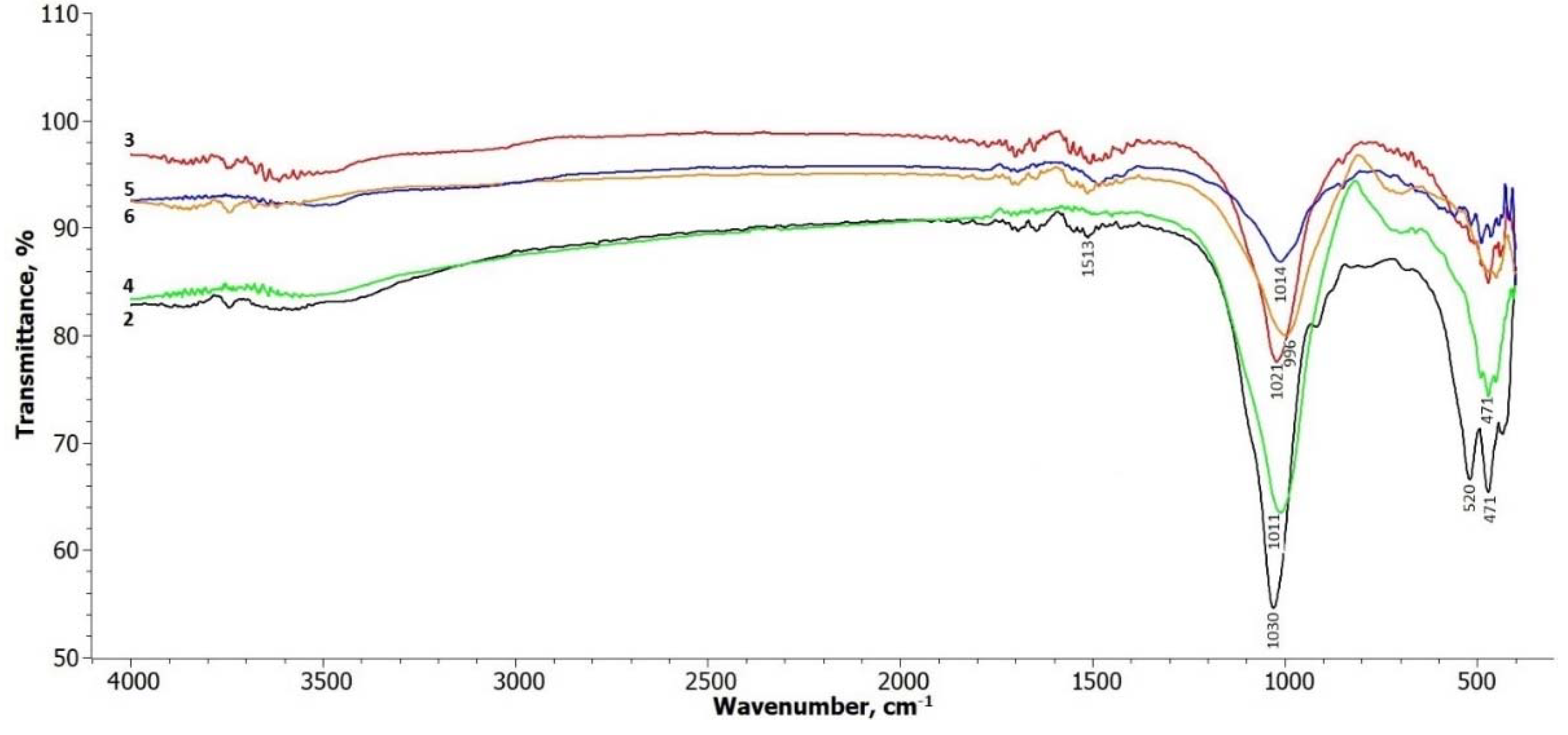
The FTIR spectra of the treated illite samples are shown in
Figure 2. In terms of the illite-glauconite structure, there are insignificant changes observed in the bands within the frequency range of 3700 – 3650 cm
-1, which are associated with the stretching of hydroxyl groups located at the edges of clay platelets [
30]. A slight broadening of these bands can be observed in the treated samples within this interval. The signals in the range up to 1500 cm
-1 are related to the presence of physically adsorbed water molecules on the illite platelets (Komadel & Madejová, 2006), and there are no significant changes in these signals.
Most noticeable changes are observed in the frequency ranges around 1000 cm
-1 to 500 cm
-1. The peak at around 1030 cm
-1, attributed to the symmetric stretching vibration of Si-O in the tetrahedral sheet [
28], gradually weakens and undergoes a slight shift towards the lower frequency side in all the treated samples. The absorption bands at 520 and 471 cm
-1 correspond to the bending of the alumosilicate structural functions Si-O-Si and Si-O-Al [
31]. These bands decrease in intensity after treatment, particularly the band at 520 cm-1 in samples 5 and 6, where hydrosodalite and nepheline start to form.
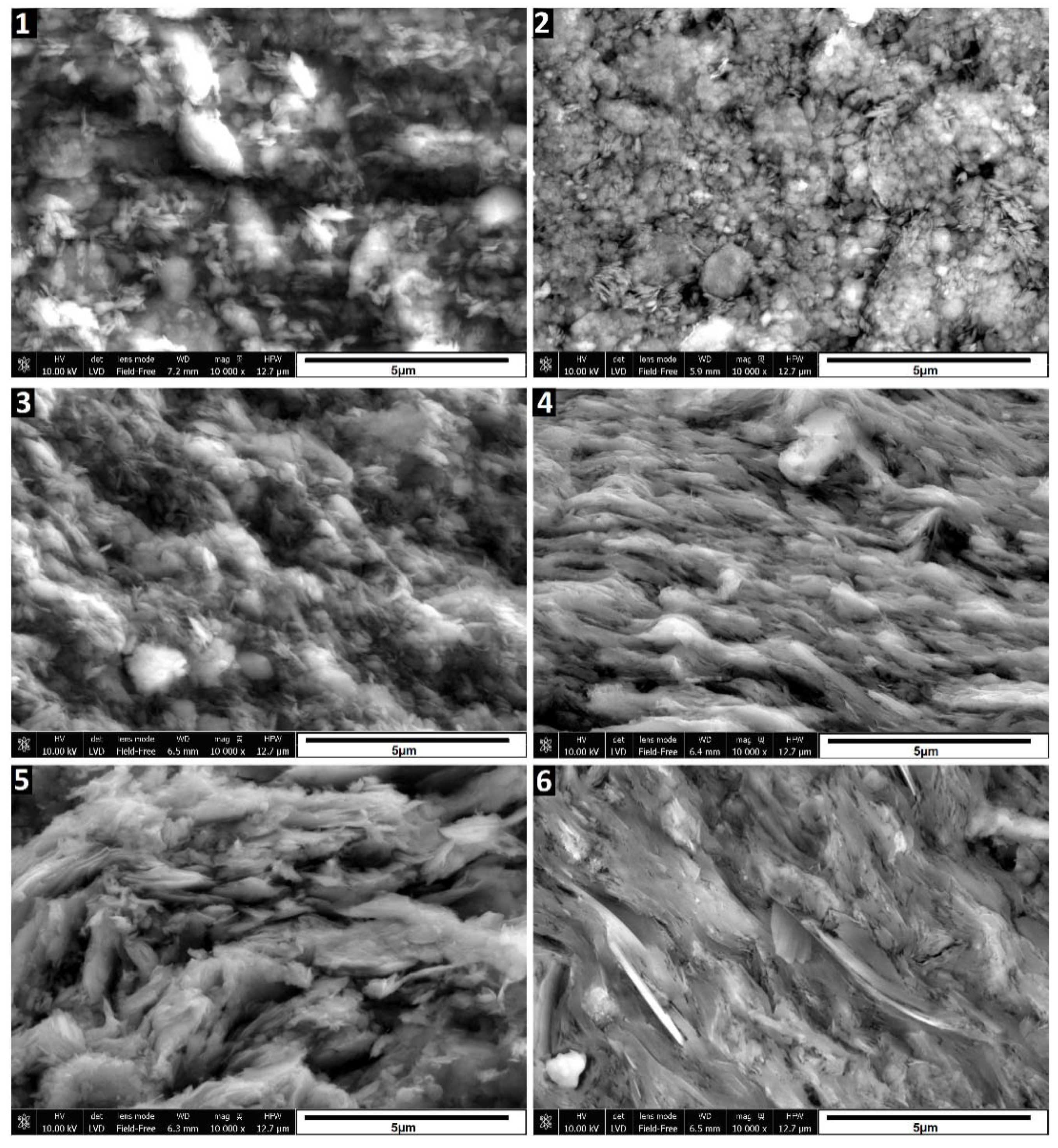
The SEM images in
Figure 3 depict the morphological changes observed in the samples. Sample 2, which underwent calcination at 580°C, exhibits a slight compaction and aggregation of particles compared to the raw sedimented clay fraction (sample 1). However, the changes are relatively subtle. Treatment with 6M and 10M NaOH solutions (samples 3 to 6), particularly when followed by curing at 600°C, induces significant alterations to the illite. Evidence of partial dissolution is observed, manifested by a more rounded nature of illite particles, especially notable in sample 3. In samples 3 and 5, treated with 6M and 10M NaOH and cured at 120°C, respectively, the characteristic layered structure remains visible, and individual particles are distinguishable. However, in samples 4 and 6, subjected to treatment with 6M and 10M NaOH followed by curing at 600°C, the illite particles appear fused, forming a layered structure. These SEM images visually illustrate the changes occurring in the illite structure under different treatment and curing conditions. While XRD data indicates the presence of hydrosodalite, its particles are not identifiable in SEM images, possibly due to their low quantity and poorly crystallized structure formed under these conditions.
Amount of initially formed hydrosodalite appears similar for samples cured at both temperatures, suggesting that most of hydrosodalite forms at 120°C and further temperature increase won’t promote crystallization. Limiting factor here is amount of dissolved clay minerals, which could be improved by using more concentrated alkaline solutions and increasing time where uncured samples are kept in wet condition.
The curing of alkali-treated samples at 600°C in a nitrogen atmosphere was conducted to assess their thermal stability and explore the potential for obtaining new zeolitic phases through the Assembly−Disassembly−Organization−Reassembly (ADOR) process [
32,
33]. This process necessitates the thermal degradation of existing zeolites, and it is more effective in an inert atmosphere [
34].
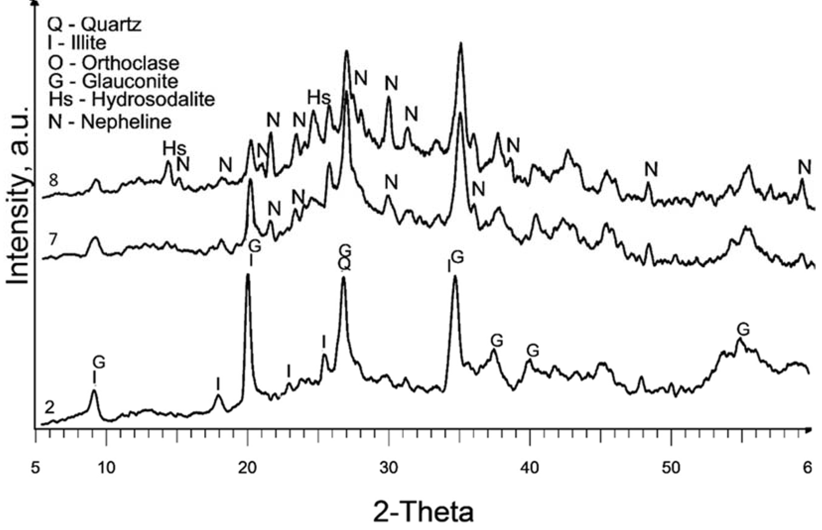
In
Figure 4, the XRD patterns of samples treated in a nitrogen atmosphere at a temperature of 600°C (samples 7 and 8) reveal a significant presence of diffraction peaks corresponding to nepheline. This observation is similar to the XRD pattern of sample 6, which also exhibited the formation of nepheline. The presence of nepheline in these samples indicates that the treatment conditions, specifically curing in a nitrogen atmosphere at a high temperature, promote the formation of this crystalline phase. This suggests that the alteration of the illite during the treatment process and the subsequent high-temperature curing result in the transformation of the illite into nepheline. Most zeolites, including hydrosodalite, at temperatures above 500°C undergo thermal degradation, particularly in an inert atmosphere, leading to the transformation into non-zeolitic phases. Consequently, the properties related to catalytic and adsorption performance of these samples might be inferior due to the low hydrosodalite content and high curing temperature, making this method impractical zeolite synthesis from illite clay. However, this outcome reveals the possibility of synthesizing nepheline from illite clay, which can further be utilized in the production of glass or ceramic products [
35,
36].
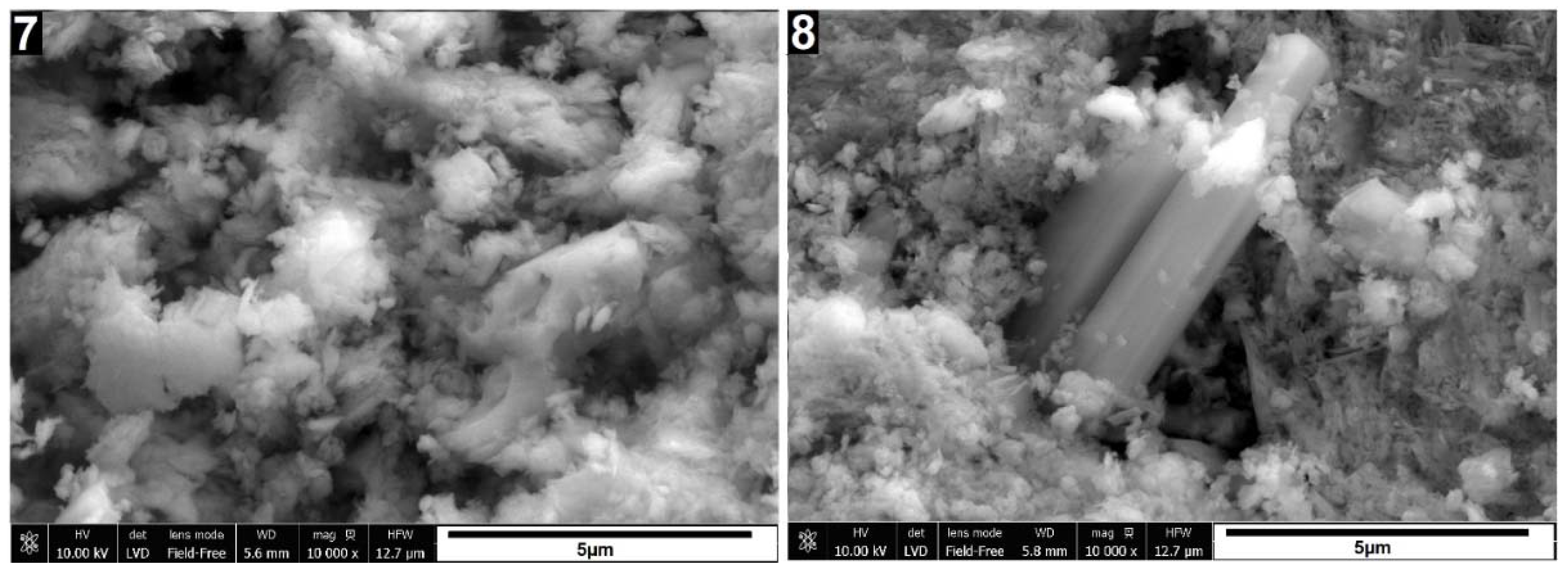
Based on the visual evaluation of the XRD patterns and the SEM image of sample 8 in
Figure 5, it can be concluded that the crystallization of the nepheline phase in the nitrogen environment is indeed more intense and dominant compared to other samples. The well-formed prismatic crystal shape observed in the SEM image of sample 8 further supports this observation.
The nitrogen atmosphere during the curing process seems to promote the nucleation and growth of nepheline crystals, leading to their more pronounced presence in the sample. This suggests that the nitrogen environment plays a crucial role in the crystallization of nepheline and its subsequent formation as a dominant phase in the treated illite clay.
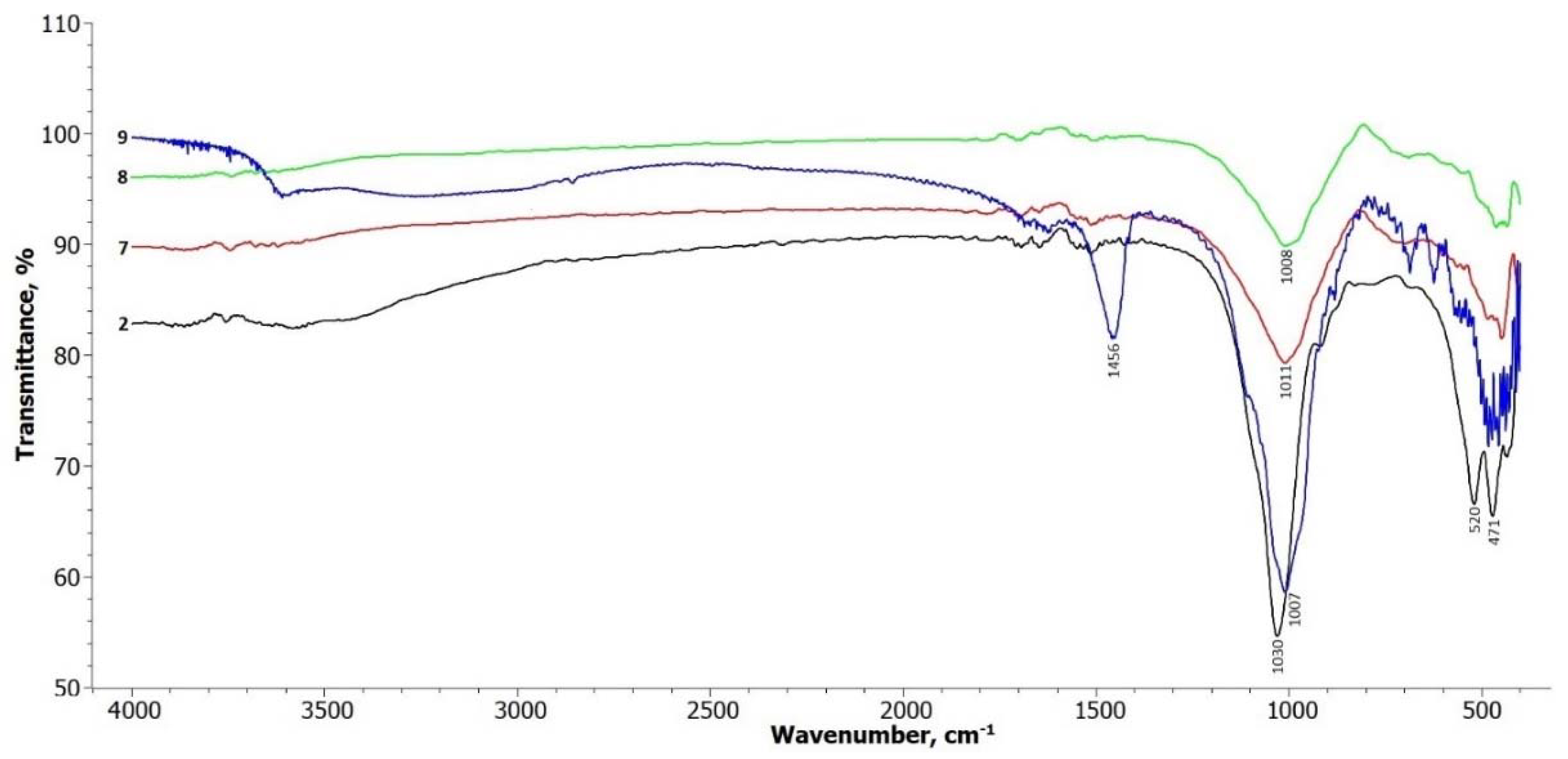
The FTIR spectra of samples 7, 8, and 9 shown in
Figure 6 exhibit similar changes to the spectra of samples 3 to 6. The main change observed is a decrease in the intensity of the vibration at 1030 cm
-1, which corresponds to the Si-O symmetric stretching vibration in the tetrahedral sheet. This suggests a modification or disruption of the tetrahedral structure due to the treatment and curing processes.
The doublet at 520 cm-1 and 470 cm-1, which are typical for the structural functions of alumosilicates (Si-O-Si and Si-O-Al), remains weaker in the treated samples. This indicates a possible alteration in the alumosilicate bonds within the illite structure.
Additionally, new weak doublets in the range of 1650 cm-1 appear in the spectra, suggesting the formation of new bonds, including those involving sodium aluminum silicate. These newly formed bonds may be attributed to the transformation of the illite structure during the treatment process, leading to the formation of different mineral phases.
The FTIR spectrum of hydrothermally treated illite sample 9 shows more pronounced changes compared to the other treatment methods. In the frequency range of 3700 – 3650 cm-1, there is a noticeable alteration in the broad band, as well as a distinct band at 1456 cm-1, which is attributed to zeolite water. This indicates the presence of water molecules associated with the formation of hydrosodalite during the hydrothermal treatment (Gougazeh & Buhl, 2014).
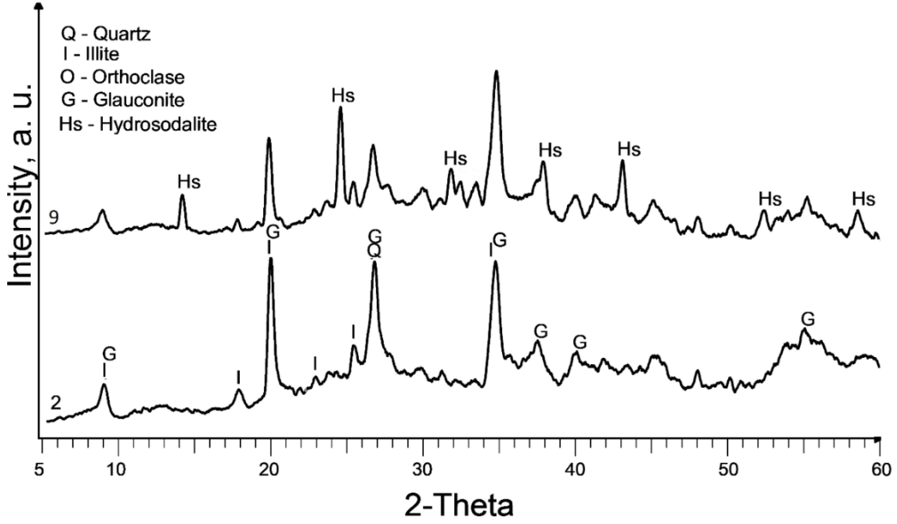
The XRD pattern in
Figure 7 confirms that the hydrothermal treatment leads to the highest crystallinity of hydrosodalite compared to the other treatment methods used in this study. The intense reflexes corresponding to hydrosodalite indicate its complete formation under the conditions of temperature (180°C), pressure (up to 1 MPa), and steam effects during the hydrothermal treatment. The reflexes of the clay minerals illite and illite-glauconite can still be observed, suggesting their persistence in the treated sample.
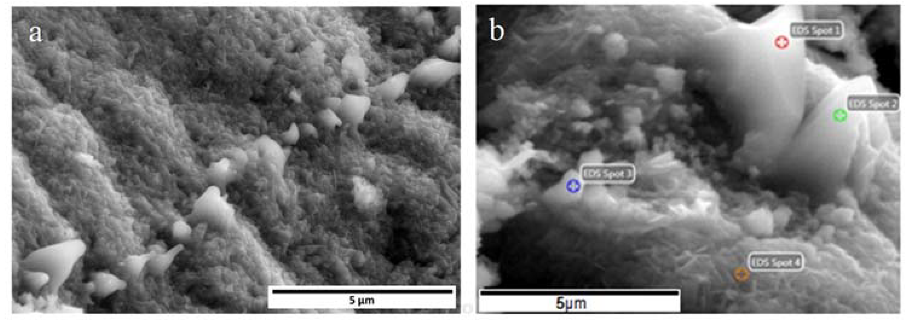
The SEM picture (
Figure 8a) reveals the presence of a ridge of amorphous features alongside the formed hydrosodalite particles. These amorphous formations are likely the result of material "amorphization" caused by the release of steam and pressure during the heating process. The steam and pressure can induce the migration (diffusion) of ions towards the surface of the clay particles, leading to the intensive formation of hydrosodalite. In hydrothermal synthesis, zeolites are formed under elevated temperature and pressure in an aqueous solution. This environment allows for a gradual and uniform growth of zeolite crystals, resulting in improvement in zeolite production. The hydrothermal conditions promote the dissolution of clay minerals and the subsequent reformation into zeolite structures, ensuring a higher level of crystallinity.
The EDS estimated elemental composition of the marked spots in sample 9, as shown in
Table 3. The high percentage of Na (up to 35.99%) observed in the EDS data could be attributed to the excess NaOH that underwent recrystallization. During the sample preparation process, a larger amount of NaOH solution was used to obtain a plastic mass, which might have resulted in an excess of Na available for the formation of hydrosodalite. It is important to note that the excess NaOH can recrystallize and contribute to the higher Na content observed in the EDS analysis.
On the other hand, reducing the concentration of NaOH in the treatment process can lead to a decrease in the dissolved Si and Al from the clay minerals. This reduction in Si and Al availability hinders the formation of hydrosodalite, as these elements are essential components for its formation.
Among the different treatment methods evaluated, the treatment with 10M NaOH followed by hydrothermal treatment appears to be the most favorable for the formation of hydrosodalite. This treatment process not only promotes the formation of hydrosodalite but also preserves the illite-glauconite phase. This retention of the illite-glauconite phase can expand the potential applications of the material.
Additionally, considering significant presence of hydrosodalite, the treatment with 6M NaOH at 120°C (sample 3) should also be noted. This treatment method results in notable changes in the crystallite size, indicating significant structural transformations. While the crystallite size may not be as pronounced as in the case of the 10M NaOH treatment, the 6M NaOH treatment at lower temperature still shows promise for achieving desired modifications. Although the amount of synthesized hydrosodalite appears to be lower, the non-hydrothermal process is less complex, consumes less energy, and reduces potential production costs. Despite the lower content, the samples still retain a notable zeolitic phase presence, making them effective for possible use as adsorbers and catalysts.
The XRD data still reveals significant amounts of illite present after all treatment methods, indicating the challenge of completely dissolving illite. The possible formation of zeolitic phases is significantly impacted by this, as dissolved illite serves as the primary source of Si and Al. However, the retention of high amounts of illite may be beneficial for the catalytic and sorptive properties of the material. It can be considered a composite zeolite-illite-geopolymer material, exhibiting synergistic effects between them. The microporous nature and high surface area of zeolites and illite contribute to catalytic and sorptive properties, while the geopolymeric phase improves the mechanical properties of the material.
The formation process of hydrosodalite from illite-glauconite clay minerals can be described through a schematic diagram as shown in
Figure 9. During the calcination process (step 1), the illite-glauconite clay minerals are subjected to high temperatures, which leads to the removal of chemically bonded OH- groups from the illite structure. This step improves the chemical activity of the clay minerals.
To initiate the formation of hydrosodalite, a NaOH solution is added to the calcined clay minerals (step 2). The NaOH solution reacts with the illite structure, causing it to "dissolve" and release various species including SiO32-and AlO2-. The released species from the illite structure, along with the Na+ and OH- ions from the NaOH solution, undergo rearrangement and form an amorphous gel known as N-A-S-H gel. This gel serves as a precursor for the crystallization of hydrosodalite.
Through the heat treatment process, the amorphous N-A-S-H gel undergoes crystallization (step 3), resulting in the formation of the hydrosodalite structure. The crystallization process allows the gel to transform into well-defined hydrosodalite crystals.
The amount of hydrosodalite produced in this process depends on both the concentration of the NaOH solution and the treatment conditions. Higher concentrations of NaOH, such as 10M, can dissolve more illite, leading to the production of a larger quantity of hydrosodalite. The treatment conditions, including temperature and duration, also play a role in the crystallization and formation of hydrosodalite.
5. Conclusions
In this study, the synthesis of zeolite-hydrosodalite was investigated by subjecting sedimented clay fraction containing raw illite-glauconite clay to alkali-thermal treatment. Effects were explored using 6M and 10M NaOH solutions, as well as different thermal and hydrothermal treatment conditions, to induce the formation of hydrosodalite.
The main phase that forms after alkaline treatment in this study is hydrosodalite (Na8[AlSiO4]6(OH)2∙2H2O). The alkaline treatment involves the use of NaOH solutions, and it was found that a higher concentration of NaOH leads to a significant increase in the formation of hydrosodalite. However, it should be noted that increasing the curing temperature from 120°C to 600°C resulted in a slight decrease in the amount of hydrosodalite formed. This observation was based on changes in the XRD peak intensities. The higher curing temperature led to the crystallization of the nepheline phase, which caused a slight reduction in the amount of hydrosodalite formed. It was observed that samples treated with 6M NaOH and 10M NaOH solutions, followed by curing in a nitrogen environment at 600°C, showed an enhancement of XRD reflexes belonging to nepheline.
In the SEM images, it was observed that the characteristic layered structure of illite-glauconite in samples treated with 6M and 10M NaOH solutions, followed by curing at temperatures of 120°C and 600°C, still retained the layered structure, although it appeared remarkably fused. This indicates that the treatment process and conditions caused some alteration and compaction of the layered structure but did not completely disrupt it. However, in contrast, when these samples were treated at 600°C in a nitrogen environment, the layered structure of illite-glauconite disappeared, and the formation of nepheline was observed. This suggests that the higher temperature and the specific environment of the nitrogen atmosphere led to the transformation of the original illite-glauconite structure into nepheline, resulting in the loss of the characteristic layered structure.
Intensive formation of hydrosodalite was primarily observed in samples subjected to hydrothermal treatment, particularly when combined with a primary treatment using a 10M NaOH solution. Hydrothermal treatment, which involves high temperature (180°C) and pressure (up to 1 MPa), along with the presence of steam, provides favorable conditions for the complete formation and crystallization of hydrosodalite.
Treatment of the sedimented clay fraction with a 6M NaOH solution followed by curing at 120°C in an air environment is noteworthy. The study indicates that this particular treatment condition leads to the formation of hydrosodalite with relatively small crystallite sizes.
Curing the samples in both air and nitrogen environments at 600°C leads to a reduction in hydrosodalite formation. The higher curing temperature of 600°C appears to cause thermal degradation of hydrosodalite, resulting in a decrease in its formation.
