1. Introduction
The modernization of public transportation has become an imperative pursuit due to increasing environmental concerns and need for carbon emissions reduction. In this context, the integration of hydrogen as a clean and renewable energy carrier to fuel transport media emerges as a promising avenue to address these challenges [
1,
2].
Current advancements focus on the use of hydrogen in fuel cell-based hybrid power trains [
3], holding the promise of high efficiency and eco-friendliness. However, the straightforward substitution of current buses fleet (or, at least, the extensive retrofit) seem to pose a big hurdle to transport companies [
4]. Traditional internal combustion engines, known for their robustness, have a long-standing presence supported by extensive service networks. Fuel cell electric vehicles (FCEVs) and hydrogen internal combustion engines (ICEs) are not in direct competition; instead, their development mutually drives the establishment of a common hydrogen infrastructure [
5], including production, transportation, and distribution [
6]. Both technologies share vehicle storage tanks, reinforcing their collaborative advancement. For this reason, the utilization of hydrogen in well-established power train based on ICEs attracts applied research interest [
7]. The exploration of hydrogen’s role in ICE-based public road transport (i.e., buses, coaches) is not merely an exercise in technological curiosity; rather, it is a strategic move toward aligning transportation systems with the broader goals of sustainability.
Regulatory framework
Hydrogen-powered vehicles strongly comply with stringent EU decarbonization goals, highlighting their potential for meeting environmental regulations [
2]. At the EU level, the revised Renewable Directive (RED) sets ambitious targets for the transport sector, namely 14% decrease of CO
2 emissions related to all sub-sectors. Moreover, the new RED III binding targets are amended to 45% on final energy consumption by 2030 and 14.5% for transport [
8]. Nowadays, the carbon intensity of energy usage in the transport sector is around 70 g
CO2/MJ [
9]. International regulation supports technological neutrality. Hence, novel solutions must meet the sustainability criteria set by the EU directive. Compared to the use of standard transport fuels (derived from fossil resources), GHG savings are expected to account for -70% by 2026 in the case of renewable fuels of non-biologic origin (RFNBOs) like H
2 and -65% in the case of biofuels [
8].
1.1. State of the Art: Power-Train Concept Comparison
The use of hydrogen to improve the sustainability of low-haul and heavy-duty transport finds application in different type of power trains (
Table 1): ICE vehicles fueled with fossil fuel products, biofuels, hydrogen or a blend of hydrogen and other fuels, hydrogen FCEVs and battery electric vehicles (BEVs) [
5]. In the first instance, hybrid configurations involving at least two basic technologies are neglected. Research has shown that adding hydrogen to gasoline fueling in spark ignition engines can lead to improved combustion, including a reduction in combustion duration, an increase in indicated thermal efficiency, and a decrease in specific energy consumption [
10]. Additionally, hydrogen combustion can significantly reduce polluting emissions and greenhouse gases [
11]. Furthermore, hydrogen direct injection in ICEs has been found to result in lower NOx emissions, which are one to three orders of magnitude less than those of conventional diesel operation at low load [
12]. However, the high auto-ignition temperature of hydrogen limits the applicability of this combustion mode. Moreover, hydrogen-fueled ICEs have been studied extensively, with research focusing on various aspects such as combustion characteristics, injection methods, and performance optimization [
13]. The results indicate that hydrogen can improve the combustion process due to its wide flammability, low ignition temperature, and high burning speed, leading to better engine performance compared to traditional gasoline-fueled engines. However, it is important to note that abnormal combustion may occur in H
2-fueled engines under anomalous combustion conditions [
14].
Furthermore, the use of hydrogen in ICEs has been recognized as a promising approach from a whole life cycle perspective, indicating a good development prospect for hydrogen-fueled internal combustion engines. Compared to hydrogen FCEV, ICE frequently demonstrate compatibility with lower-grade hydrogen [
15,
16]. For instance, in scenarios where on-site hydrogen production involves methods like either steam methane (fossil o biogenic) reforming with carbon capture and storage or gasification, the produced hydrogen can be directly utilized in hydrogen engines without requiring severe purification. This resilience to impurities is particularly advantageous in the transportation sector, where the shift to high-quality green hydrogen is a gradual process. In particular, electrolytic hydrogen produced with renewable power reaches a high purity level, since in the worst case the electrolyzer outflow is hydrogen with mild contamination of oxygen and water due to gas crossover [
17]. This is an issue for PEM fuel cell based automotive systems, which require a hydrogen purity up to 99.99% [
18], hence required extra hydrogen pre-processing [
19]. Yet, little fractions of oxygen and water are not detrimental for combustion-based process. In addition to that, while considering other green hydrogen production pathways, like the ones based on biogas/biosyngas, the problem of undesired compounds having a negative impact on the end-user is more severe (HCl, H
2S, tars) [
20,
21,
22]. The gas clean-up is mandatory to reach vehicle standards [
21], being ICEs less sensitive to trace contaminants.
Beyond academic research, there are positive signals from the market regarding hydrogen ICE. In December 2021, Toyota showcased an experimental hydrogen ICE vehicle and in June 2022, two manufacturers (SINOTRUK and Weichai) followed up [
23].
1.3. Scope of the Paper
This paper delves into the evolving landscape of advanced fuels, focusing on hydrogen utilization in the context of ICE buses for passenger transportation. After presenting the assessment methodology used, the paper explores the potential performance that can be attained with hydrogen in a real-case scenario against the traditional use of diesel and renewable diesel-fueled ICE buses. The novelty of the paper stands in a simple model that can be replicated in many case-study to assess the suitability of advanced fuels in small heavy duty road transport, where direct electrification seems not appealing and fuel cells are not considered. The case-study compares the envisaged solution from the point of view of primary energy consumption and fuel life cycle GHG emissions (Well-to-wheel). The case study models a 100-km travel mission with the need for frequent stop-and-starts, where fuel consumption is not optimized. The remainder of the paper in organized in three main sections:
Section 2 providing the Assessment methodology,
Section 3 presenting the case-study, and
Section 4 discussing Results.
2. Model and Assessment Methodology
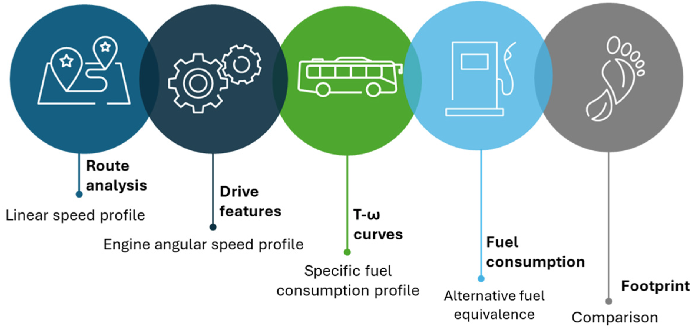
The overarching methodology used for the assessment implements the analysis of typical service routes with drive features, the simplified dynamic modelling of the coach leading to calculation of instantaneous torque and shaft angular speed, the energy requirements and related footprint. A scheme of the workflow is reported in
Figure 1, while details are explained in followings together with data assumed to perform the simulations.
2.1. Mission Load Profile: Route Analysis
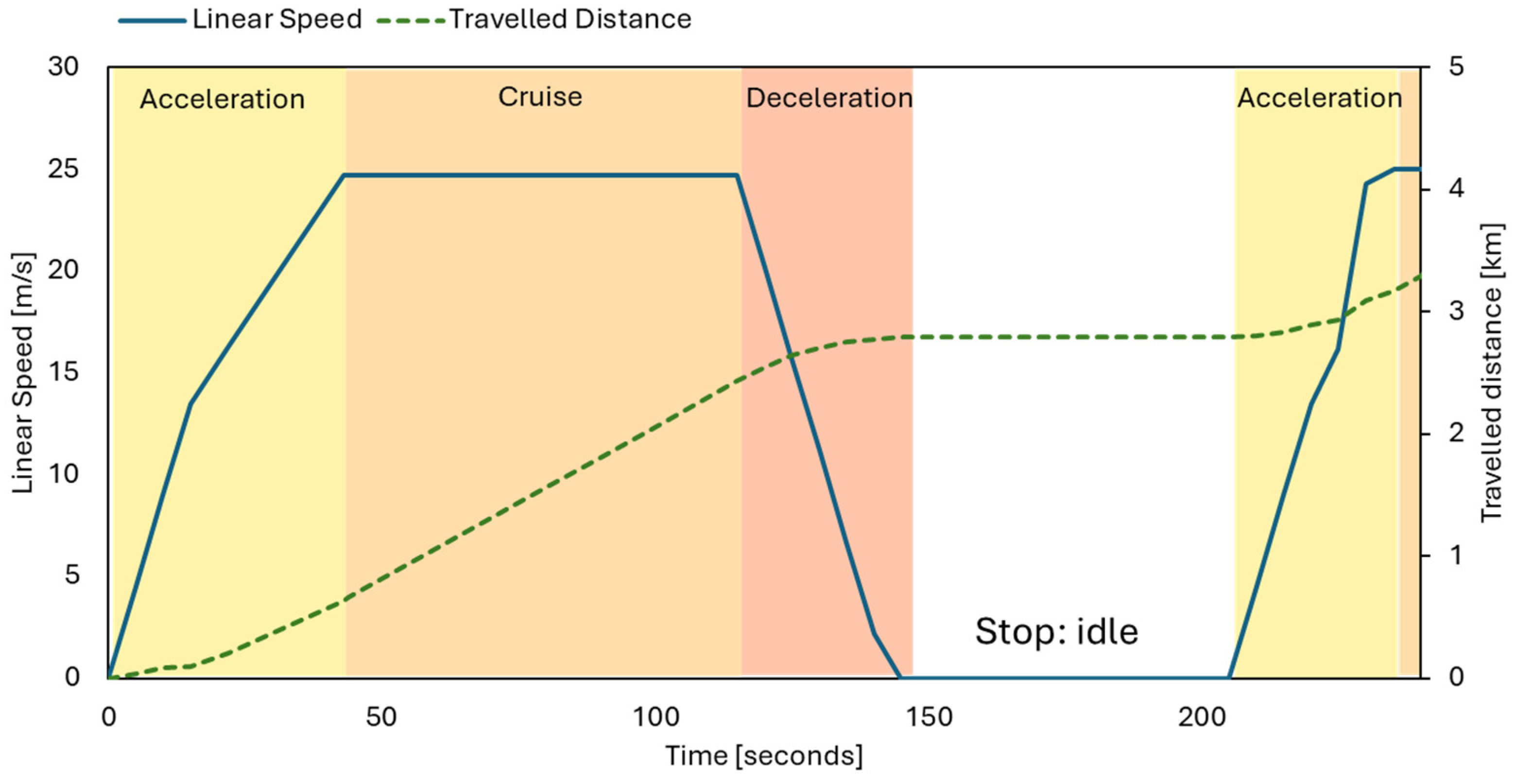
The route is analyzed cosidering the overall length and the distance between stops. A trapezoidal profile is chosen to undertake transients and describe the speed variation between two consecutive simulation steps. The front part of the profile consists of a linear rise of the speed (acceleration) up to a determined value. The steady-state condition lasts for a duration compliant with the travel mission (distance between two consecutive stops of the coach). Then, the trail front represents the deceleration, where the speed linearly decreases to zero when the vehicle needs to stop.
Figure 2.
Simplified transient profile: route analysis method.
Figure 2.
Simplified transient profile: route analysis method.
A literature analysis about coaches suggests reasonable values for the acceleration in the corresponding velocity range [
24] – summarized in
Table 2. The acceleration is assumed 0.9 m/s
2 from 0 to 16.6 m/s (approximately 60 km/h). Above this threshold, the acceleration decreases up to 0.4 m/s
2 until the maximum speed 27.8 m/s is reached corresponding to 100 km/h. In the deceleration operations, the torque on the driving wheel is assumed to be null and the acceleration equal to - 0.9 m/s
2. This means that the deceleration is solely due to the brakes, thus neglecting the engine’s pumping operations.
2.2. Mission Load Profile: Drive Features
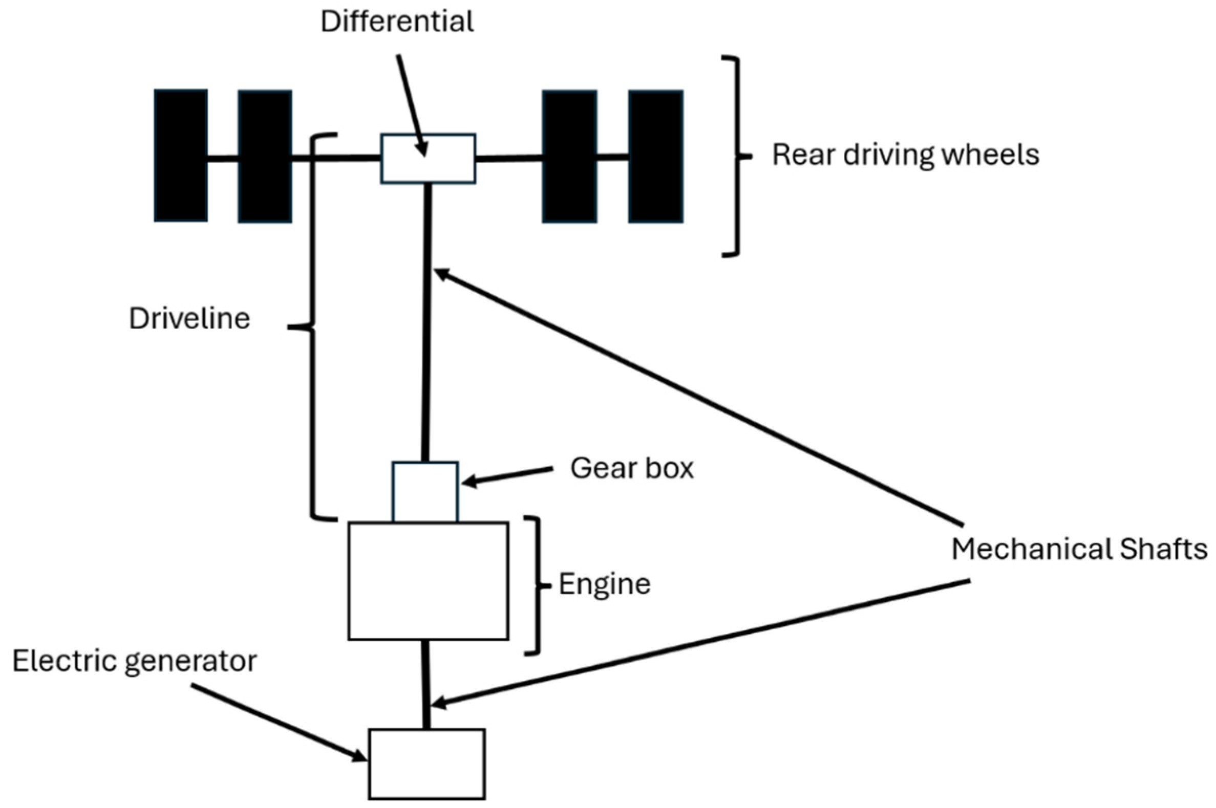
The coach power train and driveline are modeled according to the scheme in
Figure 3, where the engine drives the rear wheels through the mechanical shaft. Moreover, the coach uses an electric generator for the ancillary services. For the sake of this work, the electric generator is assumed to be directly connected with the engine, adjoining an additional load to it. The model and the powertrain assumed for this study also require to consider speed range for each gear (
Table 2).
Figure 3.
Schematization of the powertrain and driveline of the coach.
Figure 3.
Schematization of the powertrain and driveline of the coach.
2.3. Dynamic Coach Model: Torque-Velocity Correlation
The simplified dynamic modelling of the coach consists of the analysis of all forces acting on it during the whole mission. Despite its simplicity, this approach is suitable for predicting fuel consumption by determining the resultant force on the coach as a function of the route slope (). Moreover, the advantage of this methods stands in a small number of input parameters. Then, the model allows to simlate the flexibly of operation in routes featured by frequent start and stops and considerable slopes, whose effect is to increase the total resistance and then the fuel consumption.
In detail, the forces analysed are:
the traction between wheels and the ground (Fm), responsible for the rolling friction and the forces parallel to the direction of the motion given by the velocity vector (v), with a direction (representing the route slope)
the gravity load (P)
the inertial load due to the acceleration of the coach. (Fi)
the aerodynamic friction (D)
the normal reaction force (N).
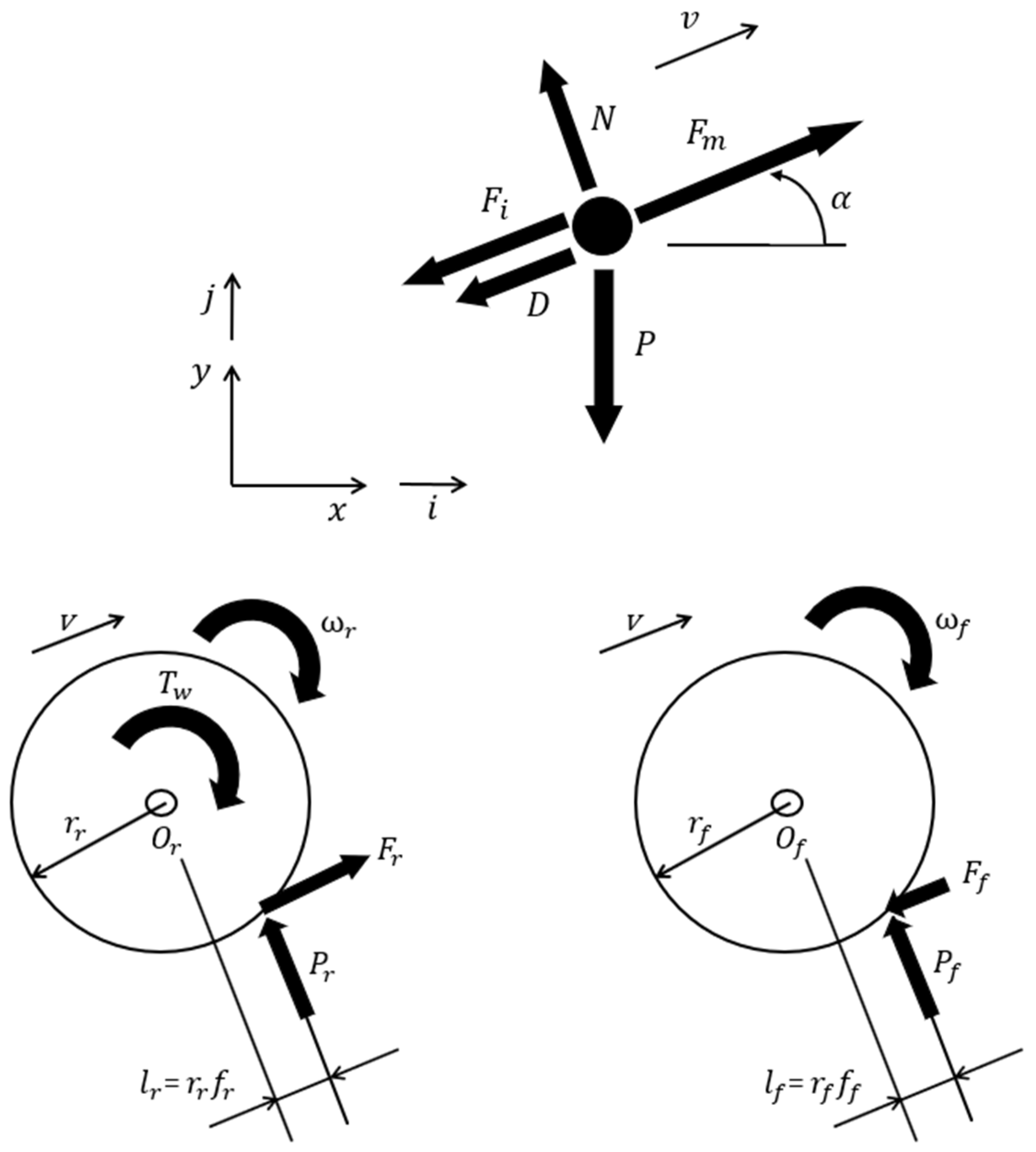
Equation (1) reports the vectorial equation of the particle model of the coach, where Fi, D and N are detailed in Equations (2), (3) and (4) respectively. The force diagram is shown in Figure 4.
Figure 4.
Force diagrams: material point model (left), free body of driving wheels (center) and driven wheels (right) along a sloped path.
Figure 4.
Force diagrams: material point model (left), free body of driving wheels (center) and driven wheels (right) along a sloped path.
Considering the extensive volume and mass of the coach, these forces are applied in different points of actions. Namely, the traction acts on a small area on the tires, thus being considered as a concentrated force in the corresponding point of of contact between the ground and the tire. The inertial and gravitational loads act on the whole volume of the coach, while the aerodynamic friction was distributed on its surface.
As a result, these considerations required knowing the exact position of the application point of every force to obtain the free-body diagram of the coach as well as its geometry, but the lack of such details imposed to model the coach as a material point (Figure 4, left). However, the need to assess the rolling friction on the wheels in the material point model required considering the free body diagram of the coach as an extended body to determine the weight distribution between the front and rear axle. As a result, the weight distribution was considered symmetric between the axles because the engine, transmission system, steering system, and tank were assumed to be located on the chassis in a way that made the weight distribution symmetric between the axles (Figure 3).
This assumption allowed imposing the equilibrium of the moments of all forces and torque that acted on the driving and the driven wheels about their corresponding rotation centers (O
r and O
f, for the rear driving wheel and front driven wheels respectively - see Figure 4, center and right). In Figure 4 center and right, each free body diagram represents the wheels placed on each axle. The forces due to the hinge in the rotation center are not reported because their moments about these points are null. The driving torque (
) contributes to the moment equilibrium of the driving wheels on the rear axle. The inertia of the wheels is neglected because it is assumed to be smaller compared to the whole mass of the coach. The equilibrium of the moments on the wheels determines
and
as in Equation (5) and Equation (6) respectively. The algebraic sum of the components of the forces
and
corresponds with the component of the force
in the material point model - Equation (1). At the same time, the algebraic sum of the components of the vertical forces
and
matches with the component of the vertical force
of the material point model - Equation(7) and Equation (8) in reference to Equation (1).
Therefore, the combination of Equation (5) and Equation (6) with Equation (1) allows expressing the torque on the rear wheels as a dependence of the resistances. In detail, the assumption that front and rear wheels have the same radius
and the same rolling friction coefficient
leads to calculate the torque responsible of the motion of the rear wheels as in Equation (9). The friction coefficient is assumed equal to 0.015. Moreover, the same value of the radius for the rear and forward wheels implies that their angular velocity is the same (
). As a result, the multiplication of the left and right hand sides of Equation (9) by the angular velocity
allows expressing the power provided to the rear wheels (
, as required for the motion of the coach with a linear speed equal to
In addition to the traction power, the ancillary functions add a further load, equal to a net power requirement named
. The efficiency of power conversion is indicated by
. Finally, the resulting power required at the engine (
in which
represents the overall efficiency of the driveline including the gearbox, the shaft and the differential) is given by the sum of the gross share of
and
, corresponding to a total engine torque named
- Equation (12), where the engine angular velocity
is found as the product of the angular velocity of the wheels
and the gear ratio of the whole driveline
. The specific energy consumption of the engine is deducted from literature torque-angular velocity curves, available in the literature for the types of engine under consideration [
25].
2.4. Fuel Consumption Calculation
The assessment of the specific fuel consumption required considering an operating map of engine to depict the organic engine efficiency
as a function of engine rotating speed and torque. As a result, once the lower calorific value
of the fuel was specified, the fuel consumption rate
is found by Equation (13). The set of Eqs. (3)–(9) allowed tracing the power, torque and rotating speed and then to the fuel consumption of the engine by using as inputs the mission profile of the coach, the slope of the the path and the way in which the gear ratio was used. The mission profile was a diagram in which the abscissa axes represented the travel time and the ordinate axes the traveled distance by the coach. In detail, the discretization of the mission profile into several time intervals whose duration was
allowed calculating the fuel consumed in each timestep. As a result, the whole fuel consumption during the mission is found as the sum of each fuel mass consumed in each timestep – Equation (14). Finally, for refence in the following metrics, the fuel consumption is expressed in nornalized terms, as distance-specific fuel consumption, on a mission distance of 100 km – Equation (15). The model presented allow the direct simulation of power and fuel consumption profiles for ICEs running on standard diesel oil (B0) and ICE fuelled with hydrogen. In the followings, the standard diesel propulsion is compared with alternative fuel to diesel oil (B0). In these cases, the energy and carbon footprint metrics will be calculated on equivalent fuel consumption, considering the same energy provision to accomplish the travel mission
– Equation (16).
2.5. Footprint: Comparison Metrics
The propulsion solutions investigated in this paper are compared through the metrics defined in this sub-section. In order to address the environmental impact, the equivalent CO
2 emissions ascribed to a 100-km travel mission are accounted for, considering both Well-to-Tank emissions (
) arising in the fuel production and provision phases - Equation (17) - and Tank-to-Wheel emissions (
) allocated on the fuel direct use - Equation (18). The terms
and
represent the generic fuel’s equivalent CO
2 emission factors specific to the energy used (i.e., g
CO2/MJ
fuel). The overall CO
2 emissions are referred to the Well-to-Wheel cycle, therefore according to the formulation given in Equation (19). Moreover, the solution investigated are compared based on the mission total primary energy consumption (
), adding to the direct primary energy consumption already formulated in Equation16, the primary energy consumption required for the provision of the fuel, as in Equation (20). The coefficient
stands for the energy consumed in the fuel production and provision phase to deliver one unit of energy for the final use.
3. Case-Study
This sections presents the data used to run the simulations, namely referred to the suburban public transport routes (subsection 3.1), coach engine assets and fuel options (subsection 3.2), and the plan of simulations (subsection 3.3).
3.1. Route
The coach run is simulated on a real mission profile, with an overall length of 100 km in which there are 35 stops each lasting 110 s and an average slope of 1.2-1.4%. The detailed slope variation is obtained from the Google Earth [
26] database and implemented in the calculation model presented in
Section 2 (the slope represented the tangent of the route profile as the vertical increase to an horizontal distance of 100 m). The choice related to the simulation scenario appeared suitable to represent a typical road public transport mission with several start and stop intervals and path with several speed values.
3.2. Coach Engines and Fuel Properties
The methodology previously described was employed to predict the fuel consumptions obtained during the mission profile by a coach whose characteristics reflected the ones of a series of commercial coaches suitable for the simulated path. As a result, an analysis of the literature and commercial catalogues appeared mandatory to estimate properly the values representative of the vehicle model (
Table 3).
The calculation of the fuel consumption was performed by considering that the weight of the coach was constant. This simplification appeared plausible because it was precautionary because it neglected the emptying of the tank and considered the same number of passengers. At the same time, the drag coefficient was assumed equal to an average value suitable for the velocity range exhibited in the mission profile [
27].
The engine cases under investigations are reported in
Table 4, with reference to technical datasheets regarding DI compression ignition and DI Spark ignition engine. The baseline fuel option is conventional diesel fuel, referred to fossil resources-based standard fuel production process. As alternatives RFNBOs, synthetic diesel fuels (Synthetic Diesel produced with electrolysis-assisted Fischer Tropsch or Wood Gasification + Carbon Capture and Storage Fischer Tropsch) and biogenic substitutes for fossil diesel are considered. Concerning the latter, Fatty Acid Methyl Ester (FAME) [
28] and Hydrotreated Vegetable oil (HVO) [
29] are included in this assessment. Normally, paraffinic fuels (HVO, GTL, BTL) tend to lower the gravimetric fuel consumption. Conversely, FAME-type fuels increase fuel consumption, even by 15% in the case of neat biodiesel. All fuel properties are recapped in
Table 5, including the equivalence factor, which represented the gravimetric equivalent fuel consumption compared to standard fossil diesel.
3.3. Design of Simulation Cases
The simulation is run under 4 cases, namely DI compression ignition engine fueled with standard diesel B0 (case 0, assumed as baseline for the validation of the proposed methodology), DI compression ignition engine fueled with synthetic diesel (case 1 synthetic diesel produced with electrolytic hydrogen and CO
2 from combustion flue gases, case 2 Fisher Tropsch synthetic diesel from wood gasification syngas coupled with CSS) and bio-diesel (case 3 FAME and case 4 HVO), and finally Spark Ignition engine fueled with hydrogen (case 5). Related GHG emissions are disaggregated in the W-t-T and T-t-W segments. Regarding Hydrogen, the T-t-W phase is carbon neutral, yet the production step brings to not negligible GHG emissions, depending on the process [
31]. Considering hydrogen from an electrolytic pathway, GHG emissions are influenced from electricity carbon intensity [
32]. Therefore, the W-t-T emission factor for hydrogen is referred to the electrolysis processes (average efficiency of 60%) and EU mix for grid CO
2 emissions as reported from energy bulletins related to 2022.
Table 5.
Fuel properties, equivalence factors and CO
2 emissions (Type4 forecast 2025+, from JRC report [
33]). Abbreviations: see the Nomenclature section.
Table 5.
Fuel properties, equivalence factors and CO
2 emissions (Type4 forecast 2025+, from JRC report [
33]). Abbreviations: see the Nomenclature section.
| Case |
Fuels |
LHV
MJ/kg |
gCO2eq/MJfuel
|
gCO2eq/MJfuel
|
MJWtT/MJTtW
|
| 0 |
Fossil Diesel B0 |
42.7 |
69.3 |
76.7 |
0.28 |
| 1 |
Syn. Diesel (e-fuel) |
44.0 |
-42.4 |
74.1 |
1.57 |
| 2 |
Syn. Diesel (FT Wood gas+CCS) |
44.0 |
-133.3 |
74.1 |
1.33 |
| 3 |
FAME (Rapeseed) |
37.1 |
-24.6 |
79.6 |
1.13 |
| 4 |
HVO (Waste cooking oil) |
44.4 |
-355.6 |
74.1 |
0.17 |
| 5 |
Hydrogen (electrolysis, EU electricity mix) |
120.0 |
35.7 |
0 |
0.35 |
4. Results and Discussion
The proposed calculation model required to be validated to assess its reliability in providing accurate results. This reason suggested determining the fuel consumption when the coach performed the mission by employing a commercial DI compression ignition engine fueled with standard diesel oil (B0), as reported in Case 0. After that, the validated simulation profiles were used to assess the impact of alternative diesel-type fuels, as well as applying the model to the case of the hydrogen spark ignition engine.
4.1. Travel Mission Simulation in the Base Case: Results and Validation
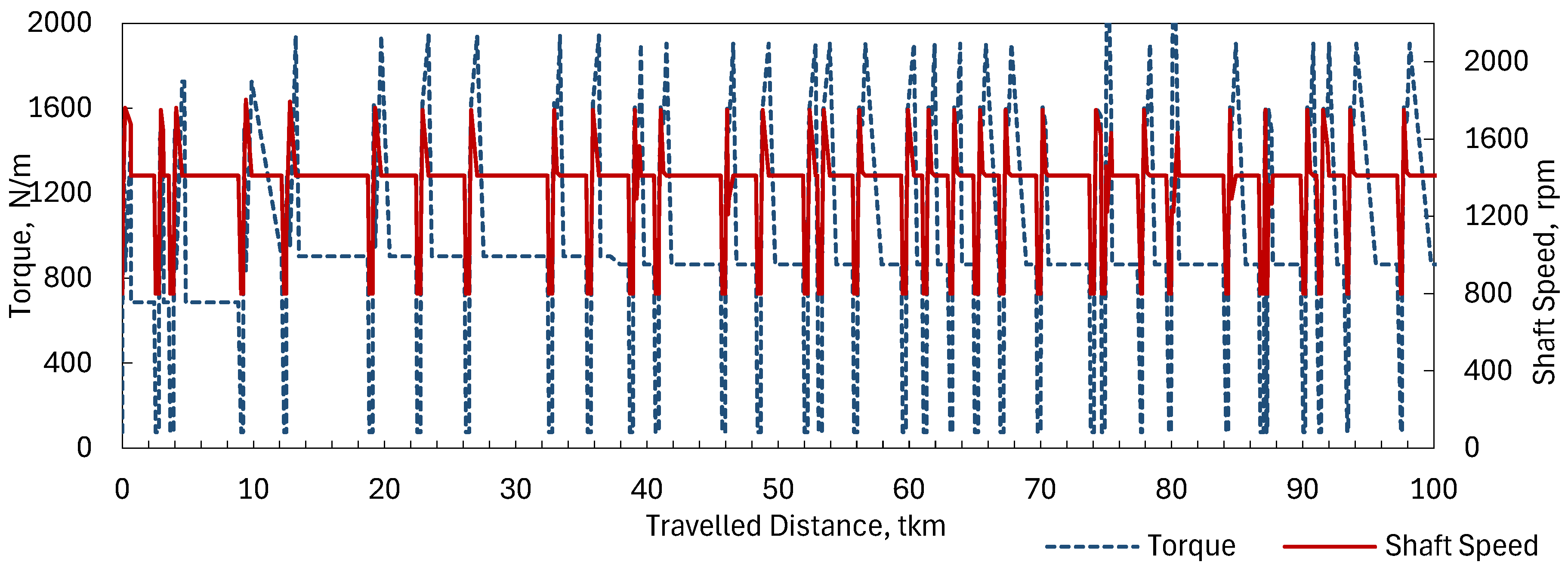
Figure reports the simulation profiles for torque and shaft speed required to accomplish the defined travel mission. The results revealed that the fuel consumption requested by the mission profile was 2.08 km/l for a speed of 41.5 km/h and appeared acceptable in comparison with the references that estimated a fuel consumption between 1.4 and 3.4 km/l. Furthermore, the validation indicated that the maximum power, torque, and rotating speed provided by the engine fell within the limit proposed for this engine since they were about 310 kW, 1950 Nm, and 1800 rpm, respectively. Therefore, these travel profiles obtained for the DI compression ignition engine and validated were taken as reference profiles to evaluate the energy and emission parameters for all alternative fuels.
Figure 5.
Mission profile for the passenger coach: torque and shaft speed vs. travelled distance.
Figure 5.
Mission profile for the passenger coach: torque and shaft speed vs. travelled distance.
4.2. Direct Fuel Consumption
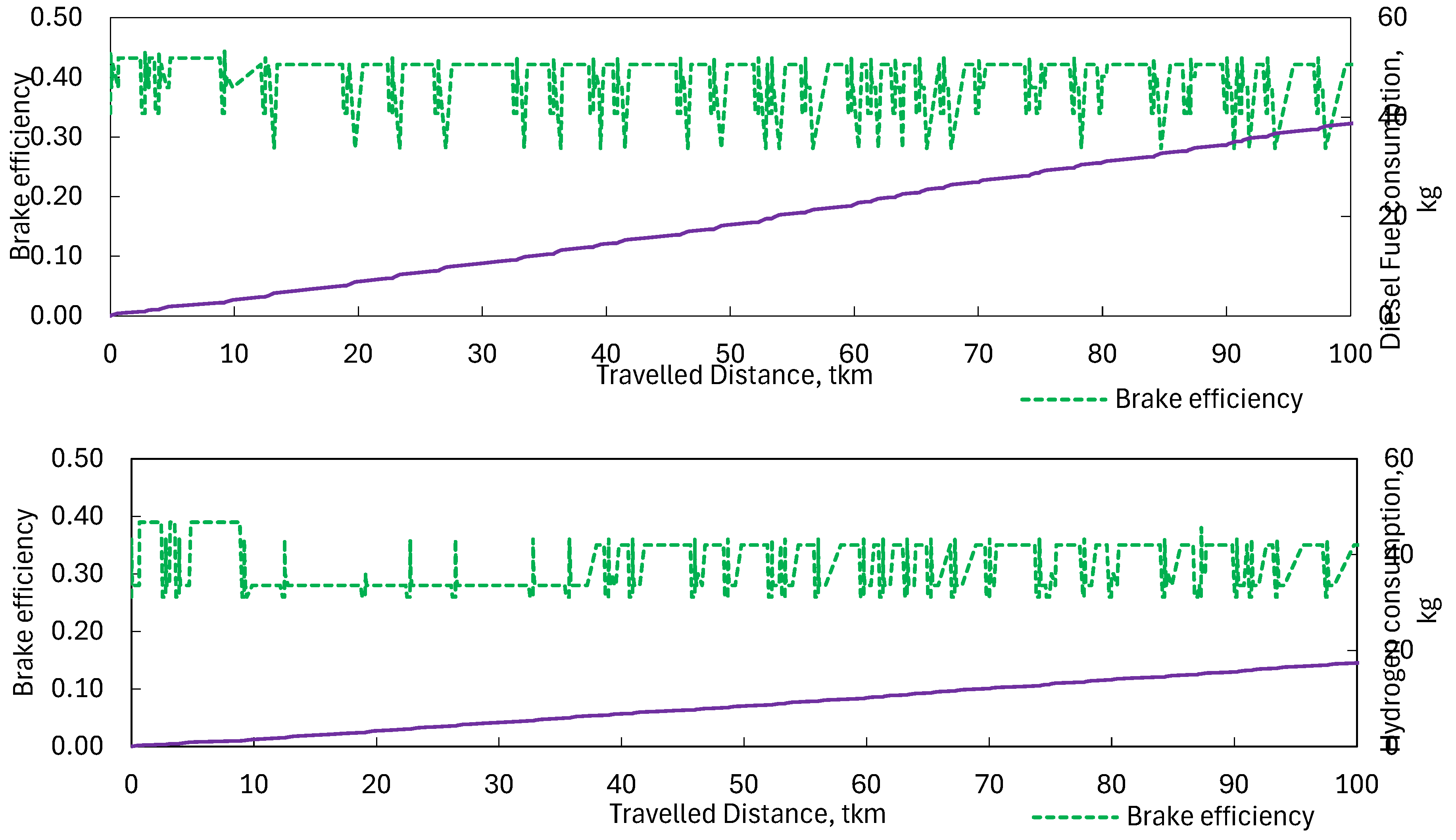
Figure 6 reports the brake efficiency profiles, as well as the integral of the fuel consumption. In the top graph of Figure 6, the brake efficiency and fuel consumption are depicted for the reference DI compression ignition engine. In this case, the 100-km travel mission requires 38.6 kg of standard diesel oil, equivalent to 37.5 kg of synthetic diesel (cases 1 and 2), 44.4 kg of FAME biodiesel (case 3), and 37.1 kg of HVO biodiesel (case 4). Regarding the hydrogen spark ignition engine, the brake efficiency profiles and integral of the fuel consumption are shown in the bottom graph of Figure 6. For this application, the total fuel consumption requires 18.1 kg. The profile for the brake efficiency and subsequent instantaneous fuel consumption are referred to the engine map available at [
25,
26,
27,
28,
29,
30], as previously noted in
Table 4. The integral of the fuel consumption obtained in the two simulation is set as the basis for the Well-to-Wheel energy and emissions assessment discussed in the next sub-section.
Figure 6.
Brake efficiency profile and fuel consumption integral: DI compression ignition diesel-type ICE (top), DI spark ignition Hydrogen ICE (bottom).
Figure 6.
Brake efficiency profile and fuel consumption integral: DI compression ignition diesel-type ICE (top), DI spark ignition Hydrogen ICE (bottom).
4.3. Well-to-Wheel Assessments
The methodology shown in sub-section 2.5 is applied to the cases from
Table 5, based on the direct fuel consumption obtained from the 100-km travel mission simulation.
4.3.1. Primary Energy
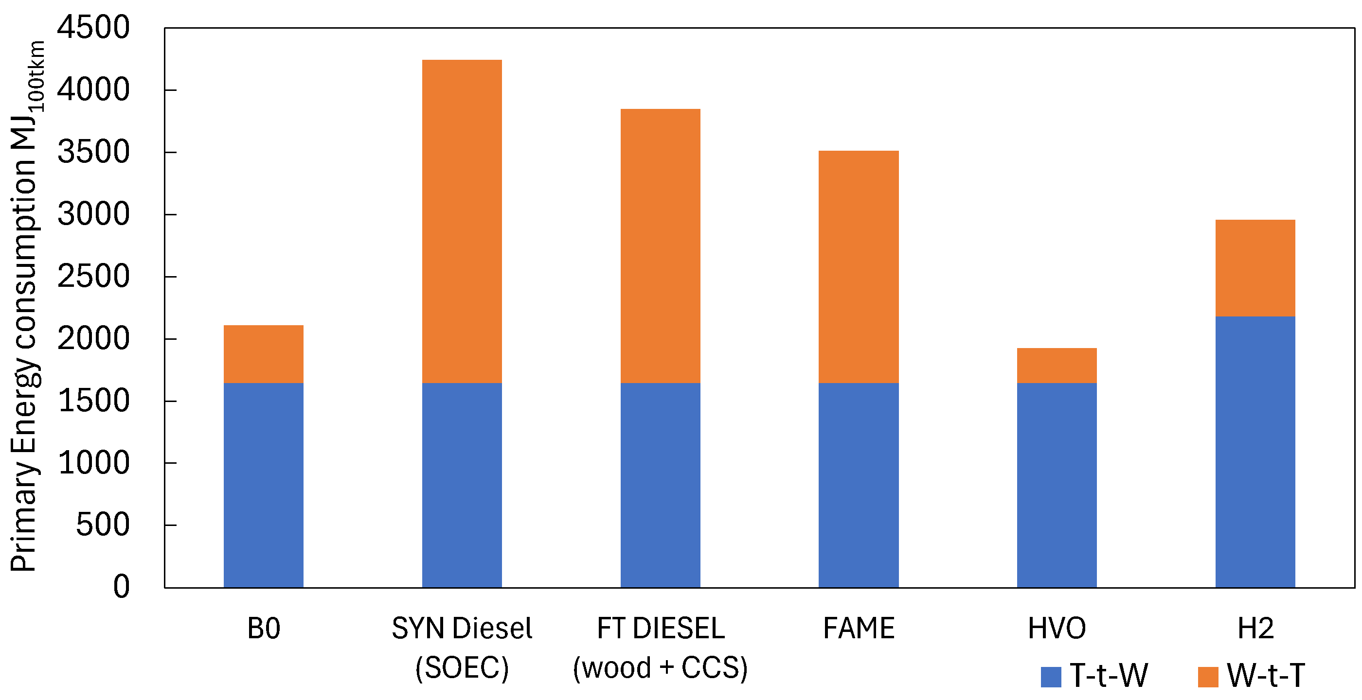
Figure 7 compares the fuels from the point of view of the overall Well-to-Wheel primary energy consumption. In particular, the bar plot reports the primary energy consumption disaggregated into the direct consumption ascribed to the travel mission (in other words the energy related to the fuel consumption of the DI compression ignition ICE for the diesel-type fuels and DI spark ignition hydrogen ICE), and the primary energy consumption necessary upstream the fuel utilization in the coach engine. In Figure 7, the data series is identified as Tank-to-Wheel (T-t-W), likewise the nomenclature used for the emissions computation. This data series reflects the integral of fuel consumption, as already shown in Figure 6. For that all diesel-type fuels have the same indicator, while the hydrogen direct energy consumption is higher, because of the average brake efficiency exhibited in the profile at Figure 6 (bottom). To complete the Well-to-wheel energy assessment, the Well-to-Tank (W-t-T) primary energy consumption is calculated (orange data series from Figure 7) and summed to the previous data series to obtain – see Equation (20). The results show that the primary energy consumption in case 5 (hydrogen) exceeds by 40% case 0 (B0). In addition to the higher primary energy consumption calculated in the direct utilization, electrolytic hydrogen shows a higher κf ration compared to standard diesel (0.35 vs. 0.28). The least primary energy consumption is obtained in case 4 (HVO), where the W-t-T primary emission consumption is lower by -9% compared to the reference case 0. All others diesel-type alternative fuels (case 1, case 2 and case 3) exhibit higher W-t-T primary energy consumption, with mention to synthetic e-fuels (case 1, +101% with regard to reference).
Figure 7.
Weel-to-Whell primary energy consumption comparison.
Figure 7.
Weel-to-Whell primary energy consumption comparison.
4.3.2. GHG Emissions Assessment
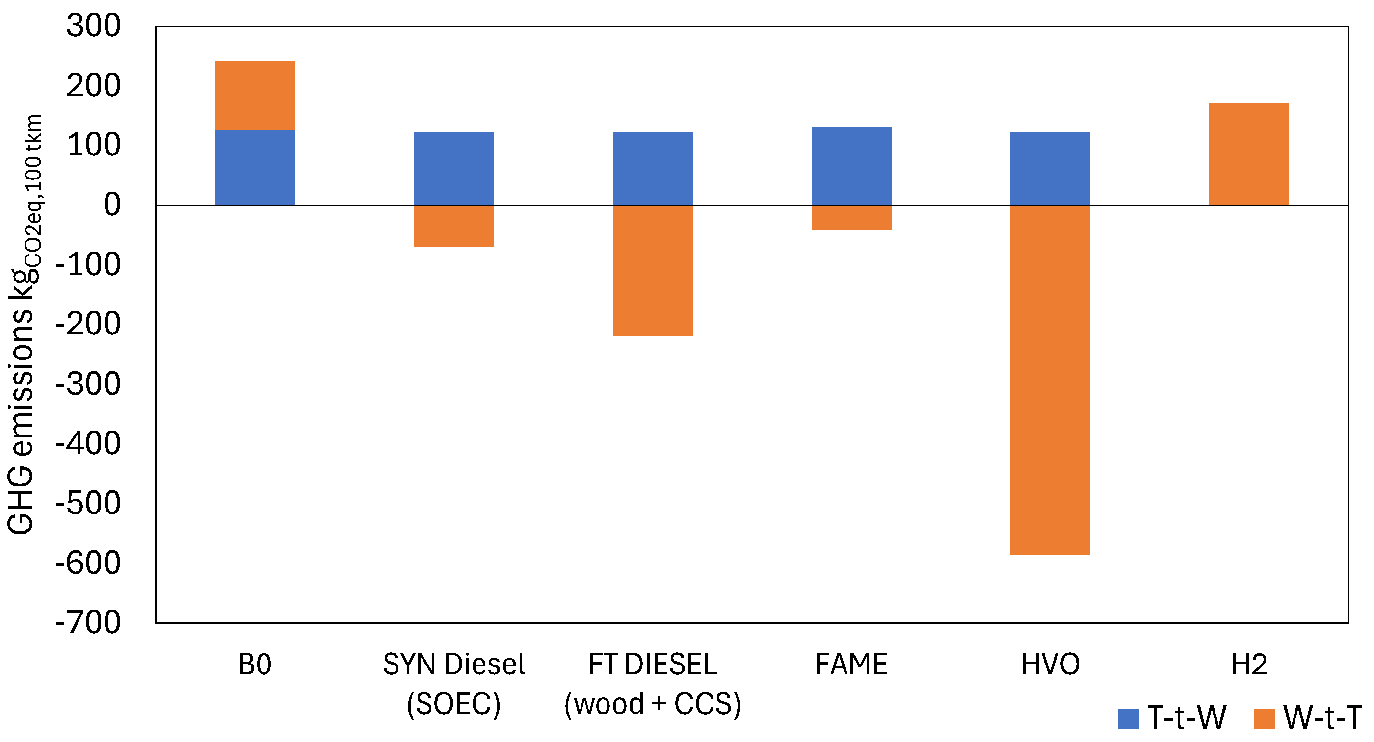
Figure 8 compares the fuels from the point of view of the overall Well-to-Wheel equivalent GHG emissions. The bar plot reports the CO2 emissions specific to the 100-km travel mission, disaggregated into W-t-T and T-t-W emissions.
Figure 8.
Weel-to-Whell equivalent GHG emissions comparison.
Figure 8.
Weel-to-Whell equivalent GHG emissions comparison.
As expected, the reference case 0 shows the higher impact in terms of W-t-W emissions, being both the W-t-T and the T-t-W components positive. Conversely. the alternative diesel-type fuels exhibit negative emissions in the W-t-T phase (namely the production and provision of the fuel). This happens because the alternative fuels of biologic origin (case 2, case 3 and case 4) involve the transformation of biomass, hence a zero or negative balance of carbon, and the RFNBOs (case 1) require CCS to provide CO
2 for synthetic hydrocarbon production [
34]. In particular, the combination of a biological feedstock (wood) with CCS in a FT synthesis process, brings excellent results in terms of CO
2 emission reduction – see case 2. However, the best result for what concerns W-t-W GHG emissions is obtained with HVO, where the final net emission is -464 kg
CO2/
100km (vs. case 0, 240 kg
CO2/
100km). The performances obtained with hydrogen in case 5 are encouraging looking at the direct comparison with case 0, since there are no direct T-t-W CO
2 emissions and moderate W-t-T emissions due to the electric grid residual carbon footprint and electrolysis efficiency (-29% compared to case 0). The W-t-T emissions in case 5 can be eliminated whether hydrogen production is achieved with fully renewable electricity coming from a dedicated power plant. In this ultimate circumstance, hydrogen and synthetic diesel would be convenient against FAME. Nevertheless, the gap between case 4 and case 5 (HVO vs. hydrogen)
5. Conclusions
This work presented a methodology for the simulation of power, efficiency, and fuel consumption profiles for road vehicles, followed by a Well-to-Wheel evaluation of primary energy consumption and equivalent GHG emissions (CO2). The methodology was applied to the case-study of a passenger coach, achieving travel missions with frequent start and stops and considerable road slope. The results obtained were normalized against a travel distance of 100 km. In the same case study two different power trains were evaluated, namely a DI compression ignition ICE for diesel-type fuels, and a DI spark ignition ICE for hydrogen. It is recalled that the travel profiles model non-optimized operating conditions reflecting actual driving needs. The W-t-W energy and emission assessment revealed that hydrogen can compete with standard diesel from the point of view of CO2 emission reduction (-29% in the actual case of electrolysis run with electricity from the EU grid), while it hides a higher primary energy consumption (+40%). For the same mission, among the analyzed alternative fuels, the best results were achieved with HVO, bringing benefits both from the point of view of primary energy consumption (-35%) and emission reduction (464-634 kgCO2/100km avoided).
To conclude, it is worth to mention that the wider implementation of HVO rather than H2 simplifies the vehicles retrofit and the fuel on-board storage, being HVO available in the liquid phase at environmental conditions and having a higher energy density compared to standard diesel. Other results may be found in case-studies featured by different travel missions and different vehicle category.
Author Contributions
Conceptualization, A.B. and M.F.; methodology, A.B. and M.F.; validation, M.A; investigation, A.B. and M.F.; writing—original draft preparation, A.B.; writing—review and editing, M.A.; visualization, A.B. and M.F; supervision, M.A.,, funding acquisition M.A. All authors have read and agreed to the published version of the manuscript.
Funding
This research was funded in the framework of the National Recovery and Resilience Plan (NRRP), Mission 4, Component 2 Investment 1.3 - Call for tender No. 1561 of 11.10.2022 of Ministero dell’Università e della Ricerca (MUR), funded by the European Union – NextGenerationEU. Award Number: Project code PE0000021, Concession Decree No. 1561 of 11.10.2022 adopted by Ministero dell’Università e della Ricerca (MUR), CUP - I53C22001450006, Project title “Network 4 Energy Sustainable Transition – NEST”.
Conflicts of Interest
The authors declare no conflict of interest.
Nomenclature
| BEV |
Battery-Electric Vehicle |
| CCS |
Carbon Capture and Storage |
| DI |
Direct Injection |
| EU |
Europe |
| FAME |
Fatty Acid Methyl Ester |
| FCEV |
Fuel Cell Electric Vehicle |
| FT |
Fisher Tropsch |
| GHG |
Green House Gas |
| HVO |
Hydrotreated Vegetable Oil |
| ICE |
Internal Combustion Engine |
| RED |
Renewable Energy Directive |
| SOEC |
Solid Oxide Cell Electrolyzer |
| T-t-W |
Tank to Wheel |
| W-t-T |
Well to Tank |
| W-t-W |
Well-to-Wheel |
References
- D. Pyza, P. Gołda, and E. Sendek-Matysiak, “Use of hydrogen in public transport systems,” J Clean Prod, vol. 335, p. 130247, Feb. 2022. [CrossRef]
- R. Hren, A. Vujanović, Y. Van Fan, J. J. Klemeš, D. Krajnc, and L. Čuček, “Hydrogen production, storage and transport for renewable energy and chemicals: An environmental footprint assessment,” Renewable and Sustainable Energy Reviews, vol. 173, p. 113113, Mar. 2023. [CrossRef]
- L. Andaloro et al., “Experimental activities on a PEFC based powertrain for a hybrid electric minibus,” Int J Hydrogen Energy, vol. 45, no. 58, pp. 34011–34023, Nov. 2020. [CrossRef]
- A. Rinscheid, D. Rosenbloom, J. Markard, and B. Turnheim, “From terminating to transforming: The role of phase-out in sustainability transitions,” Environ Innov Soc Transit, vol. 41, pp. 27–31, Dec. 2021. [CrossRef]
- International Energy Agency, “Global Hydrogen Review 2022,” 2022.
- M. Genovese, V. Cigolotti, E. Jannelli, and P. Fragiacomo, “Hydrogen Refueling Process: Theory, Modeling, and In-Force Applications,” Energies (Basel), vol. 16, no. 6, p. 2890, Mar. 2023. [CrossRef]
- B. J. Shinde and K. K., “Recent progress in hydrogen fuelled internal combustion engine (H2ICE) – A comprehensive outlook,” Mater Today Proc, vol. 51, pp. 1568–1579, 2022. [CrossRef]
- European Commission, DIRECTIVE (EU) 2023/2413 OF THE EUROPEAN PARLIAMENT AND OF THE COUNCIL. 2023.
- International Energy Agency, “Energy Statistics Data Browser.
- R. Georgescu, C. Pana, N. Negurescu, A. Cernat, C. Nutu, and C. Sandu, “Theoretical and experimental research on the use of hydrogen in the automotive spark ignition engine,” IOP Conf Ser Mater Sci Eng, vol. 1290, no. 1, p. 012010, Sep. 2023. [CrossRef]
- A. Ugurlu, “An emission analysis study of hydrogen powered vehicles,” Int J Hydrogen Energy, vol. 45, no. 50, pp. 26522–26535, Oct. 2020. [CrossRef]
- H. L. Yip et al., “A Review of Hydrogen Direct Injection for Internal Combustion Engines: Towards Carbon-Free Combustion,” Applied Sciences, vol. 9, no. 22, p. 4842, Nov. 2019. [CrossRef]
- Y. Luo and C. Zhao, “An Overview of Pre-ignition of Hydrogen Engine,” J Sci Res Rep, pp. 1–7, Dec. 2020. [CrossRef]
- H. Guo, S. Zhou, J. Zou, and M. Shreka, “A Numerical Investigation on De-NOx Technology and Abnormal Combustion Control for a Hydrogen Engine with EGR System,” Processes, vol. 8, no. 9, p. 1178, Sep. 2020. [CrossRef]
- K. Wróbel, J. Wróbel, W. Tokarz, J. Lach, K. Podsadni, and A. Czerwiński, “Hydrogen Internal Combustion Engine Vehicles: A Review,” Energies (Basel), vol. 15, no. 23, p. 8937, Nov. 2022. [CrossRef]
- Z. Du et al., “A Review of Hydrogen Purification Technologies for Fuel Cell Vehicles,” Catalysts, vol. 11, no. 3, p. 393, Mar. 2021. [CrossRef]
- P. Haug, M. Koj, and T. Turek, “Influence of process conditions on gas purity in alkaline water electrolysis,” Int J Hydrogen Energy, vol. 42, no. 15, pp. 9406–9418, Apr. 2017. [CrossRef]
- T. Taner, “The novel and innovative design with using H2 fuel of PEM fuel cell: Efficiency of thermodynamic analyze,” Fuel, vol. 302, no. May, p. 121109, 2021. [CrossRef]
- Z. Du et al., “A Review of Hydrogen Purification Technologies for Fuel Cell Vehicles,” Catalysts, vol. 11, no. 3, p. 393, Mar. 2021. [CrossRef]
- E. Shayan, V. Zare, and I. Mirzaee, “Hydrogen production from biomass gasification; a theoretical comparison of using different gasification agents,” Energy Convers Manag, vol. 159, no. August 2017, pp. 30–41, 2018. [CrossRef]
- J. Han and H. Kim, “The reduction and control technology of tar during biomass gasification/pyrolysis: An overview,” Renewable and Sustainable Energy Reviews, vol. 12, no. 2, pp. 397–416, Feb. 2008. [CrossRef]
- M. Persson, et al., “Biogas Upgrading To Vehicle Fuel Standards and Grid,” IEA Bioenergy, pp. 1–32, 2007.
- Chinatrucks.com, “China’s First Hydrogen Internal Combustion Engine Powered Heavy Truck.”.
- V. R. Vuchic, Urban Transit Systems and Technology. Wiley, 2007. [CrossRef]
- T. Korn, “The new highly efficient hydrogen internal combustion engine as ideal powertrain for the heavy-duty sector,” 2019, pp. 385–400. [CrossRef]
- “Google Earth,”. Available online: https://www.google.it/intl/it/earth/index.html.
- C. Ç. M. Bayındırlı, “The experimentally and numerically determination of the drag coefficient of a bus model,” International Journal of Automotive Engineering and Technologies, 2018.
- ETIP Bioenergy, “Fatty Acid Methyl Esters (FAME) Fact Sheet.
- ETIP Bioenergy, “Hydrogenated vegetable oil (HVO),” 2020.
- Kulikov, A. Kozlov, A. Terenchenko, and K. Karpukhin, “Comparative Study of Powertrain Hybridization for Heavy-Duty Vehicles Equipped with Diesel and Gas Engines,” Energies (Basel), vol. 13, no. 8, p. 2072, Apr. 2020. [CrossRef]
- M. Wojcieszyk, Y. Kroyan, O. Kaario, and M. Larmi, “Prediction of heavy-duty engine performance for renewable fuels based on fuel property characteristics,” Energy, vol. 285, p. 129494, Dec. 2023. [CrossRef]
- M. Gustafsson, N. Svensson, M. Eklund, J. Dahl Öberg, and A. Vehabovic, “Well-to-wheel greenhouse gas emissions of heavy-duty transports: Influence of electricity carbon intensity,” Transp Res D Transp Environ, vol. 93, p. 102757, Apr. 2021. [CrossRef]
- M. Prussi, M. Yugo, M. Padella, R. Edwards, L. Lonza, and L. De Prada, “JEC Well-to-Tank report v5,” Lexembourg, 2020.
- G. Cinti et al., Integration of Solid Oxide Electrolyzer and Fischer-Tropsch: A sustainable pathway for synthetic fuel, Applied Energy 162, 308-320.
|
Disclaimer/Publisher’s Note: The statements, opinions and data contained in all publications are solely those of the individual author(s) and contributor(s) and not of MDPI and/or the editor(s). MDPI and/or the editor(s) disclaim responsibility for any injury to people or property resulting from any ideas, methods, instructions or products referred to in the content. |
© 2024 by the authors. Licensee MDPI, Basel, Switzerland. This article is an open access article distributed under the terms and conditions of the Creative Commons Attribution (CC BY) license (https://creativecommons.org/licenses/by/4.0/).
