1. Introduction
Production quality monitoring, human motion capture in kinesiology [
1], image caption of highly dynamic science experiments in welding [
2], and vibration analysis of mechanical components [
3,
4] demand extremely-high resolution image caption at high frame rate per second (FPS). Such industrial cameras capture 25 mega-pixel (5120x5120) images at speeds up to 150 FPS generating large amount of data [
5]. Image compression is applied to reduce channel bandwidth and storage requirements. Numerous different approaches have been undertaken [
6] but they can be narrowed down to two types; lossless and lossy. The latter can achieve a higher compression ratio (CR) by dumping some image information and is usually used for web imaging where high speed of transfer and low storage capabilities outweigh the lower level of image detail which is hardly noticeable by the users [
7]. Conversely, no original information is discarded in lossless compression. Typical applications for lossless compression are satellite image transfer [
8], computer vision algorithms and medical imaging [
9] where details are of high importance such as in wireless capsule endoscopy [
10], computer tomography [
11] and magnetic resonance imaging [
12,
13,
14].
Typical implementations of image compression are either software-based or do not employ source data parallelism. The problem of the former is high latency and low maximum throughput achievable on an embedded CPU while the disadvantage of the latter is low processing efficiency. High-speed cameras usually employ field programmable gate array (FPGA) chips as an interface to image sensor and on-the-edge image processing. Due to FPGA’s superiority at parallel tasks we accordingly design our compression algorithm which fully exploits the parallelism from the very beginning on. The image sensor itself generates 128-bit vector representing sixteen consecutive 8-bit pixel values at each clock cycle. Additionally, the algorithm is based on lightweight operations only which enables it to run at a frequency of up to several hundred megahertz. High frequency combined with parallelised processing ensures state-of-the-art throughput of FPGA image compression.
Conventionally, compressed data is clocked out on a single 1-bit output port at an output frequency different from the input frequency. In the usual case of several bits wide input, the output frequency has to be adequately faster than the input one to compensate for the narrower output width, where the exact ratio depends on bit widths ratio and compression efficiency. This approach is favourable because a simple 1-bit FIFO buffer can be used to collect all bits representing compressed data. However, in the case of high-speed continuous compression, where the input frequency is already very high, it becomes unacceptable since achieving an adequately fast output frequency is impossible. Therefore, the output width must match the input width. The main challenge arises from the fact that the bit-width of compressed data is not fixed, as it directly depends on the entropy of the input data and varies with each clock cycle. To address this issue, we propose a novel solution with fixed and identical input and output data widths and clock frequencies. We construct a tree-like concatenation structure with one recursive branch. The recursive branch handles the bits that do not align with the 128-bit output width storing them and re-concatenating them with the next set of output data.
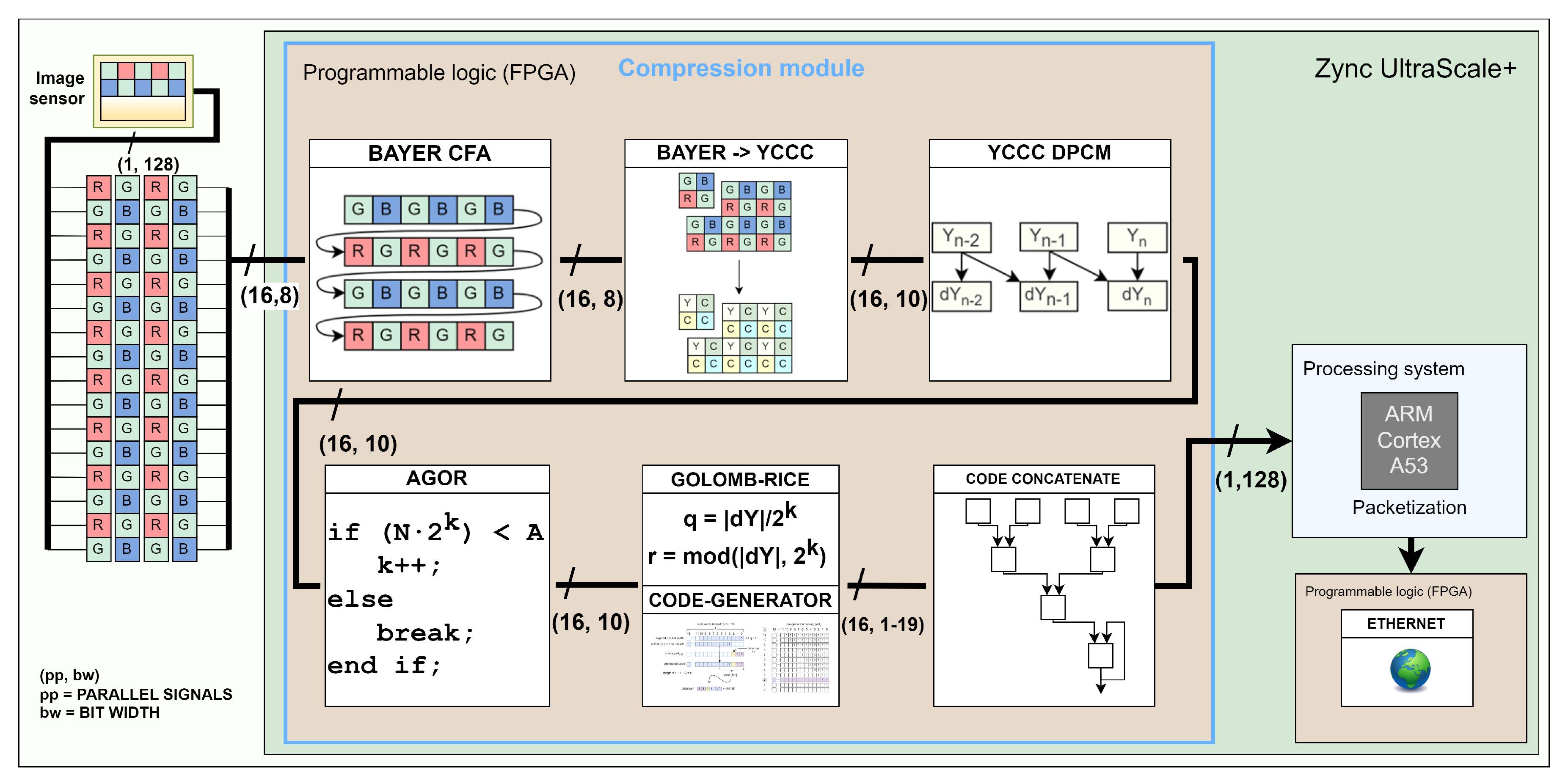
As illustrated by
Figure 1, our compression module interfaces image sensor at the input. At each clock cycle, it receives data in the Bayer colour array [
15] for 16 pixels in parallel. Then, every other row is buffered before the red-green-blue channels are translated to
YCCC colour channels to eliminate colour redundancy. Difference between neighbouring pixels is then used to remove spatial redundancy. In the next stage, we implement adaptive Golomb-Rice encoder (AGOR) for entropy coding. Finally, the generated output codes representing the compressed data are concatenated and stored in the output FIFO registers. The compression module output is connected to the processing system of the Zynq UltraScale+ MPSoC, where packetization is performed in software. The packets are then distributed to the network through hardware Ethernet IP core capable of a 40 Gbit/s link.
The main objective of this work is to develop an algorithm exploiting data parallelism based on lightweight operations for real-time high-resolution image compression. To the best of our knowledge, no research work on continuous real-time parallel image compression has so far been published. In our case of high-speed image capture the proposed compression algorithm can double the streaming frame rate at the same channel bandwidth and decrease memory consumption by half.
In the next section, we present related work on image compression algorithms and implementations. In
Section 3, we explain our solution and present the theory behind it. We then describe the hardware implementation of the algorithm in
Section 4. Finally, in
Section 5, we show our results and compare our work with others.
2. Related Work
There are numerous compression algorithms, but most of them are software-oriented and therefore costly to implement in hardware in terms of area, power consumption and maximum achievable frequency. Some conventional compression algorithms are based on complex mathematical operations, such as the discrete cosine transform in JPEG [
16] or the discrete wavelet transform in JPEG-2000 [
17]. The algorithms, which require large memory blocks and complex operators, are not optimal for an embedded implementation in programmable logic.
The standard for portable network graphics (PNG) [
18] is based on DEFLATE compression [
19], Lempel-Ziv-Welch compression and Huffman coding, in which the dictionary is built up dynamically [
20]. Alternatively, static Huffman coding can also be used, which requires information about the probability distribution of the source symbols. The problem with such coding schemes is that they rely on a dictionary, which increases memory consumption and the amount of data to be transferred, or require a prior statistical analysis of the target mapping. This is why Golomb-Rice coding gained acceptance as it does not require a dictionary and at the same time offers a competitive compression rate.
An alternative approach to the above-mentioned prediction methods are learned compression methods. In [
21], a neural network was trained to learn the probability distribution of pixels and use this knowledge for compression. Although a high CR can be achieved, the presented neural network includes 59K parameters, which occupy a significant amount of the available fast-access memory in a possible implementation on an FPGA device. Furthermore, the compression time is 80 ms for a 64x64 image which is far too slow for high-speed high-resolution cameras.
A series of articles [
22,
23,
24] presented the parallel implementation of lossy compression algorithms such as JPEG and DXT on graphics processing units (GPU). The maximum reported throughput rate was 1385 Mpix/s on an NVIDIA GTX 580 [
25] with a typical power consumption of several hundred watts. Since high-resolution high-speed cameras, such as 25 mega-pixel Smilodon [
5], at 150 FPS generate data at a rate of up to 4 Gpix/s, this only underscores the appropriateness of using an FPGA that can match the throughput of the image sensor for real-time compression at significantly lower power consumption. The Consultative Committee for Space Data System (CCSDS) has published a standard CCSDS 123.0-B-1 [
26] for lossless compression of multispectral images. It was developed with a view to a hardware implementation that contains only light operations. Nevertheless, a complete implementation covering all possible configuration parameters quickly becomes quite complex. This is the main reason why in the work of [
27,
28,
29] the maximum throughput rates were a few Gbit/s with the best performance achieved in [
30] at 12 Gbit/s when compressing five spectral images in parallel.
Some low-complexity algorithms [
31,
32,
33,
34] have been proposed for wireless capsule endoscopy applications, but they generally do not utilise parallelism which can significantly increase throughput. Other works [
35,
36] present parallel compression but generate encoding information data, i.e. additional bits to specify whether sections of generated bitstream are encoded or not. In their particular use case of CPU compressed memory, this was appropriate because the encoding bits were immediately available to the decoder, which was implemented in the same hardware as the encoder. However, this cannot be applied to applications where image compression and decompression are spatially and temporally separated and therefore need to be independent of each other. In standard applications for image transmission and storage, the additional coding bits must be included in the transmitted data, which effectively reduces the compression ratio.
Fowers et al. [
37] proposed an FPGA implementation of a compression algorithm based on the DEFLATE method that exploits the parallelism of the input data . Their framework was scalable to 8, 16, 24 and 32 parallel input bytes. Similar to our work, they also faced the problem of variable output codeword width. Nevertheless, their implementation turned out to be quite complex, which is why they achieved a maximum frequency of only 175 MHz on a Stratix V FPGA device. Due to the parallelism, the throughput was a commendable
with 16 parallel pixels, which is not enough for some high-speed high-resolution cameras that generate image data at rates of
.
The contribution of this work is to bridge the gap in the parallel implementation of real-time image compression while ensuring competitive CR in high-resolution images. An innovative solution is proposed to ensure high throughput compression without additional coding data or a dictionary.
3. Proposed Architecture
An effective approach to image compression is the
compression-first method, in which an image in its raw
Bayer Colour Filter Array state (
Figure 2) is compressed before the demosaicing process. Instead, the latter is performed after decompression on the client side. This prevents a triple expansion of the data before compression even begins. The image is compressed by removing colour and spatial redundancy. Finally, the pixel data is entropy encoded using adaptive Golomb-Rice coding, where the coding coefficient
k is dynamically adjusted based on the data statistics. The parallel output codes are concatenated to form a compressed image bit stream.
The algorithm is divided into four parts: input data composition, colour transformation, differential pulse code modulation (DPCM) and adaptive Golomb-Rice coding. The colour transformation of the Bayer CFA red-green-blue (RGB) image into Y-Cd-Cm-Co (YCCC) channels is used to eliminate colour redundancy. Differential pulse code modulation (DPCM) is used to remove spatial redundancy. In the next part, the coding parameters are calculated and binary codes are generated using adaptive Golomb-Rice coding (AGOR). In the last part, the codes representing the encoded values of 16 parallel pixels are concatenated to generate the final bitstream.
3.1. Parallel Pixel Data Supply
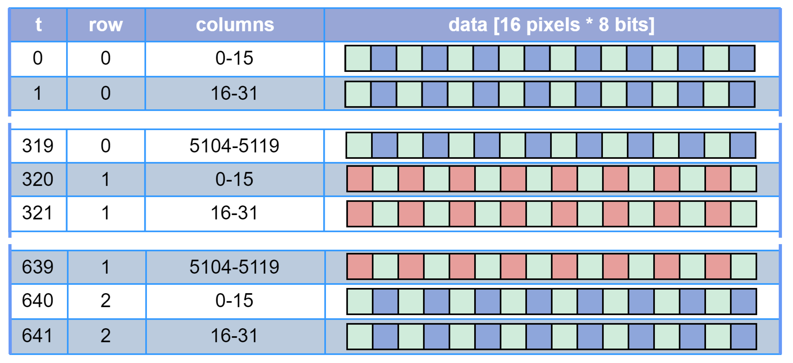
The image sensor interface is often implemented in FPGA devices. The high-speed pixel data bus consists of LVDS (Low Voltage Differential Signaling) connections that provide parallel pixel data. In our case, the data is delivered at each clock cycle from the image sensor as a 128-bit vector representing sixteen 8-bit pixels in a raster scan sequence for a Bayer CFA image as in
Figure 3. The next processing stage requires
bayer elements which consist of neighbouring
R, Gr, B and
Gb pixels. Therefore, the top row is buffered first, and only when the data for the second row is supplied are the complete Bayer elements assembled (
Figure 4). Buffering is realised with FIFO registers. We keep the latency low by performing compression in real time, i.e. as soon as new data is available from the image sensor, it is processed and discarded immediately. Note that in general the number of pixels compressed in parallel in each clock cycle does not have to be fixed at 16, but is scalable and only limited by the available hardware on the FPGA.
3.2. Colour Transformation
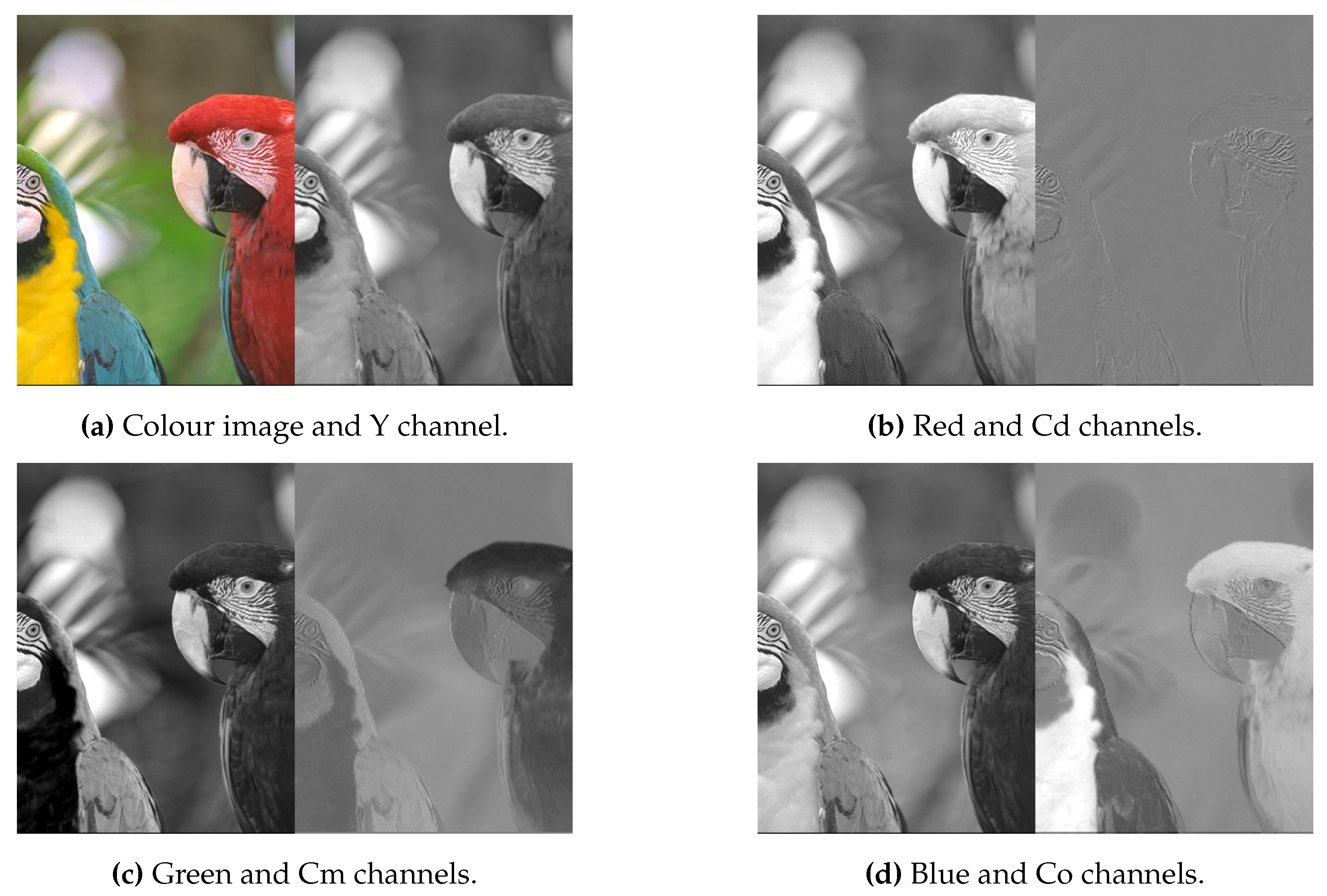
Each colour channel in RGB space contains repetitive, i.e. redundant information, as can be seen in
Figure 5. The redundant data can be removed by colour conversion to another colour space in which the secondary channels contain much less information, as shown in
Figure 5. We used the colour space proposed in [
31]. They analysed different colour spaces, which are relatively cheap in terms of computational cost and found that the Y-Cd-Cm-Co colour space achieves the best CR. We also optimise the translation matrices defined in (
1) and (
2). The Bayer CFA to YCCC translation is calculated by addition and subtraction only, which means that no multiplication hardware is used.
3.3. Differential Pulse Code Modulation
The majority of the image content, such as the background and uniform areas, usually contains only a few details. The pixels values are very similar in these areas, so the same information is repeated in several pixels, which is called spatial redundancy. Therefore, it makes sense to predict the next pixel value and then encode only the difference
between the predicted
and the actual value
x. This method is known as differential pulse code modulation (DPCM).
If the predictions are good, the differences are small, and even approach zero. The prediction can be based on any combination of previous neighbouring pixels. To keep complexity and memory requirements low, a single adjacent predecessor is used as a prediction in this work.
The exception is the first column where predictions are based on a first pixel of preceding row.
The other exception is the very first pixel of the image (seed pixel) for which the predicted value is zero.
3.4. Golomb-Rice Encoding
The DPCM step converts the random distribution (
Figure 6) of the symbols into a Laplace distribution that peaks at 0 (
Figure 6). Equation
6 is used to convert difference values to non-negative values to obtain an exponentially decreasing distribution, as shown in
Figure 6
This new exponentially decreasing distribution fits well with the universal coding sytems that are based on such an assumption. They encode smaller values (which also occur more frequently, as in
Figure 6) with fewer bits and thus compress the information. One of these is Golomb-Rice coding, which is defined in (
7) and (
8). The value
q represents a rounded down quotient between the coding value and a constant
. It essentially indicatess how often the constant can fit into the coding value. The value
r is the remainder of the previous integer division, effectively realised with the modulo operator. Both calculations can be implemented cost-effectively in hardware using bit shifting (symbolised by ≫), bit slicing (symbolised by
) and masking operations. The Golomb-Rice code is composed by concatenating
q consecutive ’1’ bits, the delimiter bit ’0’ and
r represented by
k bits (
9).
3.5. Adaptive Golomb-Rice Encoding
Golomb-Rice coding has a parameter
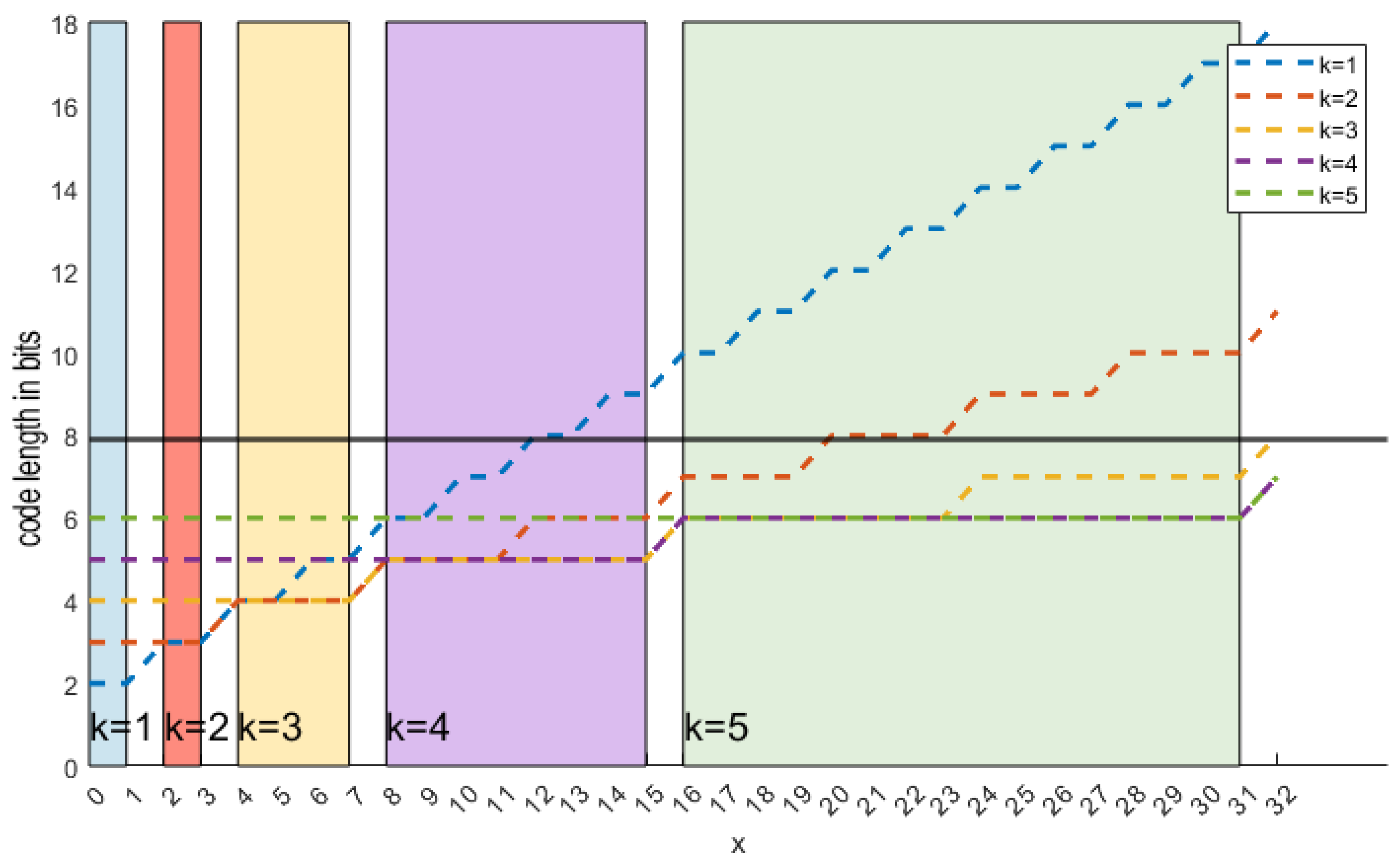
k that determines how the code length scales. Since the code is composed of
q bits, a delimiter bit and
k remaining bits, the total length is defined by (
10) and shown in
Figure 7. A small
k value is suitable for small values of
x while a large
k is better for large
x. One is tempted to dynamically adjust the Golomb-Rice encoder (AGOR) based on the value to be encoded. Based on (
10), we make two propositions.
Proposition 1. For a given value x from the interval , choose . Then corresponding code is the shortest of all possible codes .
Proposition 2. An encoding scheme based on the rule from the Proposition 1 generates the shortest code for each encoding value . The resulting bitstream is therefore the shortest possible and achievis the highest CR theoretically possible as defined by the standard entropy equation.
However, this
ideally computed bitstream cannot be decoded due to a problem similar to the
chicken or the egg paradox; the initially encoded value must be known in order to select
k which is in turn is needed to decode initially encoded value. Therefore, in this implementation, the
k for the
sample is calculated based on the moving average of the
samples as described in Algorithm 1[
39,
40]. In the hardware, the first for loop (line 1) is implemented in parallel, while the third for loop (line 8) is pipelined via
successive modules, each of which contains an
if statement. The parameter
is chosen as the largest
k that still satisfies
, i.e. the unary part is at least 1 bit wide. Conversely, a case with
means that the value only has to be coded in the remainder of the Golomb-Rice code. This is exploited in the case of a seed pixel by setting the
k parameter to
, which is 11 for input width of 8 bits. This effectively results in a seed pixel being encoded in a two’s complement representation.
|
Algorithm 1:Dynamically adjustable parameter k |
- 1:
for channel in [Y,Cd,Cm,Co] do: - 2:
- 3:
- 4:
- 5:
- 6:
for pixel in length(channel) do
- 7:
- 8:
for do
- 9:
if then
- 10:
- 11:
else
- 12:
- 13:
end if
- 14:
end for
- 15:
- 16:
- 17:
if then
- 18:
- 19:
- 20:
end if
- 21:
end for
- 22:
end for |
3.6. Code Length Limiting
If
is large and the parameter
k is small, the quotient
q from (
7) becomes large, which leads to a large code length
l (Equation
10). This happens in a checkerboard pattern, as
k becomes very small in uniform areas while
can be large at the black-white border between two squares. Untreated, such an image can generate codes with a width of up to 2040 bits, which means that an originally 8-bit wide pixel code is expanded by more than 250 times. In a system with 16 parallel pixels, the concatenated code could be up to 16320 bits wide. We solve the problem by limiting the maximum length of the unary parts to 8, resulting in a code defined in the second condition for (
9). If the value
q is greater than 8, the positive value
is coded with 11 bits in two’s complement, i.e. we switch from Golomb-Rice coding to two’s complement coding. With this rule, we limit the maximum permissible code length to 19. The identifier for this coding change is 8 consecutive ’1’s, which are immediately followed by
in two’s complement.
3.7. Bitstream Generation
Typically, a compression algorithm outputs encoded data by outputting a sequence of bits in a serial bitstream. This parallel-serial system can become saturated if the serial output data is not output at a sufficiently high rate, e.g. for a system with 8-bit input data and 1-bit output, the output clock must be at least eight times higher than the input clock. However, in a system with multiple input data sets and a and high input frequency, the output frequency cannot be increased appropriately. Instead of increasing the output frequency, the bitstream can also be output in parallel. However, this leads to problems such as assigning a variable-length bitstream to a fixed-width output port, which requires an efficient buffer architecture. The variable length output problem arises from the fact that the algorithm compresses the full-width input code to a narrower representation. The actual amount of compression changes dynamically and depends on the actual data.
The intensity of each pixel is coded with 8 bits in two’s complement. Then the total width of the input data is wide, where P is the number of pixels supplied in parallel. In our case, we have set , but it can easily be parameterised. After compression, the bitstream should be shorter, i.e. consisting from less bits than the initial bitstream. This means that each pixel is encoded with less than 8 bits on average. While the input to the algorithm is a 128-bit wide input vector representing 16 parallel pixels, the output width is less than 128 bits due to compression and has an unknown length. However, the output port width is fixed at 128 bits to ensure compatibility with other external IPs. It is possible that there are not enough bits () generated for a valid output at every clock cycle due to data compression. On the other hand, even with code length limiting feature there can be up to bits generated in a single clock cycle for the edge cases, i.e. a checkerboard. Since other hardware, such as the transmit module, requires fixed length inputs, the output of the compression algorithm must be aligned to 128 bits.
Other works propose sequential calculation of indices and the sequential concatenation of codes [
41]. However, due to the high complexity of the index calculation, these methods lead to a large propagation delay, which considerably limits the maximum achievable frequency, and are only suitable for non-parallelized compression.
4. Implementation
The algorithm is first developed and verified in C++ and only then implemented in hardware using VHDL. As the algorithm is designed for low complexity and there are no restrictions on efficiency and parallelism in the software model, the C++ implementation is relatively simple. In the hardware implementation, however, additional requirements were added with regard to memory consumption, parallelism, low propagation delay (propagation delay as a function of the complexity of a sub-algorithm), dynamically adjustable ranges, the generation and concatenation of vectors of variable length and finally the output of a bitstream of variable length via an output port with a fixed width.
4.1. Parallelism
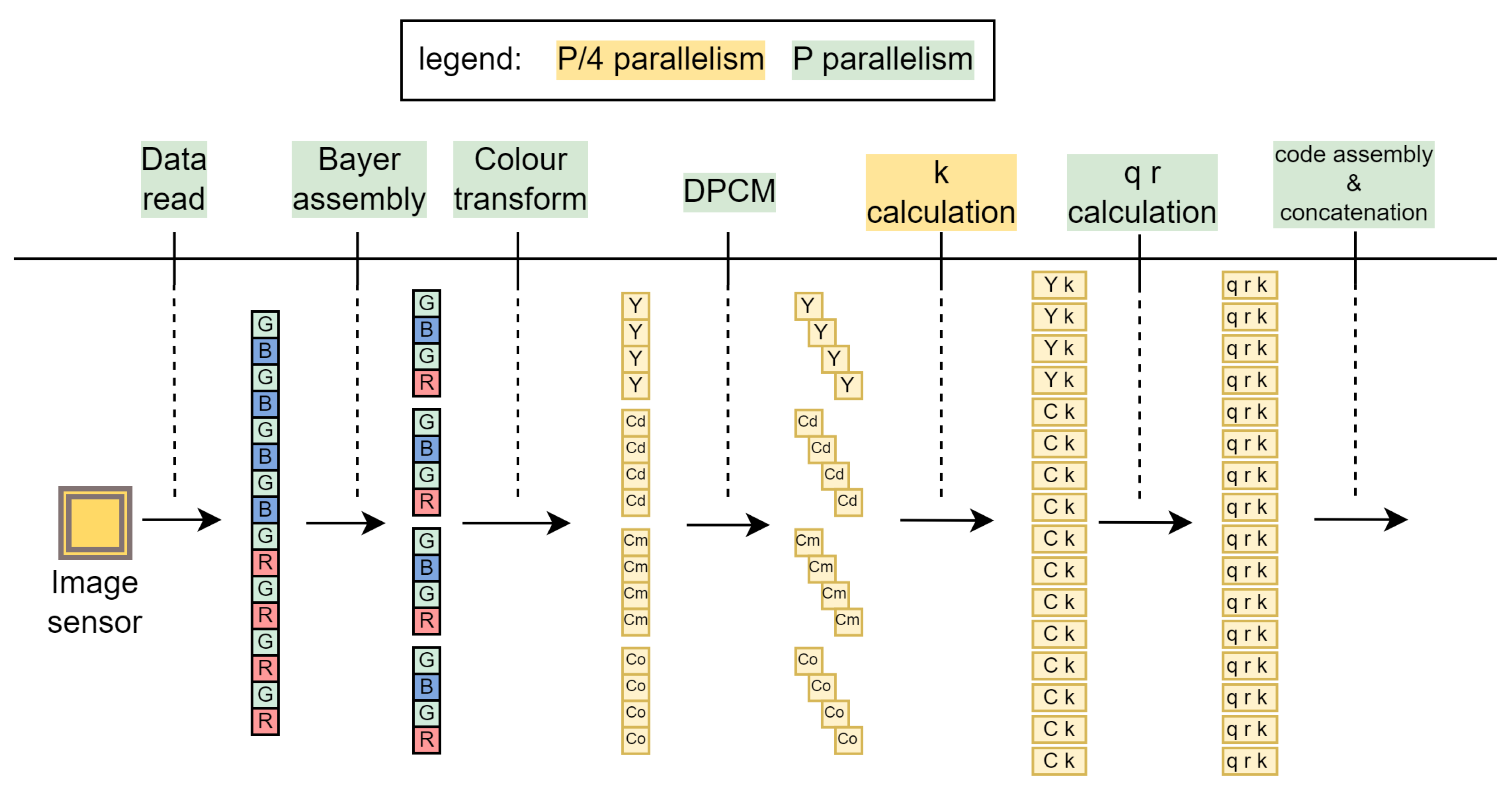
The main contribution of this work in the field of image compression is the efficient parallelization of the algorithm. We use partial parallelism in one phase and full parallelism in all other phases. At the beginning, the pixels
P supplied by the image sensor are read completely independently and in parallel. After the line memories are sufficiently filled,
Bayer elements are formed in parallel and the translation to YCdCmCo is performed. The calculation of the parameter
k is the only partially parallelized step where
modules are used in parallel to calculate inherently sequential variables from the Algorithm 1, as explained in
Section 4.2. All other modules are fully parallel with
P parallel modules.
Figure 8.
Example of parallelism in case of parallel pixels supplied by the image sensor.
Figure 8.
Example of parallelism in case of parallel pixels supplied by the image sensor.
4.2. Dynamically Adjustable Compression Parameter k
As described in Algorithm 1, the variables are updated after each pixel (line 6 of Algorithm 1), and the current value of
depends on the previous value
(line 13). The calculation is sequential by nature, which is not compatible with the fact that the image sensor provides data for multiple pixels in parallel. However, as long as this sequential calculation takes place within one period of the clock, there is no problem. You can mitigate this problem by splitting the algorithm into smaller and shorter calculations, i.e. by implementing a pipeline as we did for the third loop (line 8). We divide the calculation of
k into several stages, as shown in
Figure 9. Since the four channels (Y,Cd,Cm,Co) are independent of each other, the pipeline can be implemented partially in parallel.
4.3. Code Generation
The codes are generated in two steps. In the first step, remainder
r and quotient
q are calculated, while the actual codes are generated in the second step. With the bit slicing operator
[a:b],
a and
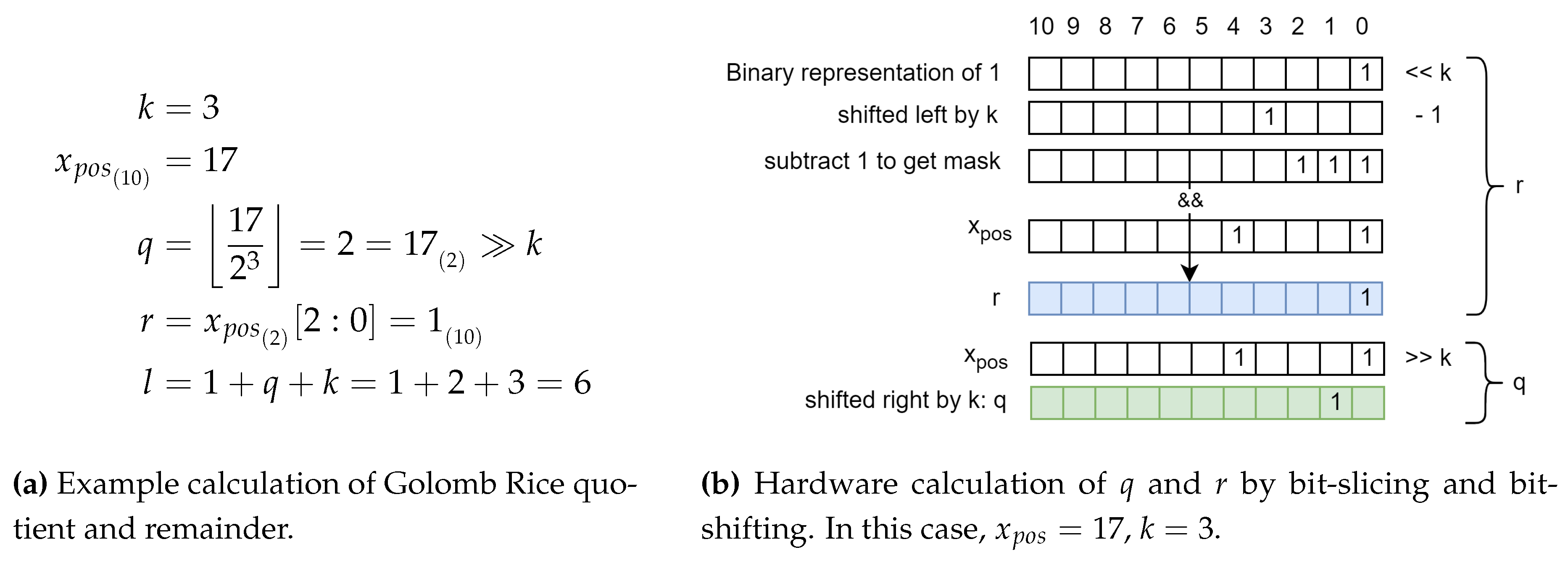
b are dynamic in our algorithm, i.e. they change depending on the image data entered. Since VHDL does not support dynamic ranges, the bit slice operation is implemented as bit masking and bit shifting instead. As shown in
Figure 10, a unary mask of width
k is generated for the binary representation of
r, effectively truncating higher bits. The quotient
q is simply calculated by bit shift, which supports dynamic shift values in VHDL.
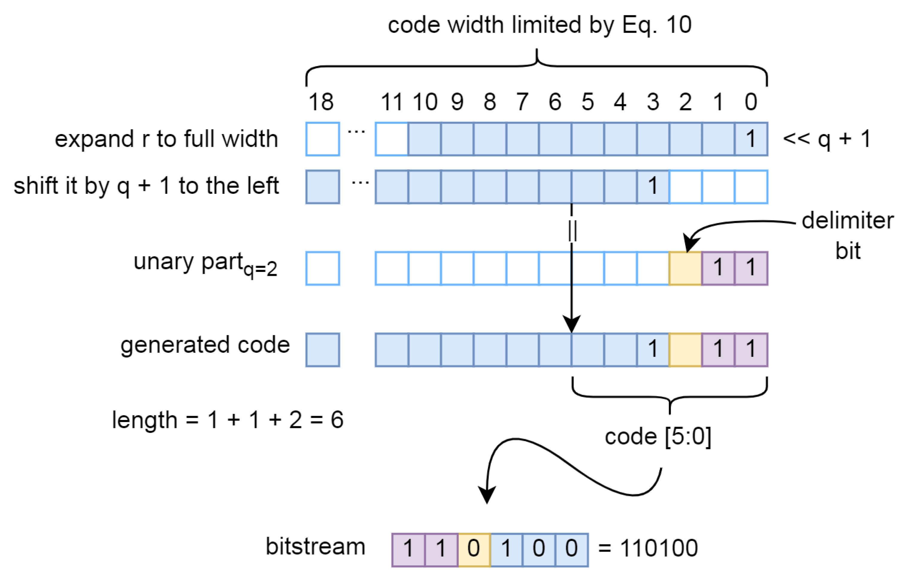
Theoretically, the code is composed by concatenating the unary part, the delimiter bit and the remainder bits. A simple solution would be to use the VHDL concatenation operator
&, but the dynamic nature of the problem requires a slightly more complex solution, as shown in
Figure 11. The final code is generated by concatenating the pre-generated unary part and the
r shifted to the right by
. The addition
is added to create space for a delimiter bit
’0’. At the same time, the code length is calculated to indicate the actual number of valid bits in the fixed-width output that represents the code. The output of the code generation module is therefore a fixed-width vector, with the LSB bits representing the code and the fixed-width vector indicating the number of relevant bits.
4.4. Parallel Code Concatenation
Following the discussion in
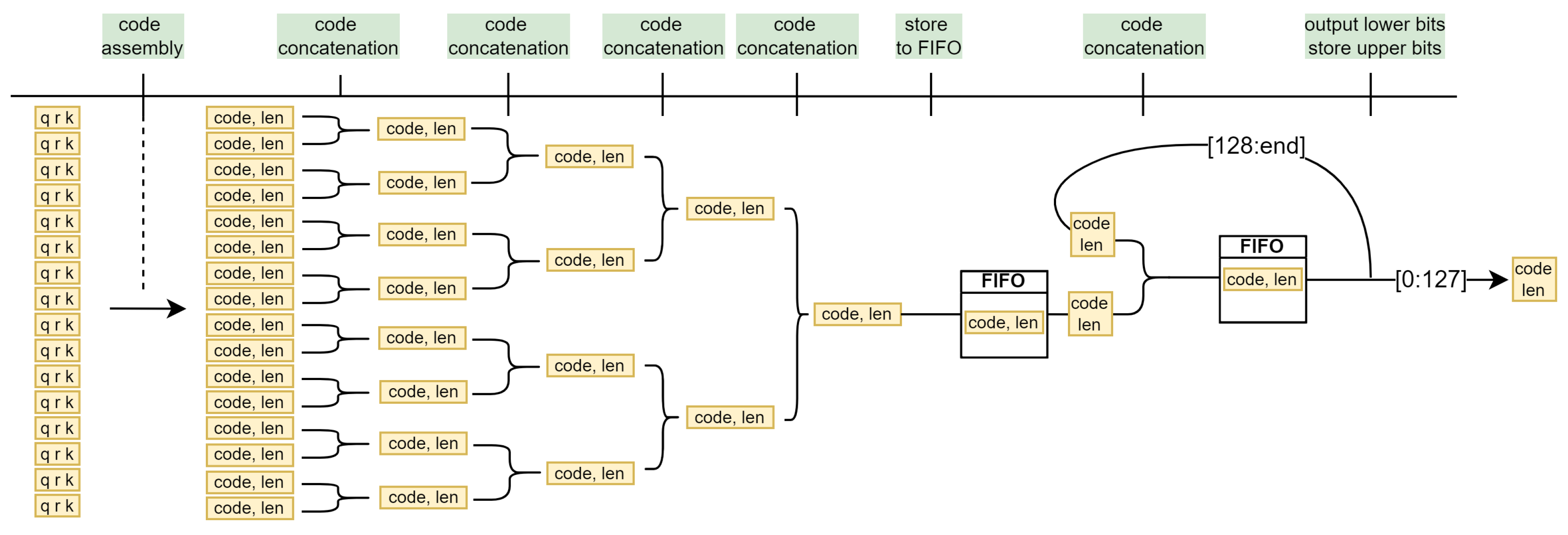
Section 3.7, we propose an extremely simple tree-like solution with a recursive terminal branch. In the first stage, 16 parallel code generator modules construct the codes, which are then concatenated in the subsequent layers. The maximum code length in the last layer can be up to
bits wide, which is still a manageable width for a multiplexer. If more than 128 bits are generated, they are output over the next
cycles, and a FIFO module serves as a buffer for the codes generated during this time. Only the lower 128 bits are output at the output for each clock cycle. The remaining bits form a new code, which is fed back through a recursive branch. The final output is therefore always a 128-bit wide bit stream with an additional 1-bit valid flag, which indicates that the data on the rail is valid and can be retrieved by the external modules.
Figure 12.
Pipelined bitstream generation on 16 parallel pixels.
Figure 12.
Pipelined bitstream generation on 16 parallel pixels.
5. Results
The proposed lossless compression algorithm and its FPGA implementation are presented in terms of compression efficiency, speed and FPGA resource utilisation. Motivated by other work in the field, we evaluate the algorithm with the KODAK dataset [
38], the KID dataset [
42] and our own high-resolution images.
To evaluate compression efficiency, we use the metrics
bits per pixel (BPP) and
compression ratio (CR), which are defined as follows:
To evaluate throughput, we define absolute or
effective throughput (
13). For a fair comparison, we scale the effective throughput with the number of parallel pixels
P ().
5.1. Compression Efficiency
The algorithm works with Bayer CFA pattern images, therefore RGB colour images are first converted into Bayer CFA patterns during evaluation. This is done by subsampling the colour image, whereby only one colour component is retained for a single pixel, resulting in a Bayer CFA pattern. The size of the reference file is then defined as the size of the Bayer CFA image, i.e. the number of pixels multiplied by 8 bits (1 byte).
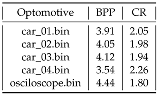
With high-resolution images (18 megapixels) we achieve a CR of 2.26 (
Table 1). This is a sequence of very similar neighbouring pixels, resulting in a large number of difference values close to 0, and requiring only a single bit to encode each pixel.
Table 1.
Lossless compression on 18 Mpixel images [BPP]. Initially 8 BPP.
Table 1.
Lossless compression on 18 Mpixel images [BPP]. Initially 8 BPP.
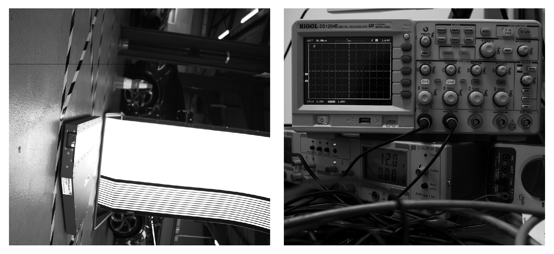
Figure 13.
25 megapixel images. CR ratio 2.26 and 1.80, respectively.
Figure 13.
25 megapixel images. CR ratio 2.26 and 1.80, respectively.
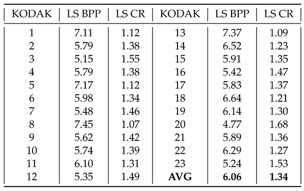
We evaluate our compression using a KODAK image set consisting of 24 768x512 images in
Table 2. The lower CR value (1.34 on average) is due to the lower resolution and high level of detail of the KODAK images, where neighbouring pixels are less similar.
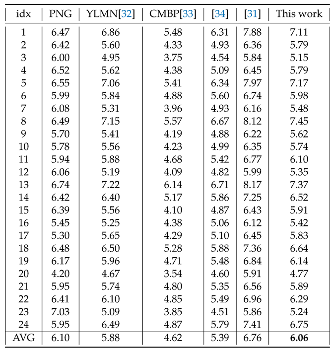
In
Table 3 we compare our algorithm with the PNG standard and the work of [
32,
33,
34]. We achieve comparable results to the PNG standard, but a worse CR when compared to the mentioned works. However, the goal of the proposed algorithm is not a state-of-the-art CR but high throughput with satisfactory CR for high resolution images. This is achieved by using parallelism and low complexity operators.
5.2. Maximum Frequency and Resource Utilisation
The algorithm is implemented on Xilinx Zynq UltraScale+ [
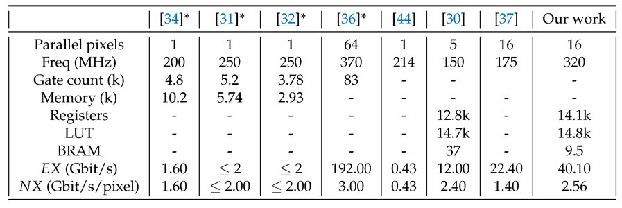
43] FPGA and runs at 320 MHz. It consumes 14.1k LUT, 14.8k registers and 9.5 BRAM blocks which is less than 10% of all available resources. Due to pipelining and parallelism, the effective throughput is continuously 16 pixels per clock cycle , i.e.
. We outperform other FPGA implementations such as [
30,
37,
44] in both effective and normalised throughput. The latter achieves high throughput through a high degree of parallelism like our work. However, our work operates at almost twice the frequency, which increases the effective throughput by the same ratio.
Some of the published works on hardware image compression implement the algorithm on application specific integrated circuits (ASIC). The comparison of FPGA and ASIC implementations is challenging due to different technology performance. However, to show the effectiveness of our design, we compare our work with several ASIC implementations. In the works of [
31,
32] and [
34], the maximum operating frequency achieved was 250 MHz and 200 MHz, respectively. The effective throughput was not reported, but due to the lack of parallelism, it is estimated to be 1 pixel per clock cycle, which is 16 times less than our work.
The only algorithm that outperfoms ours was [
36], where the maximum operating frequency for the ASIC design was 370 MHz and the effective throughput was 192 Gbit/s for parallel processing of 64 pixels. It should be noted that ASICs achieve much higher frequencies than FPGA implementations, but at the cost of high development costs and non-reconfigurability, and that they are usually used in the final stage of a product development after the design has been verified on an FPGA.
Table 4.
Resource and throughput comparison to other works. Publications marked with asterisk * are ASIC based.
Table 4.
Resource and throughput comparison to other works. Publications marked with asterisk * are ASIC based.
6. Discussion
The goal of the research was to close the gap in high-speed image compression on FPGA while fully utilising data parallelism. Several works in this area offered some commendable solutions, but none could match the throughput of modern high-speed high-resolution cameras. We have successfully combined, modified and optimised well-known principles of lossless compression to develop a lightweight, scalable and high-throughput image compression that can easily keep up with current and future cameras while ensuring a competitive compression ratio. Through effective pipelining, operating frequencies of up to 320 MHz with a continuous throughput of 40 Gbit/s are achieved, which significantly outperforms all other existing FPGA implementations for image compression. The compression principles presented in this work can also be applied to other compression tasks such as video, audio or data compression with minimal modifications, and lossy support can be added immediately. Future work will focus more on improving the compression ratio, e.g. by exploring new colour space translations, applying different compression principles and trying out different prediction filters.
Author Contributions
Conceptualization, Ž.R., A.G. and A.T.; methodology, Ž.R.; software, Ž.R.; validation, Ž.R., A.G. and A.T.; formal analysis, Ž.R.; investigation, Ž.R.; resources, A.G.; data curation, Ž.R.; writing—original draft preparation, Ž.R.; writing—review and editing, Ž.R., A.G. and A.T.; visualization, Ž.R.; supervision, A.T.; project administration, A.G. and A.T.; funding acquisition, A.T. All authors have read and agreed to the published version of the manuscript.
Funding
This work was supported by the Slovenian Research Agency (research program grant number P2-0415).
Data Availability Statement
Conflicts of Interest
The authors declare no conflicts of interest.
Abbreviations
The following abbreviations are used in this manuscript:
| AGOR |
Adaptive Golomb-Rice Encoder |
| ASIC |
Application Specific Integrated Circuit |
| BPP |
Bits Per Pixel |
| C++ |
C Plus Plus |
| CCSDS |
Consultative Committee for Space Data Systems |
| CFA |
Colour Filter Array |
| CPU |
Central Processing Unit |
| CR |
Compression Ratio |
| DPCM |
Differential Pulse-Code Modulation |
| FPS |
Frames Per Second |
| FPGA |
Field-Programmable Gate Array |
| GPU |
Graphics Processing Unit |
| IP core |
Intellectual property core |
| LVDS |
Low Voltage Differential Signaling |
| VHDL |
VHSIC Hardware Description Language |
| VHSIC |
Very High Speed Integrated Circuit |
| YCCC |
Y-Cd-Cm-Co Colour Space |
References
- Petrosyan, T.; Mkrtchyan, H. Application Of Motion Capture Systems In Ergonomic Analysis. Armenian Journal of Special Education 2019, 6. [Google Scholar] [CrossRef]
- Eriksson, I.; Gren, P.; Powell, J.; Kaplan, A. New high-speed photography technique for observation of fluid flow in laser welding. Optical Engineering - OPT ENG 2010, 49. [Google Scholar] [CrossRef]
- Neri, P. Frequency-band down-sampled stereo-DIC: Beyond the limitation of single frequency excitation. Mechanical Systems and Signal Processing 2022, 172, 108980. [Google Scholar] [CrossRef]
- Kowalski, Piotr. Measurements of Vibration Using a High-Speed Camera – Comparative Tests. Vibrations in Physical Systems 2020, 31, 2020211–1. [Google Scholar] [CrossRef]
- Optomotive, d.o.o. . Smilodon 10G EVO / 25MP [Online]. Available: https://www.optomotive.com/en/products/smilodon/smilodon-10g-evo-25mp/. [Accesed: 2. 2. 2024].
- Altamimi, A.; Ben Youssef, B. Lossless and Near-Lossless Compression Algorithms for Remotely Sensed Hyperspectral Images. Entropy 2024, 26. [Google Scholar] [CrossRef]
- Makala, R.; Ponnaboyina, R.; Mamidisetti, G. An Efficient Image Compression Using Pixel Filter for Social media applications. International Journal of Innovative Computing and Applications 2021, 13, 1. [Google Scholar] [CrossRef]
- Deigant, Y.; Akshat, V.; Raunak, H.; Pranjal, P.; Avi, J. A proposed method for lossless image compression in nano-satellite systems. In Proceedings of the 2017 IEEE Aerospace Conference; 2017; pp. 1–11. [Google Scholar] [CrossRef]
- Liu, F.; Hernandez-Cabronero, M.; Sanchez, V.; Marcellin, M.W.; Bilgin, A. The Current Role of Image Compression Standards in Medical Imaging. Information 2017, 8. [Google Scholar] [CrossRef]
- Pan, G.; Wang, L. Swallowable Wireless Capsule Endoscopy: Progress and Technical Challenges. Gastroenterology research and practice 2012, 2012, 841691. [Google Scholar] [CrossRef]
- Rao, G.S.; Rani, S.S.; Rao, B.P. Computed Tomography Medical Image Compression using Conjugate Gradient. In Proceedings of the 2019 International Conference on Wireless Communications Signal Processing and Networking (WiSPNET); 2019; pp. 169–173. [Google Scholar] [CrossRef]
- Narayana, P.S.; Khan, A.M. MRI image compression using multiple wavelets at different levels of discrete wavelets transform. Journal of Physics: Conference Series 2020, 1427, 012002. [Google Scholar] [CrossRef]
- .V, A.; Srinivasa, V. Lossless Compression on MRI Images Using SWT. Journal of digital imaging 2014, 27. [Google Scholar] [CrossRef]
- Zou, X. Compression and Decompression of Color MRI Image by Hufmann coding. Master’s thesis, Blekinge Institute of Technology, 2018. [Accessed: 19-4-2024].
- Bayer, B.E. Color imaging array, US3971065A, 1975. [Google Scholar]
- Wallace, G. The JPEG still picture compression standard. IEEE Transactions on Consumer Electronics 1992, 38, xviii. [Google Scholar] [CrossRef]
- Taubman, D.; Marcellin, M. JPEG2000: standard for interactive imaging. Proceedings of the IEEE 2002, 90, 1336–1357. [Google Scholar] [CrossRef]
- Barbhuiya, A.J.I.; Laskar, T.A.; Hemachandran, K. An Approach for Color Image Compression of JPEG and PNG Images Using DCT and DWT. In Proceedings of the 2014 International Conference on Computational Intelligence and Communication Networks; 2014; pp. 129–133. [Google Scholar] [CrossRef]
- Deutsch, L.P. DEFLATE Compressed Data Format Specification version 1. 3. RFC 1951, 1996. [Google Scholar] [CrossRef]
- Huffman, D.A. A Method for the Construction of Minimum-Redundancy Codes. Proceedings of the IRE 1952, 40, 1098–1101. [Google Scholar] [CrossRef]
- Gümüş, S.; Kamisli, F. A learned pixel-by-pixel lossless image compression method with 59K parameters and parallel decoding. Multimedia Tools and Applications. [CrossRef]
- Holub, P.; Šrom, M.; Pulec, M.; Matela, J.; Jirman, M. GPU-accelerated DXT and JPEG compression schemes for low-latency network transmissions of HD, 2K, and 4K video. Future Generation Computer Systems 2013, 29, 1991–2006, Including Special sections: Advanced Cloud Monitoring Systems &The fourth IEEE International Conferenceone-Science2011—e-Science Applications and Tools&Cluster, Grid, and Cloud Computing. [Google Scholar] [CrossRef]
- Holub, P.; Matela, J.; Pulec, M.; Šrom, M. UltraGrid: Low-latency high-quality video transmissions on commodity hardware. 10 2012, pp. 1457–1460. [CrossRef]
- Matela, J.; Holub, P.; Jirman, M.; Årom, M. GPU-specific reformulations of image compression algorithms. Proceedings of SPIE - The International Society for Optical Engineering 2012, 8499, 16. [Google Scholar] [CrossRef]
- NVIDIA, T. NVIDIA GTX 580 [Online]. Available: https://www.techpowerup.com/gpu-specs/geforce-gtx-580.c270. [Accesed: 2. 2. 2024].
- CCSDS The Consultative Committee for Space Data Systems. Lossless Multispectral & Hyperspectral Image Compression 2012.
- Barrios, Y.; Rodríguez, A.; Sánchez, A.; Pérez, A.; López, S.; Otero, A.; de la Torre, E.; Sarmiento, R. Lossy Hyperspectral Image Compression on a Reconfigurable and Fault-Tolerant FPGA-Based Adaptive Computing Platform. Electronics 2020, 9. [Google Scholar] [CrossRef]
- Báscones, D.; González, C.; Mozos, D. Parallel Implementation of the CCSDS 1.2.3 Standard for Hyperspectral Lossless Compression. Remote Sensing 2017, 9. [Google Scholar] [CrossRef]
- Fjeldtvedt, J.; Orlandić, M.; Johansen, T.A. An Efficient Real-Time FPGA Implementation of the CCSDS-123 Compression Standard for Hyperspectral Images. IEEE Journal of Selected Topics in Applied Earth Observations and Remote Sensing 2018, 11, 3841–3852. [Google Scholar] [CrossRef]
- Orlandić, M.; Fjeldtvedt, J.; Johansen, T.A. A Parallel FPGA Implementation of the CCSDS-123 Compression Algorithm. Remote Sensing 2019, 11. [Google Scholar] [CrossRef]
- Rahman, K.M.M. A LOW COMPLEXITY IMAGE COMPRESSION ALGORITHM FOR BAYER COLOR FILTER ARRAY. Master’s thesis, University of Saskatchewan, 2018.
- Mohammed, S.K.; Rahman, K.M.M.; Wahid, K.A. Lossless Compression in Bayer Color Filter Array for Capsule Endoscopy. IEEE Access 2017, 5, 13823–13834. [Google Scholar] [CrossRef]
- Chung, K.H.; Chan, Y.H. A Lossless Compression Scheme for Bayer Color Filter Array Images. IEEE Transactions on Image Processing 2008, 17, 134–144. [Google Scholar] [CrossRef] [PubMed]
- Chen, C.A.; Chen, S.L.; Lioa, C.H.; Abu, P.A. Lossless CFA Image Compression Chip Design for Wireless Capsule Endoscopy. IEEE Access 2019, PP, 1–1. [Google Scholar] [CrossRef]
- Kim, H.S.; Lee, J.; Kim, H.; Kang, S.; Park, W.C. A Lossless Color Image Compression Architecture Using a Parallel Golomb-Rice Hardware CODEC. IEEE Transactions on Circuits and Systems for Video Technology 2011, 21, 1581–1587. [Google Scholar] [CrossRef]
- Lee, J.; Yun, J.; Lee, J.; Hwang, I.; Hong, D.; Kim, Y.; Kim, C.G.; Park, W.C. An Effective Algorithm and Architecture for the High-Throughput Lossless Compression of High-Resolution Images. IEEE Access 2019, 7, 138803–138815. [Google Scholar] [CrossRef]
- Fowers, J.; Kim, J.Y.; Burger, D.; Hauck, S. A Scalable High-Bandwidth Architecture for Lossless Compression on FPGAs. In Proceedings of the 2015 IEEE 23rd Annual International Symposium on Field-Programmable Custom Computing Machines; 2015; pp. 52–59. [Google Scholar] [CrossRef]
- Kodak Lossless True Color Image Suite. https://r0k.us/graphics/kodak/. [Accessed: 29-4-2024].
- Bovik, A.C. Handbook of Image and Video Processing (Communications, Networking and Multimedia); Academic Press, Inc.: USA, 2005. [Google Scholar]
- Weinberger, M.; Seroussi, G.; Sapiro, G. The LOCO-I lossless image compression algorithm: principles and standardization into JPEG-LS. IEEE Transactions on Image Processing 2000, 9, 1309–1324. [Google Scholar] [CrossRef]
- Lee, T.Y. A new frame-recompression algorithm and its hardware design for MPEG-2 video decoders. IEEE Transactions on Circuits and Systems for Video Technology 2003, 13, 529–534. [Google Scholar] [CrossRef]
- A capsule endoscopy database for medical decision support. https://web.archive.org/web/20220812212241/https://mdss.uth.gr/datasets/endoscopy/kid/. [Accessed: 29-4-2024].
- AMD. Zync UltraScale+ [Online]. Available: https://www.xilinx.com/products/silicon-devices/soc/zynq-ultrascale-mpsoc.html/. [Accesed: 2. 2. 2024].
- Hinnerson, M. A Resource Efficient, High Speed FPGA Implementation of Lossless Image Compression for 3D Vision. Master’s thesis, Linköping University, 2019. [Accessed: 19-4-2024].
|
Disclaimer/Publisher’s Note: The statements, opinions and data contained in all publications are solely those of the individual author(s) and contributor(s) and not of MDPI and/or the editor(s). MDPI and/or the editor(s) disclaim responsibility for any injury to people or property resulting from any ideas, methods, instructions or products referred to in the content. |
© 2024 by the authors. Licensee MDPI, Basel, Switzerland. This article is an open access article distributed under the terms and conditions of the Creative Commons Attribution (CC BY) license (http://creativecommons.org/licenses/by/4.0/).
