1. Introduction
Photocathode guns are crucial components in various modern electron linear accelerators, including free-electron lasers (FEL) [
1,
2,
3,
4,
5,
6,
7], energy-recovery linacs [
8,
9,
10], Compton scattering sources [
11,
12,
13,
14], and ultrafast electron diffraction (UED) [
15,
16,
17]. The optimal performance of these applications critically depends on the beam quality of the electron sources. In recent years, driven by emerging demands of frontier research and the development of accelerator facilities with enhanced performance, such as high repetition rate x-ray FELs [
18,
19], continuous-wave (CW) photocathode guns have been rapidly developed to produce electron beams with megahertz (MHz) repetition rates and sub-micron normalized emittance [
20]. However, CW photocathode guns, including DC guns [
21,
22], superconducting radio-frequency (SRF) guns [
23,
24,
25], and very-high-frequency (VHF) normal-conducting radio-frequency (NC RF) guns [
26,
27,
28], typically exhibit lower accelerating gradients and cathode fields compared to S- or L-band NC RF guns [
29,
30] operated at low repetition rates. In these CW guns, the electron beam typically has a long bunch length and a large transverse beam size to mitigate the emittance growth induced by space charge forces. Such a beam is more sensitive to optical aberrations such as spherical aberration, chromatic aberration, and multipole field aberration. Consequently, more attention should be paid to its transport so as to achieve a high beam quality.
This study focuses on the aberrations caused by multipole fields. Previous research has theoretically analyzed the coupled-transverse-dynamics aberration induced by a DC quadrupole field in the solenoid or an RF quadrupole field from the RF coupler, leading to an increase in two-dimensional projected emittance [
31,
32]. Experimental studies on several photocathode guns have confirmed that this aberration can be corrected using a downstream quadrupole corrector with appropriate field strength and rotation angle [
31,
33,
34,
35,
36]. Additionally, theoretical studies and simulations have been carried out to investigate the emittance growth generated by sextupole aberration in a solenoid as well as the corresponding correction method [
37]. A successful experimental demonstration of sextupole correction for low-charge beams has also been achieved using a sextupole corrector on a UED beamline [
38].
Since 2021, the second-generation DC-SRF photocathode gun, known as the DC-SRF-II gun, has been installed, commissioned, and brought into stable operation at Peking University [
39,
40,
41]. This gun serves as a high-brightness electron source capable of generating high repetition rate CW electron beams. During the commissioning, we observed that the beam was not only affected by quadrupole aberration in transport but also highly sensitive to sextupole aberration. Moreover, the transverse beam distribution became more intricate at relatively high bunch charges up to 100 pC. Therefore, we analyzed the effects of multipole fields on electron distribution and transverse emittance. Especially, we developed a method for rapid characterization of multipole field effect, based on which correction of multipole field aberrations was performed without extensive parameter scanning.
This paper presents a detailed description of our study on the characterization and correction of multipole field effect on electron beams. The remaining part of the paper is organized as following.
Section 2 presents an overview of the DC-SRF-II photocathode gun and the beamline. Especially, we analyze the sources of multipole fields in the beamline.
Section 3 discusses the impacts of multipole fields on transverse beam performance, including theoretical analyses ignoring space charge effect and numerical simulations considering space charge effect.
Section 4 details the method for rapid characterization and correction of multipole fields. Both simulation results and experimental studies are included. Finally, we give a summary in
Section 5.
2. Overview of the DC-SRF-II Photocathode Gun and the Beamline
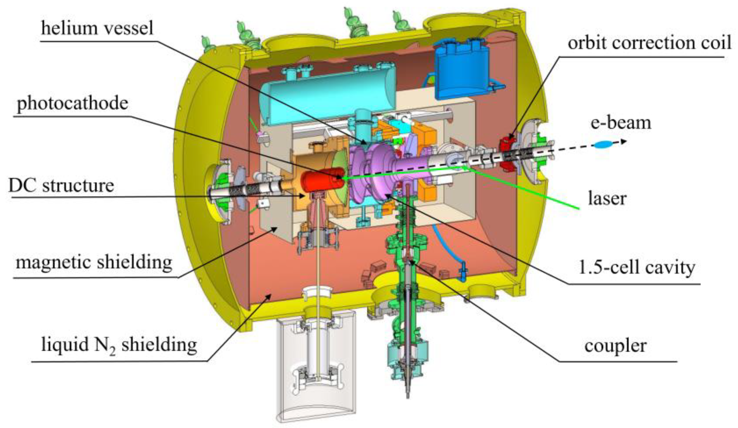
The overall structure of the DC-SRF-II gun is illustrated in
Figure 1. It combines a 100 kV DC gap and a 1.3 GHz 1.5-cell SRF cavity, which are connected by a short drift tube. A K
2CsSb photocathode is located in the DC gap and its surface field is 6 MV/m. For the experimental study presented in this paper, the RF cavity is typically operated at an on-axis peak field between 18 to 23 MV/m, which can boost the electron beam energy to 1.9~2.5 MeV. In the cryomodule of the DC-SRF-II gun, an orbit correction coil is installed at the exit to finely adjust the orbit of the extracted electron beam.
To characterize the beam quality, a dedicated diagnostic beamline has been built downstream of the electron gun, as shown in
Figure 2. The first solenoid (Sol1), located at the gun exit, serves for beam focusing and emittance compensation. Multiple YAG:Ce screens (Y1-Y5) are installed along the beamline to measure the transverse beam distribution. The scanning slits (S1/S2) and screens (Y3/Y4) are used to measure the transverse phase space and projected emittance at different positions using the single-slit scanning method [
42]. Finally, the second solenoid (Sol2) focuses the beam either into a downstream beam dump or through a 90° deflection magnet for energy measurement.
During the commissioning of DC-SRF-II photocathode gun, a distinct distortion of the transverse beam distribution has been observed. After ruling out beam collimation as a cause, this distortion was primarily attributed to the influence of multipole fields. There are two potential sources of multipole fields in our experiments: the asymmetric structure of the RF cavity, which is a result of the single coaxial RF coupler design for the DC-SRF-II gun, and the field distortions in magnetic elements, such as undesired multipole fields in the solenoid generated by the asymmetry of the iron yoke and coil [
31,
32,
33].
To investigate the impact of the first potential source, the three-dimensional electromagnetic field distribution of the SRF cavity was simulated using CST Microwave Studio [
43]. By performing Fourier analysis on the angular magnetic field at the location of the coupler, we determined the relative strength of various multipole fields [
32]. The ratio between the quadrupole/sextupole and monopole strengths at a distance of 10 mm to the cavity axis is 2.9%/1.1%. On the other hand, since the RF coupling port is located at 45 mm downstream of the SRF cavity’s exit iris, the angular magnetic field therein is typically below 2 Gs. Consequently, the multipole field strength caused by the coupler is minimal. This has been validated by our particle tracking simulation, which indicates that the impact of RF coupler's multipole fields on the beam can be neglected.
To analyze the second source of multipole fields, a three-dimensional translational Hall probe was employed to measure the field distribution of the magnets/coils. The results indicate strong multipole fields in both the orbit correction coil in the cryomodule and the solenoids. Within the orbit correction coil, while the quadrupole field component is small, there is a noticeable sextupole field. When the magnetic field at the center of the coil is 10 Gs, the integrated field strength for the normal sextupole component reaches 2.43 Gs/cm. Therefore, we finally gave up using this correction coil. For the two solenoids shown in
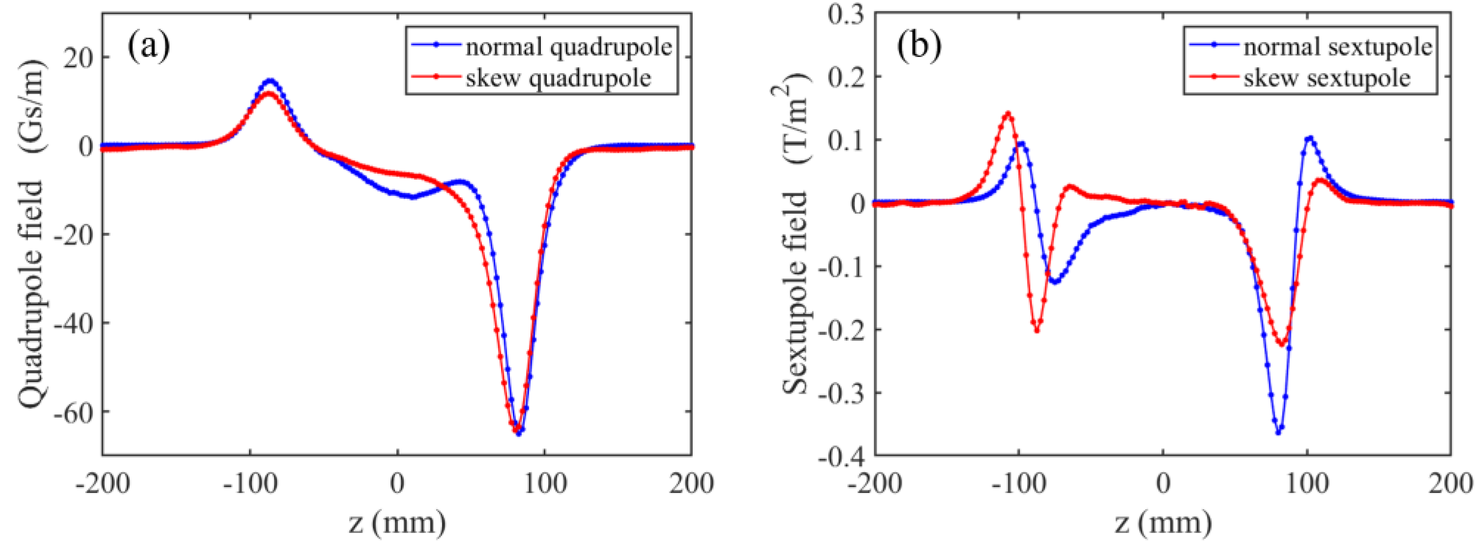
Figure 2, the distributions of multipole fields are quite different, but both of them have distinct quadrupole and sextupole field components at the entrance and exit. Taking Sol1 as an example, when the on-axis peak magnetic field strength reaches 480 Gs, the integrated field strength of the normal quadrupole component at two ends is -2.11 Gs and 0.47 Gs, respectively, while that of the normal sextupole component is -0.63 Gs/cm and -0.22 Gs/cm, respectively, as shown in
Figure 3.
3. Beam Aberration due to Multipole Fields
3.1. Emittance Growth and Beam Profile Evolution due to Multipole Fields
Previous research [
31] has shown that the effects of the RF quadrupole field in a photocathode gun can be mitigated by applying a weak DC quadrupole field. To simplify the analysis, this study primarily focuses on the impact of DC multipole fields on transverse beam dynamics, particularly investigating the emittance growth and beam profile evolution induced by multipole field aberrations. First, we consider normal multipole fields, whose transverse distribution can be expressed as
where
represents the strength of the normal 2(n+1)-pole field.
A multipole field with an arbitrary rotation angle can be regarded as the result of rotating a normal multipole field counterclockwise by an angle
α around the z-axis (the direction of beam propagation). By applying a coordinate transformation to Equation (1), the transverse distribution of the multipole field with a rotation angle
α is given by
The equation of motion for electrons in a multipole field can be expressed as
With thin lens approximation, the change in transverse momentum of the electrons after passing through the multipole field can be calculated as
where
L is the effective length of the multipole field.
To simplify the analysis, we assume a cylindrically uniform electron beam with a radius
R, zero initial emittance, and zero energy spread. For an arbitrary electron, the initial phase space coordinates can be expressed as
with
and
. After traversing the multipole field (neglecting the space charge effect), its coordinates become
The second-order moments of
and
for the electron beam are
The multipole field induced normalized emittance growth in the x direction can then be expressed as
where
represents the initial transverse root mean square (rms) size of the beam. In the y direction, we can get the same expression.
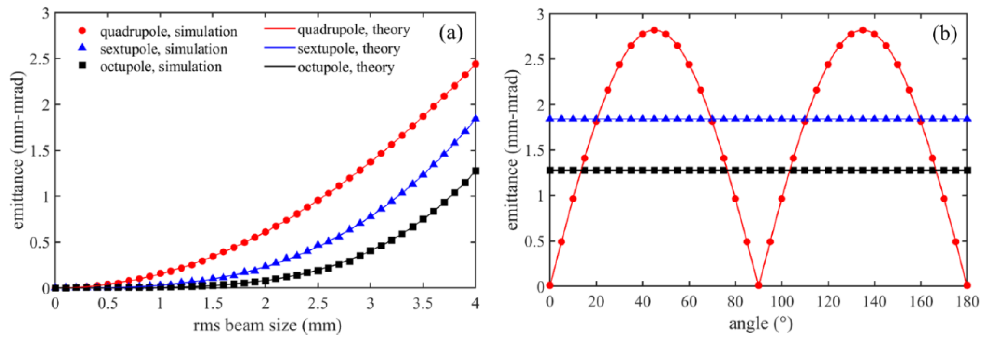
Equation (7) shows that the emittance growth due to a multipole field is closely related to the transverse beam size
and the integrated field strength
LKn. As a crosscheck of the equation, we used GPT code [
44] to simulate the multipole field induced emittance for different transverse beam sizes and multipole field rotation angles. The results are plotted in
Figure 4 (a) and (b), respectively, together with those calculated using Equation (7). Both results agree very well. Note that in this simulation a 2 MeV electron beam with an initial emittance of zero was assumed and the space charge force was disabled.
Based on Equation (5), the transverse beam profile after a multipole field can be derived. Assuming the electron beam drifts a distance
s downstream from the multipole field, the transverse coordinates of the electrons are given by
where
. Given the weak focusing strength of the multipole field, the transform of the outermost electrons’ coordinates (i.e., a contour for the electron distribution) can be used to represent the beam profile evolution. By substituting
r = R into Equation (8), the parametric equation for the beam profile contour is
Figure 5(a-d) show the x-y plane distribution of the electron beam at the initial state and after 3-m drift under the influence of quadrupole, sextupole, and octupole fields, as simulated by GPT. The black solid lines represent the beam profile contours derived from Equation (9), which indicates the evolution of the transverse beam distribution can be accurately depicted. We also plot the corresponding x-x’ phase space in
Figure 5(e-h). Similarly, the evolution can be depicted with the contour whose parametric equation can be derived from Equations (5) and (8). Note that after passing through the multipole field, the electron beam’s phase space area expands, indicating an increase of emittance.
3.2. Simulation with Space-Charge Forces
When the electron gun operates with large bunch charges, space charge forces would significantly intensify the aberrations. For a more accurate analysis, space charge effect should be taken into account in the simulation.
We first investigated the evolution of transverse beam profile along the same beamline as the DC-SRF-II gun using the GPT code. The electron beam has a bunch charge of 100 pC and a kinetic energy of 2 MeV. After being focused by the solenoid, the beam then passed through either a normal quadrupole field with an integrated strength of 3 Gs or a sextupole field with an integrated strength of 5 Gs/cm. The solenoid has a peak axial field of 490 Gs and can focus the beam to a waist at z = 4 m.
To evaluate the influence of space charge forces on the evolution of the transverse beam profile, the GPT simulation with space charge forces was first stopped at z = 2.5 m, i.e., 1.5 m upstream of the waist. Subsequent simulations without and with space charge forces were then started at z = 2.5 m and stopped at z = 5 m, i.e., 1 m downstream of the waist.
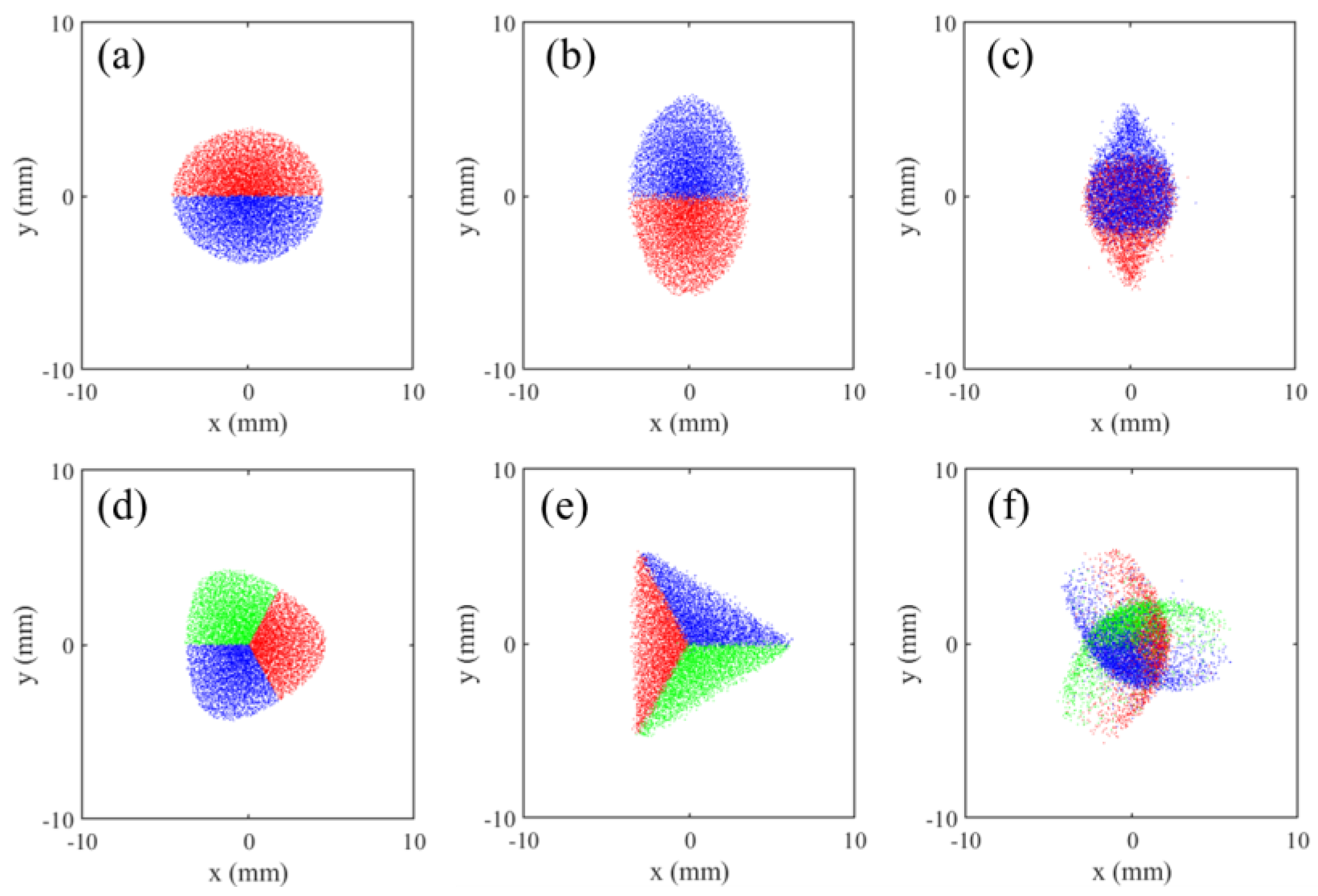
For the quadrupole field case, a scatter plot of the transverse distribution upstream of the waist (at z = 2.5 m) is shown in
Figure 6(a), where red and blue colors are used to tag the particles in the upper and lower regions, respectively.
Figure 6(b)/(c) show the transverse distributions at z = 5 m without/with space charge forces. One can see that the space charge force leads to the formation of water drop shaped profiles and the merging of red and bule particles.
For the sextupole field case, the situation is more complicated.
Figure 6(d) shows the transverse distribution at z = 2.5 m, where the particles in the trisected regions are tagged with red, green, and blue colors. Without space charge forces, triangular profiles are formed at z = 5 m, as shown in
Figure 6(e). However, when space charge forces are included, the red, green, and red particles evolve into moon-shaped profiles separately and get merged at the same time, as shown in
Figure 6(f).
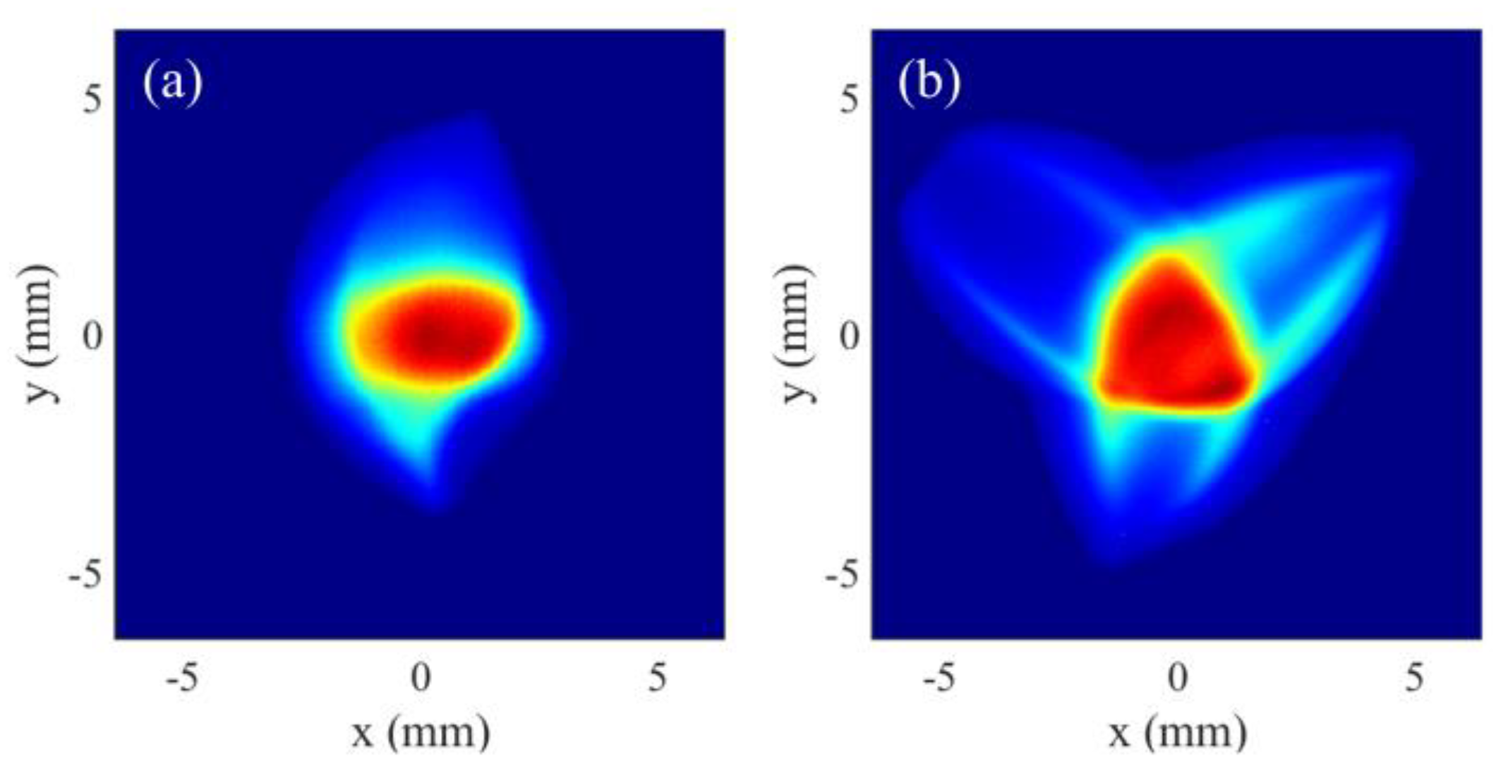
Figure 7 shows the beam aberrations observed in the DC-SRF-II experiments under different operating conditions, which are similar to the simulated transverse distributions in
Figure 6(c) and 6(f).
The presence of multipole fields can also affect the emittance compensation process of the electron beam. For an RF photocathode gun, emittance compensation process [
45,
46] results in the alignment of mismatched slices in phase space, thereby reducing the projected emittance. The presence of multipole fields in the beamline, however, induces asymmetric transverse forces on the beam, which would disrupt the compensation process.
Figure 8 shows the simulated evolution of transverse beam size and emittance when a focused electron beam (after the solenoid) traverses a normal quadrupole or sextupole field. The conditions for the simulation are consistent with those in
Figure 6. For the quadrupole field case, the defocusing/focusing in the x/y direction affects the charge density distribution, which in turn alters the emittance compensation conditions, leading to asymmetric emittance evolution and especially a significant increase in the y direction after the waist. For the sextupole field case, the emittance minimums become much larger. However, both the beam size and emittance remain equal in x and y directions.
Finally, we demonstrated the impact of RF field, for which the RF phase in the GPT simulation was set to +15° off crest acceleration. This leads to a large energy chirp within the electron bunch and the higher/lower energy electrons are at the bunch head/tail. Due to the energy chirp, different electron slices within the bunch experience distinct focusing/defocusing when passing through the solenoid and normal quadrupole field. Near the beam waist, the head slices of the beam get defocused/focused in x/y direction while the tail slices get focused/defocused. This leads to elliptical profiles with the major axes along x/y direction at bunch head/tail, as shown in
Figure 9(b). Consequently, the profile for the whole beam exhibits a cross-star shape, as shown in
Figure 9(a).
4. Multipole Characterization and Correction
4.1. Equivalence of Distributed Multipole Fields
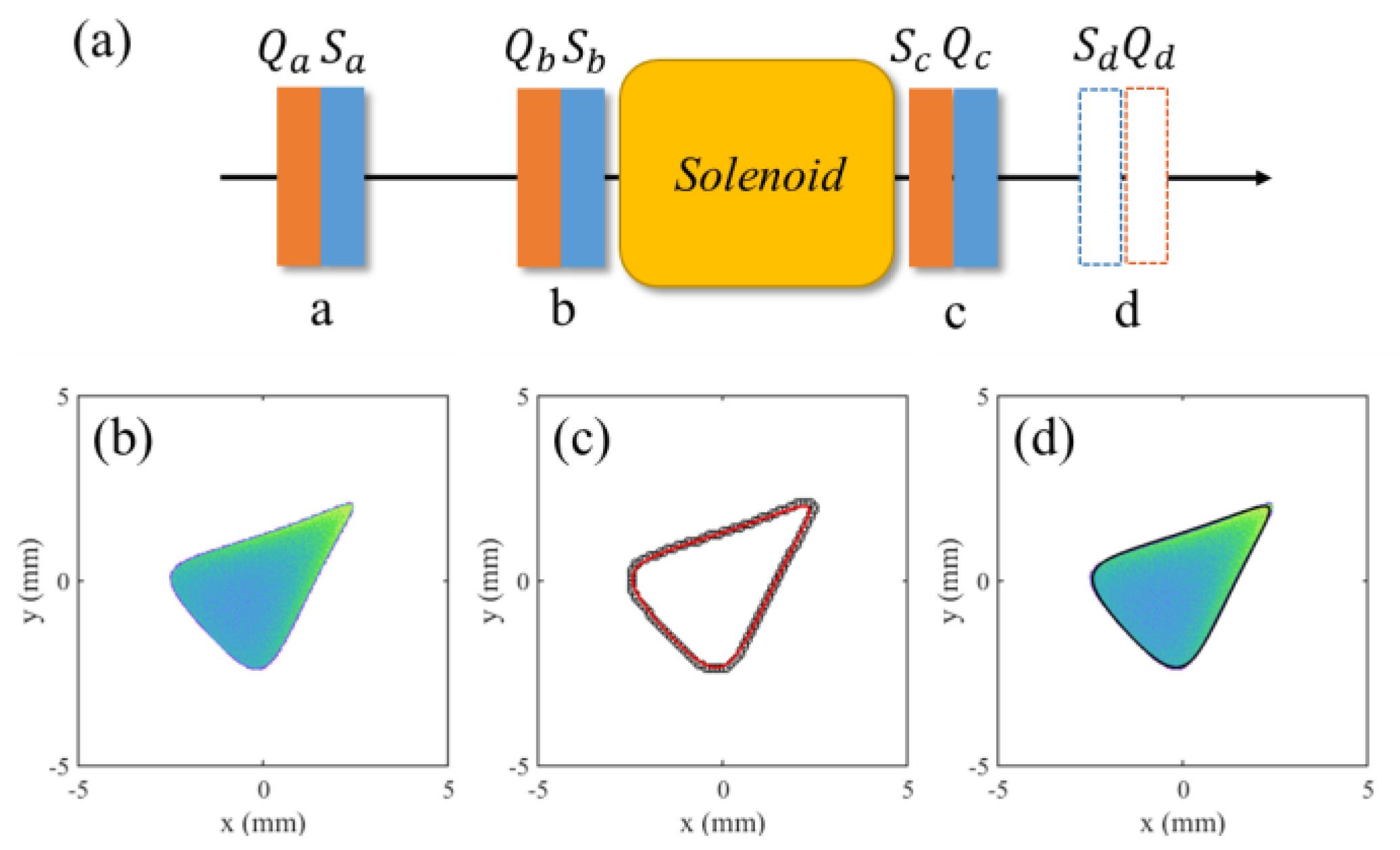
Figure 10(a) illustrates the multipole field error distribution along the diagnostic beamline for the DC-SRF-II gun, in which
Qa,
Qb,
Qc and
Sa,
Sb,
Sc denote the quadrupole and sextupole components of the correction coil in the cryomodule and the entrance and exit ends of the solenoid (Sol1). Considering the relatively weak strength, the multipole fields can be modeled as an equivalent field at position d with combined quadrupole and sextupole components, which are denoted as
Qd and
Sd, respectively. By matching the electron beam profile according to the effect of the equivalent fields, we can inversely derive the strength and rotation angle of each component of the equivalent multipole fields.
To simplify the analysis, we still assume a cylindrically uniform electron beam with zero initial emittance and neglect the space charge effect first. The electron beam has a radius of
Rd at position d and the solenoid, located at a distance
ld from position d, has a focal length of
f. The strength, rotation angle, and effective length of
Qd/
Sd are
K1/
K2,
α1/
α2, and
L1/
L2, respectively. By substituting these parameters into Equation (9) and taking into account the focusing effect of the solenoid, the parametric equation describing the profile contour of the electron beam at a distance
s downstream from position d can be expressed as
where
,
.
We then simulate the evolution of the electron beam’s transverse distribution and emittance growth, for which we assume an electron kinetic energy of 2 MeV, an initial transverse radius of 8 mm, and a solenoid focal length of 2 m.
Figure 10(b) shows the transverse distribution of the electron beam at a distance of 1.5 m downstream from the solenoid, which has passed through positions a, b, and c in
Figure 10(a). The outmost electrons are plotted as black hollow points in
Figure 10(c), which comprises the beam profile contour. A particle swarm algorithm is used afterwards to fit the points to Equation (10). The strength and rotation angle of the equivalent multipole fields,
K1,
α1,
K2 and
α2 at position d are therefore obtained. As a comparison, the fitted contour is plotted in
Figure 10(c) and
Figure 10(d) together with the simulated electron distribution. Both results agree very well.
The emittance growth and caused by the equivalent quadrupole field and sextupole field can be individually calculated using Equation (7). The total equivalent emittance growth is mm-mrad, closely matching the above simulation result of 4.18 mm-mrad with distributed multipole fields. These indicate the beam profile fitting method effectively captures the combined effect of multiple multipole fields on the beam.
As discussed in
Section 3, space charge force would make the situation complicated. To minimize its effect, it is crucial to characterize the multipole fields and make corrections before the beam reaches a waist. On the other hand, to include the contribution from external focusing forces, emittance, and space charge forces into the analysis, the parametric equation in Equation (10) can be modified as
where
R1 represents the transverse beam size at the location of the equivalent multipole fields, while
R2 represents the transverse beam size at the position of measurement/characterization without considering multipole fields.
4.2. Simulation of Multipole Characterization and Correction
Simulations were performed under the operating conditions of the DC-SRF-II gun, with a bunch charge of 100 pC and an electron kinetic energy of 2.3 MeV. We assumed the equivalent quadrupole and sextupole fields were located at z = 1.2 m, while the position for characterization was at z = 3.2 m, i.e., the Y2 screen in
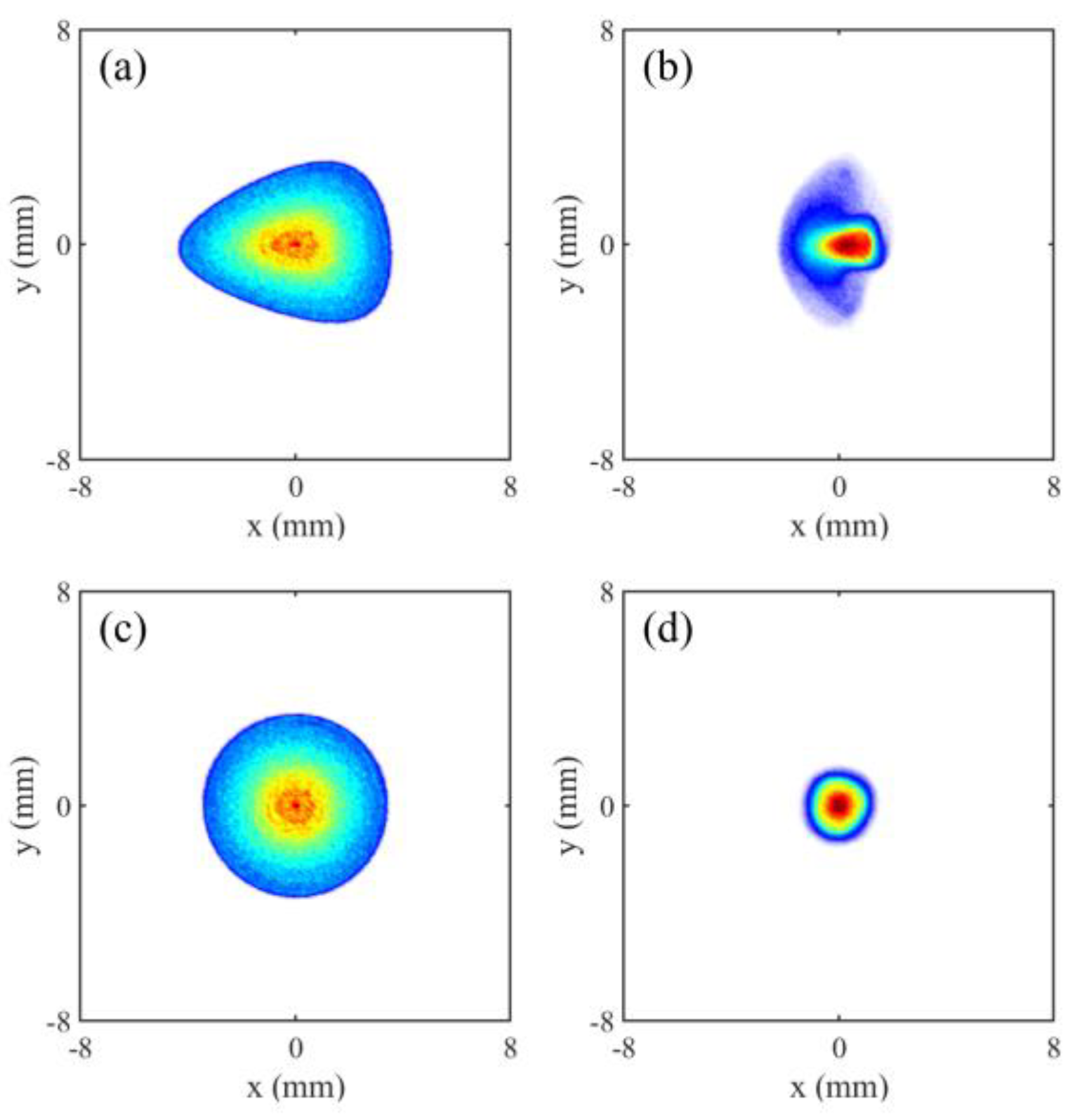
Figure 2. The simulation was first performed without multipole fields. Then the distributed multipole fields along the beamline were included, resulting in the transverse beam profile (at Y2) shown in
Figure 11(a). By fitting the contour of this profile to Equation (11), the integrated field strength of the equivalent quadrupole and sextupole fields were derived to be 2.72 Gs and 2.1 Gs/cm, respectively, while the rotation angles were 179.3° and 64.9°, respectively.
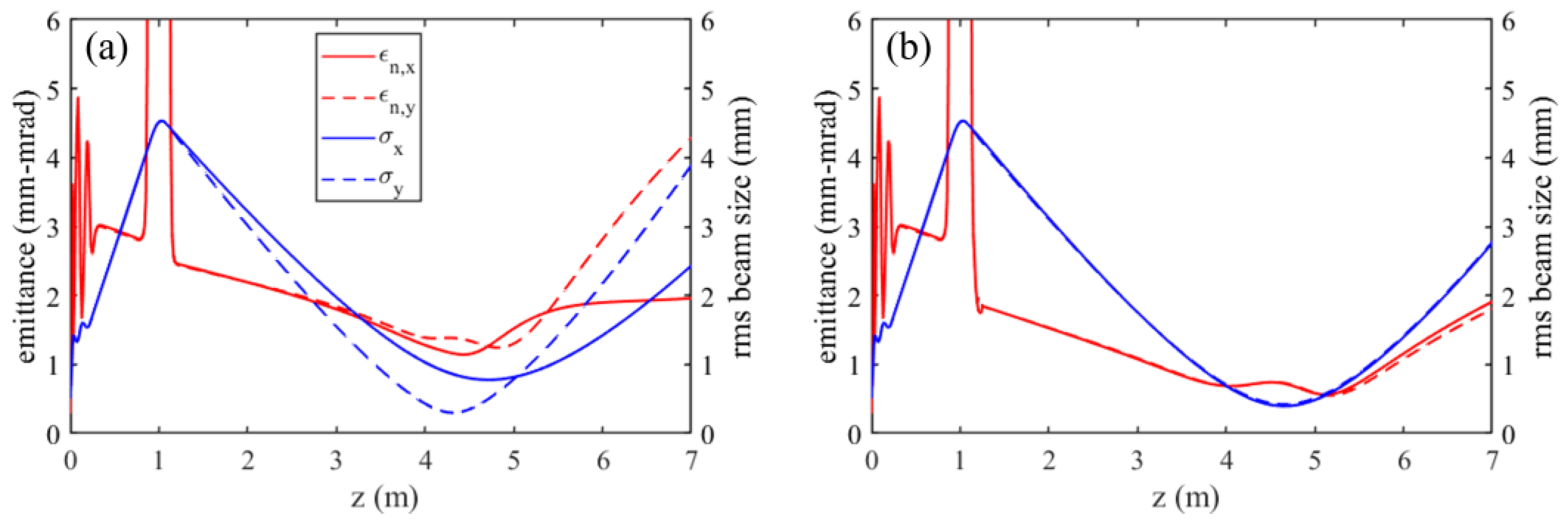
Figure 12(a) displays the evolution of the transverse beam size and emittance along the beamline, both showing evident asymmetry. At z = 5.1 m, where the emittance measurement device (EMD) is located in experiments, the emittance in the x/y direction increases to 1.60/1.39 mm-mrad, while the corresponding transverse beam profile gets significantly distorted, as shown in
Figure 11(b).
Based on the above characterization results, correction quadrupole and sextupole fields were introduced at z = 1.2 m, both having reversed integrated field strengths but same rotation angles as the derived equivalent multipole fields. The simulated transverse beam profiles after correction are shown in
Figure 11(c) and (d), which show significant improvement. In
Figure 12(b), we also present the evolution of the transverse beam size and emittance for the corrected beam. At the EMD position, the emittance in the x/y direction is reduced to 0.56/0.55 mm-mrad.
4.3. Experiments of Multipole Characterization and Correction
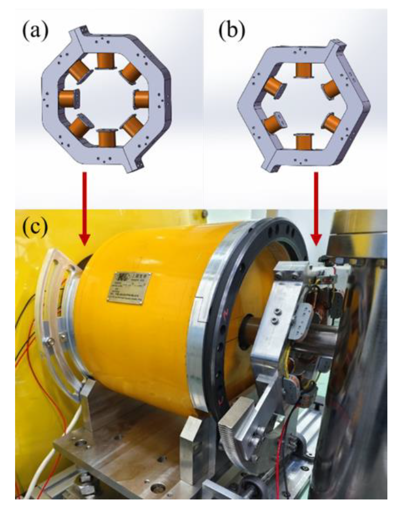
In the diagnostic beamline of the DC-SRF-II gun, two sets of correctors are installed near the Sol1 solenoid, as shown in
Figure 13. The quadrupole corrector before the solenoid has eight coils, constituting a normal/skew quadrupole pair to produce quadrupole field rotatable around the axis. The sextupole corrector after the solenoid has six coils which are mounted on a rotating frame to produce rotatable sextupole field.
Our experiments herein are mainly performed at a bunch charge of 20 pC (the major parameters are listed in
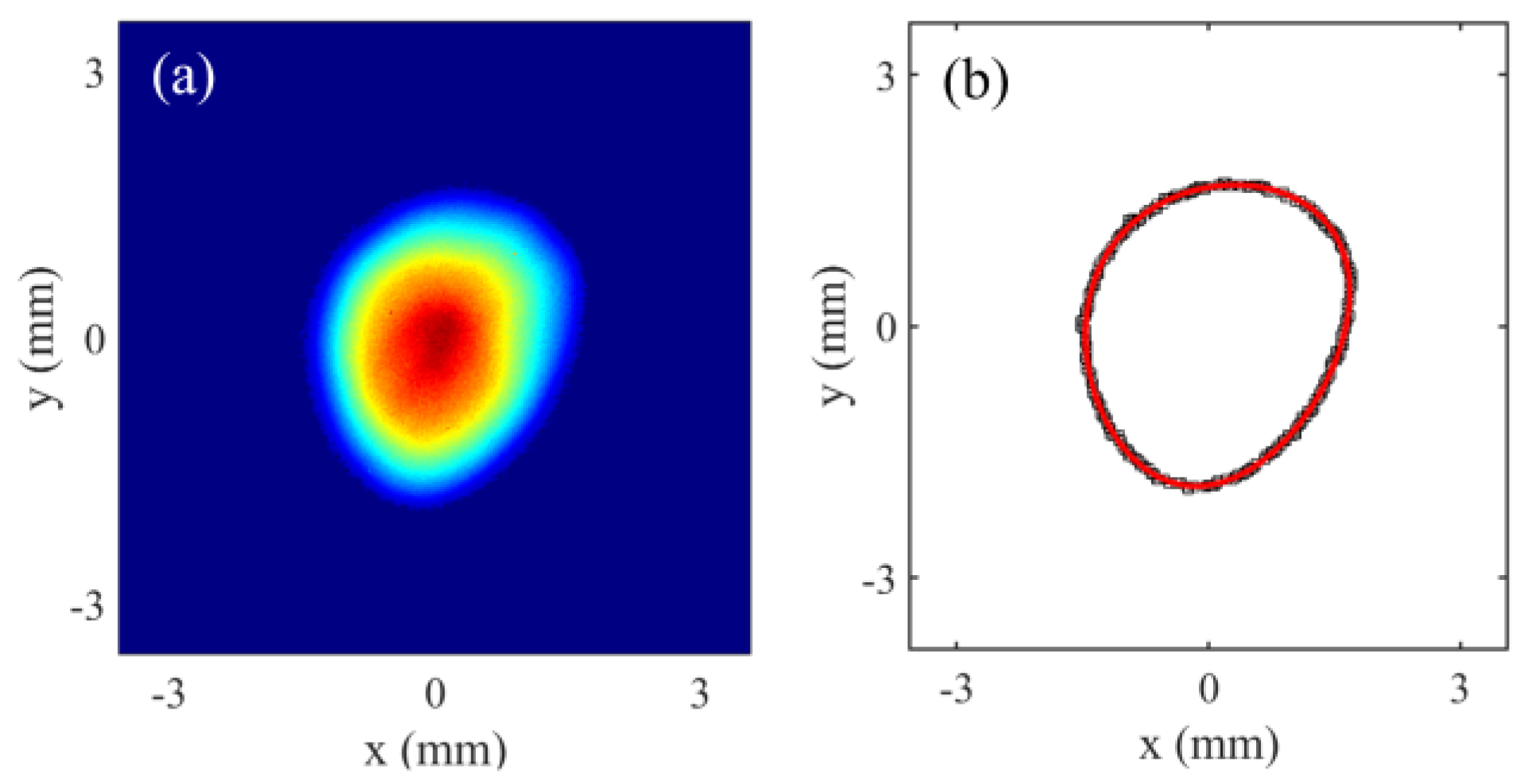
Table 1). In the experiments, we first took the beam profile on the Y2 screen, as shown in
Figure 14(a). Then the contour was extracted from the beam profile, for which a threshold equal to 5% of the maximum intensity was applied. By fitting the extracted contour, plotted as black points in
Figure 14(b), to Equation (11), the rotation angle of the equivalent quadrupole/sextupole field was determined as 114°/34°, while the integrated field strength was 1.68 Gs/1.4 Gs/cm. The fitting curve is depicted by the solid red line in
Figure 14(b).
We finally set the quadrupole and sextupole correctors according to the characterization results.
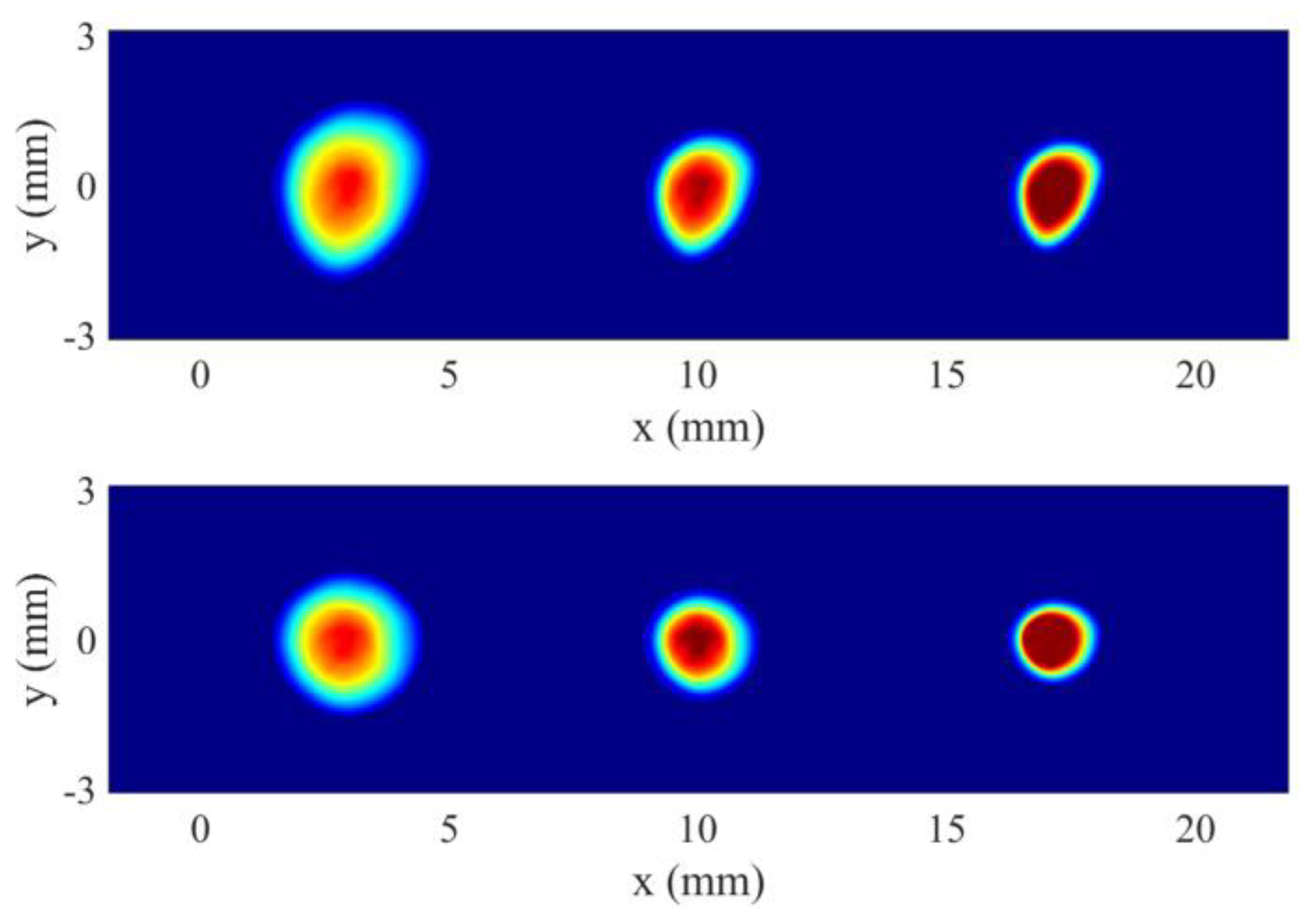
Figure 15 shows the transverse beam profiles on the Y2 screen at different solenoid strength both before and after the corrections. We can see more regular and symmetric electron distributions when the corrections are applied.
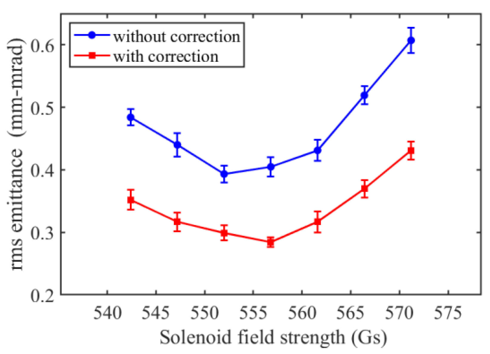
The electron beam emittance was also measured before and after corrections.
Figure 16 shows the results as a function of solenoid field strength. For each measurement after corrections, the strengths and rotation angles of the multipole field correctors were recalculated and adjusted accordingly. From the figure, we can see the optimized/minimum normalized emittance achieved by scanning the solenoid strength was reduced from 0.40 mm-mrad to 0.28 mm-mrad.
Experimental study has also been carried out at a bunch charge of 100 pC, as reported in [
41], which demonstrated a reduction of normalized emittance from 0.73 mm-mrad to 0.54 mm-mrad after multipole field corrections.
5. Conclusions
We have investigated the impact of multipole fields on the transverse performance of electron beam from a CW photocathode gun and revealed the sensitivity of the beam profile and emittance to multipole field errors. We have also developed a method for rapid characterization and correction of multipole field effects, which improve the beam quality significantly while avoiding measuring the distributed multipole field errors in magnets and extensive parameter scanning during correction. This study is expected to benefit the development of high-brightness electron sources.
Author Contributions
Conceptualization, H.J. and S.H.; methodology, H.J., C.T., S.H. and J.Li; software, H.J.; formal analysis, H.J., T.L. and S.H.; investigation, H.J., T.L., J.Liu, Z.L., X.Z., J.Li, K.L., C.T., H.X. and S.H.; resources, S.H., K.L. and J.Li; data curation, H.J., X.Z. and J.Liu; writing—original draft preparation, H.J.; writing—review and editing, H.J., Z.L., H.X., C.T., and S.H.; visualization, H.J.; supervision, S.H. and K.L.; project administration, S.H.; funding acquisition, S.H. and K.L. All authors have read and agreed to the published version of the manuscript.
Funding
This research was funded by the National Key Research and Development Program of China (Grant No. 2016YFA0401904 and 2017YFA0701001) and the State Key Laboratory of Nuclear Physics and Technology, Peking University (Grant No. NPT2022ZZ01).
Institutional Review Board Statement
Not applicable.
Informed Consent Statement
Not applicable.
Data Availability Statement
The data presented in this study will be made available by the authors on request.
Acknowledgments
The authors want to show their gratitude to T. Y. Wang, Y. L. Zhao, J. K. Hao, L. Lin, F. Wang, L. W. Feng and H. M. Xie for very helpful discussions.
Conflicts of Interest
The authors declare no conflicts of interest.
References
- Ackermann, W.; Asova, G.; Ayvazyan, V.; et al. Operation of a free-electron laser from the extreme ultraviolet to the water window. Nature Photonics 2007, 1, 336–342. [Google Scholar] [CrossRef]
- Emma, P.; Akre, R.; Arthur, J.; et al. First lasing and operation of an ångstrom-wavelength free-electron laser. Nature Photonics 2010, 4, 641–647. [Google Scholar] [CrossRef]
- Ishikawa, T.; Aoyagi, H.; Asaka, T.; et al. A compact X-ray free-electron laser emitting in the sub-ångström region. Nature Photonics 2012, 6, 540–544. [Google Scholar] [CrossRef]
- Kang, H.-S.; Min, C.-K.; Heo, H.; et al. Hard X-ray free-electron laser with femtosecond-scale timing jitter. Nature Photonics 2017, 11, 708–713. [Google Scholar] [CrossRef]
- Decking, W.; Abeghyan, S.; Abramian, P.; et al. A MHz-repetition-rate hard X-ray free-electron laser driven by a superconducting linear accelerator. Nature Photonics 2020, 14, 391–397. [Google Scholar] [CrossRef]
- Zhao, Z.; Wang, D.; Gu, Q.; et al. SXFEL: A Soft X-ray Free Electron Laser in China. Synchrotron Radiation News 2017, 30, 29–33. [Google Scholar] [CrossRef]
- Pellegrini, C. The development of XFELs. Nature Reviews Physics 2020, 2, 330–331. [Google Scholar] [CrossRef]
- Neil, G. R.; Bohn, C. L.; Benson, S. V.; et al. Sustained Kilowatt Lasing in a Free-Electron Laser with Same-Cell Energy Recovery. Physical Review Letters 2000, 84, 662–665. [Google Scholar] [CrossRef]
- Neil, G. R.; Behre, C.; Benson, S. V.; et al. The JLab high power ERL light source. Nuclear Instruments and Methods in Physics Research Section A: Accelerators, Spectrometers, Detectors and Associated Equipment 2006, 557, 9–15.
- Gulliford, C.; Bartnik, A.; Bazarov, I.; et al. Demonstration of low emittance in the Cornell energy recovery linac injector prototype. Physical Review Special Topics - Accelerators and Beams 2013, 16, 073401. [Google Scholar] [CrossRef]
- Hartemann, F. V.; Brown, W. J.; Gibson, D. J.; Anderson, S. G.; Tremaine, A. M.; Springer, P. T.; Wootton, A. J.; Hartouni, E. P.; Barty, C. P. J. High-energy scaling of Compton scattering light sources. Physical Review Special Topics - Accelerators and Beams 2005, 8, 100702. [Google Scholar] [CrossRef]
- Gibson, D. J.; Albert, F.; Anderson, S. G.; et al. Design and operation of a tunable MeV-level Compton-scattering-based γ-ray source. Physical Review Special Topics - Accelerators and Beams 2010, 13, 070703. [Google Scholar] [CrossRef]
- Ovodenko, A.; Agustsson, R.; Babzien, M.; et al. High duty cycle inverse Compton scattering X-ray source. Applied Physics Letters 2016, 109, 253504. [Google Scholar] [CrossRef]
- Deitrick, K. E.; Krafft, G. A.; Terzić, B.; Delayen, J. R. High-brilliance, high-flux compact inverse Compton light source. Physical Review Accelerators and Beams 2018, 21, 080703. [Google Scholar] [CrossRef]
- Li, R.; Tang, C.; Du, Y.; Huang, W.; Du, Q.; Shi, J.; Yan, L.; Wang, X. Experimental demonstration of high quality MeV ultrafast electron diffraction. Review of Scientific Instruments 2009, 80, 083303. [Google Scholar] [CrossRef]
- Weathersby, S. P.; Brown, G.; Centurion, M.; et al. Mega-electron-volt ultrafast electron diffraction at SLAC National Accelerator Laboratory. Review of Scientific Instruments 2015, 86, 073702. [Google Scholar] [CrossRef] [PubMed]
- Wu, J.; Tang, M.; Zhao, L.; et al. Ultrafast atomic view of laser-induced melting and breathing motion of metallic liquid clusters with MeV ultrafast electron diffraction. Proceedings of the National Academy of Sciences 2022, 119, e2111949119. [Google Scholar] [CrossRef]
- Galayda, J. N. The Linac Coherent Light Source-II Project. In Proceedings of the 5th International Particle Accelerator Conference, IPAC'14, Dresden, Germany, 15-20 June 2014.
- Zhao, Z. T.; Wang, D.; Yang, Z. H.; Yin, L. SCLF: An 8-GeV CW SCRF Linac-Based X-Ray FEL Facility in Shanghai. In Proceedings of the 38th International Free Electron Laser Conference, FEL'17,, Santa Fe, NM, USA, 20-25 August 2017.
- Sannibale, F. Overview of Electron Source Development for High Repetition Rate FEL Facilities. In Proceedings of the North American Particle Accelerator Conference, NAPAC’16, Chicago, IL, USA, 9-14 October 2016. [Google Scholar]
- Gulliford, C.; Bartnik, A.; Bazarov, I.; Dunham, B.; Cultrera, L. Demonstration of cathode emittance dominated high bunch charge beams in a DC gun-based photoinjector. Applied Physics Letters 2015, 106, 094101. [Google Scholar] [CrossRef]
- Nishimori, N.; Nagai, R.; Hajima, R.; Yamamoto, M.; Honda, Y.; Miyajima, T.; Uchiyama, T. Operational experience of a 500 kV photoemission gun. Physical Review Accelerators and Beams 2019, 22, 053402. [Google Scholar] [CrossRef]
- Janssen, D.; Büttig, H.; Evtushenko, P.; et al. First operation of a superconducting RF-gun. Nuclear Instruments and Methods in Physics Research Section A: Accelerators, Spectrometers, Detectors and Associated Equipment 2003, 507, 314–317.
- Teichert, J.; Arnold, A.; Ciovati, G.; et al. Successful user operation of a superconducting radio-frequency photoelectron gun with Mg cathodes. Physical Review Accelerators and Beams 2021, 24, 033401. [Google Scholar] [CrossRef]
- Petrushina, I.; Litvinenko, V. N.; Jing, Y.; et al. High-Brightness Continuous-Wave Electron Beams from Superconducting Radio-Frequency Photoemission Gun. Physical Review Letters 2020, 124, 244801. [Google Scholar] [CrossRef]
- Sannibale, F.; Filippetto, D.; Papadopoulos, C. F.; et al. Advanced photoinjector experiment photogun commissioning results. Physical Review Special Topics - Accelerators and Beams 2012, 15, 103501. [Google Scholar] [CrossRef]
- Wells, R. P.; Ghiorso, W.; Staples, J.; Huang, T. M.; Sannibale, F.; Kramasz, T. D. Mechanical design and fabrication of the VHF-gun, the Berkeley normal-conducting continuous-wave high-brightness electron source. Review of Scientific Instruments 2016, 87, 023302. [Google Scholar] [CrossRef]
- Sannibale, F.; Filippetto, D.; Qian, H.; Mitchell, C.; Zhou, F.; Vecchione, T.; Li, R. K.; Gierman, S.; Schmerge, J. High-brightness beam tests of the very high frequency gun at the Advanced Photo-injector EXperiment test facility at the Lawrence Berkeley National Laboratory. Review of Scientific Instruments 2019, 90, 033304. [Google Scholar] [CrossRef]
- Akre, R.; Dowell, D.; Emma, P.; et al. Commissioning the Linac Coherent Light Source injector. Physical Review Special Topics - Accelerators and Beams 2008, 11, 030703. [Google Scholar] [CrossRef]
- Krasilnikov, M.; Stephan, F.; Asova, G.; et al. Experimentally minimized beam emittance from anL-band photoinjector. Physical Review Special Topics - Accelerators and Beams 2012, 15, 100701. [Google Scholar] [CrossRef]
- Dowell, D. H.; Zhou, F.; Schmerge, J. Exact cancellation of emittance growth due to coupled transverse dynamics in solenoids and rf couplers. Physical Review Accelerators and Beams 2018, 21, 010101. [Google Scholar] [CrossRef]
- Zheng, L.; Shao, J.; Du, Y.; et al. Overestimation of thermal emittance in solenoid scans due to coupled transverse motion. Physical Review Accelerators and Beams 2018, 21, 122803. [Google Scholar] [CrossRef]
- Zheng, L.; Shao, J.; Du, Y.; et al. Experimental demonstration of the correction of coupled-transverse-dynamics aberration in an rf photoinjector. Physical Review Accelerators and Beams 2019, 22, 072805. [Google Scholar] [CrossRef]
- Bartnik, A.; Gulliford, C.; Bazarov, I.; Cultera, L.; Dunham, B. Operational experience with nanocoulomb bunch charges in the Cornell photoinjector. Physical Review Special Topics - Accelerators and Beams 2015, 18, 083401. [Google Scholar] [CrossRef]
- Schietinger, T.; Pedrozzi, M.; Aiba, M.; et al. Commissioning experience and beam physics measurements at the SwissFEL Injector Test Facility. Physical Review Accelerators and Beams 2016, 19, 100702. [Google Scholar] [CrossRef]
- Krasilnikov, M.; Isaev, I.; Amatuni, G.; et al. Electron Beam Asymmetry Compensation with Gun Quadrupoles at PITZ. In Proceedings of the 38th International Free Electron Laser Conference, FEL’17, Santa Fe, NM, USA, 20-25 August 2017. [Google Scholar]
- Dowell, D. H. Correcting emittance growth due to stray sextupole fields. arXiv:1810.00086, arXiv:1810.00086.
- Gordon, M.; Li, W. H.; Andorf, M. B.; et al. Four-dimensional emittance measurements of ultrafast electron diffraction optics corrected up to sextupole order. Physical Review Accelerators and Beams 2022, 25, 084001. [Google Scholar] [CrossRef]
- Liu, Y. Q.; Chen, M.; Huang, S.; Lin, L.; Liu, K. X.; Quan, S. W.; Wang, F.; Zhao, S. Engineering Design of Low-Emittance DC-SRF Photocathode Injector. In Proceedings of the 39th International Free Electron Laser Conference, FEL'19,, Hamburg, Germany, 26-30 August 2019.
- Zhao, S.; Huang, S.; Lin, L.; Liu, Y.; Jia, H.; Qin, W.; Quan, S.; Liu, K. Longitudinal phase space improvement of a continuous-wave photoinjector toward X-ray free-electron laser application. Nuclear Instruments and Methods in Physics Research Section A: Accelerators, Spectrometers, Detectors and Associated Equipment 2021, 1018, 165796. [Google Scholar] [CrossRef]
- Jia, H.; Li, T.; Wang, T.; et al. High Performance Operation of a Direct-Current and Superconducting Radio-Frequency Combined Photocathode Gun. arXiv:2406.00659, arXiv:2406.00659.
- Tan, T.; Jia, H.; Zhao, S.; et al. Sub-micron normalized emittance measurement for a MeV continuous-wave electron gun. Nuclear Instruments and Methods in Physics Research Section A: Accelerators, Spectrometers, Detectors and Associated Equipment 2023, 1045, 167552.
- CST Studio suite computer simulation technology, http://www.cst.com/.
- General Particle Tracer, http://www.pulsar.nl/gpt/.
- Carlsten, B. E. New photoelectric injector design for the Los Alamos National Laboratory XUV FEL accelerator. Nuclear Instruments and Methods in Physics Research Section A: Accelerators, Spectrometers, Detectors and Associated Equipment 1989, 285, 313–319.
- Serafini, L.; Rosenzweig, J. B. Envelope analysis of intense relativistic quasilaminar beams in rf photoinjectors: A theory of emittance compensation. Physical Review E 1997, 55, 7565–7590. [Google Scholar] [CrossRef]
Figure 1.
A three-dimensional diagram of the DC-SRF-II photocathode gun.
Figure 1.
A three-dimensional diagram of the DC-SRF-II photocathode gun.
Figure 2.
A sketch of the diagnostic beamline for the DC-SRF-II gun. The beamline mainly comprises the photocathode gun (Gun), solenoids (Sol1 and Sol2), YAG:Ce screens (Y1-Y5), scanning slits (S1-S3), 90° deflection magnet, and beam dump.
Figure 2.
A sketch of the diagnostic beamline for the DC-SRF-II gun. The beamline mainly comprises the photocathode gun (Gun), solenoids (Sol1 and Sol2), YAG:Ce screens (Y1-Y5), scanning slits (S1-S3), 90° deflection magnet, and beam dump.
Figure 3.
The measurement results of multipole field components in Sol1. (a) Quadrupole field. (b) Sextupole field.
Figure 3.
The measurement results of multipole field components in Sol1. (a) Quadrupole field. (b) Sextupole field.
Figure 4.
(a) Emittance growth due to the multipole field as a function of beam size. The quadrupole field was rotated by 30°. (b) Emittance growth as a function of the rotation angle of the multipole fields. The initial transverse rms beam size was fixed at 4 mm. The simulation was performed with the GPT code (space charge force turned off), while the theoretical curves were calculated using Equation (7). The integrated quadrupole, sextupole, and octupole field strengths are assumed to be 3 Gs, 3 Gs/cm, and 3 Gs/cm2, respectively.
Figure 5.
Effects of multipole fields on the transverse profile and phase space of a 2 MeV zero- emittance electron beam. (a, e) show the transverse profile and phase space of before the multipole fields. (b, f), (c, g), (d, h) show the transverse profile and phase space 3 m downstream from a rotated quadrupole field, a normal sextupole field, and a normal octupole field, respectively. The multipole field parameters are the same as in
Figure 4(a). The solid black lines in the upper plots were calculated using Equation (9) and the dashed black lines in the lower plots were calculated using Equations (5) and (8).
Figure 6.
The simulated transverse beam profiles after quadrupole field (upper) and sextupole field (lower). (a, d) show the initial profiles (upstream of the waist, at z = 2.5 m), where different colors are used to tag the particles in the bisected/trisected regions. (b, e) and (c, f) show the profiles after a drift of 2.5 m without and with space charge force, respectively.
Figure 7.
eam aberrations observed in the DC-SRF-II experiments under various operating conditions.
Figure 7.
eam aberrations observed in the DC-SRF-II experiments under various operating conditions.
Figure 8.
The simulated transverse beam size and emittance evolution along the beamline with a normal quadrupole field (a) and a normal sextupole field (b) introduced after the solenoid.
Figure 8.
The simulated transverse beam size and emittance evolution along the beamline with a normal quadrupole field (a) and a normal sextupole field (b) introduced after the solenoid.
Figure 9.
The simulated transverse profile of an energy-chirped electron beam after traversing a solenoid and a normal quadrupole field. (a) presents the whole beam at the waist; (b) presents different slices at the waist, where the electron bunch head/tail is on the left/right.
Figure 9.
The simulated transverse profile of an energy-chirped electron beam after traversing a solenoid and a normal quadrupole field. (a) presents the whole beam at the waist; (b) presents different slices at the waist, where the electron bunch head/tail is on the left/right.
Figure 10.
(a) A schematic diagram of multipole field distribution along the DC-SRF-II beamline. (b) The simulated transverse beam profile at a distance of 1.5 m downstream from the solenoid, which has traversed the multipole fields distributed at positions a, b and c. (c) The beam profile contour (black hollow point) and the fitting curve according to Equation (10) (red line). (d) The fitted contour (black line) together with the simulated electron distribution.
Figure 11.
The simulated transverse beam profiles in the presence of multipole fields along the beamline (upper) and after correction (lower). (a, c) and (b, d) are the profiles at Y2 (z = 3.2 m) and the emittance measurement device position (z = 5.1m), respectively.
Figure 11.
The simulated transverse beam profiles in the presence of multipole fields along the beamline (upper) and after correction (lower). (a, c) and (b, d) are the profiles at Y2 (z = 3.2 m) and the emittance measurement device position (z = 5.1m), respectively.
Figure 12.
The simulated transverse beam size and emittance evolution along the beamline without and with multipole field corrections.
Figure 12.
The simulated transverse beam size and emittance evolution along the beamline without and with multipole field corrections.
Figure 13.
The design diagram of the quadrupole corrector (a) and sextupole corrector (b) and a photo of the correctors installed in the beamline (c).
Figure 13.
The design diagram of the quadrupole corrector (a) and sextupole corrector (b) and a photo of the correctors installed in the beamline (c).
Figure 14.
An example of multipole field characterization. (a) The measured transverse beam profile on the Y2 screen. (b) The beam profile contour extracted from (a) (black point) and the fitting curve according to Equation (11) (red line).
Figure 14.
An example of multipole field characterization. (a) The measured transverse beam profile on the Y2 screen. (b) The beam profile contour extracted from (a) (black point) and the fitting curve according to Equation (11) (red line).
Figure 15.
The measured transverse beam profiles on the Y2 screen with increased solenoid strength (from left to right). Upper: without the correctors. Lower: with the correctors.
Figure 15.
The measured transverse beam profiles on the Y2 screen with increased solenoid strength (from left to right). Upper: without the correctors. Lower: with the correctors.
Figure 16.
The measured normalized emittance at 20 pC bunch charge as a function of solenoid (Sol1) strength.
Figure 16.
The measured normalized emittance at 20 pC bunch charge as a function of solenoid (Sol1) strength.
Table 1.
Primary parameters of the DC-SRF-II gun in the experimental study herein.
Table 1.
Primary parameters of the DC-SRF-II gun in the experimental study herein.
| Parameters |
Values |
Units |
| Charge |
20 |
pC |
| Laser duration (FWHM) |
34 |
ps |
| Laser size (RMS) |
0.38 |
mm |
| DC voltage |
100 |
kV |
| RF peak field on axis |
21.7 |
MV/m |
| Beam energy |
2.35 |
MeV |
|
Disclaimer/Publisher’s Note: The statements, opinions and data contained in all publications are solely those of the individual author(s) and contributor(s) and not of MDPI and/or the editor(s). MDPI and/or the editor(s) disclaim responsibility for any injury to people or property resulting from any ideas, methods, instructions or products referred to in the content. |
© 2024 by the authors. Licensee MDPI, Basel, Switzerland. This article is an open access article distributed under the terms and conditions of the Creative Commons Attribution (CC BY) license (http://creativecommons.org/licenses/by/4.0/).
