1. Introduction
Transporting liquids over huge distances, which include water, fuel, and oil, calls for pipelines. To make certain protection and decrease environmental harm, it is vital to display these pipes for leaks, corrosion, and other troubles [
1,
2,
3]. It can be hard to energy these tracking structures, though, especially in remote locations with little connection to the electric grid [
4]. Energy harvesting has ended up as a possible way to power pipeline tracking devices without the use of wires or batteries using utilizing locally available power sources [
4,
5,
6]. Because of the turbulent fluid glide, glide-triggered vibration (FIV) is a common incidence in pipelines. With using piezoelectric materials, this vibration can be used to provide strength [
5,
7].
Vibrations may be converted into electrical strength through the usage of piezoelectric materials, which produce an electrical rate while beneath mechanical stress [
7]. A look appeared into the possibility of the use of piezoelectric cantilever beams with a serpentine form that is connected to pipes for power collecting. According to the observation, an open-circuit voltage of 10.28–15. 45 V can be produced with the aid of the power harvester with 1 g of vibration acceleration [
3]. [
8] examined a circular plate-type piezoelectric electricity harvester and observed that, at a fluid pressure amplitude of 1724 Pa, it can produce 1.22 V and 13.8 µW of power. Energy harvesting can also make use of strain versions in pipelines brought on via erratic float. Piezoelectric substances may be applied for stress fluctuations harvesting, much like FIV harvesting. A piezoelectric electricity harvester that used strain variations to strengthen wireless sensor nodes were created in a single take look [
7]. At a pressure amplitude of 625 Pa, this harvester generated a maximum output voltage of 1.2 V and a maximum electricity of 18600 µW [
7]. Thermoelectric turbines (TEGs) can be used to extract thermal power from pipelines wearing warm fluids. TEGs rework fluid warmness power into electric power using the usage of temperature variations to produce electricity [
4]. The application of a conformal TEG intended to be fastened to a cylindrical steam pipe running at 200 °C was investigated in a different study. According to the analysis, the optimized TEG might produce up to 35 W/m² of power [
4]. With its high thermal energy, this approach is especially interesting for pipelines conveying superheated steam. For pipeline maintenance and inspection, wireless energy transfer provides a means of powering in-pipe sensors or robotics [
9,
10]. The collection of microwave radiation propagating through pipelines was examined using rectangular patch antennas. After that, the energy was gathered to power a robot crawler that may be an X-ray or γ-ray [
9] .
This research introduces a substantial step towards sustainable pipeline monitoring by representing the possibility of harvesting energy from pipeline vibrations to power remote IoT devices. The energy can be harvested by using Piezoelectric energy harvesting Sensor. The design consists of energy harvesting IC, microcontroller and sensors for measuring vibration, temperature, and energy. Indeed, this would reduce the reliance on traditional energy sources and diminishing environmental impact.
2. Methodology
2.1. System Structure
The system consists of the following materials:-
Microcontroller (stm32f103c8t6) [
11]
Piezoelectric energy sensor (PPA-1001) [
12]
Vibration sensor (Adxl345) [
13]
Temperature sensor (LM35) [
14]
Piezoelectric energy harvesting power supply (LTC-3588)[
15]
2.2. Hardware Design
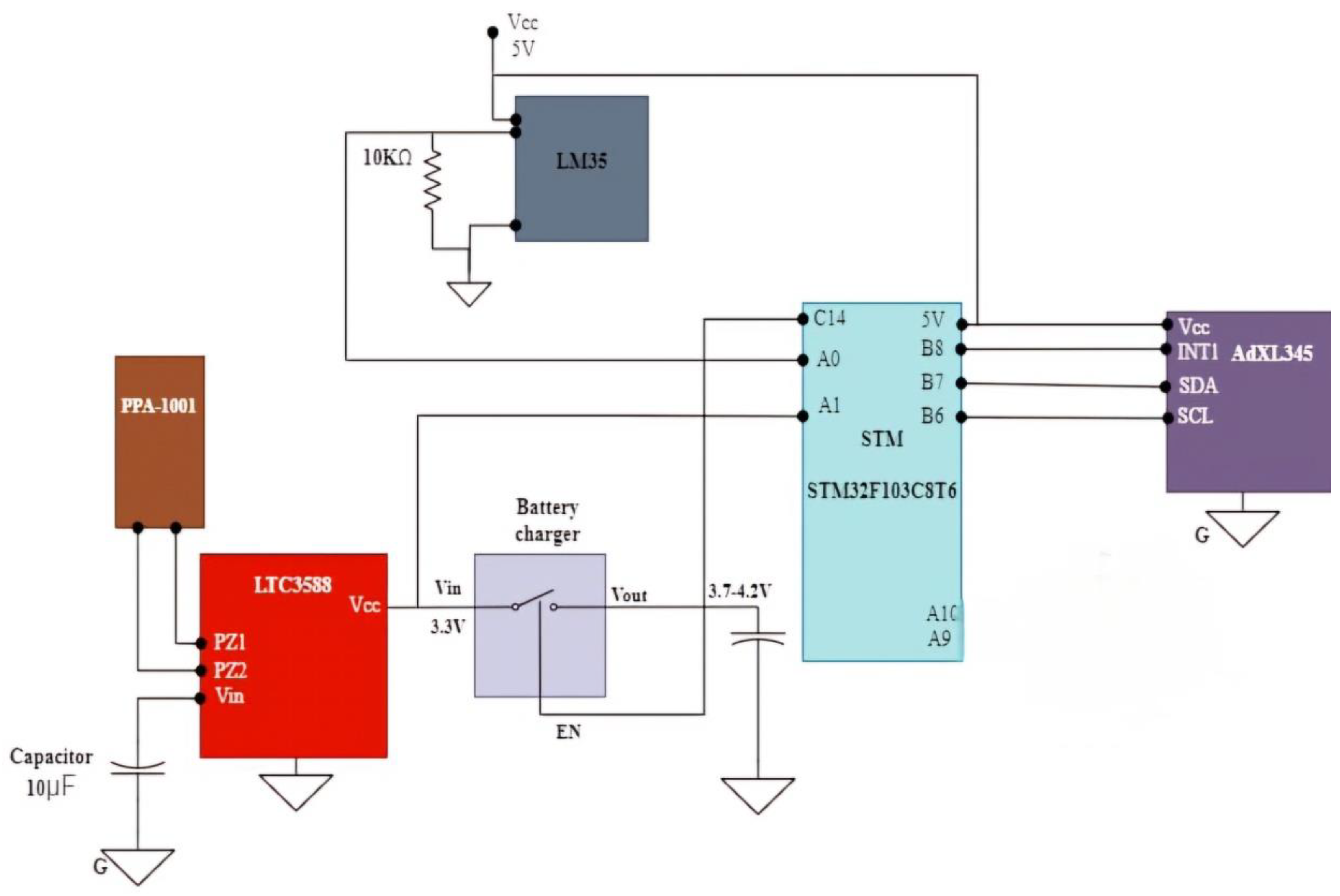
Figure 1 illustrates a complete layout for a vibration electricity harvesting machine, with the PPA-1001 piezoelectric sensor serving because the number one strength supply. The PPA-1001 sensor is strategically located to capture mechanical vibrations from a pipe and convert those vibrations into electric alerts. These alerts are routed to the LTC3588 power harvester, a specialized integrated circuit designed to optimize the low-stage strength produced by the piezoelectric sensor. The LTC3588 correctly regulates and conditions the enter alerts, converting them into a stable 3.3V output, which is essential for the steady operation of downstream electronic components. To further ensure voltage balance, a ten µF capacitor is attached, which enables in smoothing out any fluctuations and reducing voltage ripple. This strong voltage is then fed into a battery charger module, designed to keep an output voltage in the variety of three.7 to 4.2V. This range is specifically crucial because it ensures that the machine remains within secure running limits even as providing enough strength to the connected additives. The charged battery serves as a reliable strength supply, imparting strength to the microcontroller unit (MCU), which in this example is the STM32F103C8T6. The STM32F103C8T6 is an effective and versatile MCU that acts as the central processing unit, coping with the float of information and controlling the gadget's operations.
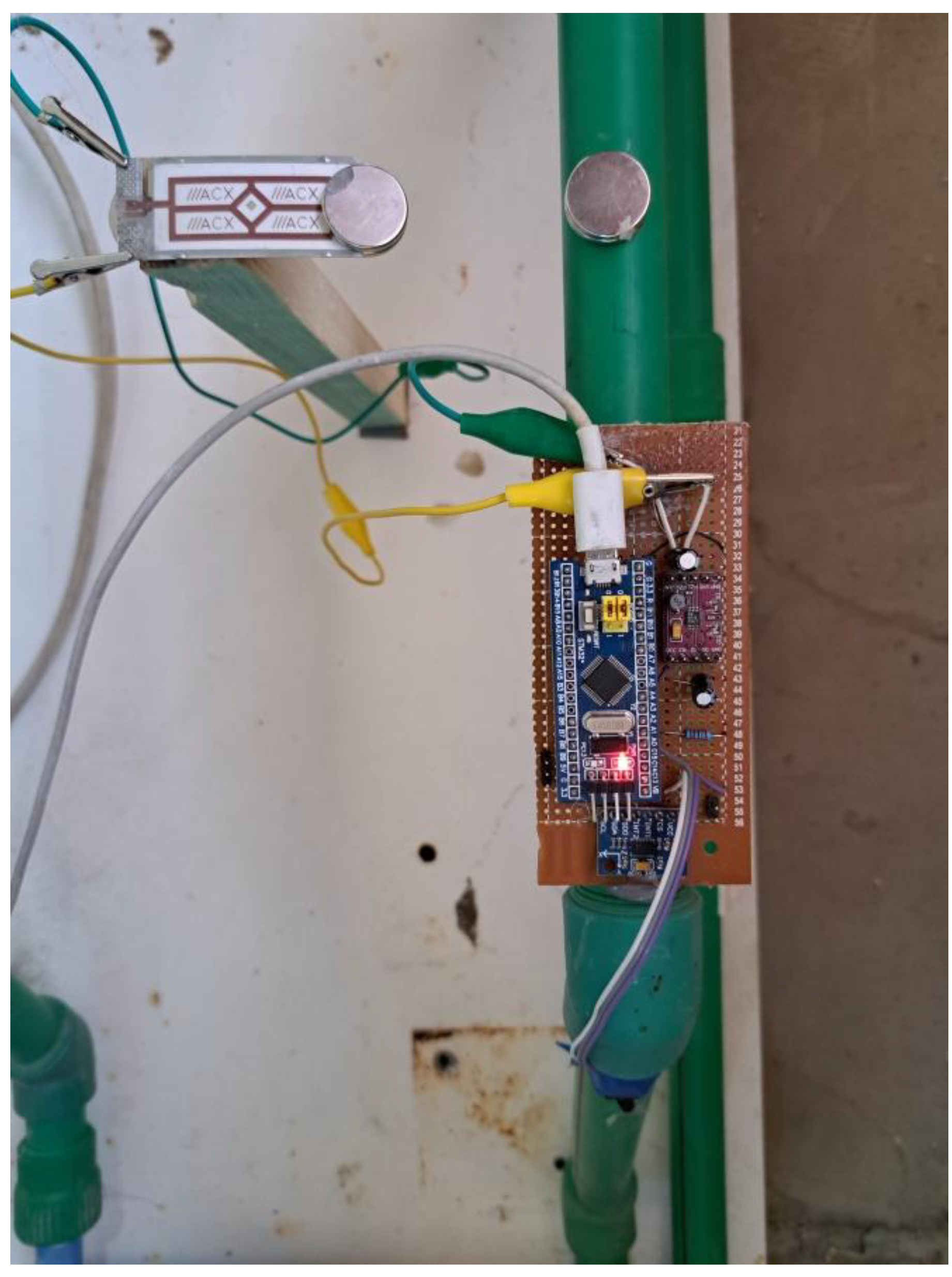
The STM32F103C8T6 is interfaced with the ADXL345 accelerometer thru an I2C interface, which makes use of the SDA (Serial Data) and SCL (Serial Clock) lines for communique. The ADXL345 accelerometer is tasked with measuring the acceleration and vibrations of the pipe, offering actual-time information that is critical for tracking the mechanical conduct of the system. This information is processed through the MCU to determine the device's overall performance and make any vital adjustments. Additionally, the system consists of the LM35 temperature sensor, which is connected to one of the analog inputs of the STM32F103C8T6. The LM35 provides accurate temperature readings of the pipe, which can be crucial for monitoring the thermal conditions that can affect the gadget's performance. The MCU techniques the temperature information alongside the vibration statistics, ensuring comprehensive tracking and manage of the system's operational parameters. The battery, that is constantly charged by way of the harvested strength, guarantees that the gadget stays operational even in the absence of immediately vibrations. This layout guarantees energy sustainability, imparting non-stop electricity to the gadget and permitting it to function efficaciously in far flung or tough environments wherein upkeep and energy supply are constrained .This layout not most effective harvests and stabilizes energy from mechanical vibrations however also integrates specific monitoring and manage mechanisms, making it a robust answer for long-term, independent operation in discipline programs .The assembled designed system is depicted in
Figure 2.
2.3. Software Design Application
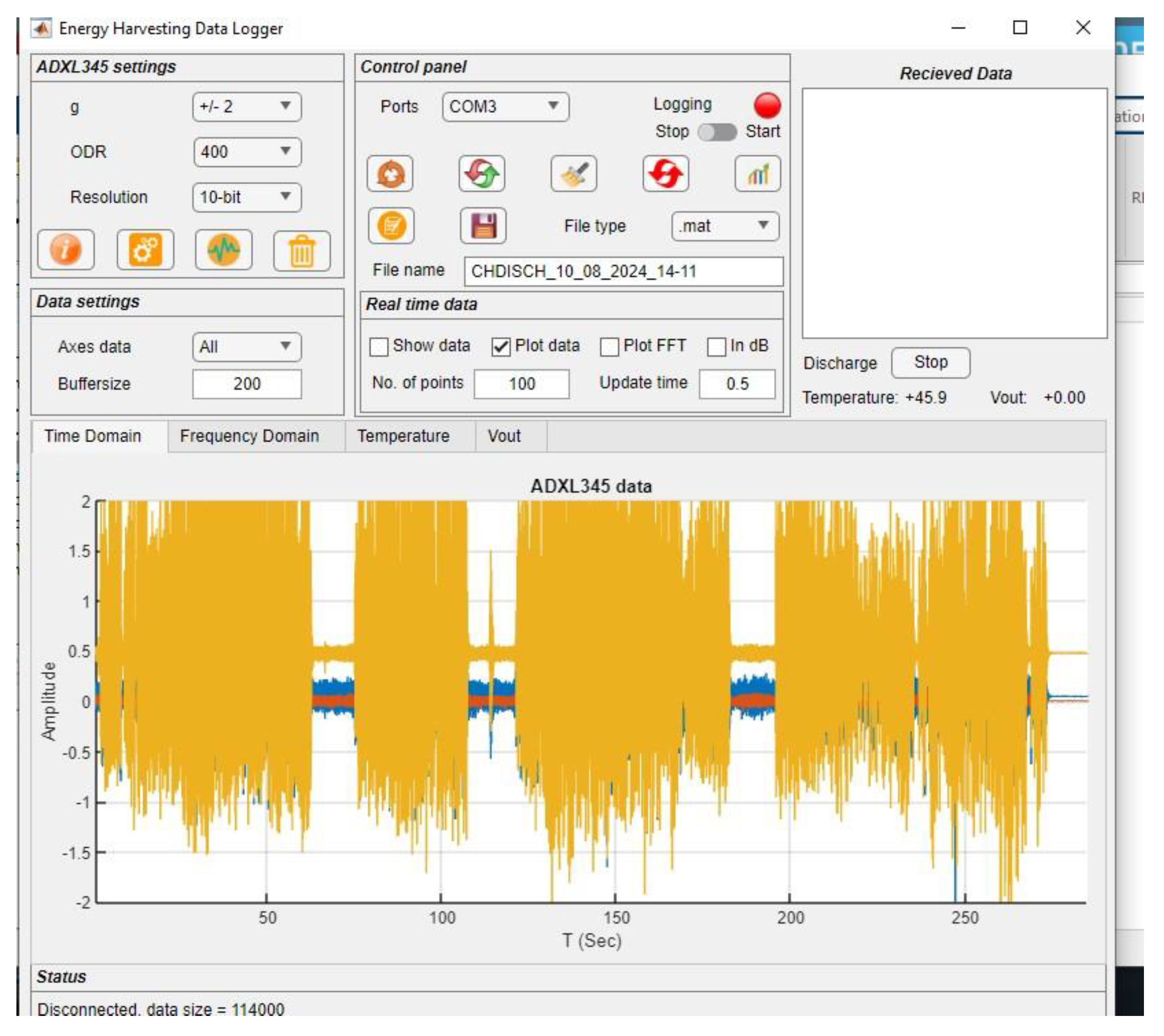
Figure 3. depicts the interface of an "Energy Harvesting Data Logger" application, specifically showing the results of an experiment using the ADXL345 accelerometer. The interface includes several sections:
1. ADXL345 Settings:
The accelerometer is set to a measurement range of ±2g, with a data output rate (ODR) of 400 Hz and a resolution of 10-bit.
2. Control Panel:
The system is configured to log data via COM3, and the file type for saving data is set to mat. The filename indicates the date and time of the experiment (CHDISCH_10_08_2024_14-11).
The control panel also shows the status of the data logging, with options to start or stop the process.
3. Real-Time Data Settings:
The data is plotted in real-time, with options to view the data or its Fast Fourier Transform (FFT) analysis, though FFT is not selected here. The graph updates every 0.5 seconds, showing 100 data points per update.
4. ADXL345 Data Visualization:
The central plot illustrates the accelerometer data over time (T in seconds), with amplitude on the Y-axis. The orange waveform represents the accelerometer readings over a period, showing fluctuations between approximately +1.5g and -1.5g. The data indicates multiple significant vibrational events, with more stable periods in between.
Figure 3 serves as a snapshot of the experimental conditions and the resulting vibrational data captured by the ADXL345 sensor during the energy harvesting experiment. The data appears to show successful detection of vibrational events, which are crucial for analyzing the effectiveness of the piezoelectric energy harvesting system.
2.4. Mechanism of the Work
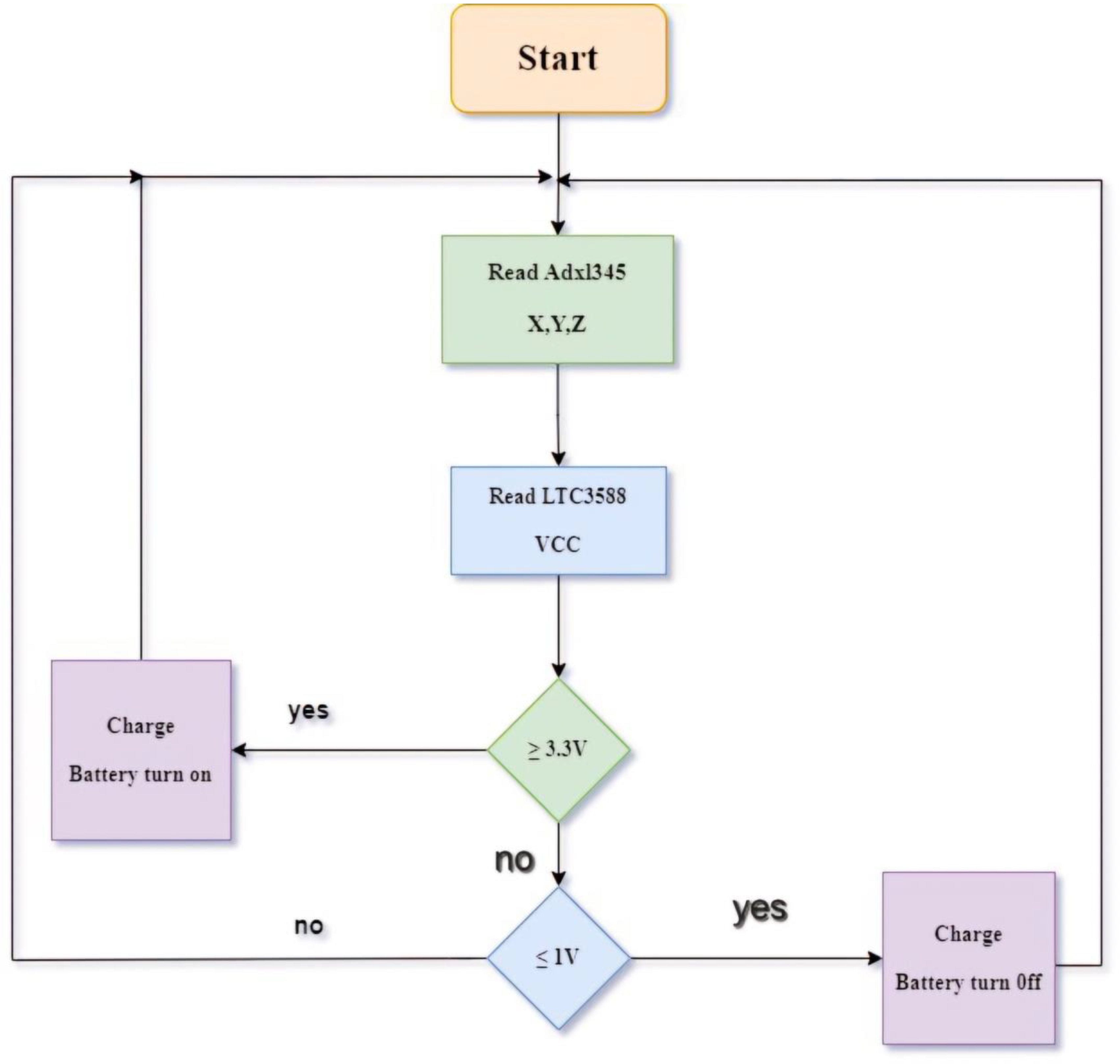
The flowchart in
Figure 4 introduces an in-depth step-by using-step system for dealing with energy harvesting and battery charging in a piezoelectric device. It starts with the machine initializing and right now reading acceleration information from the ADXL345 sensor, which measures the X, Y, and Z-axis vibrations of the pipeline. These measurements are critical as they immediately have an impact on the amount of mechanical power that can be harvested. Following this, the machine reads the voltage output from the LTC3588, a pretty efficient energy harvester that converts the vibrations into electric electricity and regulates the output voltage.
The gadget then compares the harvested voltage in opposition to two crucial thresholds: 3.3V and 1V. If the voltage reaches or exceeds 3.3V, this suggests sufficient electricity has been accumulated, prompting the system to turn on the battery charging manner. This threshold guarantees that the electricity being stored is ok for powering the connected IoT devices and forestalls premature charging that could cause inefficient electricity garages.
If the voltage is much less than 3.3V but still above 1V, the system recognizes that the energy degrees are not the most efficient for charging, so it maintains tracking without starting up the charging technique. This guarantees that the battery is most effectively charged when sufficient power is to be had to avoid partial or inefficient charging cycles. However, if the voltage drops to 1V or beneath, the device routinely turns off the battery charging. This motion prevents the depletion of the saved power and protects the battery from being charged with inadequate power, which could lead to inefficiencies or capability damage. The loop then resets, usually assessing the conditions and responding dynamically to the electricity ranges detected by the system. This smart management ensures that the energy-harvesting gadget operates optimally, holding strength and keeping the longevity and performance of the battery and the overall gadget.
3. Results
The experimental results received from the designed piezoelectric power harvesting device are provided and analyzed. The results are divided into many categories, every highlighting unique elements of the device’s overall performance, along with time-area analysis, frequency-area analysis, temperature version, and the voltage harvested through the piezoelectric sensor.
3.1. Time-Domain Analysis
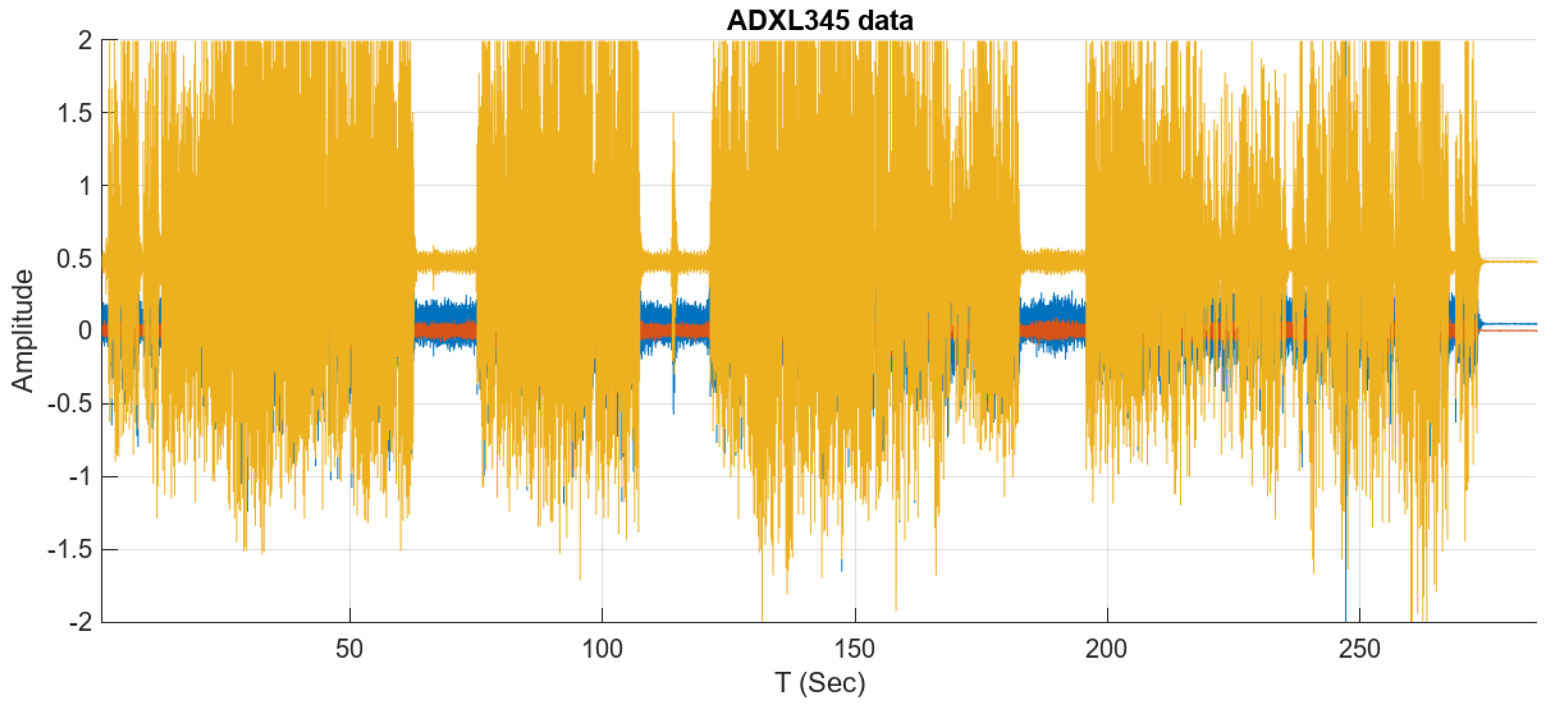
In the time-domain analysis of the extracted data from
Figure 5, the acceleration fluctuates between -2g and +2g, where g represents the acceleration due to gravity (approximately 9.81 m/s²). These values indicate periodic changes within the intensity of vibrations skilled by the pipeline. During durations, while the acceleration reaches +2g, the vibrations are at their top, enhancing the gadget's capacity to generate electrical voltage through the piezoelectric sensor. Conversely, while the acceleration drops to -2g, the vibrations are at their lowest, indicating durations of decreased strength throughout the activity. These normal fluctuations replicate a stable sample within the vibrations, suggesting a constant operation that may be leveraged to optimize the machine for higher strength harvesting performance. Understanding the variations in acceleration is critical for predicting the optimal periods for energy harvesting and making sure continuous power generation despite ongoing changes in vibration intensity.
3.2. Frequency-Domain Analysis
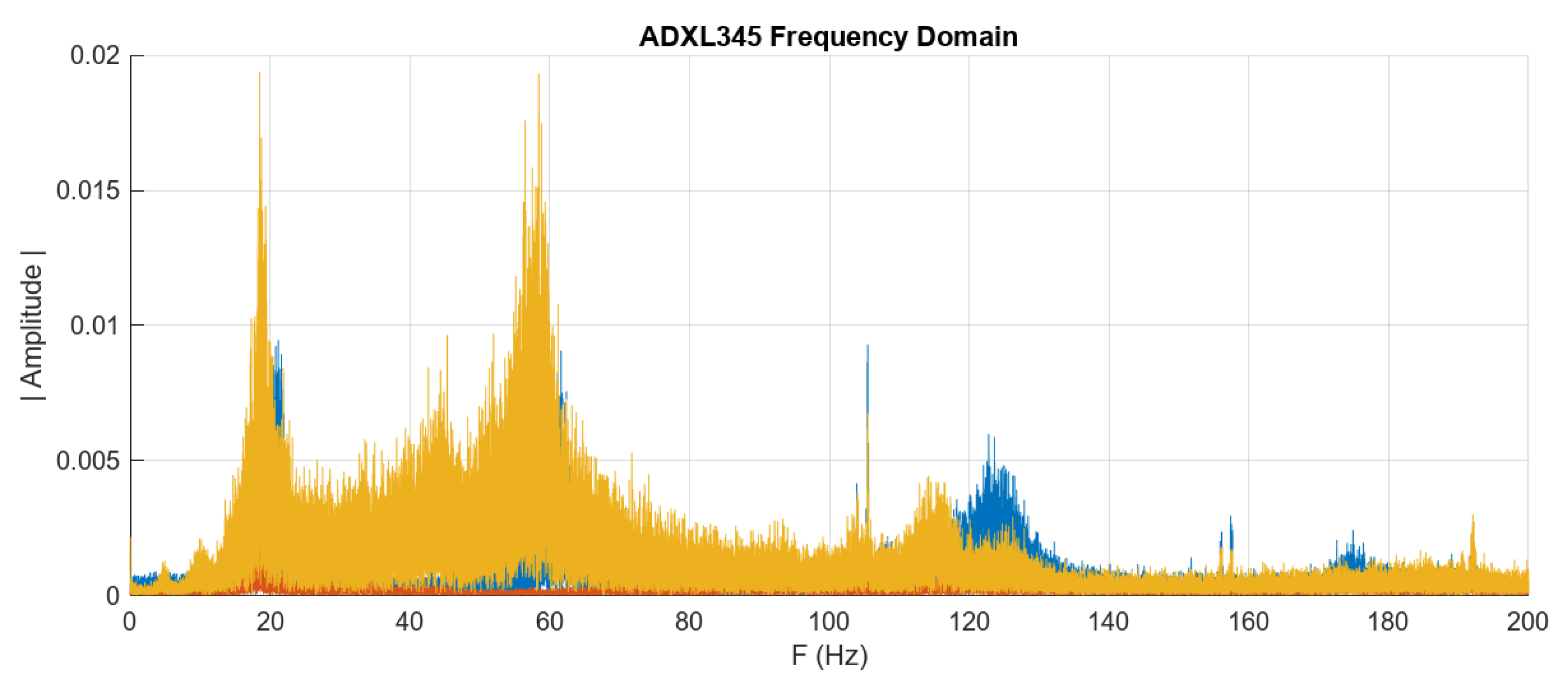
Frequency region analysis was conducted using the Fast Fourier Transform (FFT). The system is maximum green at harvesting power from tube vibrations within a particular frequency varies between 10 Hz to 50 Hz. The consequences displaying that 30 Hz is one of the key frequencies in which the gadget famous first-rate overall performance. At these frequencies, the system is maximum green at changing kinetic energy into electric power, which means that those frequencies match the natural frequency of tube vibrations and are perfect for carrying out maximum power harvesting performance. These consequences replicate the significance of designing the device to function inside this particular frequency range to ensure first-rate ordinary performance in sensible packages.
Figure 6.
Frequency-Domain Analysis.
Figure 6.
Frequency-Domain Analysis.
3.3. Temperature Analysis
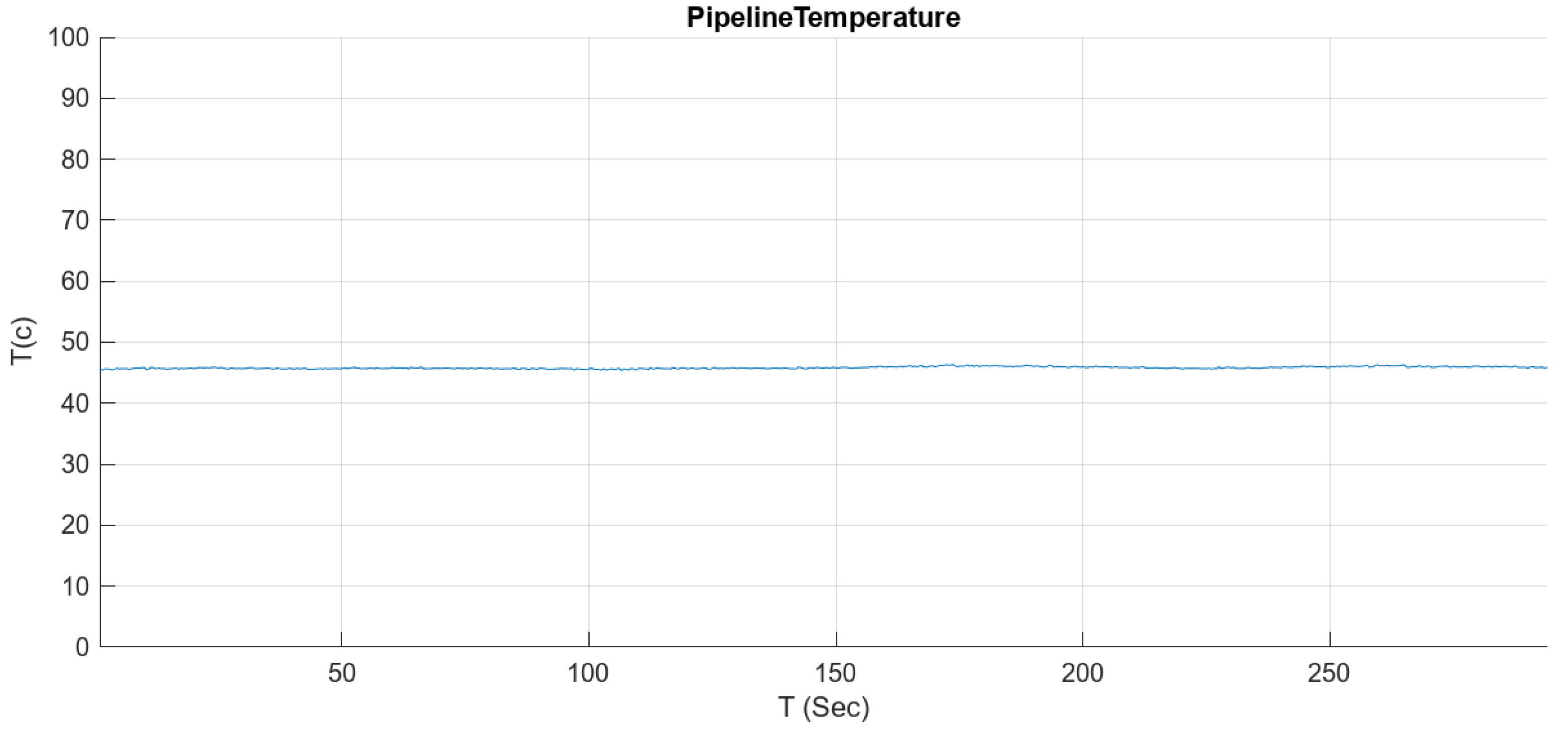
The temperature analysis highlights the piezoelectric electricity harvesting gadget's thermal stability during various temperatures. The LM35 temperature sensor recorded values indicating that the pipeline's temperature fluctuated between 20°C and 35°C during the checking-out duration as proven in
Figure 7. Despite those variations, the harvested voltage remained extraordinarily strong, suggesting that temperature adjustments inside this variety don't appreciably torment the tool's overall performance. This stability is vital for ensuring the reliability of the energy harvesting machine in various environmental situations, in which temperature fluctuations are commonplace. The capability to preserve normal electricity output notwithstanding temperature versions underscores the robustness and sensible applicability of the gadget in actual international pipeline tracking eventualities.
3.4. Voltage and Output Power Acquired from the Sensor
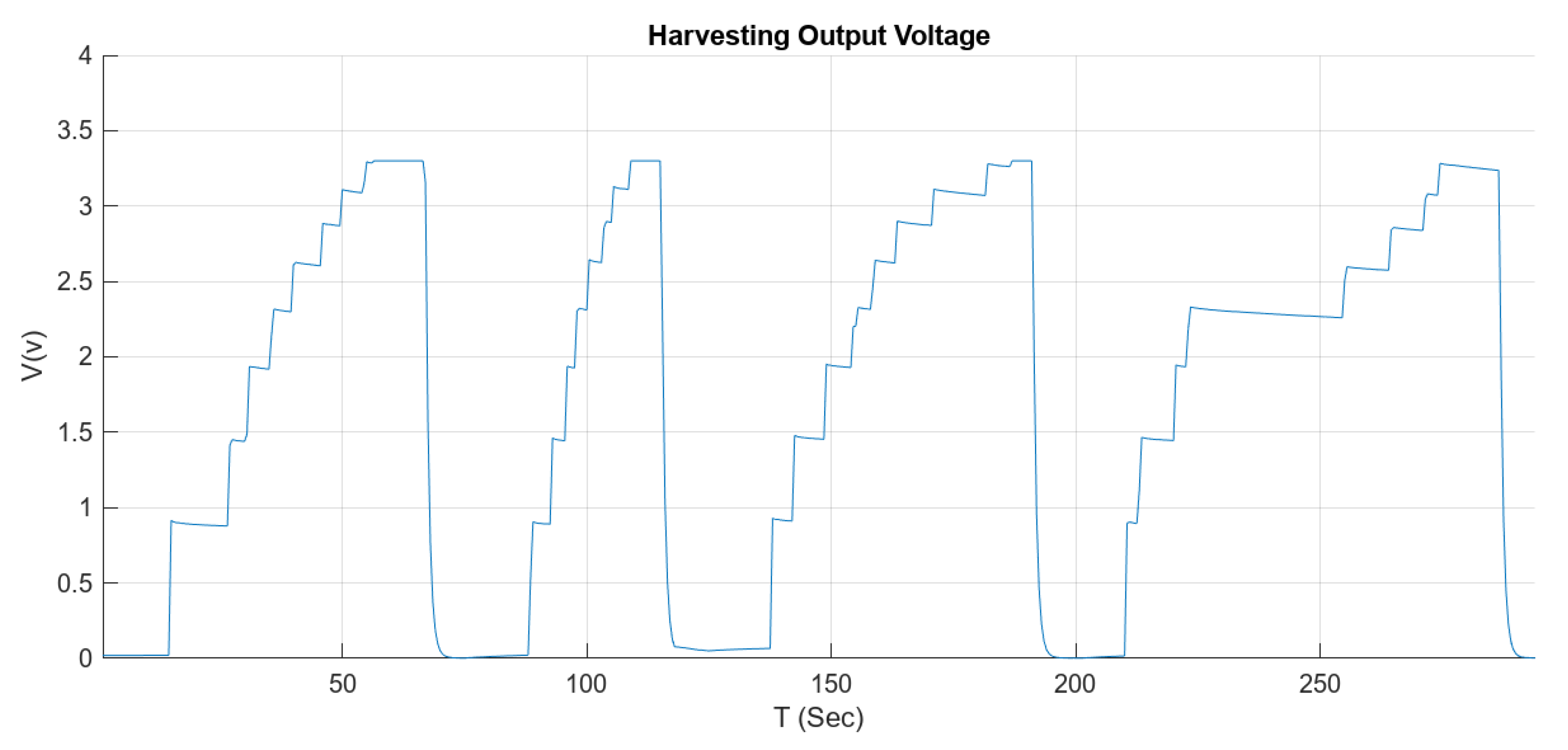
In the gadget analyzed in
Figure 8, the output voltage of the strength harvesting process suggests a clean cyclic sample characterized by way of gradual charging and discharging phases. During the technology procedure, the voltage first of all rises steadily and reaches a most fee of 3.3 V, which represents the maximum energy storage potential of the machine. When this threshold is reached, the gadget enters the discharge segment, the use of the saved strength, resulting in a slow lower in voltage from 3.3 V to 0. This cycle of charging and discharging is repeated over and over, highlighting the performance of the device in changing mechanical vibrations into usable electrical energy. The repeatability of the technique guarantees that electricity is continuously supplied even in fluctuating or intermittent vibration environments, permitting related digital additives to retain to operate.
In this energy harvesting device, the voltage variety is from 0V to 3.3V whilst driving a 5kΩ load. The present day related to this load is zero.66 mA. When the device reaches the most voltage of 3.3V, it gives an energy output of about 2.18mW to the weight. This electricity is received from the mechanical vibrations detected by means of the piezoelectric sensor and transformed into electric power.
The importance of the 2.18 mW output power lies in its capability to electricity low-energy electronics consisting of microcontrollers and sensors. The steady contemporary of 0.66 mA ensures that the strength supplied remains dependable and consistent even when the voltage fluctuates during the electricity manufacturing process. This lets in the system to efficaciously offer a strong energy supply, which is crucial for the continuous operation of linked devices, mainly in environments in which traditional power assets are unavailable or impractical. Therefore, the harvested electricity cannot simplest power the direct load, however also can be stored for later use, thereby improving the overall efficiency and sustainability of the gadget.
4. Discussion
Experimental effects of the piezoelectric energy harvesting system exhibit its great effectiveness in shooting pipeline vibration energy. Time domain evaluation suggests that the voltage generated with the aid of the piezoelectric sensor stays stable through the years, making sure non-stop and dependable powering of linked IoT devices. This stability is critical to maintaining the operation of self-powered devices, particularly in environments in which pipeline vibration is a consistent element. Frequency area analysis also shows that the device is optimized to utilize electricity within a specific frequency variety that coincides with the natural vibration frequency of the pipeline, confirming the layout efficiency of the gadget in actual international applications. In addition, temperature evaluation shows that the system keeps its performance below exceptional temperature conditions, which is important to be used in different environments. The generator’s potential to operate effectively in an extensive variety of thermal situations contributes to its robustness and makes it appropriate for monitoring pipelines in numerous climates. In addition, the voltage output discovered inside the experiments confirmed a right away courting between the depth of the vibration and the energy generated. This correlation highlights the gadget’s ability to correctly power IoT gadgets, especially in conditions wherein pipelines are difficult to robust vibrations.
The effects verify the effectiveness of the piezoelectric electricity harvesting gadget in harnessing pipeline vibration strength and offering a sustainable electricity supply for IoT devices. The device’s adaptability to exceptional frequency and temperature situations suggests its capacity for enormous application inside the field of pipeline monitoring and may assist enhance the safety and performance of industrial procedures.
5. Conclusions
This examination aimed to design and put in force a piezoelectric strength harvesting system capable of harnessing vibrational power from pipelines to bolster IoT devices autonomously. The primary purpose changed to create a sustainable and dependable strength deliver for monitoring structures in environments wherein conventional energy resources are limited or unavailable. The device has superior key components collectively with the PPA-1001 piezoelectric sensor, STM32F103C8T6 microcontroller, and LTC-3588 energy harvesting electricity delivery. The complete layout is examined to evaluate its capacity to seize strength from pipeline vibrations and convert it right into a solid electric output.
The experimental outcomes demonstrated that the system efficiently harvested electricity within a specific frequency variety of 10 Hz to 50 Hz, with premiere performance determined at 30 Hz. The piezoelectric sensor generated a maximum voltage of 3.3V, which powered a load of five kΩ, resulting in a power output of two.18 mW. The system's capacity to maintain stable voltage and power output, even below various temperature conditions (starting from 20°C to 35°C), highlighted its robustness and suitability for actual-world pipeline monitoring programs. The steady power era observed throughout the time-area evaluation further validated the machine's reliability in providing continuous electricity for IoT gadgets.
In addition to reaching the number one goal, this examination affords a foundation for future studies. Potential regions for similar research consist of exploring the scalability of the system for larger pipelines, integrating extra sensors for better monitoring abilities, and optimizing the gadget for extraordinary environmental situations, consisting of extreme temperatures or underwater pipelines. Additionally, future studies ought to attention to enhancing the energy garage and control components to improve the efficiency of the energy delivery for greater worrying IoT applications. This examination contributes to the developing frame of research on energy harvesting technology by using providing a feasible answer for powering IoT gadgets in remote or tough environments. The findings underscore the ability of piezoelectric power harvesting structures to revolutionize pipeline monitoring, supplying a sustainable and self-sustaining energy supply that complements protection and operational efficiency in various business settings.
References
- Y. Shen, X. Liu, C. Liu, H. Guo, X. Yang, and W. Du, “A Low Power Consumption Wireless Sensor System with Wireless Power Harvesting for Oil Pipeline Monitoring,” 2018 Int. Conf. Microw. Millim. Wave Technol. ICMMT 2018 - Proc. 2018, pp. 1–3. [CrossRef]
- C. Xia, W. Liu, and Q. Deng, “Cost Minimization of Wireless Sensor Networks with Unlimited-lifetime Energy for Monitoring Oil Pipelines,” 2015, 2, 290–295.
- W. N. Mohd Fairuz, I. Mohd Nawi, M. R. Ahmad, and R. Kannan, “Experiment and performance analysis of serpentine-shaped cantilever beam for pipeline vibration-based piezoelectric energy harvester prototype development,” Clean Energy, 2024, 8, 111–134. [CrossRef]
- K. Yazawa, Y. Feng, and N. Lu, Conformal heat energy harvester on Steam4 pipelines for powering IoT sensors. Energy Convers. Manag. 2021, 244. [CrossRef]
- B. Usman, S. S. Adamu, and T. Jimoh, “Harvesting Energy From Flow Induced Vibration In Fixed-Fixed And Fixed-Pinned Suported Pipleline : Numerical Approach,” 2019 IEEE PES/IAS PowerAfrica 2019, pp. 458–463.
- F. T. Al Rikabi, S. M. Sargand, J. Kurdziel, and H. H. Hussein, “Pipelines 2019 311,” 2019, 311–320.
- S. Bakhtiar and F. U. Khan, “Energy harvesting from pulsating fluid flow for pipeline monitoring systems,” RAEE 2019 - Int. Symp. Recent Adv. Electr. Eng., 2019, 4, 1–6. [CrossRef]
- W. U. Rahman, “Modeling and Simulation of Flow-Based Circular Plate Type Piezoelectric Energy Harvester for Pipeline ’ s Monitoring,” 2019 22nd Int. Multitopic Conf. 2019, pp. 1–6.
- M. Z. Chaari and R. Rahimi, “Microwave Energy Harvesting Using Rectangular Micro-strip Patch Array Antenna,” 2017, pp. 6–9.
- Abbas, D.T., Hammood, D.A. and Azemi, S.N. Minimizing Energy Consumption Based on Clustering & Data Aggregation Technique in WSN (MECCLADA). Journal of Techniques 2023, 5, 10–19.
- K. B. Flash, “STM32F103x8,” 2023, 1–114.
- U. Manual, “Ppa products”.
- Devices, “ADXL345 (Rev. G),” 2022, 1–36.
- P. By ALLDATASHEETCOM, “LM35 Precision Centigrade Temperature Sensors Literature Number: SNIS159B,” 2000, [Online]. Available online: www.national.com.
- Linear Technology Corporation, “LTC3588-1 - Nanopower Supply Harvesting Power Supply,” http://www.linear.com/product/LTC3588-1. 2011, pp. 1–20. Available online: http://www.analog.com/media/en/technical-documentation/data-sheets/35881fc.pdf.
|
Disclaimer/Publisher’s Note: The statements, opinions and data contained in all publications are solely those of the individual author(s) and contributor(s) and not of MDPI and/or the editor(s). MDPI and/or the editor(s) disclaim responsibility for any injury to people or property resulting from any ideas, methods, instructions or products referred to in the content. |
© 2024 by the authors. Licensee MDPI, Basel, Switzerland. This article is an open access article distributed under the terms and conditions of the Creative Commons Attribution (CC BY) license (http://creativecommons.org/licenses/by/4.0/).
