1. Introduction
Wireless data transmission, with its advantages of low cost, high flexibility, and ease of use, has gained widespread adoption since its inception. As a vital component of IoT services, video data holds significant research importance in ensuring reliable transmission within wireless networks. A recent Cisco report [
1] indicates that mobile video traffic constituted up to 78% of global mobile data traffic in 2021. Video data, composed of a sequence of images, exerts significant pressure on transmission links due to its substantial data volume. Researchers have investigated various strategies to efficiently leverage limited transmission bandwidth for delivering higher quality video. Traditional video compression coding remains the most prevalent solution [
2,
3], but it often necessitates additional redundant coding, which increases computational complexity and introduces further redundancy into the compressed data [
4]. To address the high data volume inherent in video transmission, media practitioners have developed applications that leverage Device-to-Device (D2D) communication to offload cellular network traffic, thereby alleviating the burden on the downlink transmission of operational networks. From this perspective, reference [
5] reported a 30% performance gain for users. References [
6,
7] addressed the uplink allocation challenge for video streams by iteratively optimizing the application layer's bandwidth allocation strategy. This line of research and development aims to circumvent challenges at the operational layer, yet it does not address the underlying issue of excessive data volume. An innovative approach to video transmission involves compressive sensing [
8], which combines data compression and acquisition into a unified process. S. Zheng et al. proposed an efficient video uploading system based on compressive sensing for terminal-to-cloud networks [
9]. L. Li et al. developed a new compressive sensing model and corresponding reconstruction algorithm [
10], creating an image communication system for IoT monitoring applications that addresses sensor node transmission resource constraints. Furthermore, we chose optical wireless communication (OWC) as our transmission medium [
11,
12,
13] because of its advantages, such as high transmission speed, abundant spectrum availability, and strong security features [
14,
15]. N. Cvijetic et al. combined Low-Density Parity-Check (LDPC) coding with channel interleaving in OWC video transmission experiments, evaluating the improvement effects of this coding structure on video transmission [
16]. Z. Hong et al. proposed a residual distribution-based source-channel coding scheme, enhancing the channel error resistance in video transmission, achieving a Bit Error Rate (BER) of 0.0421 in underwater OWC video transmission experiments.
In this paper, we propose an adaptive block sampling compressed sensing algorithm that optimizes the sampling rate allocation mechanism of traditional compressed sensing methods by incorporating image saliency features. Simulation results show that the PSNR of the reconstruction results of this algorithm is generally improved by more than 3 dB compared to other algorithms, with a 1%-6% improvement in Structural Similarity Index (SSIM) metrics. To further verify the performance of the proposed algorithm in optical wireless video transmission, we designed a space optical wireless video transmission prototype based on an FPGA control chip, using the GTP protocol in the Artix-7 series FPGA chips for optical signal transmission, with transmission rates supporting 0.8-6.6 Gbps. The final experimental results show that the PSNR is generally improved by more than 1.5 dB, and the SSIM is improved by more than 1%, demonstrating better optimization of the reconstructed image quality by the proposed algorithm.
2. Design and Principle
The algorithm initially performs block-by-block compressed sensing processing on the input image
with an adaptive sampling rate based on the saliency information of different image blocks. We utilize a fixed-size block and an adaptive block sampling rate mechanism for compressed sensing processing. The traditional block-based compressed sensing algorithm [
17] applies a fixed sampling rate to different blocks. 6. 1 illustrates an example of a natural image divided into 4×4 blocks. The amount of information contained in different blocks in the figure is obviously different. Some blocks contain complex elements such as buildings, clouds, and plants, while most others consist primarily of a simple sky background with minimal data. When different blocks are sampled at a fixed rate, blocks with large amounts of information will be undersampled, leading to insufficient image reconstruction quality, while blocks with less information will be oversampled, resulting in redundant use of storage resources. In the actual block-based compressed sensing algorithm, more image blocks are generated, further amplifying the differences in information content across the blocks.
Figure 1.
Image segmentation diagram.
Figure 1.
Image segmentation diagram.
To enable adaptive sampling across different blocks, this paper introduces saliency information [
18] as the foundation for determining the sampling rate allocation of each block. We proposed an Adaptive Block Sampling (ABS-SPL) compressed sensing algorithm based on the SPL algorithm [
19]. The basic architecture of this approach is illustrated in
Figure 2.
First, we construct a saliency model for the image using a multi-scale spectral residual approach. Spectral Residual (SR) is an analytical method that rapidly detects salient areas of an image by integrating and extracting frequency domain information. The theory posits that the logarithmic spectrum of the spectral amplitude, following the Fourier transform of an image, exhibits a linear distribution trend. This consistent statistical characteristic reflects the image's inherent information redundancy. By removing the similar components of the logarithmic spectrum and retaining the differential information, the salient areas of the image can be effectively identified. The following section outlines the specific implementation steps of the multi-scale residual analysis model.
Given an image
, the Gaussian pyramid method is applied to generate
images of
,
at different scales based on the original image. A Fourier transform is then performed on
to obtain the amplitude spectrum
and the phase spectrum
at these
scales,
A logarithmic operation is performed on the amplitude spectrum
to obtain the logarithmic amplitude spectrum
,
The logarithmic amplitude spectrum
is mean filtered (5×5 filter domain) to obtain
, and then compared with the logarithmic amplitude spectrum
, the spectral residual
at
scales is obtained respectively,
Combine
and
, then perform an inverse Fourier transform to obtain
. Subsequently, apply a Gaussian filter
to
to produce the significant feature maps
at
scales.
The salient feature maps
at different scales are combined using a fusion algorithm to generate the final saliency map
. The fusion weight
is determined by the square of the contrast difference between the salient areas in the saliency feature map and the entire image. Finally, binary segmentation is applied to the final saliency map to obtain templates for salient and non-salient areas, which are then used to allocate compressed sensing sampling rates.
The salient signal of an image represents the amount of information contained within the image, and the quantity of salient signals in each block indicates the distribution of image features. A high distribution of salient pixel signals indicates that the block contains a substantial amount of features, typically corresponding to the textured regions of the image. Conversely, a smaller number of salient pixels represents regions with fewer distinct features, usually corresponding to smoother blocks in block-based compressed sensing. Therefore, the saliency of an image can serve as a metric for pixel activity, with the complexity of the image block's texture quantified by the amount of salient signals. This allows for a reasonable allocation of the sampling rate based on these factors. The following section introduces the specific implementation method of block adaptive sampling.
We conducted experiments using a 256×256 resolution image, with a block size of 16×16 pixels and 256 bytes of information per data block. The image was then sampled based on these parameters.
Let the proportion of salient signals in the image be calculated, and then determine the adaptive sampling rate
for each image block based on the salient image,
Through calculation, the difference
det between the current adaptive sampling rate mean and the total sampling rate is obtained, allowing for the determination of the final sampling rate
,
Here, represents the total sampling rate, denotes the minimum sampling rate threshold, det indicates the difference between the mean adaptive sampling rate and the total sampling rate, and represents the number of image blocks.
To ensure that the adaptive sampling rate does not fall below an acceptable level, the minimum sampling rate threshold is specifically defined as follows,
Based on the sampling rate array
for each block, the size
of the sampling matrix is first determined.
Where is a fixed block size. According to the size of each block sampling matrix, a discrete cosine transform algorithm is used to generate a sparse matrix, and finally a sampling matrix array is generated. The image is compressed based on the sampling matrix, and the final compressed data is obtained by data splicing.
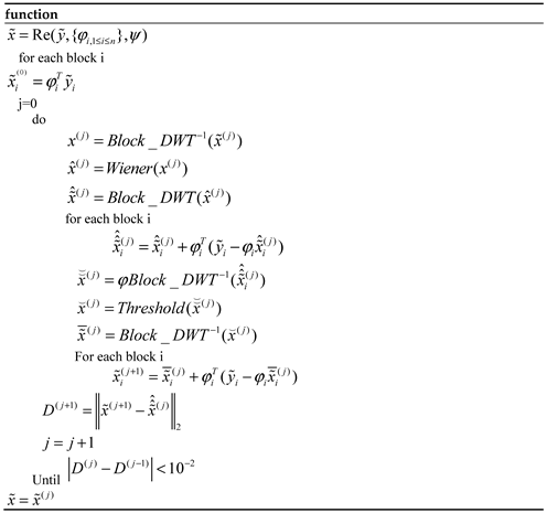
After receiving the data, even if the bytes are not received completely, the receiving end can restore the block grouping of the data through the relative position relationship of the frame header, frame tail and row number to obtain the compressed data . Using the known sampling matrix and sampling rate matrix, the image reconstruction can be completed. The reconstruction algorithm of BCS-SPL couples the complete image Wiener filter smoothing processing with the sparsity enhancement threshold processing in the domain of the complete image sparse transformation, and uses the Landweber method to iterate between smoothing and threshold operations. The reconstruction algorithm in this paper is based on the same principle as BCS-SPL. The Landweber iterative steps are used for blocks at different sampling rates, and the measurement matrix based on the current block is used. The specific reconstruction process is as follows:
Table 1.
Adaptive block sampling compressed sensing image reconstruction process.
Table 1.
Adaptive block sampling compressed sensing image reconstruction process.
The aforementioned calculation process represents a 2D image reconstruction algorithm based on adaptive sampling rate block compressed sensing. In this context, Wiener(.) refers to a Wiener filter that adapts pixel-by-pixel using a 3×3 neighborhood, while Threshold(.) denotes the threshold processing within the BCS-SPL algorithm. The application of this algorithm results in the accurate reconstruction of the image.
3. Results
3.1. Simulation Analysis
We utilize the SPL algorithm, the 2DCS algorithm, and the MS-SPL-DDWT algorithm as benchmarks for comparison. The SPL algorithm, a classical block compressed sensing approach, combines Wiener smoothing with Landweber iteration, offering superior processing performance. The 2DCS algorithm [
20] is an encryption-then-compression (ETC) approach that enhances the error correction capability of reconstruction through its encryption process. In addition to enhancing the confidentiality of information transmission, it also significantly optimizes the overall quality of the reconstructed image. The MS-SPL algorithm [
21] allocates appropriate sampling rates to the wavelet coefficients of images at different scales, significantly enhancing the reconstruction quality compared to previous methods. We selected these three algorithms for comparison with the algorithm proposed in this paper, utilizing peak signal-to-noise ratio (PSNR), structural similarity (SSIM), gradient magnitude similarity deviation (GMSD), and normalized root mean square error (NMSE) as evaluation metrics. The peak signal-to-noise ratio (PSNR) [
22] measures the peak error between the reconstructed image data and the original image data, quantifying the peak signal-to-noise ratio between the two images. The structural similarity index (SSIM) [
23] evaluates the similarity between the reconstructed image and the original image by considering three key aspects: brightness, contrast, and structure. Elevated values of these two parameters reflect an improved quality of image reconstruction. The normalized root-mean-square error (NMSE) [
24] and gradient magnitude similarity deviation (GMSD) [
25] serve as error metrics that quantify the discrepancies between the original and reconstructed images. Lower values for these two metrics indicate a better reconstruction quality. After conducting simulations, the test results are as follows.
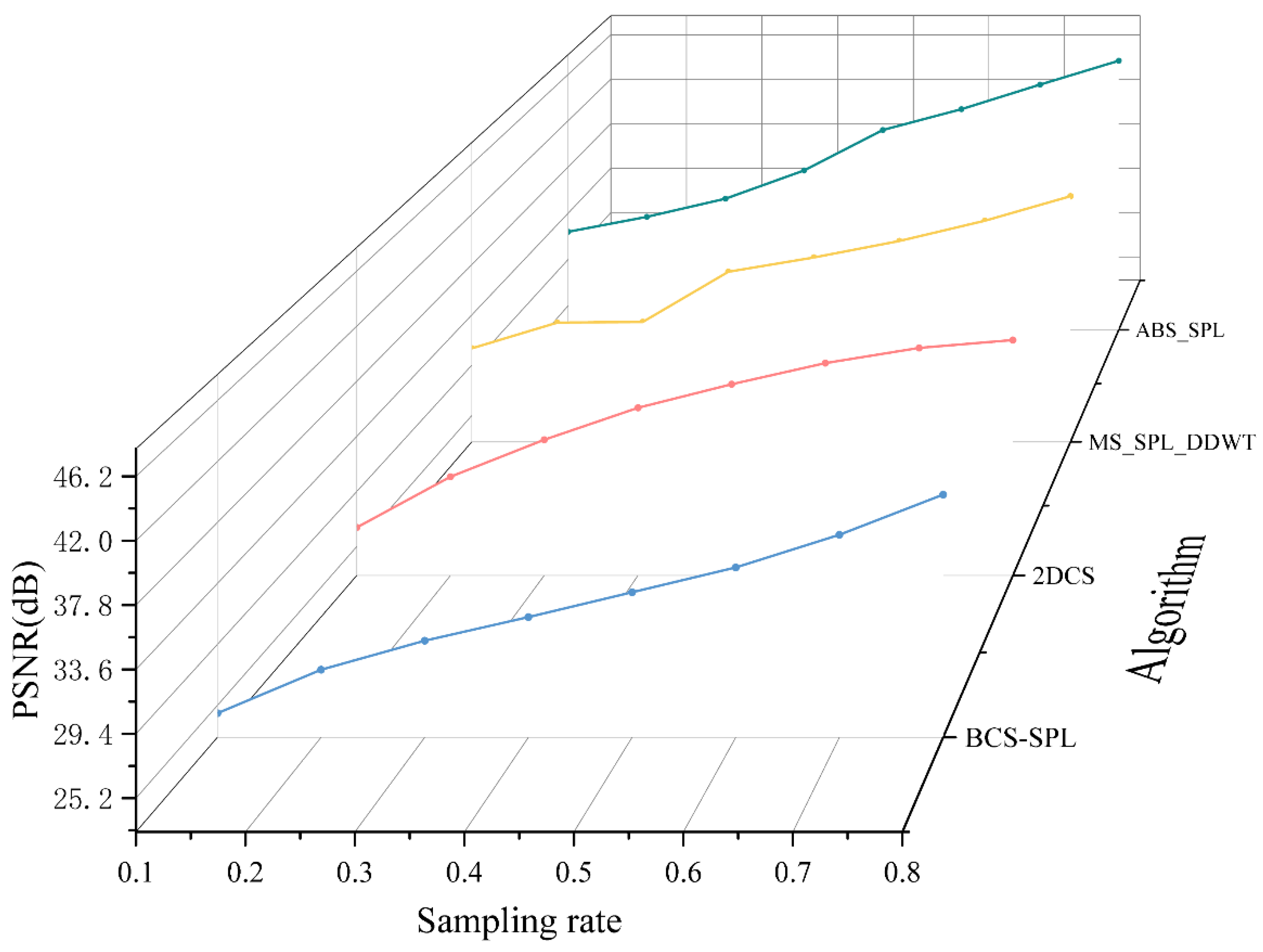
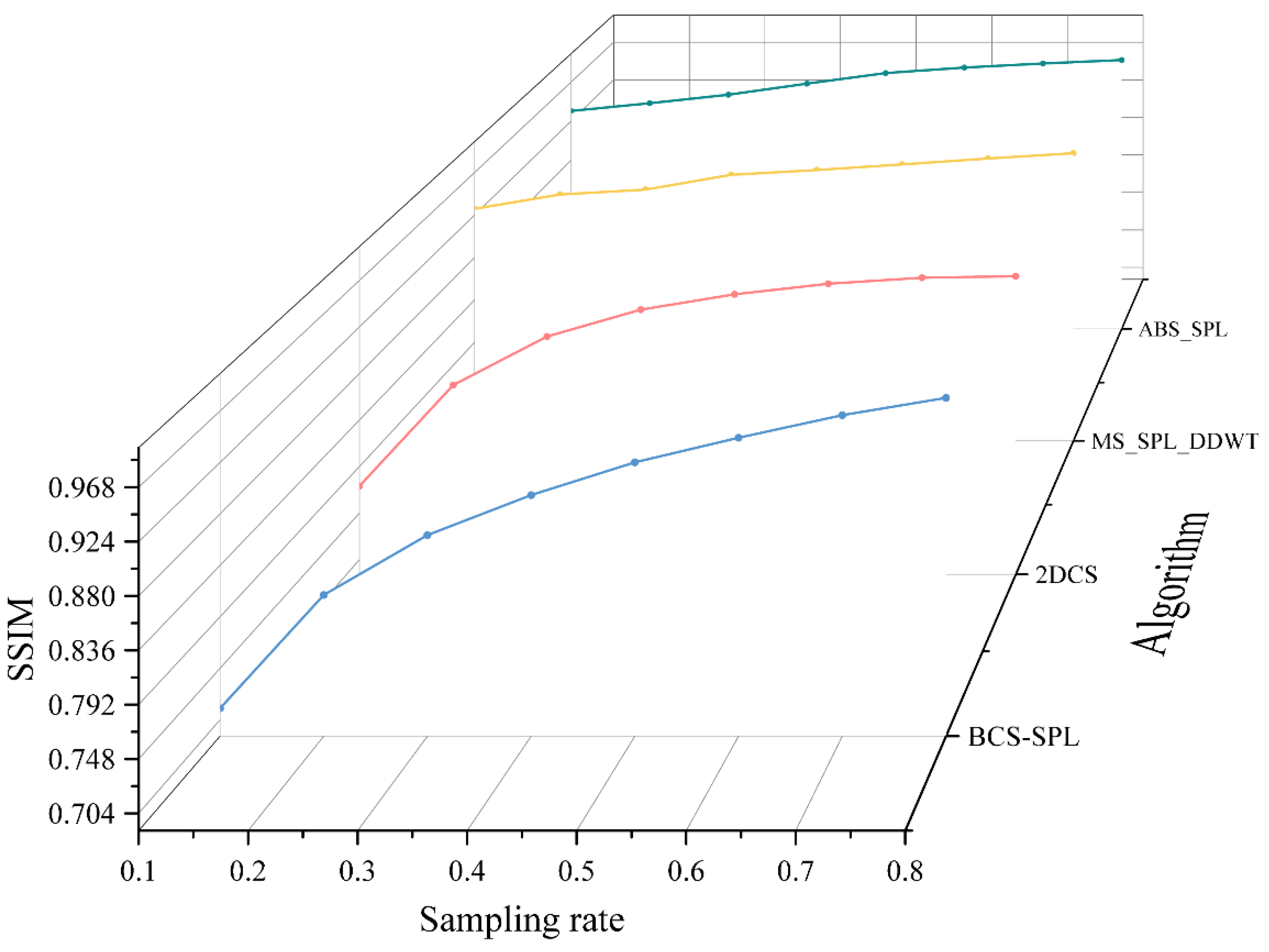
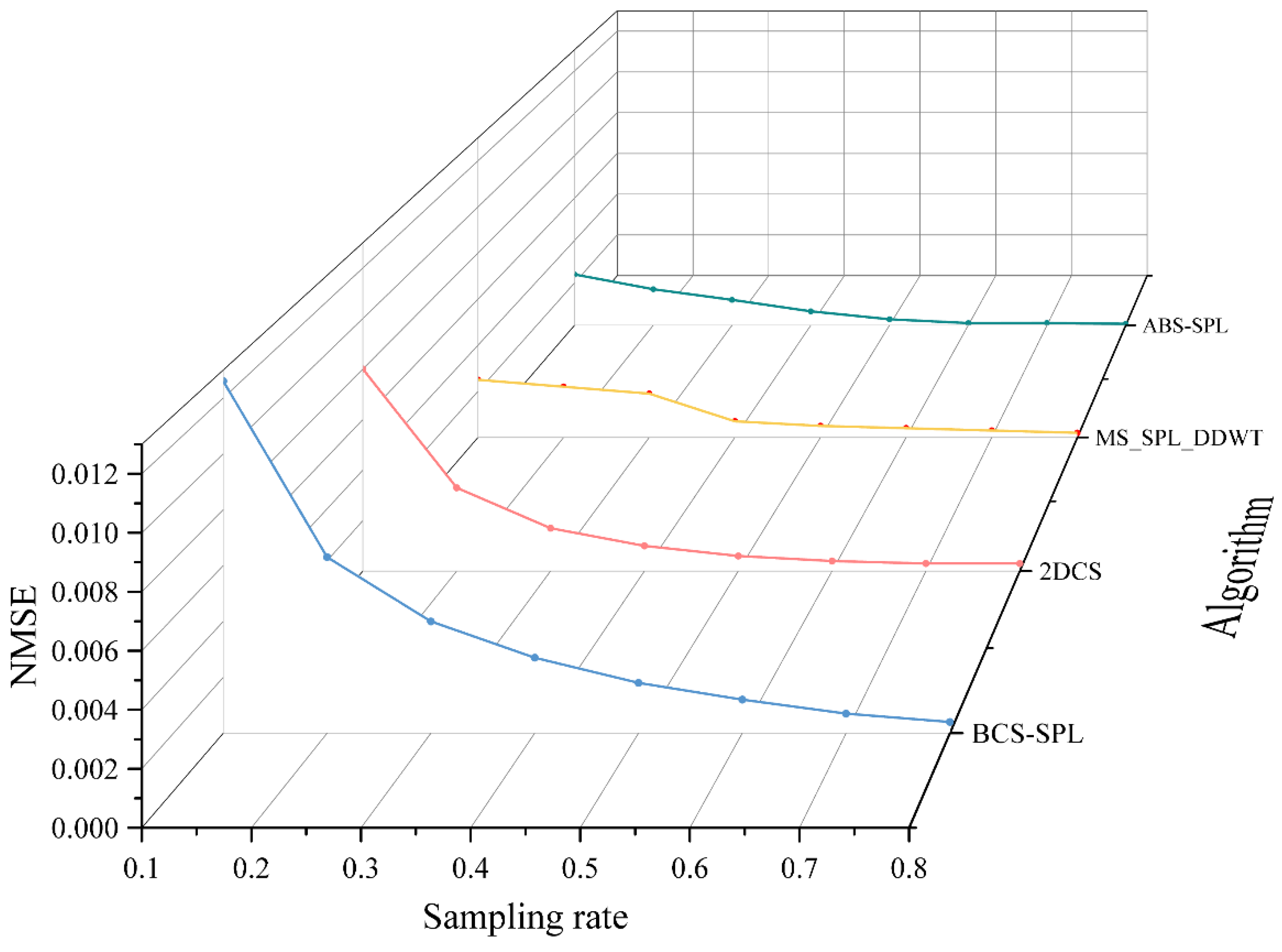
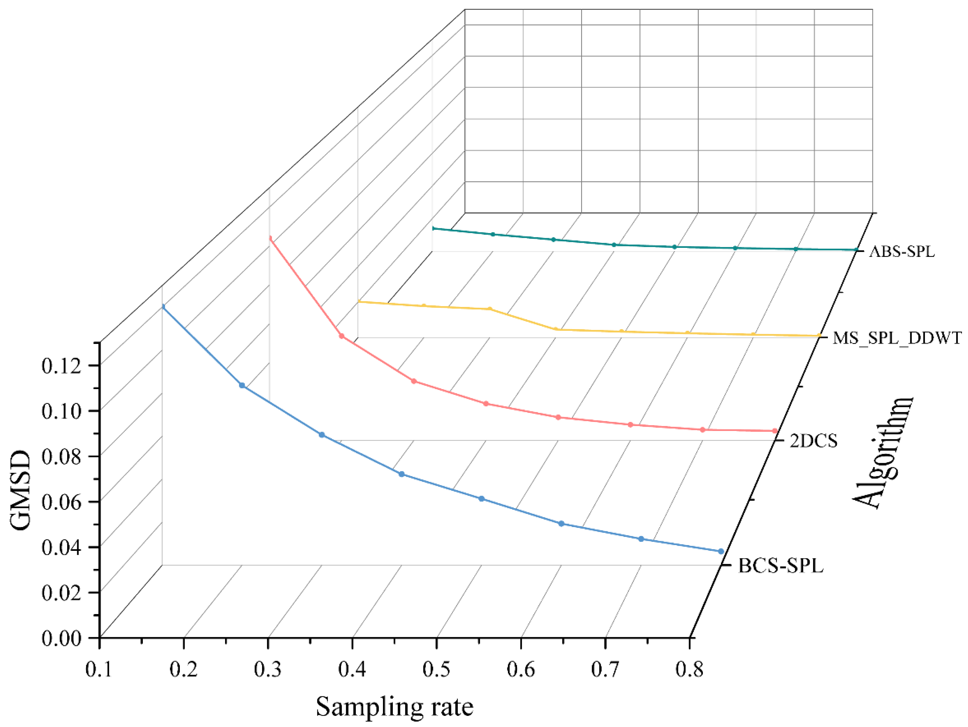
As illustrated in
Figure 4,
Figure 5,
Figure 6 and
Figure 7, using a sampling rate of 0.5 as an example, the PSNR of the reconstruction result achieved by the algorithm proposed in this paper exceeds 41 dB, which is approximately 3 dB higher than that of other algorithms. From the perspective of the SSIM index, the reconstruction result of the algorithm proposed in this paper is slightly higher than that achieved by the MS-SPL algorithm. The results of these two algorithms are close to 98%, which is over 2% higher than those of the other algorithms. Regarding the two error parameters, NMSE and GMSD, in the low sampling rate range (0.1-0.3), the algorithm proposed in this paper outperforms other algorithms significantly, with error rates generally 1%-6% lower than those of the other methods. As the sampling rate increases, the reconstruction results of the MS-SPL algorithm gradually converge, but its error remains slightly higher than that of the algorithm proposed in this paper. Analysis indicates that the algorithm proposed in this paper offers substantial enhancements in image reconstruction quality, particularly at lower sampling rates. By efficiently allocating sampling rates across different blocks, the algorithm improves data utilization efficiency and assigns higher subsampling rates to blocks containing more complex scenes.
3.2. Optical Wireless Video Transmission Experiment
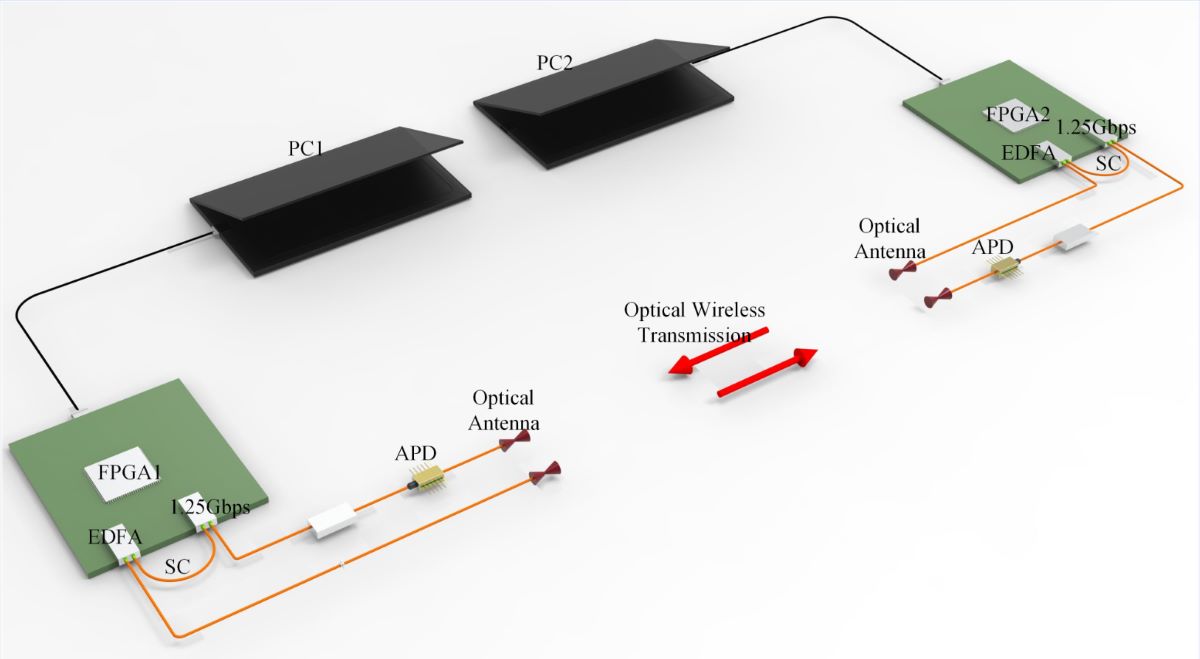
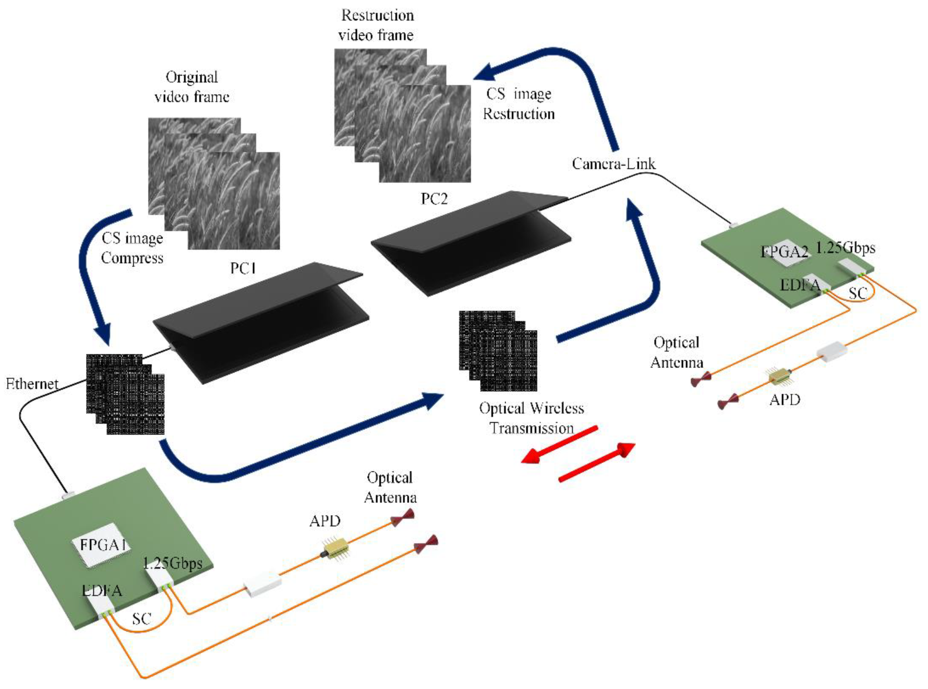
We utilized the Artix-7 series FPGA chip as the processor to design a spatial optical wireless video transmission system. As depicted in
Figure 8, the compressed sensing algorithm is first employed on the PC to process the image sequence on a frame-by-frame basis. Subsequently, the compressed image sequence is transmitted to the device transmitter as a video stream via Camera-Link. After the FPGA captures the video stream frame by frame, the image data is internally cached and encoded. The optoelectronic transceiver module (Small Form Pluggable, SFP) subsequently converts the electrical signal into an optical signal. This optical signal is then amplified by an erbium-doped fiber amplifier (EDFA) before being transmitted through the optical system. At the receiving end, an APD detector module serves as the optical signal receiver. The collected optical signal is conveyed to the SFP optical module on the receiving FPGA board via the optoelectronic conversion module. The FPGA then converts the image into a Camera-Link video stream, which is sent to the PC for frame-by-frame reconstruction. Ultimately, the reconstructed image sequence is compiled into a video. We utilized the Artix-7 series 7a100t-fgg484 model FPGA as the main control chip and set the GTP transmission rate to 1.25 Gbps for the experiment. To ensure the equipment's lightness and miniaturization, we opted for a highly integrated modular EDFA (BG-EDFA-M3-C1-N-15dBm, 0.95M-1m-FC/APC). For the APD module, we selected the LSIAPDT-S200 InGaAs APD detector, which offers superior response at the 1550 nm wavelength. The optical system incorporated a transmissive optical antenna with a 1550 nm communication band and a 25 mm aperture.
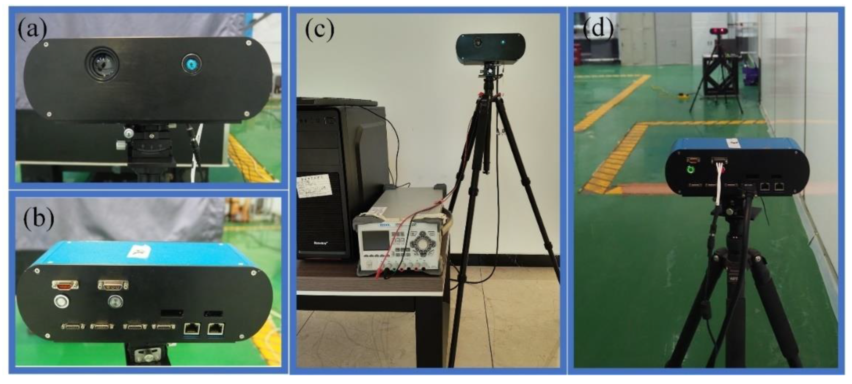
Figure 9 depicts the spatial optical wireless video transceiver prototype constructed based on the design principles outlined in
Figure 8, which was used to conduct a dual-end video data transmission experiment in an atmospheric environment.
Figure 9a presents the overall front view of the device, while
Figure 9b illustrates the external interface from the rear.
Figure 9c,d provide schematic representations of the device connections during the spatial optical wireless video transceiver experiment. The device is equipped with GTP high-speed transceivers, an RJ45 Gigabit Ethernet interface, and an SDR26 Camera-Link video transceiver interface. The optical signal transceiver supports rates ranging from 0.8 to 6.6 Gbps, thereby fulfilling the requirements for processing and converting spatial optical wireless video transceiver input from various interfaces.
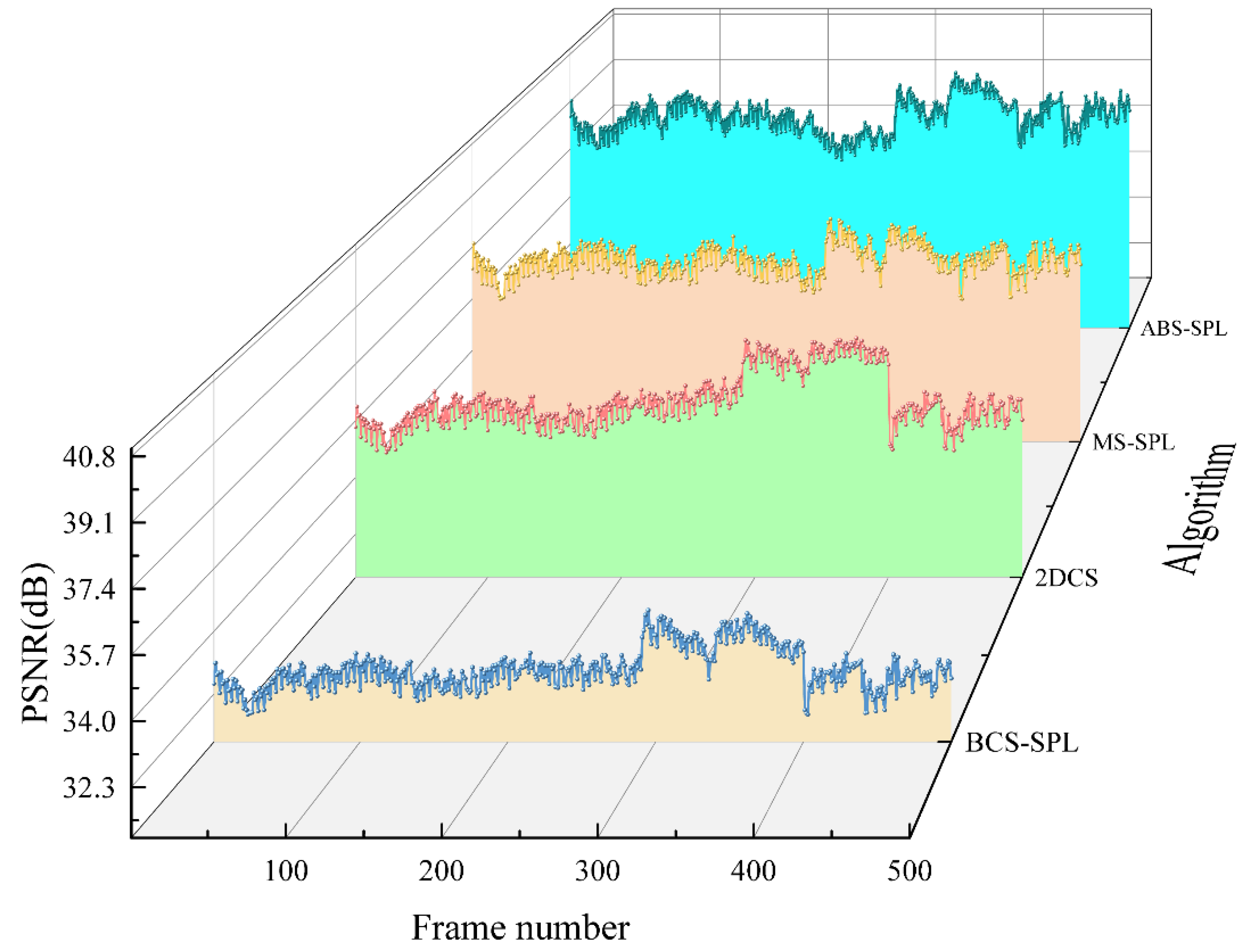
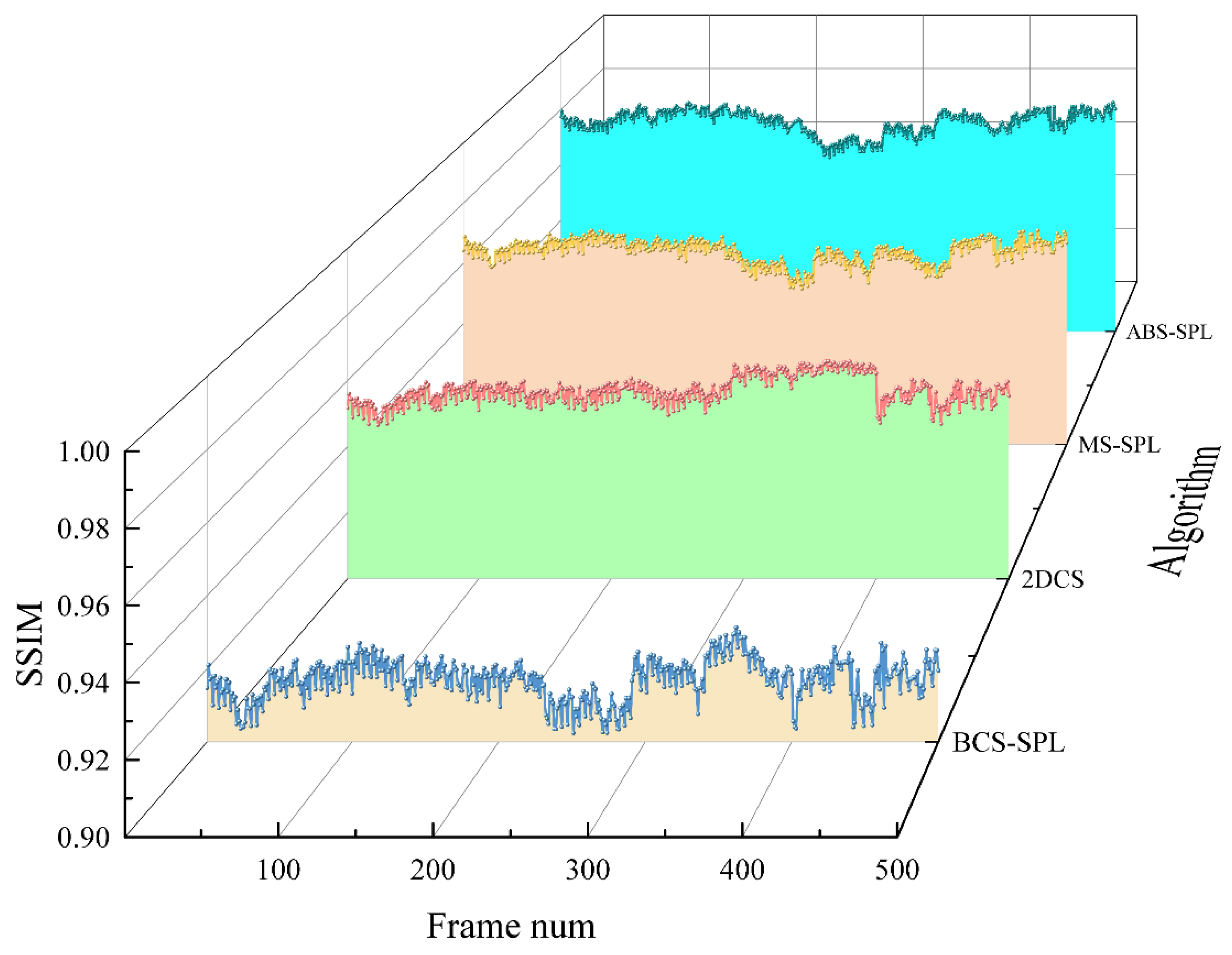
A video sequence consisting of 500 frames was captured and processed using the four algorithms previously compared on the PC. A spatial optical wireless video transmission experiment was then conducted over a terminal distance of 20 meters. Following calibration, a spatial optical power meter was used to measure the transmitter's optical power, which was recorded as 9.3 dBm, while the APD receiver's optical power was measured at -24.7 dBm. The sampling rate for the compressed sensing algorithm was uniformly set to 0.5, and the PSNR and SSIM metrics of the reconstruction results were statistically analyzed on a frame-by-frame basis. The experimental results are presented in
Figure 10 and
Figure 11.
Figure 10 demonstrates that the proposed algorithm performs effectively in spatial optical wireless video transmission, with its reconstruction results showing a PSNR generally more than 1.5 dB higher than those of the other algorithms. Similarly,
Figure 11 indicates that the proposed algorithm achieves SSIM values that are generally over 1% higher than those of the comparison algorithms, thereby delivering superior video reception quality.
4. Summary and Discussion
This paper introduces a compressed sensing algorithm with an adaptive block sampling rate, wherein the sampling rate for each block is determined based on the proportion of significant information within the image blocks. This method enhances the quality of compressed sensing reconstructed images while maintaining the same data volume. Evaluation using image quality metrics reveals improvements of over 3 dB in PSNR and more than 2% in SSIM. Additionally, the NMSE and GMSD metrics are reduced by 1% to 6%. A spatial optical wireless video transceiver system, based on an FPGA master chip, was designed, and natural target video transmission experiments were conducted using 500 frames of image sequences processed by the proposed algorithm. The experimental results demonstrate that the algorithm maintains superior image transmission performance in spatial optical wireless video transmission, with PSNR improved by more than 1.5 dB and SSIM by over 1%. Furthermore, the spatial optical video transmission system developed in this study exhibits excellent integration and cost efficiency, offering significant practical and commercial value.
Author Contributions
Conceptualization, J.L. and H.Y.; methodology, J.L.; software, J.L.; validation, J.L., Z.C. and W.W.; formal analysis, H.Y.; investigation, Y.Z.; resources, K.D.; data curation, J.L.; writing—original draft preparation, J.L.; writing—review and editing, J.L.; visualization, Y.S.; supervision, H.Y.; project administration, Z.L.; funding acquisition, K.D. All authors have read and agreed to the published version of the manuscript.
Funding
This research was funded by the National Natural Science Foundation of China, NSFC, U2141231, 62105029, the Youth Talent Support Program of China Association for Science and Technology, CAST, No.YESS20220600, the National Key R&D Program of China, Ministry of Science and Technology, 2021YFA0718804, 2022YFB3902500, and the Major Science and Technology Project of Jilin Province, 20230301002GX, 20230301001GX.
Institutional Review Board Statement
Not applicable
Informed Consent Statement
Not applicable
Data Availability Statement
The data underlying the results presented in this paper are not publicly available at this time but may be obtained from the authors upon reasonable request.
Acknowledgments
We would like to extend our sincere gratitude towards Changchun University of Science and Technology, Beijing Institute of Technology, the National Natural Science Foundation of China (NSFC), the Youth Talent Support Program of China Association for Science and Technology (CAST), the National Key R&D Program of China, Ministry of Science and Technology and the Major Science and Technology Project of Jilin Province for their support.
Conflicts of Interest
All The authors declare no conflict of interest.
References
- “Cisco visual networking index: Global mobile data traffic forecast update, 2016–2021,” White Paper, 2017.
- Fan, D.; Zhao, H.; Zhang, C.; Liu, H.; Wang, X. Anti-Recompression Video Watermarking Algorithm Based on H.264/AVC. Mathematics 2023, 11, 2913. [CrossRef]
- L. Yang, R. Wang, D. Xu, L. Dong and S. He, "Centralized Error Distribution-Preserving Adaptive Steganography for HEVC," in IEEE Transactions on Multimedia. [CrossRef]
- D. K. J. B. Saini, S. D. Kamble, R. Shankar, M. R. Kumar, D. Kapila, D. P. Tripathi, and Arunava de, “Fractal video compression for IOT-based smart cities applications using motion vector estimation,” Measurement: Sensors. Volume 26, 100698(2023).
- C. Zhan, H. Hu, Z. Wang, R. Fan and D. Niyato, "Unmanned Aircraft System Aided Adaptive Video Streaming: A Joint Optimization Approach," in IEEE Transactions on Multimedia, vol. 22, no. 3, pp. 795-807, March 2020, . [CrossRef]
- He, C.; Xie, Z.; Tian, C. A QoE-Oriented Uplink Allocation for Multi-UAV Video Streaming. Sensors 2019, 19, 3394. [CrossRef]
- R. Yamada, H. Tomeba, T. Sato, O. Nakamura and Y. Hamaguchi, "Uplink Resource Allocation for Video Transmission in Wireless LAN System," 2022 IEEE 8th World Forum on Internet of Things (WF-IoT), Yokohama, Japan, 2022, pp. 1-6, . [CrossRef]
- D. L. Donoho, "Compressed sensing," in IEEE Transactions on Information Theory, vol. 52, no. 4, pp. 1289-1306, April 2006. [CrossRef]
- S. Zheng, X. -P. Zhang, J. Chen and Y. Kuo, "A High-Efficiency Compressed Sensing-Based Terminal-to-Cloud Video Transmission System," in IEEE Transactions on Multimedia, vol. 21, no. 8, pp. 1905-1920, Aug. 2019. [CrossRef]
- L. Li, G. Wen, Z. Wang and Y. Yang, "Efficient and Secure Image Communication System Based on Compressed Sensing for IoT Monitoring Applications," in IEEE Transactions on Multimedia, vol. 22, no. 1, pp. 82-95, Jan. 2020, . [CrossRef]
- Chowdhury, M.Z.; Shahjalal, M.; Hasan, M.K.; Jang, Y.M. The Role of Optical Wireless Communication Technologies in 5G/6G and IoT Solutions: Prospects, Directions, and Challenges. Appl. Sci. 2019, 9, 4367. [CrossRef]
- Haas H, Elmirghani J, White I. 2020 Optical wireless communication. Phil. Trans. R. Soc. A 378: 20200051. [CrossRef]
- Tavakkolnia, I. Jagadamma, L. K. Bian, et al. Organic photovoltaics for simultaneous energy harvesting and high-speed MIMO optical wireless communications. Light Sci Appl 10, 41 (2021). [CrossRef]
- H. Yao, X. Ni, C. Chen, B. Li, X. Zhang, Y. Liu, S. Tong, Z. Liu, and H. Jiang, “Performance of M-PAM FSO communication systems in atmospheric turbulence based on APD detector,” Opt. Express 26, 23819-23830 (2018).
- Gong-Ru Lin, Hao-Chung Kuo, Chih-Hsien Cheng, Yi-Chien Wu, Yu-Ming Huang, Fang-Jyun Liou, and Yi-Che Lee, "Ultrafast 2 × 2 green micro-LED array for optical wireless communication beyond 5 Gbit/s," Photon. Res. 9, 2077-2087 (2021).
- N. Cvijetic, S. G. Wilson and R. Zarubica, "Performance Evaluation of a Novel Converged Architecture for Digital-Video Transmission Over Optical Wireless Channels," in Journal of Lightwave Technology, vol. 25, no. 11, pp. 3366-3373, Nov. 2007, . [CrossRef]
- L. Gan, T. T. Do, and T. D. Tran, “Fast compressive imaging using scrambled block Hadamard ensemble,” in Proceedings of the European Signal Processing Conference, Lausanne, Switzerland, August 2008.
- Zhu, Y.; Liu, W.; Shen, Q. Adaptive Algorithm on Block-Compressive Sensing and Noisy Data Estimation. Electronics 2019, 8, 753. [CrossRef]
- Sungkwang Mun,James E.Fowler. Block compressed sensing of images using directional transforms[J].2009 16th IEEE International Conference on Image Processing (ICIP)11151201.
- B. Zhang, D. Xiao, Z. Zhang, and L. Yang, “Compressing Encrypted Images by Using 2D Compressed Sensing,” 2019 IEEE 21st International Conference on High Performance Computing and.
- J. E. Fowler, S. Mun and E. W. Tramel, "Multiscale block compressed sensing with smoothed projected Landweber reconstruction," 2011 19th European Signal Processing Conference, Barcelona, Spain, 2011, pp. 564-568.
- D. Poobathy, R. M. Chezian, " Edge Detection Operators: “Peak Signal to Noise Ratio Based Comparison,” in I. J. Image, Graphics and signal processing, pp. 55-61 (2014).
- Z. Wang, A. C. Bovik, H. R. Sheikh and E. P. Simoncelli, “Image quality assessment: from error visibility to structural similarity,” in IEEE Transactions on Image Processing, vol. 13, no. 4, pp. 600-612(2004).
- J. Pęksiński, G. Mikołajczak, “The Synchronization of the Images Based on Normalized Mean Square Error Algorithm,” in Advances in Multimedia and Network Information System Technologies, vol 80, pp. 15-24(2010).
- W. Xue, L. Zhang, X. Mou, and A. C. Bovik, “Gradient Magnitude Similarity Deviation: A Highly Efficient Perceptual Image Quality Index,” IEEE Trans. Image Processing, Volume:23, Issue: 2, 13996537(2014).
|
Disclaimer/Publisher’s Note: The statements, opinions and data contained in all publications are solely those of the individual author(s) and contributor(s) and not of MDPI and/or the editor(s). MDPI and/or the editor(s) disclaim responsibility for any injury to people or property resulting from any ideas, methods, instructions or products referred to in the content. |
© 2024 by the authors. Licensee MDPI, Basel, Switzerland. This article is an open access article distributed under the terms and conditions of the Creative Commons Attribution (CC BY) license (http://creativecommons.org/licenses/by/4.0/).
