1. Introduction
Electrochemical sensors are widely used across various measurement systems, spanning diverse fields such as the food industry, environmental monitoring and biotechnology [
1,
3,
5,
11]. They are also integral to research in proteomics and genomics [
3]. These sensors exhibit high sensitivity and selectivity in the detecting a wide range of chemical species and organic compounds, including oxygen, glucose, and toxic metals [
1,
2,
3,
4,
5,
6,
7,
8,
9,
10,
11,
12].
Electrochemical sensors are designed to respond to specific quantities of chemical compounds or analytes of interest, generating electrical signals in the form of voltages or currents [
5,
6]. The amplitude of these signals is directly proportional to the concentration of the analyte in the sample, but this relationship is only valid when the concentration of the analyte is within the linear range. This process is characterized by the transfer of charge in the ionic solution through oxidation and reduction reactions [
10,
13,
14,
15,
16,
17].
There is significant interest in the developing portable devices that integrate sensors and potentiostat electronic systems into a single unit. These devices would possess the necessary attributes for electrochemical instrumentation systems, including a compact size, low power consumption, affordability, and high precision [
19,
20] Efficient and reliable operation of such portable devices requires highly integrated electronic systems with low power consumption [
18,
19,
20,
21].
Examples of portable devices include those developed for detecting heavy metals in natural waters using electrochemical sensors to identify and quantify elements such as lead, mercury, and cadmium [
11,
22,
23]. These sensors are vital for environmental monitoring and prompt decision-making in contamination scenarios [
11,
12,
13,
14,
15,
16,
17,
18,
19,
20,
21,
22]. Additionally, they can be appllied to soil classification, enabling the identification and quantification of soil compounds for various environmental monitoring applications [
11,
22,
23]. Moreover, implantable microsystems allow for continuous monitoring of organic compounds in human blood, including oxygen, glucose, and cholesterol [
25]. Implantable glucose sensors are commonly used in diabetes management, oxygen sensors for monitoring tissue oxygenation in respiratory patients, and cholesterol sensors for controlling cardiovascular diseases [
24,
25,
28,
29,
30].
These technological advances are enabled by electronic systems utilizing Complementary Metal Oxide-Semiconductor (CMOS) circuit architectures and topologies, which integrate numerous electronic components into a single semiconductor chip [
34,
35,
36,
38,
41,
43]. This integration not only allows for the miniaturization and cost reduction of devices but also makes CMOS potentiostats ideal suited for field measurements and portable applications. These devices are particularly effective for applications requiring precise electrochemical analyses, such as environmental monitoring and point-of-care medical diagnostics [
32,
33,
34,
35,
36,
37,
38,
39,
40,
41,
42,
43,
44].
This paper proposes the design of a potentiostat using CMOS technology, employing an electronic circuit topology for the control and reading of signals in electrochemical sensors. The Materials and Methods section provides a detailed account of the electrochemical system, including a comprehensive description of the proposed CMOS potentiostat topology and an in-depth explanation of its technical characteristics. This approach proves the viability of the design for high-precision sensor applications. The Chemical Materials and Reagents section offers a thorough overview of the chemical compounds used in the experiments, confirming the suitability of the reagents to guarantee the reproducibility of the results. The Potassium Ferricyanide Measurements subsection details the electrochemical methodology employed in the tests with this standard analyte, demonstrating the effectiveness of the potentiostat under controlled conditions. In the Test Environment section, we describe the equipment and controlled conditions used during the experiments, ensuring the validity of the results obtained. Finally, in the Results and Discussion and Conclusion sections, we present the results obtained through graphs and calibration curves, as well as a comparative performance analysis between the devices tested, concluding that the CMIPot potentiostat developed offers equivalent performance to the Autolab PGSTAT302N and represents a significant advance for the field.
2. Materials and Methods
2.1. Current Mirror Improved Potentiostat (CMIPot)
An electrochemical system consists of an assembly that includes a sensor device, or electrochemical cell (ECC), responsible for the detecting chemical species sensitized by reactions in chemical compounds, and an electronic circuit that provides the ECC bias and signal readout [
1,
4]. In this work, the sensor device is a three-electrode electrochemical cell (ECC) and the electronic circuit performing the ECC bias and signal readout is a potentiostat. The basic circuit of a (CMOS) potentiostat includes an operational amplifier used to apply controlled potentials in a three-electrode electrochemical cell and measure the current generated by the redox process occurring within the cell.
The scheme presented in
Figure 1 illustrates a basic electrochemical system diagram comprising a three electrode ECC, a potentiostat circuit, and their fundamental connections. To facilitate the testing process, the Tektronix AFG3252C function generator was used to generate a triangular waveform as the input signal to the system. A DC power supply provided the necessary power and biasing for the circuit, while the Tektronix MDO4104B-6 mixed domain oscilloscope was employed for data acquisition.
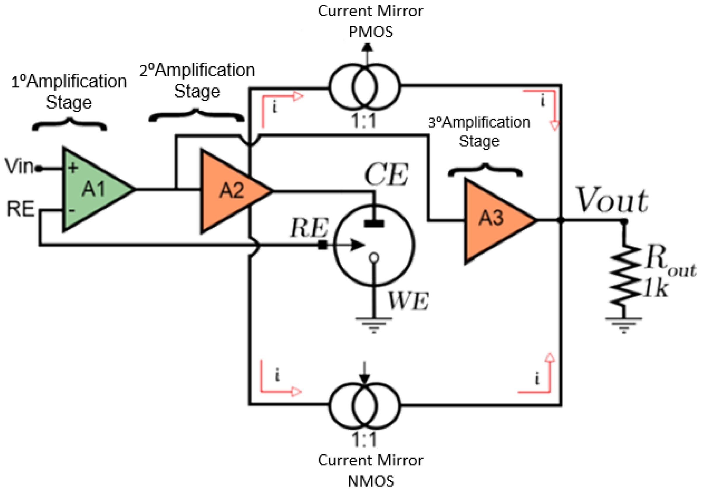
The functional block diagram of the CMIPot circuit is presented in
Figure 2, providing a more detailed understanding of its components. The CMIPot potentiostat consists of three amplifiers, each serving different functionalities, two complementary PMOS and NMOS current mirrors, and a load resistor for reading the output signal. It also includes a dummy model of a three-electrode electrochemical cell.
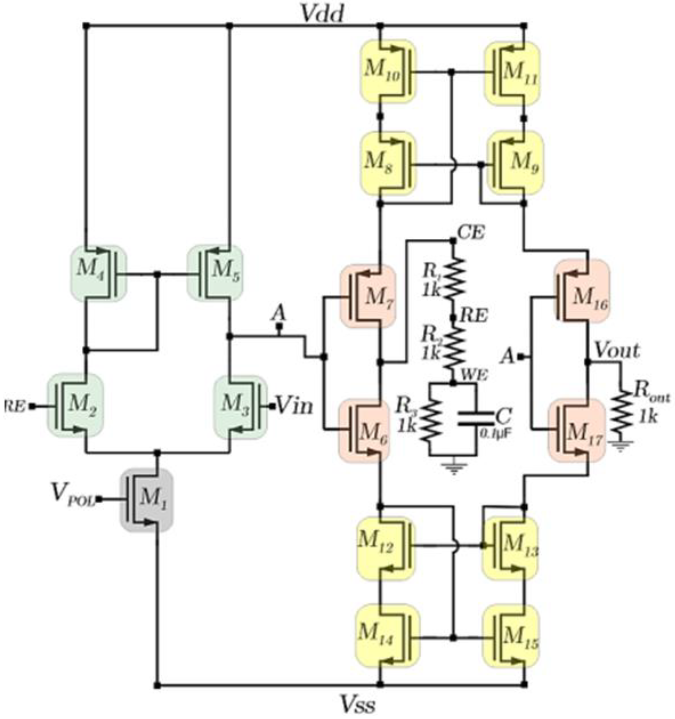
The schematic representation of the CMIPot potentiostat is show in
Figure 3. The schematic employs a potentiostat topology with a novel approach to current measurement, specifically developed for use in electrochemical cells.
To control the potentials across the reference (RE) and working (WE) electrodes, a system with two cascaded amplifiers was devised. The first stage consists of a differential pair with a PMOS active load (M1—M5), while the second stage is a push-pull stage (M6—M7). The differential pair compares the control (Vin) and feedback (RE) signals, amplifying the resulting difference. The amplified signal is then passed to the push-pull stage, for further amplification before being delivered to the electrochemical cell. The amplification process continues until the input voltage (Vin) is approximately equal to the reference voltage (RE). The current measurement of the electrochemical cell is performed by a set of transistors that form the PMOS and NMOS current mirrors within the circuit, in combination with the amplification stage composed of transistors M16, M17 and Rout.
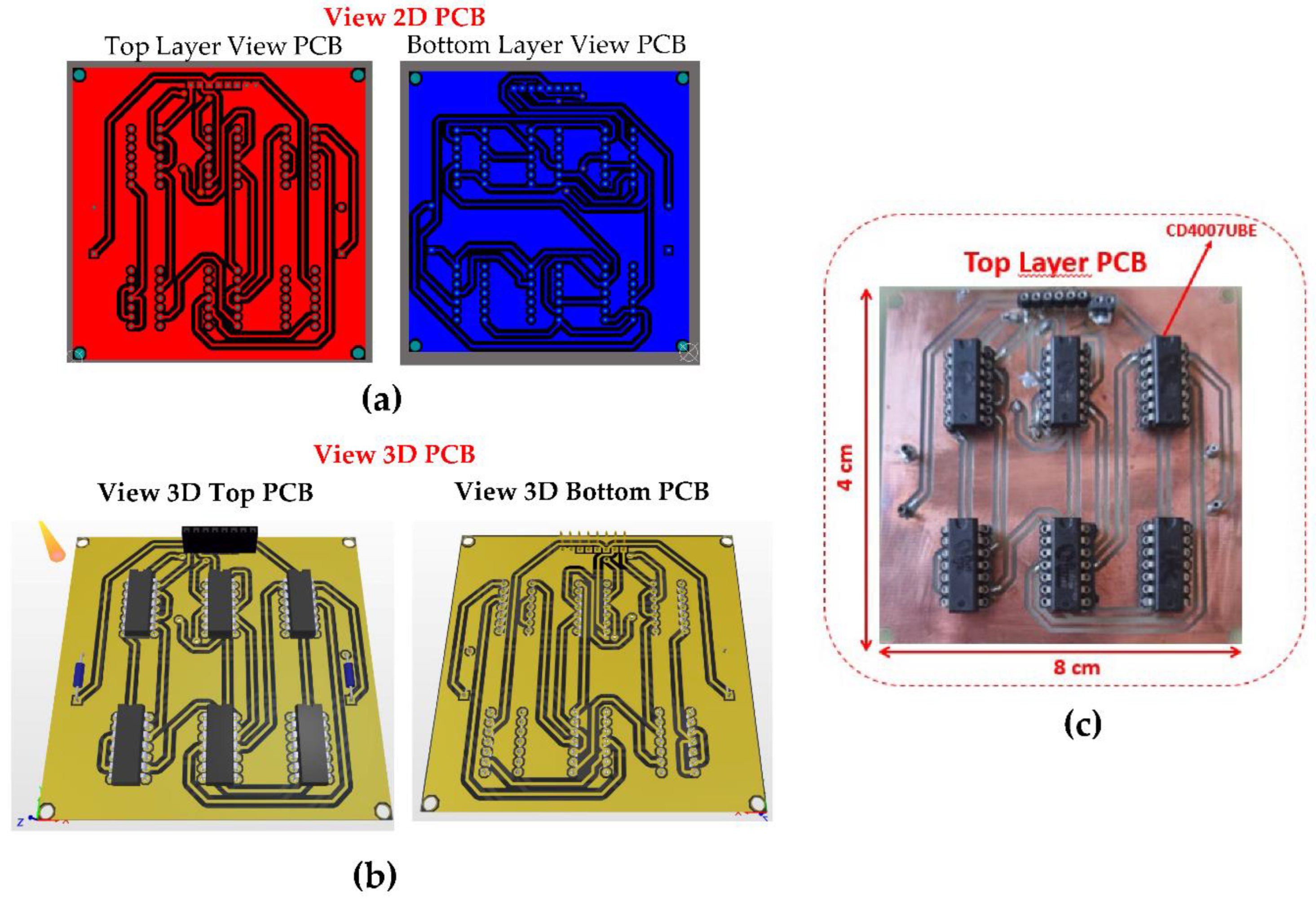
The Printed Circuit Board (PCB) design for the CMIPot was developed according to specific requirements by implementing the connections show in the schematic in
Figure 3, using the CD4007UBE integrated circuit from Texas Instruments as a basis for the physical implementation of the circuit. The
Figure 4a shows the 2D view of the top and bottom layers of the PCB, while
Figure 4b ilustrates the 3D view of the top and bottom layers. These complementary views provide a comprehensive understanding of the layout and placement of components.
Figure 4c displays the fabricated PCB, highlighting the precise positioning of the CD40007 component and the arrangement of the connection traces.
2.2. Reagentes and Chemicals
All solutions were prepared using in ultrapure water obtained from a water purification system (Osmose Smart INOX, VEXER), unless stated otherwise. The supporting electrolyte used in the experiments was potassium chloride (KCI), sourced from Dinâmica Química Contemporânea LTDA (Product ID: P.10.0294.072.01.27, Indaiatuba, SP, BR), and prepared at a concentration of 3M KCl at room temperature. The analyte used in the experiments was potassium ferricyanide, purchased from Lab-Synth (Diadema, SP, Brazil), and dissolved to create solutions with concentrations of 10 mmol/L, 15 mmol/L, and 20 mmol/L. Alumina polishes were obtained for electrode preparation.
2.3. Potassium Ferricyanide Measurements
To validate the CMIPot for electrochemical measurements, three potassium ferricyanide solutions with concentrations of 10 mmol, 15 mmol, and 20 mmol were prepared in a KCl supporting electrolyte solution (pH 7.4) at room temperature. The device’s response was compared to that of a state-of-the-art commercial potentiostat (Autolab PGSTAT302N, Metrohm Autolab, Utrecht, NL) using cyclic voltammetry (CV) with the following parameters: starting and stopping potential of -0.8 V, a potential range of -0.8 V to +0.8 V, a step potential of 2,4 mV, with scan rates of 10 mV/s, 25 mV/s, 100 mV/s, and 250 mV/s. The electrochemical measurements were conducted using a gold (Au) working electrode (Metrohm: ID 6.1241.060,), a silver/silver chloride (Ag/AgCl) reference electrode (Metrohm: ID 6.07726.100, and a platinum (Pt) counter electrode (Metrohm). A Faraday cage was employd during the experiments, and the solutions were maintained at room temperature.
All experiments were conducted using a 50 mL volume of potassium ferricyanide
. This analyte is commonly used in a potentiostat evaluation due to its well documented kinetic properties, which describe a reversible electrochemical behavior. Ferricyanide can be reduced to ferrocyanide is illustrated by Equation (1); with the reverse reaction- oxidation of ferrocyanide to ferricyanide, as depicted in Equation (2).
2.4. Environmental Test and CMIPot and PGSTAT302N
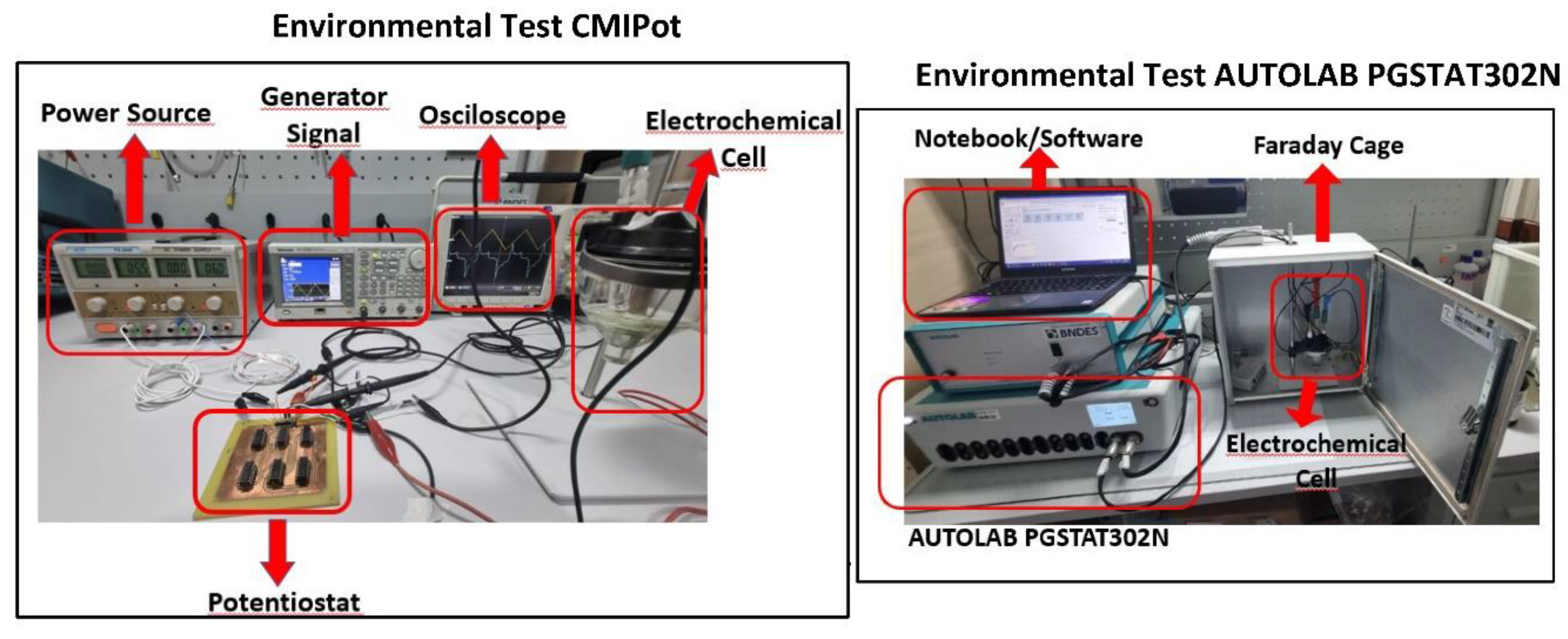
Figure 5 ilustrates the experimental setup for the electrochemical analyses conducted on both potentiostats. The test the proposed CMIPot potentiostat, a DC power supply (ICELL PS-500), a signal generator (Tektronix AFG3252C), a mixed-domain oscilloscope (Tektronix MDO4104B-6), and the three-electrode electrochemical cell with electrodes immersed in a potassium ferricyanide solution were utilized. The testing environment for the AUTOLAB PGSTAT302N commercial potentiostat includes a Faraday cage, the configuration of the three-electrode electrochemical cell with its associated connections, and the INOVA Lab software, which is monitored using a notebook computer.
3. Results and Discussion
This section presents the results of the electrochemical analyses conducted as part of this project. A controlled experimental environment was meticulously designed, as show in
Figure 5, using the CMIPot PCB for a series of tests. The DC source was precisely tuned to a regulated voltage of ±6 V, providing optimal bias for the amplification and current mirror stages of the CMIPot circuit topology. The signal generator was configured for cyclic voltammetry, and the equipment was connected to the three-electrode electrochemical cell. To evaluate the system’s sensitivity, four different scan rates (10 mV/s, 25 mV/s, 100 mV/s, and 250 mV/s) were used with three concentrations (10, 15 and 20mmol/L) of
solution.
A second testing environment was set up for data collection and comparative analysis, utilizing the AUTOLAB PGSTAT302N commercial potentiostat along with the necessary auxiliary equipment, as depicted in
Figure 6. Cyclic voltammetry was applied with the same parameters described previously, allowing for performance comparison between the CMIPot and the commercial reference system.
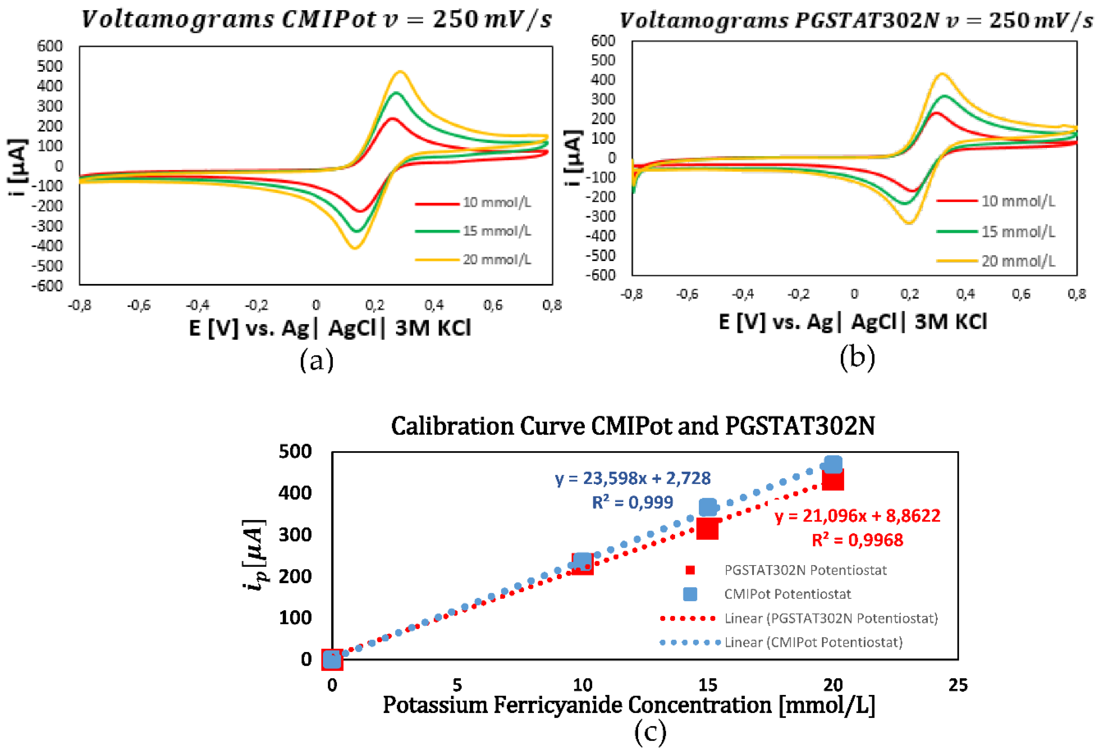
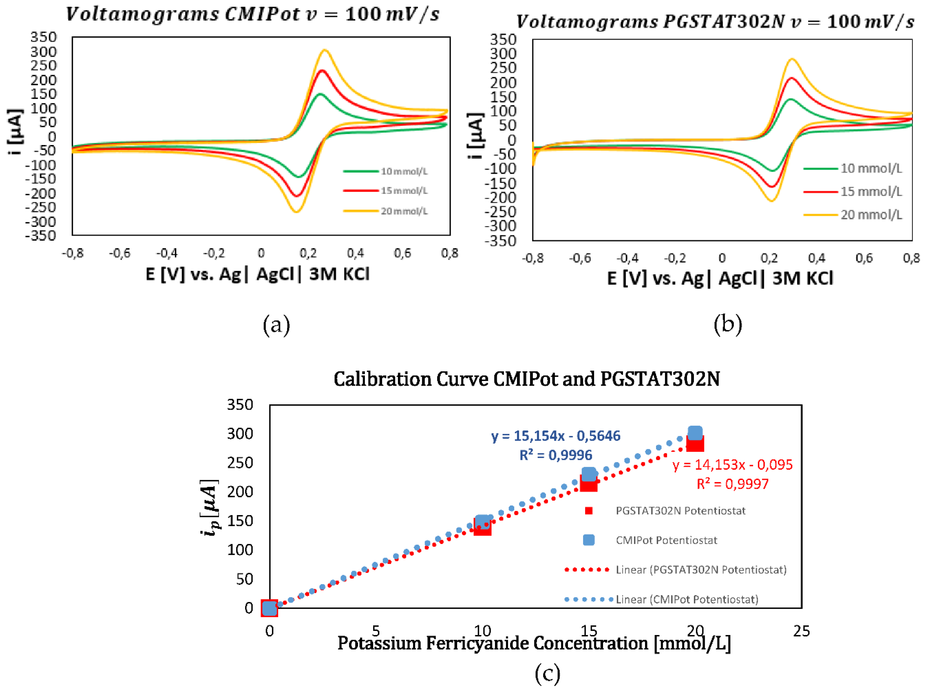
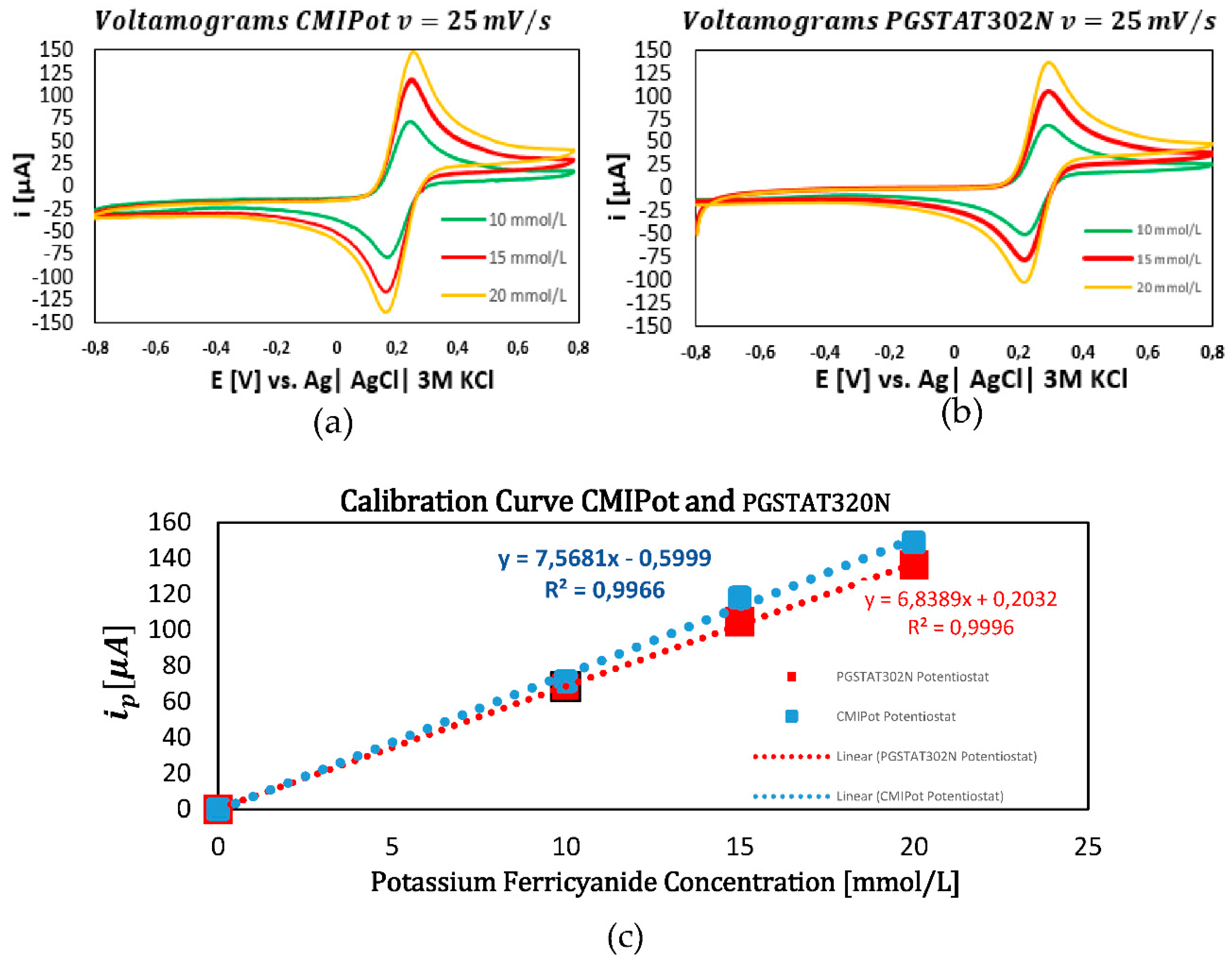
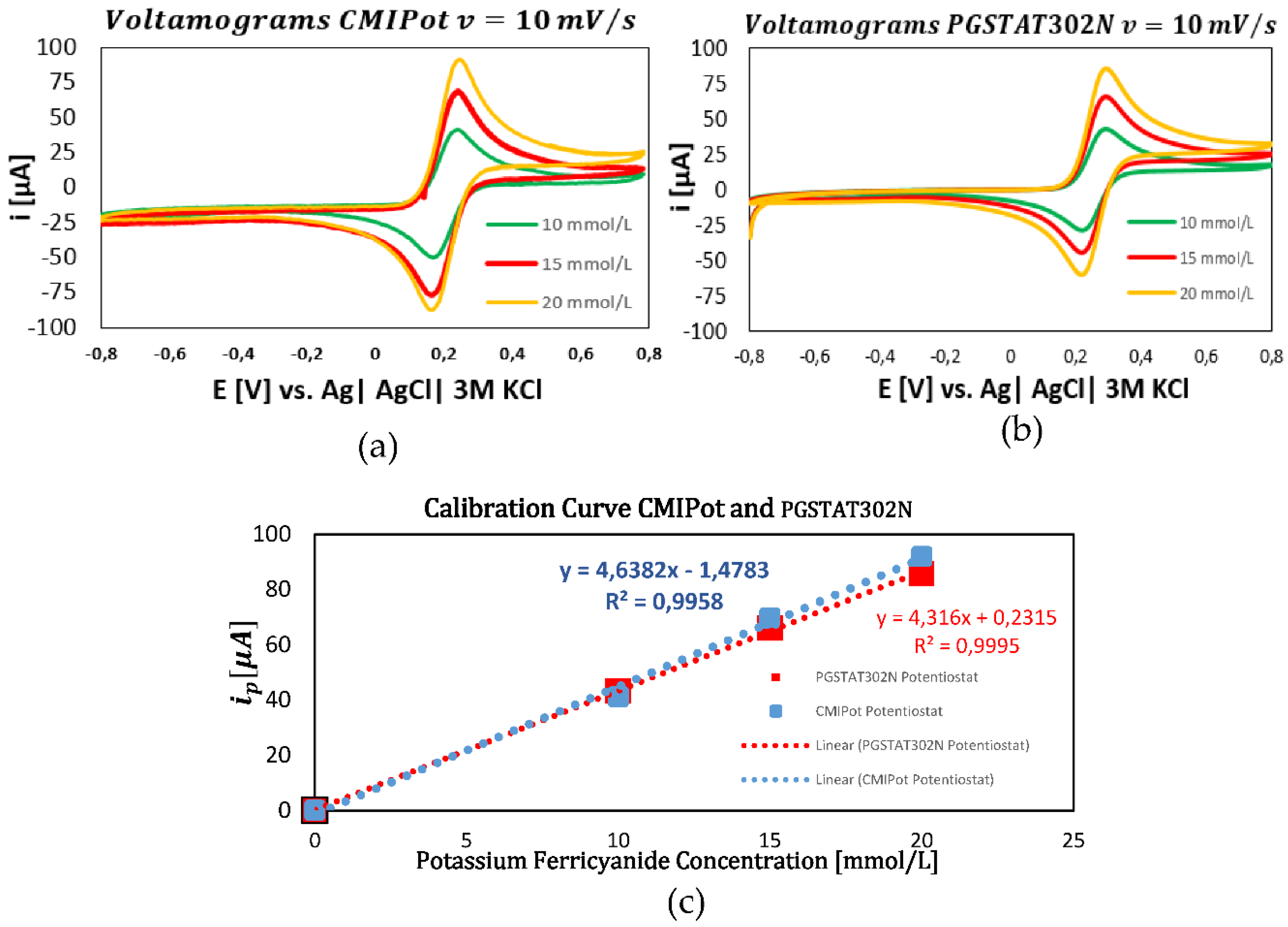
The following graphs show the results of the electrochemical analyses using K₃[Fe(CN)₆] solutions at concentrations of 10, 15, and 20 mmol/L, with potential scans at four distinct speeds: 250 mV/s, 100 mV/s, 25 mV/s, and 10 mV/s. The performance of the CMIPOT and the Autolab PGSTAT302N, was evaluated to provide a detailed comparison under identical experimental conditions.
In the first set of graphs (
Figure 6a–c) applying cyclic voltammetry at a fixed scan rate of 250 mV/s and evaluating of concentrations of 10, 15, and 20 mmol/L of K₃[Fe(CN)₆], revealed a proportional increase in current peaks with concentration. The calibration curves, obtained through linear regression, showed high coefficients of determination 0.999 for the CMIPot and 0.996 for the Autolab PGSTAT302N, indicating a robust linear response to concentration variations. Both devices exhibited similar current peaks and calibration curve slopes, demonstrating equivalent sensitivities.
In the second set of graphs, shown in
Figure 7a–c, cyclic voltammetry was performed with a fixed scan rate of 100 mV/s for the same concentrations of 10, 15, and 20 mmol/L. The resulting cyclic voltammograms, continued to exhibit a proportional increase in current peaks with concentration. The calibration curves for both devices at this scan rate displayed consistent and comparable coefficients of determination, with values of 0.9996 for the CMIPot and 0.9997 for the Autolab PGSTAT302N, confirming the accuracy of the measurements.
In the third set of graphs, presented in
Figure 8a–c, the scan rate was fixed at 25 mV/s. The cyclic voltammograms for concentrations of 10, 15, and 20 mmol/L continued to show a proportional relationship between current peaks and concentration for both potentiostats. The calibration curves exhibited high coefficients of determination, with values of 0.996 for the CMIPot and 0.999 for the Autolab PGSTAT302N.
In the fourth and final set of graphs, displayed in
Figure 9a–c, the scan rate was fixed at 10 mV/s. The analyses of 10, 15, and 20 mmol/L concentrations of K₃(Fe(CN)₆ showed that the CMIPOT and PGSTAT302N potenciostats maintained linearity in the current responses. The calibration curves, obtained through linear regression, exhibited coefficients of determination close to 1, with values of 0.995 for the CMIPot and 0.999 for the Autolab PGSTAT302N.
The comparative analysis of the CMIPOT and Autolab PGSTAT302N potentiostats, based on cyclic voltammetry data with K₃[Fe(CN)₆] solutions at concentrations of 10, 15, and 20 mmol/L, shows that both devices deliver equivalent and reliable performance under the tested conditions. At all tested scan rates (10 mV/s, 25 mV/s, 100 mV/s, and 250 mV/s), both the potentiostats demonstrated robust linear responses, with coefficients of determination near 1, indicating high precision and consistency. Both devices exhibited proportional current peaks relative to K₃[Fe(CN)₆] concentrations and showed comparable calibration curve slopes, signifying equivalent sensitivity. The results across different scan rates confirm the linearity and reproducibility of both devices, highlighting their capability for precise and consistent electrochemical measurements.
4. Conclusion
This study introduces a new compact CMIPot potentiostat circuit designed for electrochemical cells. The circuit functions as a control interface for the voltage polarization on sensor electrodes and for measuring current through the electrochemical cell. The proposed design features a two-stage amplifier, coupled NMOS and PMOS current mirrors, and a push-pull CMOS output stage, effectively capturing the current during oxidation-reduction process in analysis solutions.
The experiments, using the cyclic voltammetry with voltage ranges of ±0.8 V and scan rates of 10 mV/s, 25 mV/s, 100 mV/s, and 250 mV/s, demonstrated that the circuit accurately measures currents from 10 µA to 500 µA with high precision. Validation was achieved with a potassium ferricyanide (K₃[Fe(CN)₆]) redox solution at concentrations of 10, 15, and 20 mmol/L, enabling a detailed analysis of the resulting voltamograms.
The experimental results indicate that the proposed topology performs comparably to classical topologies found in literature and in industrial equipment. The circuit’s precision and consistency validate its effectiveness, showing that the new compact CMOS potentiostat is a viable alternative for electrochemical applications. The study confirms that the circuit delivers reliable and consistent measurements, meeting established technological standards. This lays a strong foundation for future research and advancements in CMOS potentiostats.
Author Contributions
The contributions of the authors of this work are pointed as follows: Conceptualization, A.K.P.S.; methodology, A.K.P.S. and F.B.P. ; validation, A.K.P.S., F.B.P., C.A.d.M.C. and É.C.D.e.S.J. ; formal analysis, A.K.P.S.; investigation, A.K.P.S.; resources, A.K.P.S. and F.B.P.; data curation, A.K.P.S.; writing—original draft preparation, A.K.P.S.; writing—review and editing, A.K.P.S. and C.A.d.M.C.; visualization, A.K.P.S.; supervision, C.A.d.M.C.; project administration, A.K.P.S. and C.A.d.M.C.; funding acquisition, É.C.D.e.S.J. All authors have read and agreed to the published version of the manuscript.
Funding
This work is supported by the Institute of Innovation in Microelectronic-ISI ME. This study was financed in part by the Coordenação de Aperfeiçoamento de Pessoal de Nível Superior - Brasil (CAPES) - Finance Code 001.
Acknowledgments
This work has been supported by the following Brazilian research agencies: FAPEAM, CAPES and CNPq. The authors would like to acknowledge the Graduate Program of Electrical Engineering (PPGEE) of the Universidade Federal do Amazonas, Manaus, Brazil.
References
- Xiao, Z.; Tan, X.; Chen, X.; Chen, S.; Zhang, Z.; Zhang, H.; Wang, J.; Huang, Y.; Zhang, P.; Zheng, L.; Min, H. An Implantable RFID Sensor Tag Toward Continuous Glucose Monitoring. IEEE J. Biomed. Health Inform. 2015, 19, 1281–1288. [Google Scholar] [CrossRef] [PubMed]
- Souza, D.D.; Machado, S.A.S.; Giarola, J.F.; Oliveira, O.N.; Mattoso, L.H.C.; Fonseca, F.J.; Azevedo, S.S. Low-Cost Potentiostats for Electrochemical Applications: Recent Advances. Sensors 2021, 21, 5068. [Google Scholar] [CrossRef]
- Wang, M.; Yang, Y.; Min, J.; Song, Y.; Tu, J.; Mukasa, D.; Ye, C.; Xu, C.; Heflin, N.; McCune, J.S.; Hsiai, T.K.; Li, Z.; Gao, W. A Wearable Electrochemical Biosensor for the Monitoring of Metabolites and Nutrients. Nat. Biomed. Eng. 2022, 6, 1225–1235. [Google Scholar] [CrossRef]
- Ahmadi, M.M.; Jullien, G.A.; Iniewski, K. (Eds.) Circuits for Amperometric Electrochemical Sensors. In VLSI Circuit Design for Biomedical Applications; Artech House: Norwood, MA, 2008; pp. 189–217. [Google Scholar]
- Kim, J.; Kuo, H. A 1.2V Low-Power CMOS Chopper-Stabilized Analog Front-End IC for Glucose Monitoring. IEEE Sensors J. 2016, 16, 3064–3072. [Google Scholar] [CrossRef]
- Khandaker, A.; Mamun, A.; Islam, S.K.; Hensley, D.K.; McFarlane, N. A Glucose Biosensor Using CMOS Potentiostat and Vertically Aligned Carbon Nanofibers. IEEE Trans. Biomed. Circuits Syst. 2016, 10, 817–825. [Google Scholar] [CrossRef]
- Kimura, M.; Fukushima, H.; Sagawa, Y.; Setsu, K.; Hara, H.; Inoue, S. An Integrated Potentiostat With an Electrochemical Cell Using Thin-Film Transistors. IEEE Trans. Electron Devices 2009, 56, 1864–1872. [Google Scholar] [CrossRef]
- Zuo, L.; Islam, S.K.; Mahub, I.; Quaiyum, F. A Low-Power 1-V Potentiostat for Glucose Sensors. IEEE Trans. Circuits Syst. II: Express Briefs 2015, 62, 128–132. [Google Scholar] [CrossRef]
- Ahmadi, M.M.; Jullien, G.A. Current-Mirror-Based Potentiostats for Three-Electrode Amperometric Electrochemical Sensors. IEEE Trans. Circuits Syst. I: Regular Papers 2009, 56, 1493–1502. [Google Scholar] [CrossRef]
- Ding, Y.; Zhang, Y.; Wang, Y.; Su, L. Advances in Sensors for Wound Healing Applications. ACS Appl. Mater. Interfaces 2019, 11, 21820–21831. [Google Scholar]
- Hwang, J.; Seo, J. Electrochemical Sensor for Real-Time Monitoring of Heavy Metals in Water. Sensors 2022, 22, 3711. [Google Scholar] [CrossRef]
- Kim, S.; Lee, H.; Park, S. A Highly Integrated CMOS Potentiostat with Low-Noise Readout Circuitry for Electrochemical Biosensors. IEEE Trans. Biomed. Circuits Syst. 2023, 17, 73–84. [Google Scholar]
- Luo, T.; Wang, H.; Song, H.; Christen, J.B. CMOS Potentiostat for Chemical Sensing Applications. Sensors IEEE 2013. [Google Scholar]
- Liu, X.; Cheng, R.; Tehrani, F.; Bavarian, B. A Review: Electrochemical Biosensors for Cardiac Biomarker Detection. Sensors 2020, 20, 1602. [Google Scholar] [CrossRef]
- Pundir, C.S.; Deswal, R. Biosensors: Recent Advances and Future Challenges. Anal. Bioanal. Chem. 2021, 413, 2311–2331. [Google Scholar]
- Luo, L.; Xu, Y.; Cai, C.; Liu, Q.; Jiang, J. Recent Advances in CMOS Potentiostats for Electrochemical Sensing Applications. Sensors 2022, 22, 1764. [Google Scholar] [CrossRef]
- Qian, Y.; Zhao, X.; Wang, H. Development of a High-Precision CMOS Potentiostat for Environmental Monitoring. IEEE Sensors J. 2021, 21, 24896–24903. [Google Scholar]
- Arduini, F.; Cinti, S.; Scognamiglio, V.; Moscone, D.; Palleschi, G. How Cutting-Edge Technologies Impact the Design of Electrochemical (Bio)sensors for Environmental Analysis. A Review. Anal. Chim. Acta 2018, 989, 1–19. [Google Scholar] [CrossRef]
- Xu, S.; Liu, Y.; Wang, T.; Li, J.; Jin, W. Miniaturized and Integrated Electrochemical Sensors and Systems for Biochemical Detection. Anal. Chem. 2020, 92, 2021–2031. [Google Scholar] [CrossRef]
- Wang, H.; Li, Y.; Wei, J.; Xu, X.; Xu, H. Recent Advances in Portable Electrochemical Sensors for Biomarker Detection. TrAC, Trends Anal. Chem. 2021, 143, 116377. [Google Scholar] [CrossRef]
- Wang, H.; Liang, W. Electrochemical Sensors for Heavy Metal Detection in Water: Recent Progress and Challenges. Chem. Eng. J. 2022, 428, 131207. [Google Scholar] [CrossRef]
- Liu, Y.; Liu, D.; Wei, T.; Chen, X.; Song, H. Portable Electrochemical Sensor for Rapid Detection of Heavy Metals in Environmental Water. J. Electroanal. Chem. 2020, 860, 113875. [Google Scholar]
- Das, P.; Jena, B.K.; Panda, P.K. Recent Advances in Electrochemical Detection of Heavy Metals. In Emerging Trends in Chemical Sciences; Ghosh, S., Ed.; Springer: Singapore, 2021; pp. 147–168. [Google Scholar]
- Kappel, A.; Kellner, K. The Next Generation of Implantable Glucose Sensors: Real-Time Continuous Glucose Monitoring. Chem. Soc. Rev. 2018, 47, 4488–4505. [Google Scholar]
- Yin, M.; Ye, M.; Zhao, Y. Implantable Electrochemical Sensors for Monitoring of Oxygen, Glucose, and Lactate in Tissue Interstitial Fluid. Front. Chem. 2021, 9, 706517. [Google Scholar]
- Zhang, M.; Wang, L.; Li, F.; Tang, D. CMOS Technology for Environmental Monitoring: Recent Progress and Future Prospects. Environ. Sci. Technol. 2023, 57, 1020–1030. [Google Scholar]
- Zhuang, X.; Jiang, W.; Liu, Y.; Wu, Y. Recent Advances in Electrochemical Sensors for the Detection of Heavy Metals in Water. Environ. Sci. Technol. 2021, 55, 3452–3464. [Google Scholar]
- Cioffi, N.; Torsi, L.; Donno, D. Emerging Electrochemical Sensors for Environmental and Clinical Applications. Chem. Rev. 2020, 120, 7080–7118. [Google Scholar]
- Kalluri, J.; Badarinarayan, V.S. Recent Advances in Implantable Glucose Sensors: Materials, Design, and Applications. Biosens. Bioelectron. 2022, 195, 113652. [Google Scholar] [CrossRef]
- Poole, J.L.; Marbach, J. Advances in Implantable Sensors for Blood Glucose Monitoring: A Review. Trends Biotechnol. 2021, 39, 991–1003. [Google Scholar] [CrossRef]
- Khan, M.S.; Hossain, M.L.; Raju, S. Electrochemical Biosensors for Food Safety and Quality Assessment: A Review. J. Agric. Food Chem. 2023, 71, 3937–3950. [Google Scholar]
- Meloni, G.N. Building a Microcontroller-Based Potentiostat: An Inexpensive and Versatile Platform for Teaching Electrochemistry and Instrumentation. J. Chem. Educ. 2016, 93, 1320–1322. [Google Scholar] [CrossRef]
- Li, Y.C.; Melenbrink, E.L.; Cordonier, G.J.; Boggs, C.; Khan, A.; Isaac, M.K.; Nkhonjera, L.K.; Bahati, D.; Billinge, S.J.; Haile, S.M.; Kreuter, R.A.; Crable, R.M.; Mallouk, T.E. An Easily Fabricated Low-Cost Potentiostat Coupled with User-Friendly Software for Introducing Students to Electrochemical Reactions and Electroanalytical Techniques. J. Chem. Educ. 2018, 95, 1658–1661. [Google Scholar] [CrossRef]
- Cordova-Huaman, A.V.; Jauja-Ccana, V.R.; La Rosa-Toro, A. Low-Cost Smartphone-Controlled Potentiostat Based on Arduino for Teaching Electrochemistry Fundamentals and Applications. Heliyon 2021, 7, e06259, URL: https://www.sciencedirect.com/science/article/pii/S2405844021003649. [Google Scholar] [CrossRef] [PubMed]
- Das, A.; Bose, S.; Mandal, N.; Pramanick, B.; RoyChaudhuri, C. HOME-Stat: A Handheld Potentiostat with Open-Access Mobile Interface and Extended Measurement Ranges. Proc. Indian Nat. Sci. Acad. 2021, 87, 84–93. [Google Scholar] [CrossRef]
- Dryden, M.D.M.; Wheeler, A.R. DStat: A Versatile, Open-Source Potentiostat for Electroanalysis and Integration. PLoS ONE 2015, 10, e0140349, URL: https://journals.plos.org/plosone/article?id=10.1371/journal.pone.0140349. [Google Scholar] [CrossRef]
- Jenkins, D.M.; Lee, B.E.; Jun, S.; Reyes-De-Corcuera, J.; McLamore, E.S. ABEstat: A Fully Open-Source and Versatile Wireless Potentiostat Project Including Electrochemical Impedance Spectroscopy. J. Electrochem. Soc. 2019, 166, B3056, URL: https://iopscience.iop.org/article/10.1149/2.0061909jes. [Google Scholar] [CrossRef]
- Anshori, I.; Mufiddin, G.F.; Ramadhan, I.F.; Ariasena, E.; Harimurti, S.; Yunkins, H.; Kurniawan, C. Design of Smartphone-Controlled Low-Cost Potentiostat for Cyclic Voltammetry Analysis Based on ESP32 Microcontroller. Sens. Bio-Sens. Res. 2022, 36, 100490, URL: https://www.sciencedirect.com/science/article/pii/S2214180422000198. [Google Scholar] [CrossRef]
- Irving, P.; Cecil, R.; Yates, M.Z. MYSTAT: A Compact Potentiostat/Galvanostat for General Electrochemistry Measurements. HardwareX 2021, 9, e00163, URL: https://www.sciencedirect.com/science/article/pii/S2468067220300729. [Google Scholar] [CrossRef]
- Brown, E.W.; Glasscott, M.W.; Conley, K.; Barr, J.; Ray, J.D.; Moores, L.C.; Netchaev, A. ACESstat: A DIY Guide to Unlocking the Potential of Integrated Circuit Potentiostats for Open-Source Electrochemical Analysis. Anal. Chem. 2022, 94, 4906–4912. [Google Scholar] [CrossRef]
- Lopin, P.; Lopin, K.V. PSoC-Stat: A Single Chip Open Source Potentiostat Based on a Programmable System on a Chip. PLoS ONE 2018, 13, e0201353, URL: https://journals.plos.org/plosone/article?id=10.1371/journal.pone.0201353. [Google Scholar] [CrossRef]
- Stratmann, L.; Heery, B.; Coffey, B. EmStat Pico: Embedded Electrochemistry with a Miniaturized, Software-Enabled Potentiostat System on Module.
- Hu, J.; Chen, J.; Guo, X.; Zhang, X. Design and Optimization of a CMOS Potentiostat for Electrochemical Sensing Applications. Sensors Actuators B: Chem. 2022, 359, 131579. [Google Scholar] [CrossRef]
- Qiu, X.; Wang, S. Development of Highly Integrated CMOS Electrochemical Sensors for Point-of-Care Diagnostics. Biosens. Bioelectron. 2021, 188, 113338. [Google Scholar] [CrossRef]
|
Disclaimer/Publisher’s Note: The statements, opinions and data contained in all publications are solely those of the individual author(s) and contributor(s) and not of MDPI and/or the editor(s). MDPI and/or the editor(s) disclaim responsibility for any injury to people or property resulting from any ideas, methods, instructions or products referred to in the content. |
© 2024 by the authors. Licensee MDPI, Basel, Switzerland. This article is an open access article distributed under the terms and conditions of the Creative Commons Attribution (CC BY) license (http://creativecommons.org/licenses/by/4.0/).

