1. Introduction
During maritime operations, sometimes USVs are required to perform precise positioning tasks, such as data observation at specific locations, and maintaining the position to operation a ROV, or waiting for retrieval by the mother ship. To meet the control requirements for offshore stationary operations, the most common approach is to utilize a dynamic positioning system. The core methodology of dynamic positioning control lies in equipping the vessel with redundant thrusters and employing appropriate control force and torque distribution techniques to achieve omnidirectional control over the three degrees of freedom on the water in overdriven conditions [
1,
2,
3].
For large yachts equipped with thruster groups, Ref. [
4] designed a sampled-data controller specifically tailored for cruise ships utilizing dynamic positioning systems, thereby improving their positioning stability. Nevertheless, due to the underpowered propulsion systems of most smaller vessels, controlling their direction becomes challenging, rendering the overall control problem considerably more complex. Ref. [
5] tackles the station-keeping challenge for small autonomous surface vehicles (ASVs) subject to significant wind drag by incorporating wind feedforward, maintaining the positional error within approximately the length of one vehicle. Taking into account the limitations of wave gliders, which include slow speed and limited maneuverability, Ref. [
6] introduces an innovative adaptive station-keeping tactic that integrates optimal positioning control with adaptive dead zone management. This approach permits the flexible adjustment of the dead zone radius to counteract variable environmental disturbances.
Various researchers have employed different control strategies to counteract the effects of multi-source disturbances on the dynamic positioning control of small unmanned surface vehicles (USVs) [
7,
8,
9,
10]. In Ref. [
11], a study compares the performance of nonlinear proportional-derivative, backstepping, and sliding mode feedback controllers in windy conditions, both with and without wind feedforward control. This comparison was conducted using a 4-meter long, 180-kilogram USV in winds ranging from 4-5 knots. To tackle wave-induced disturbances in dynamic positioning, Ref. [
12] presents a control scheme based on the Kalman filter, designed for dynamic positioning stability in the presence of wave disturbances and shallow water conditions. Ref. [
13] suggests a cascaded proportional-derivative feedforward control approach to mitigate disturbances, where disturbance estimates are used to compensate for state perturbations.
Several studies have focused on optimizing the dynamic positioning stability and control performance of small unmanned surface vessels [
14,
15,
16]. In Ref. [
17], the integration of adaptive control and backstepping techniques enhances the rapid transient response and robustness of USVs operating in shallow waters during dynamic positioning. Ref. [
18] introduces a robust adaptive control scheme derived from the tan-type barrier Lyapunov function, thereby guaranteeing that the position and velocity of dynamically positioned vessels stay within predefined constraints.
To strike a balance between maintaining the heading of unmanned boats during positioning tasks, Ref. [
19] addresses the challenge of simultaneously considering positional and heading angle constraints in the underactuated state of USVs. It proposes a station-keeping control strategy based on heading constraints specifically designed to enhance the lateral positioning accuracy of the USVs. In an effort to further augment the attitude stabilization capabilities, Ref. [
20] introduces a station-keeping control method tailored for underactuated USVs. This approach incorporates the nonlinear separation principle and implements a gradually adapting law to adjust the USV's heading, effectively countering environmental disturbances of unknown size and direction.
The proposed schemes rely on nonlinear modeling of USVs, inevitably compromising real-time control responsiveness. Therefore, it's crucial to strike a balance between system complexity and performance. Due to their smaller size and budgetary constraints, small to medium-sized USVs typically lack redundant propellers, hence they don't possess dynamic positioning capabilities. For these conventionally underactuated boats, how to achieving high-precision, energy-efficient fixed-point control through sustained power output remains a challenge. This challenge mimics physical anchoring and holds significant practical relevance and complexity. However, limited research exists on virtual anchoring methods for small USVs, driving the need for the study presented in this paper.
In this paper, based on the previous experiences in conducting unmanned boat control tests at sea, we propose a control method that effectively simulates anchoring at a fixed point, named ‘virtual anchor’ control technology.This innovative approach enables the USV to automatically discern the direction of the current, even without prior knowledge of its velocity or direction. By orienting its bow to face the oncoming current, the boat adjusts its longitudinal thrust to maintain a stationary position relative to the ground. Additionally, it provides a precise real-time estimation of the current direction angle. This method is comprised by four steps. Firstly, a linear concise motion model with unknown disturbances is proposed. Then, the motion planning law is designed by imitating underlying principles of ship anchoring. Next, an adaptive disturbance observer is proposed for estimating uncertainties in the motion model. Last step, based on the observer, a sliding-mode method is used for heading control law designing, and thrust control law is also conducted by applying the Lyapunov method.
Ultimately, we conducted two motion control simulation experiments. The results indicate that the control system performs robustly, even under significant disturbances and tidal current variations, which demonstrating the strong robustness of the designed controller.
2. Motion Modeling of Unmanned Surface Vehicle in Slow-Varying Currents
In environments with relatively stable ocean currents and tidal flows, where the velocity and direction of the flow undergo minimal changes over short timescales, the immediate surroundings of an unmanned surface vehicle (USV) can be reasonably approximated as a steady current. When modeling the motion of ships in the presence of currents, there are primarily two established methodologies based on the MMG (ship Manoeuvring Model Group) separated-type maneuvering model: force superposition and velocity superposition. One approach incorporates the effect of water currents as an additive force on the vessel hull, as exemplified in studies by Faltinson, LIU, and others [
21,
22]. Alternatively, another method employs a relative velocity superposition, considering the vessel's ground speed as a vector sum of its speed relative to the water and the current velocity. This approach is exemplified by works from Fossen, Do K D, and their colleagues [
23,
24].
From a theoretical standpoint, the force superposition method exhibits superior accuracy in calculations. Nevertheless, it necessitates precise determinations of hull resistance coefficients under various current directions and encounter angles, often requiring ship model basin tests. While this method proves suitable for larger vessels and offshore platforms, it poses challenges for small USVs. This is primarily due to the fact that small USVs rarely undergo additional hydrodynamic testing, rendering the precise acquisition of hull resistance coefficients and added mass coefficients difficult. However, at lower speeds (below 4 knots), the hydrodynamic nonlinear effects of the hull are less significant, facilitating the application of the velocity superposition modeling approach. For single-propeller USVs with a steerable thrust, neglecting the influences of wind and waves on the hull, as well as disregarding nonlinear model coefficients at low speeds, the kinetics and dynamics model for low-speed navigation with three degrees of freedom on the water surface can be formulated as follows:
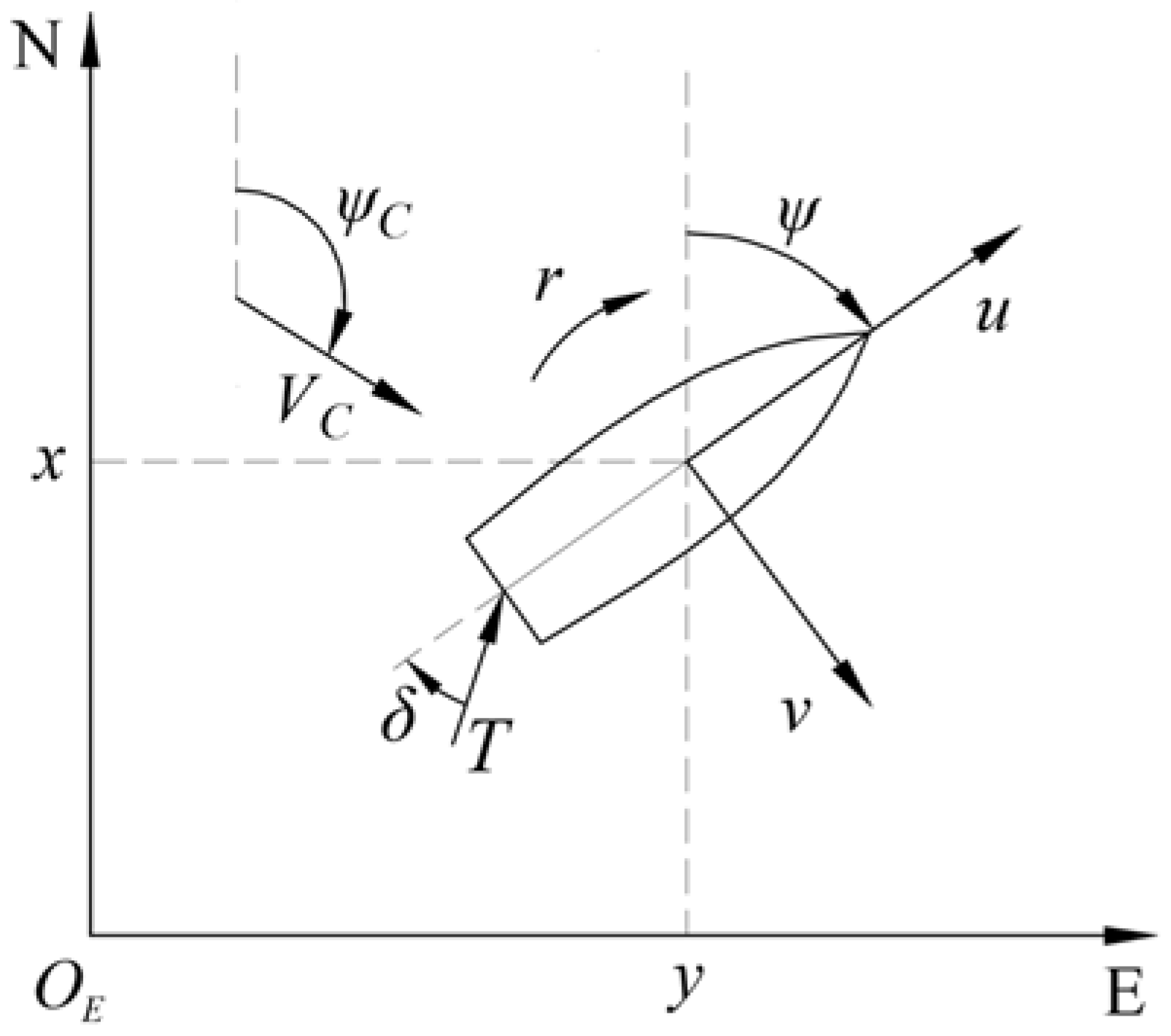
where, (
x,
y) signifies the horizontal location of the USV in the North-East-Down (NED) reference frame, with
ψ representing the hull's heading angle. The variables (
u,
v) depict the longitudinal and lateral velocities relative to the water, respectively, while
r denotes the angular velocity of the hull's yaw.
VC and
ψC stand for the current's flow velocity and direction angle, respectively. The thrust force of the propeller is denoted by
T, the hull length by
L, and the rudder angle by
δ. The inertial masses in the three degrees of freedom (surge, sway, and yaw) are represented by
m11,
m22, and
m33, while
du,
dv, and
dr denote the damping coefficients in the corresponding directions.
However, in practical control applications, the motion parameters and thrust magnitude of small unmanned boats cannot be accurately known. In order to solve this problem, the model of Eq. (2) is rewritten as follows:
In Eq. (3), a1~a3 and b1~b3 are all positive constants, representing the damping coefficients and control force coefficients in the three degrees of freedom respectively. Based on experience, for small unmanned boats, it can be simply assumed that their values are a1~a3 = 1, b1=b2=0.01, b3=0.001. n represents the propeller speed. w1~w3 represent the uncertain disturbance resultant forces in each degrees of freedom.
Given the slow-varying current environment, certain approximations (
≈ 0,
≈ 0) are adopted.
Figure 1 illustrates the 3-DOF motion model on water surface.
For controller design purposes, the kinematics in Eq. (1) are transformed into a polar coordinate system representation, as follows:
Here, (xd, yd) designates the position of the virtual anchor point, and d represents the Euler distance between the USV’s center of gravity and the anchor point. The anchor angle θ, given by atan2(y-yd, x-xd), represents the USV’s north-oriented azimuth relative to the anchor point, serving as a real-time estimate of the unknown current flow direction angle ψC.
In practical applications, satellite navigation systems provide the vessel's ground velocity
uG. Based on this, the relationship between the USV's ground velocity, relative velocity of water, and current velocitiy is derived from Eq. (1):
3. Design of Adaptive Controller for Virtual Anchor Using Back-Stepping Method
3.1. Design of Motion Planning Law
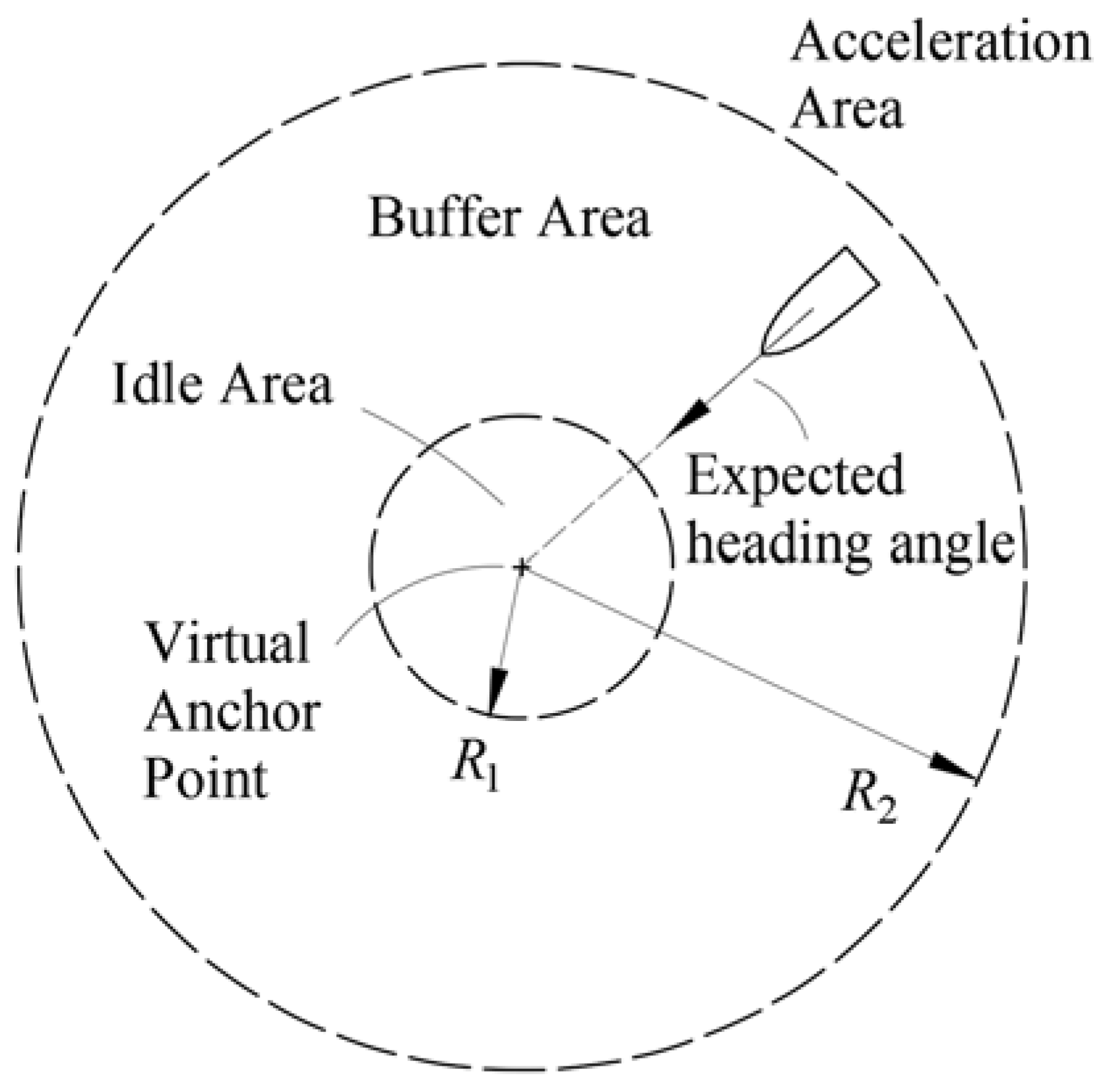
With an arbitrarily designated virtual anchoring point serving as the center, three distinct zones are established based on radii
R1 and
R2: the idle area(
r <
R1), the buffer area(
R1<
r <
R2), and the acceleration area(
r >
R2), as depicted in
Figure 2. In this paper, the virtual anchoring point represents the anchor's position, and
R1 signifies the virtual length of the anchor line. The intended behavior of the USV is to maintain its bow constantly pointed towards the anchoring center, positioned directly downstream, and adjust its thrust to keep a constant distance of
R1 from the anchoring center.
For underactuated USVs, motion planning primarily consists of velocity and heading planning. Concerning heading planning, the objective is to ensure that the USV’s bow consistently faces the intended anchoring point. Therefore, the desired heading
ψd of the USV is formulated as follows:
In terms of velocity planning, the aim is to maintain a constant distance of R1 between the USV and the anchoring point. To achieve this, the desired ground velocity ud of the USV is calculated using the following equation:
In this equation,
uFP denotes the fixed-point speed, which can be manually preset (the default value chosen in this study is 3m/s).
We first define the virtual anchor angle error
and devise a Lyapunov function
. By differentiating both sides and substituting Eq. (3) and Eq. (5), than we can get the follow equation:
For small USVs, especially during low-speed or straight-line navigation, the control input for lateral motion is minimal and can be disregarded. Relying on the passive stability theory [
25], we can safely neglect the lateral drift velocity during virtual anchoring, assuming v = 0. Furthermore, assuming precise heading angle control, where
, Eq. (8) can be reformulated as:
From equation (9), it’s apparent that, given the condition of ,the angle error demonstrates approximately exponential convergence. This convergence of will be achieved within a finite time frame, indicating that the vessel’s bow will automatically align precisely into the oncoming flow.
The anchoring distance error is defined as
, and a Lyapunov function
is designed to analyze the system's stability. By deriving both sides of the equations and incorporating the prior convergence conditions from Eq. (3), (4), and
, we arrive at Eq. (10).
Subsequently, by setting
and substituting Eq. (6) into Eq. (10), we obtain Eq. (11).
Based on Eq. (11), it is evident that the error meets the criteria for exponential convergence. Consequently, the unmanned vessel initially achieves convergence in the bow angle for automated head-on flow, followed by the desired anchoring distance, ultimately attaining the intended positioning control performance.
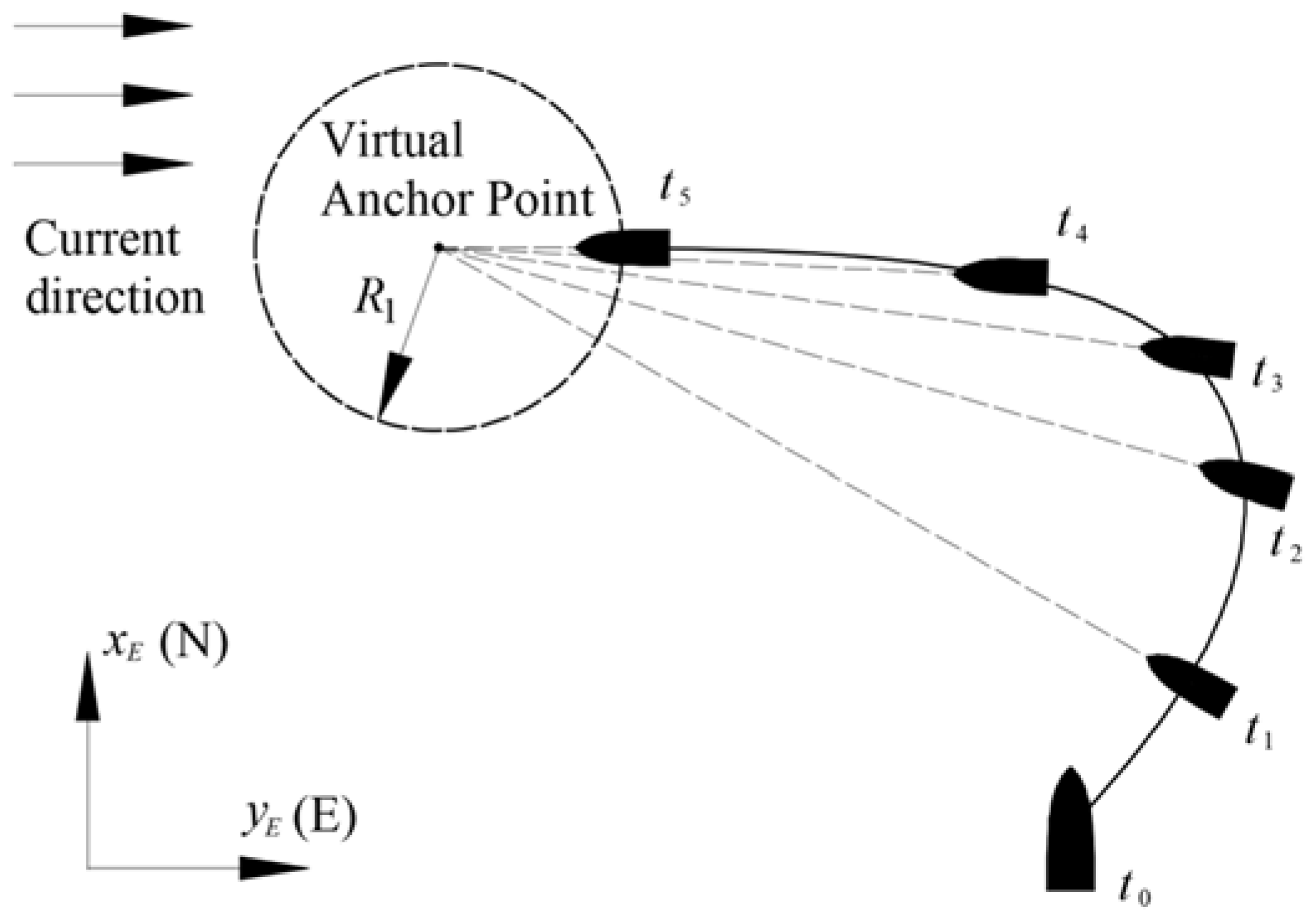
Under the guidance of the aforementioned control law, the USV’s bow consistently points towards the anchoring point and progressively approaches the junction between the idle area and the buffer area. When subjected to steady or gradually varying currents, the USV will stabilize with its bow facing upstream, maintaining a constant distance of R1 from the anchoring point. This not only ensures continuous fixed-point control but also facilitates automatic adjustment of the angle facing the current, thus achieving energy efficiency. The process of virtual anchoring for the USV, along with the ideal trajectory under optimal conditions, is depicted in
Figure 3:
3.2. Design of Adaptive Disturbance Observer
To facilitate the design of subsequent controllers, an adaptive observer is designed to estimate system disturbances for the motion model with unknown disturbance terms. The observer is designed as follows:
where
and
represent the estimated values of the corresponding disturbances, and the initial value of the observer can be set to 0.
k1 represents the disturbance observation gain, which are positive constants and need to be appropriately selected.
To demonstrate the effectiveness of the designed disturbance observer in estimating disturbances, the stability of the observer is proved below. Firstly, we define the estimation error for disturbances in each degree of freedom of the system as follows:
Next, we design the Lyapunov function
. Differentiate both sides of it and substituting equation (3) into it, then we can obtain:
Since the disturbance
w1 are bounded and there must exist a maximum value, assuming it satisfy the condition
. Then, the above equation can be rewritten as:
where
represents an arbitrarily small constant. According to relevant mathematical theorems, it can be inferred that:
Eq. (15) indicates that the disturbance estimation error is globally exponentially stable, and its convergence speed is directly proportional to the value of k1. Additionally, it will converge to a neighborhood within a finite time and remain within that range indefinitely. Since is determined and bounded, while is an arbitrarily small constant, by increasing the disturbance estimation gain k1, the bounds of the neighborhood can be continuously reduced. This allows the estimated values to accurately reflect the actual changes in the system's total uncertainty variable . Similarly, through mathematical derivations from equations (10) to (13), it can be proven that the disturbance observation error is also globally exponentially stable, meaning that the actual values of the corresponding disturbances can also be accurately estimated by .
3.3. Design of Robust Control Law for Rudder and Thrust
In this paper, a sliding mode control algorithm based on disturbance observer is used for the control law of the heading angle.
Firstly, the sliding mode variable S is designed as follows:
where
λ is a positive constant. Defining the Lyapunov function
and taking the derivative of both sides, then we obtain:
Letting the rudder angle
δ control law satisfy the following relationship:
where the boundary function
satisfies the following conditions:
In the above equation, the control coefficients
k2 and
k3 are both positive constants. Substituting equation (19) into equation (18), we can obtain:
Thus, the sliding mode variable S satisfies the condition of asymptotic convergence. According to sliding mode theory, the error between the heading angle and the desired heading angle is also asymptotically convergent.
We define the ground speed error as
, and design the Lyapunov function
. By taking the derivative of both sides, we can obtain:
Since the heading angle error is convergent, thus substituting the assumption condition of
into the above equation yields:
According to Eq. (23), the propeller speed
n is designed as follows:
As the current velocity
VC is unknown, to achieve adaptive adjustment for the unknown current velocity, we proposed a distance error integral function
f(
d) as follows:
In the above equation, an integral contribution gain regulator has been introduced, which replaces the direct integration of (d - R1). Herein, k5 represents a positive constant that serves as the gain weight for the regulator. The advantage of this gain regulator is its ability to automatically adjust the cumulative weight of the integral. Specifically, when the initial distance is excessively large, it reduces the cumulative weight; conversely, when the distance is shorter, the integral weight is automatically amplified.
By accumulating errors through the integral term, the thrust value can be automatically adjusted even without knowledge of the current velocity, achieving a state of equilibrium between thrust and the current. Thus achieving an approximate relationship of .Additionally, the integral gain regulator mitigates system oscillations resulting from significant initial errors, while simultaneously improving the control law’s responsiveness to small deviations. When it comes to selecting gain weights for vessels with a length under 10 meters, a recommended value of is advisable.
Substituting Eq. (24) into Eq. (23), we can obtain:
Since both eu and are bounded, similarly to the prove process from Eq. (14) to (16), it is easy to prove that eu also satisfies the condition of semi-exponential convergence and will converge to a smaller interval.
Based on the backstepping theory, and the proof processes outlined in
Section 3.1,
Section 3.2,
Section 3.3 it can be evaluated that the designed overall control system is stable. Taking into account the necessity for smooth system operation across diverse scenarios in practical applications, we introduce several constraints. For example, we limit the vessel's desired velocity to prevent excessively high speeds during long-distance operations. Furthermore, we ensure the desired speed remains non-negative to avoid reverse thrust issues when the vessel approaches within
d <
R1 of a designated point. Additionally, precautions are taken to avert heading singularities that may arise when the vessel is in close proximity to the anchoring point (specifically, when d <
R1). Building upon the planning principles outlined in Eq. (6) and (7) earlier, we have refined the designs for the unmanned vessel's desired ground speed
ud,, target heading
ψd as below:
Based on previous hull maneuverability testing experience and with the aim of minimizing positioning errors, the idle area and buffer area radii are set to 2 and 5 times the length of the ship, respectively.
As the USV progressively moves into an upstream direction, its heading remains stable. Under the influence of the heading control law, the rudder angle approaches 0, and thrust control becomes solely dependent on speed and distance. Consequently, utilizing an approximate PID control strategy, the unmanned vessel attains convergence of its system state . Specifically, it reaches a predetermined downstream point from the intended anchoring location and maintains its position there, facing upstream.
4. Motion Control Simulation Experiments
To verify the effectiveness of the control method proposed in this paper, three sets of simulation experiments, with and without disturbances and in tidal current, were conducted based on the Simulink software, with a simulation step size of 0.05s. The parameters of the ship motion model used in the simulation are as follows:
m11=2.4×10
3kg,
m22=3.3×10
3kg,
m33=2.49×10
5kg·m
2,
du=255kg/s,
dv=2.92×10
3kg/s,
dr=1.22×10
4kg·m
2/s [
26]. The ship is equipped with a steerable thruster, with a rudder angle range of ±30° and a rudder angle turning rate limited to 10°/s. In each simulations, the relevant control parameters were set as follows:
uFP=3m/s,
k1=,
k2=,
k3=,
k4=,
k5=,
λ=0.2,
R1=15,
R2=30.
4.1. Simulation with Multiple Disturbances
In this simulation, the coordinates of the desired anchoring point (xd, yd) were set to (0,0). The constant current velocity (VC) was set to 1m/s, with a flow direction (ψC) of 45°. The unmanned vessel's initial position (x, y) was (10,0), while all other states (ψ,u,v,r) were initially set to 0.
To simulate motion control in a realistic marine environment, various disturbances were incorporated into the simulations. We first designed the following ocean current disturbance model:
In Eq. (29), the random disturbance terms, and , are both modeled as zero-mean Gaussian white noise, with noise power spectral densities of 0.2 and 0.05, respectively.
Furthermore, to simulate real-world applications on an actual vessel more closely, a 2° rudder angle dead zone was incorporated. The rudder steering model is formulated as follows:
In this equation,
denotes the real-time desired rudder angle computed by the control algorithm, whereas
represents the actual mechanical rudder angle executed by the vessel. The system’s operational status and results during the time range from 0 to 800 seconds are presented in
Figure 4,
Figure 5,
Figure 6,
Figure 7,
Figure 8 and
Figure 9.
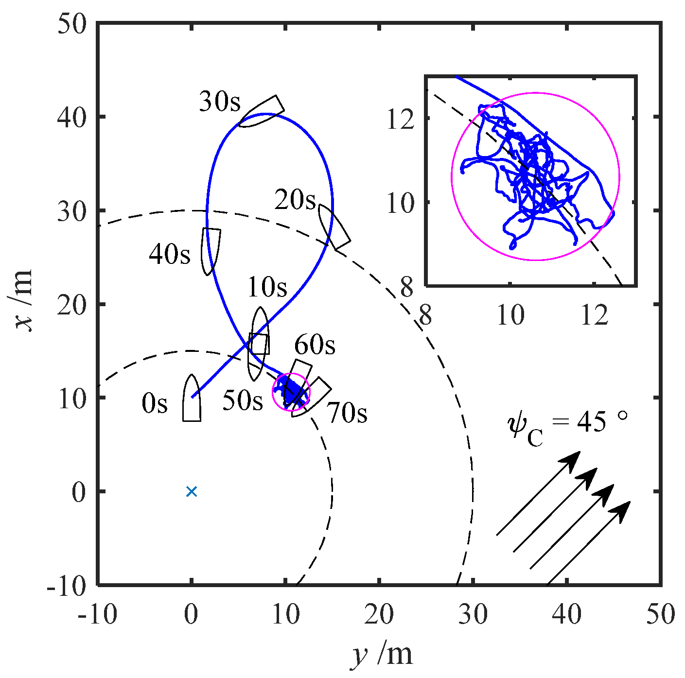
Figure 4 illustrates the historical movement trajectory of the unmanned vessel's center position. To facilitate observation of the movement process, the vessel's positions and heading angles at every 10 seconds from 0 to 70 seconds are plotted on the graph. There are slight variations in the USV’s position from 100s to 800s due to significant disturbances caused by ocean currents. Once the ship's movement stabilizes, it fluctuates within a circular region of radius 2m centered at coordinates (10.6m, 10.6m).
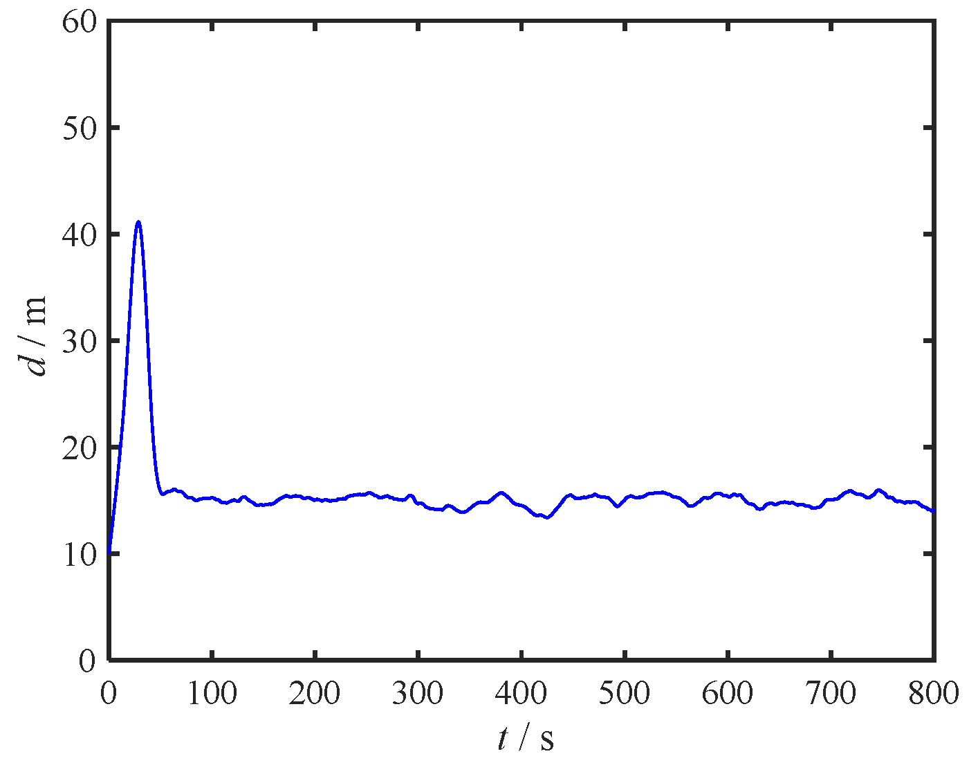
Figure 5 depicts the distance between the center of the unmanned vessel and the desired anchoring point.
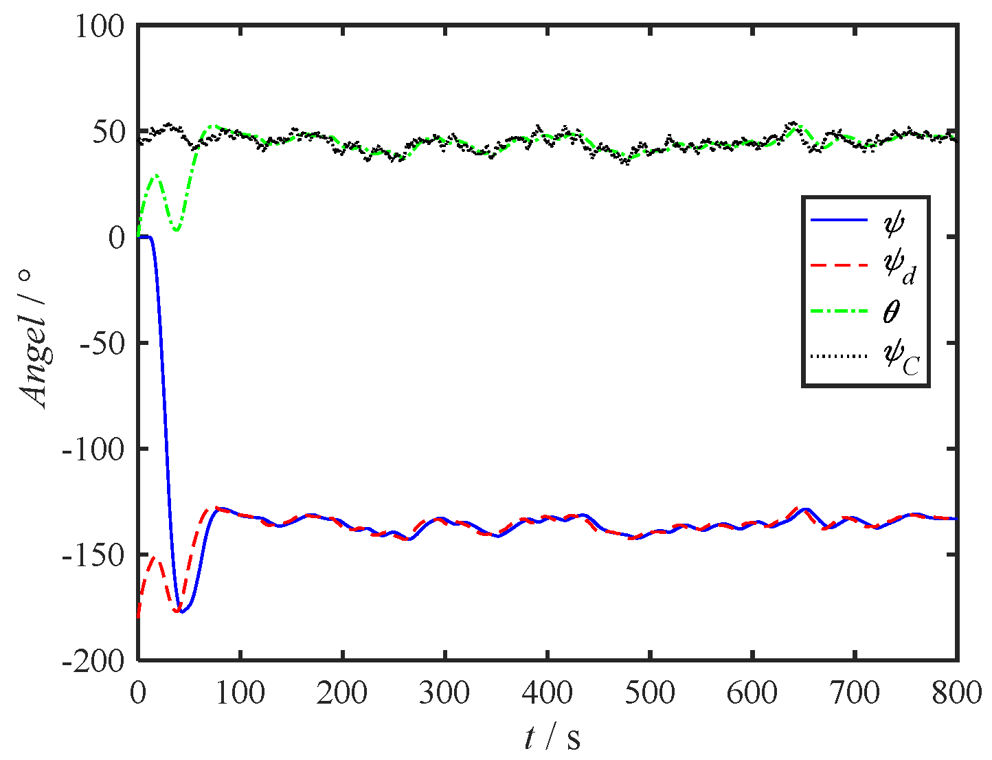
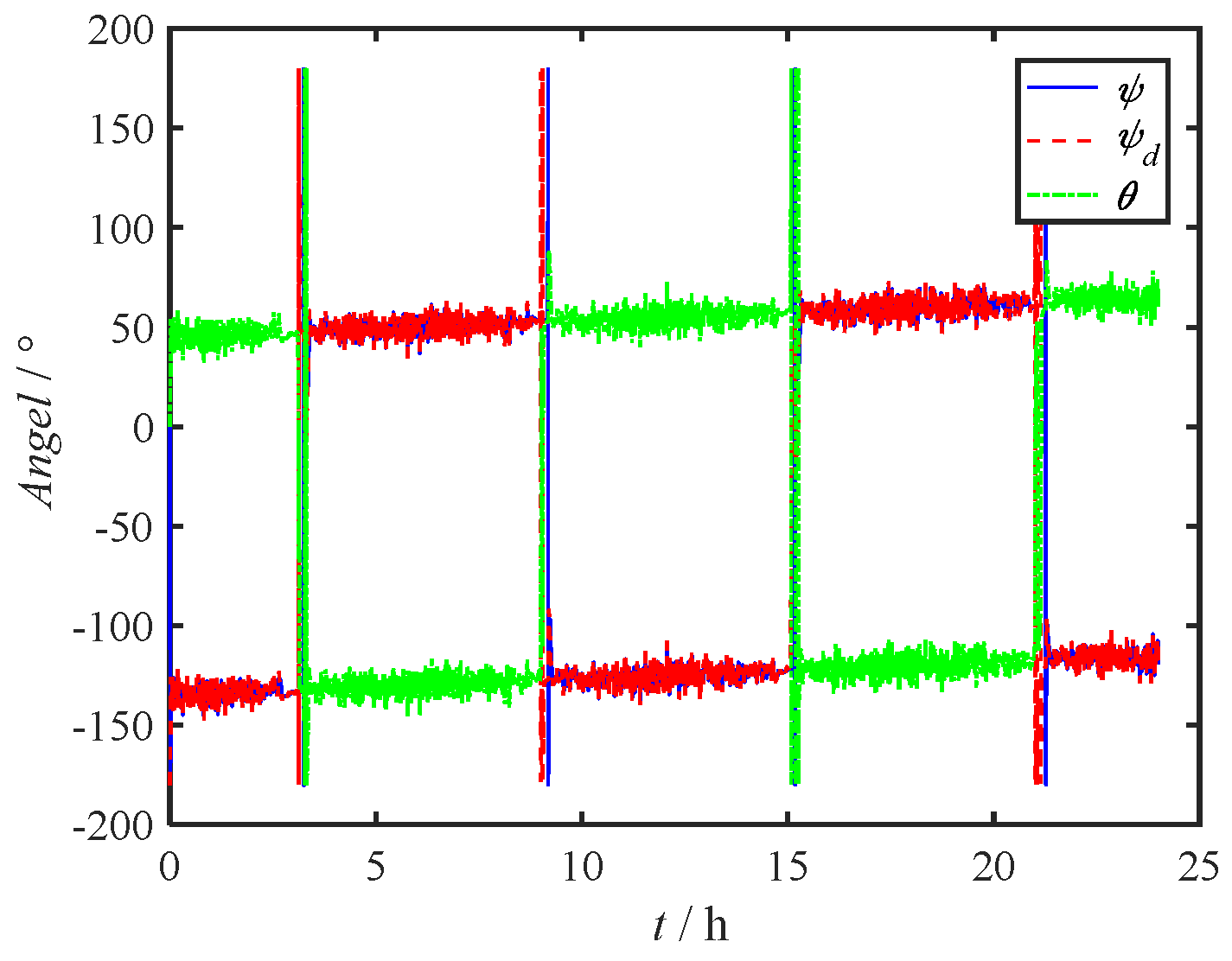
Figure 6 presents time curves for the USV's heading angle, desired heading angle, anchoring angle, and current angle. Evidently, the anchoring angle aligns with the current angle.
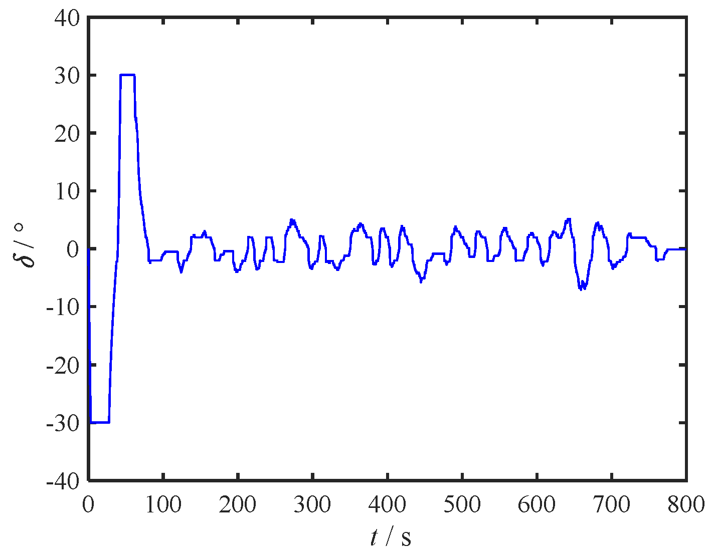
Figure 7 showcases the rudder angle time curve of the unmanned vessel.
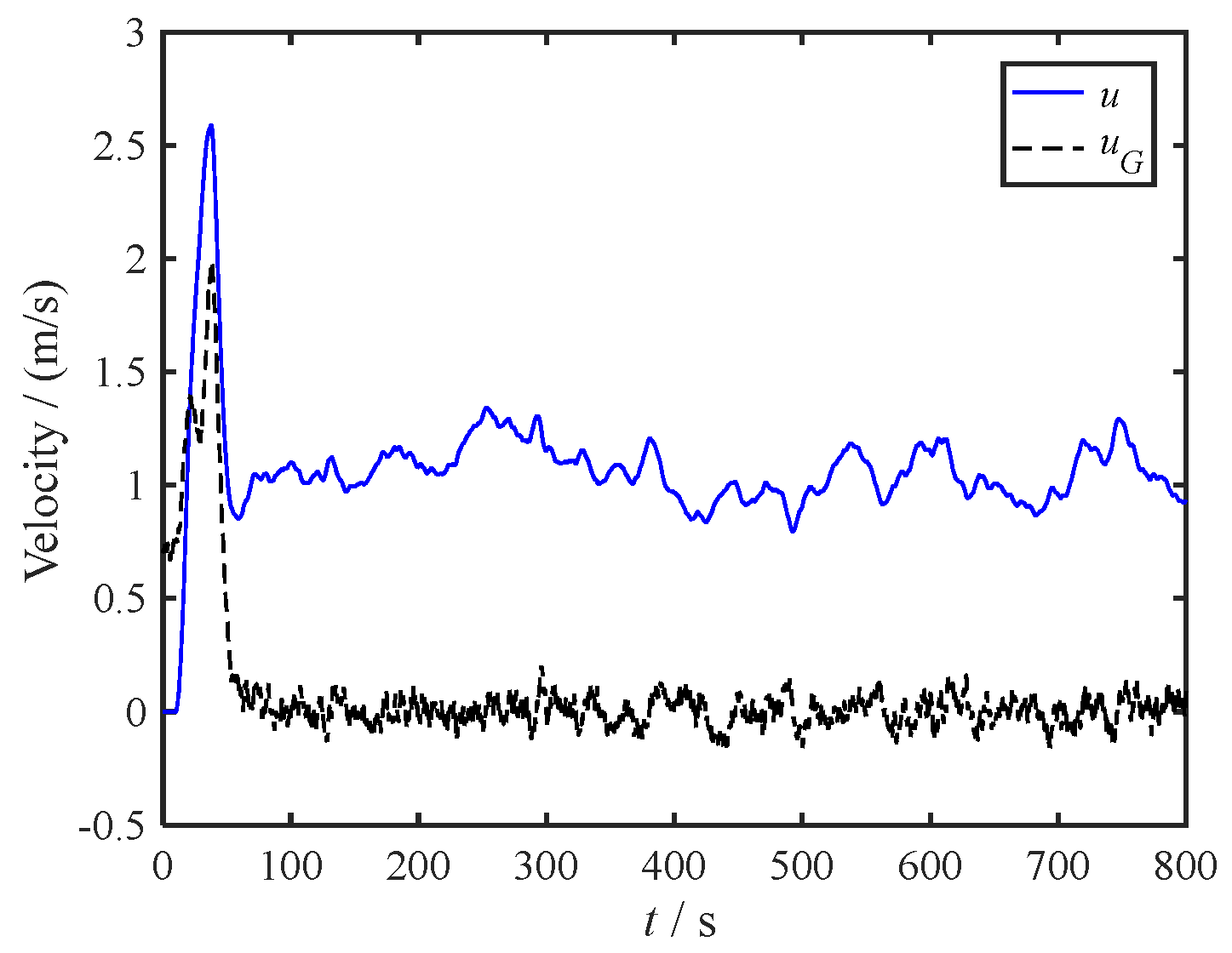
Figure 8 displays the vessel's speed-time curve, encompassing both relative velocity to water (
u) and ground speed (
uG). Lastly,
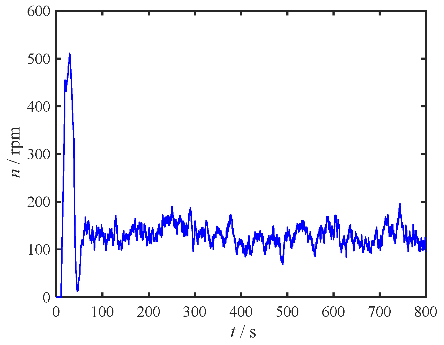
Figure 9 portrays the propeller speed-time curve, indicating that the thrust maintains a steady value once the system stabilizes.
From
Figure 6, it is apparent that after the motion stabilizes, there is a notable estimation accuracy for the real-time changing current direction angle
, denoted as
θ. Within the timeframe of 100s to 800s, the root mean square error (RMS) between the estimated and actual values is 2.45°, adequate for meeting the accuracy standards required for estimating low-frequency flow direction shifts in engineering applications.
The variations in rudder angle depicted in
Figure 7 exhibit a distinct stepped pattern, which is attributable to the mechanical dead zone limitation of 2°. This stepped variation impacts the precision of closed-loop feedback to some extent.
Based on the comprehensive simulation results, it is evident that despite adverse factors like fluctuating current velocity, directional disturbances, and the rudder angle dead zone, the designed control system maintains impressive control performance. Thus, Simulation 1 serves as further confirmation of the robust nature of the proposed control methodology.
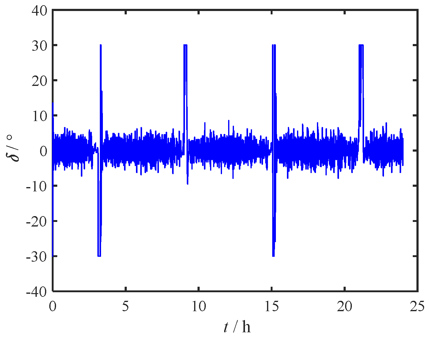
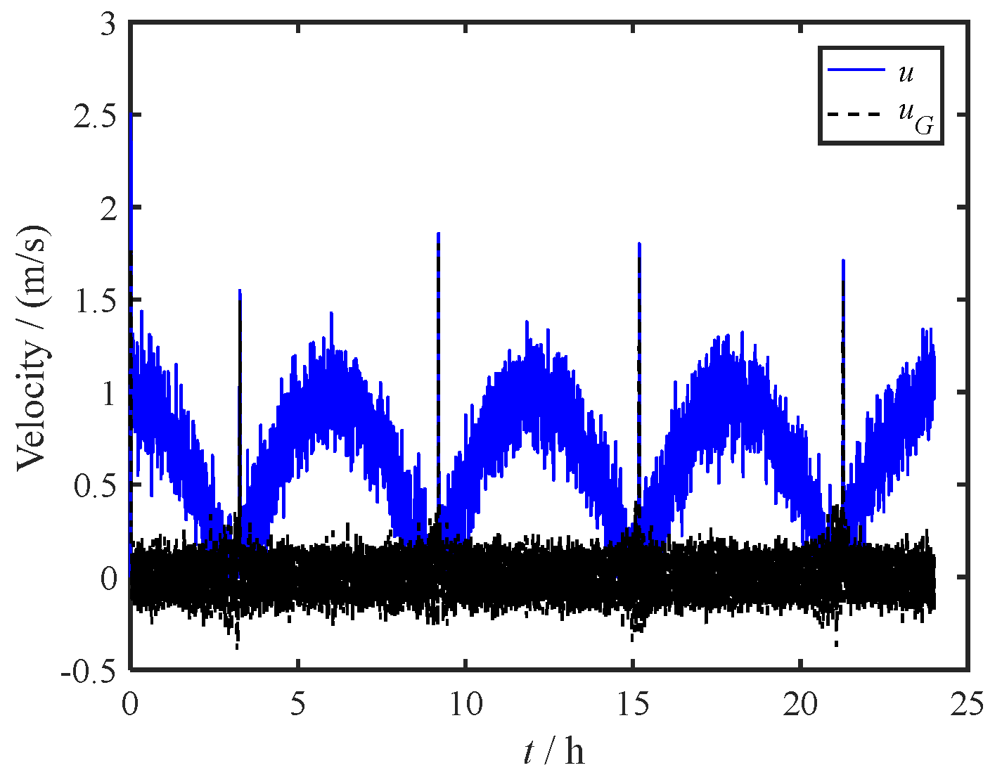
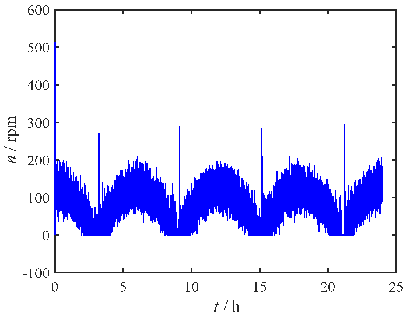
4.2 Simulation under 24-hour Tidal Current
To further validate the applicability and scalability of the proposed method, we conducted a simulation that modeled the positioning control of the USV near a river estuary under tidal currents over a 24-hour duration. Tidal forces cause the tide to rise and fall twice daily, leading to specific patterns in flow velocity and direction. The models for simulating these tidal changes are as follows:
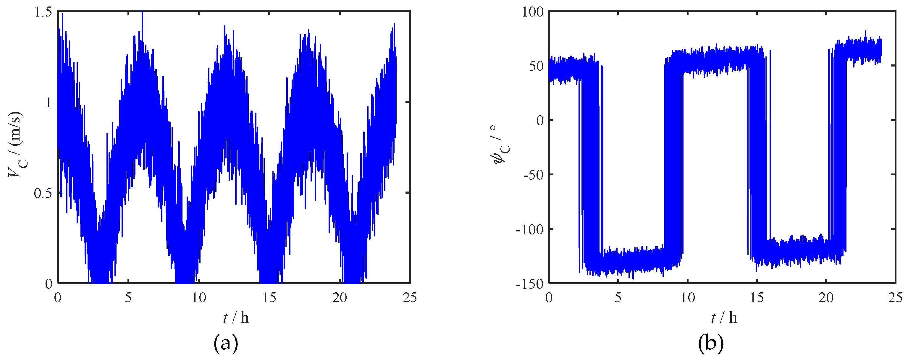
In the above model, the current velocity, excluding noise perturbations, varies periodically as an absolute value cosine curve with a 12-hour period. Similarly, excluding noise and a constant 20° deflection over 24 hours, the current direction experiences a 180° phase shift according to the 12-hour tidal cycle. The 24-hour variation curves for both velocity and direction are illustrated in
Figure 10.
The simulation step size was set to 0.1s, while all other settings remained consistent with those in Simulation 1.
Figure 11,
Figure 12,
Figure 13,
Figure 14 and
Figure 15 illustrate the operational status of the control system over a 24-hour period.
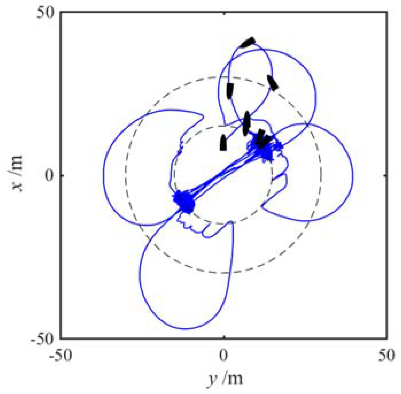
Each time the flow direction experiences a 180° reversal, the single-propeller vessel, constrained by physical limitations such as turning time and radius, requires additional time and space to re-establish positional stabilization control. As a result, in
Figure 11, aside from the initial deviation, the USV briefly deviated from the anchoring point 4 times, primarily due to the periodic reversal of tidal currents. Fortunately, these deviations remained within an acceptable range.
Over all, based on the simulation results presented in
Figure 11,
Figure 12,
Figure 13,
Figure 14 and
Figure 15, it can be conclusively determined that the control algorithm devised in this study demonstrates effective performance even within a periodically fluctuating tidal current environment.
5. Conclusions and Outlook
This paper presents a control method, which named as the “virtual anchor” to tackle the challenges faced by underactuated USVs when maintaining a stationary position at sea, especially under the influence of sea currents. This innovative approach enables high-precision stationary control of the USV. Drawing inspiration from the anchoring mechanism of a ship's anchor chain, the USV can automatically adjust its heading to face the oncoming current and modify its thrust to maintain a stationary position relative to the ground. This significantly enhances stability and precision, particularly in unpredictable current environments.
Through numerical simulation experiments encompassing scenarios with multiple disturbances, and 24-hour tidal current variations, the efficacy and dependability of the control algorithm were validated. The simulation outcomes revealed that the USV could navigate along the anticipated trajectory, ensuring precise anchoring, while also providing accurate real-time estimations of the prevailing sea current direction. Despite adverse conditions such as random sea current disturbances and rudder angle dead zones, the control system exhibited good performance, highlighting its remarkable robustness.
Based on the findings of this study, future research will focus on further functional optimization and conducting sea trials on actual vessels. Additionally, we plan to incorporate theoretical methods for precise current velocity estimation and extend the overall approach to dual-thrust differential unmanned boats. These efforts are expected to enhance the capabilities of unmanned boats during maritime operations and provide crucial technical support for various applications, including marine resource development and environmental monitoring.
Author Contributions
Theoretical derivation, simulation test, and first draft writing, Zihe Qin ; Paper revision, Feng Zhang; Paper editing, Xu Wenlin and Chen Yu; Paper review, Jinyu Lei.
Funding
This research was funded by Natural Science Foundation of Fujian Province, grant number 2023J011570, 2023J011573, 2023J011402; 2023 Annual Fuzhou Marine Research Institute "Top Talents Recruitment" Science and Technology Project, No. 2023F06;The Science and Technology Key Project of Fuzhou, No. 2022-ZD-021;
Data Availability Statement
Data is available on request.
Conflicts of Interest
The authors declare no conflict of interest.
References
- Fu M, Zhang G, Xu Y, et al. Discrete-time adaptive predictive sliding mode trajectory tracking control for dynamic positioning ship with input magnitude and rate saturations[J]. Ocean Engineering, 2023, 269: 113528. [CrossRef]
- Ahani A, Ketabdari M J. Alternative approach for dynamic-positioning thrust allocation using linear pseudo-inverse model[J]. Applied Ocean Research, 2019, 90: 101854.
- Aydin C, Unal U O, Sarioz K. Computation of environmental loads towards an accurate dynamic positioning capability analysis[J]. Ocean Engineering, 2022, 243: 110201.
- Zou Z, Zheng M. Design and stabilization analysis of luxury cruise with dynamic positioning systems based on sampled-data control[J]. Math. Biosci. Eng, 2023, 20: 14026-14045.
- Pereira A, Das J, Sukhatme G S. An experimental study of station keeping on an underactuated ASV[C]//2008 IEEE/RSJ International Conference on Intelligent RObots and Systems. IEEE, 2008: 3164-3171.
- Pereira A, Das J, Sukhatme G S. An experimental study of station keeping on an underactuated ASV[C]//2008 IEEE/RSJ International Conference on Intelligent RObots and Systems. IEEE, 2008: 3164-3171.
- Gao X, Li T. Dynamic Positioning Control for Marine Crafts: A Survey and Recent Advances[J]. Journal of Marine Science and Engineering, 2024, 12(3): 362.
- Gao S, Liu C, Tuo Y, et al. Augmented model-based dynamic positioning predictive control for underactuated unmanned surface vessels with dual-propellers[J]. Ocean Engineering, 2022, 266: 112885. [CrossRef]
- Yuan W, Rui X. Deep reinforcement learning-based controller for dynamic positioning of an unmanned surface vehicle[J]. Computers and Electrical Engineering, 2023, 110: 108858.
- Zheng M, Yang S, Li L. Stability analysis and TS fuzzy dynamic positioning controller design for autonomous surface Vehicles based on sampled-data control[J]. IEEE Access, 2020, 8: 148193-148202.
- Sarda E I, Qu H, Bertaska I R, et al. Station-keeping control of an unmanned surface vehicle exposed to current and wind disturbances[J]. Ocean Engineering, 2016, 127: 305-324.
- de Oliveira É L, Donha D C, de T Fleury A, et al. Station-keeping of a ROV under wave disturbance: Modeling and control design[J]. Proceedings of the Institution of Mechanical Engineers, Part M: Journal of Engineering for the Maritime Environment, 2023, 237(2): 455-477.
- Walker K L, Stokes A A, Kiprakis A, et al. Feed-forward disturbance compensation for station keeping in wave-dominated environments[C]//OCEANS 2023-Limerick. IEEE, 2023: 1-7.
- Peng Z, Jiang Y, Liu L, et al. Distributed optimization for coordinated dynamic positioning of multiple surface vessels based on asymptotically stable ESOs[J]. Ocean Engineering, 2022, 246: 110507.
- Panagou D, Kyriakopoulos K J. Dynamic positioning for an underactuated marine vehicle using hybrid control[J]. International Journal of Control, 2014, 87(2): 264-280.
- Liu C, Zhang Y, Gu M, et al. Experimental Study on Adaptive Backstepping Synchronous following Control and Thrust Allocation for a Dynamic Positioning Vessel[J]. Journal of Marine Science and Engineering, 2024, 12(2): 203. [CrossRef]
- Chen H, Peng Y, Zhang D, et al. Dynamic positioning for underactuated surface vessel via L1 adaptive backstepping control[J]. Transactions of the Institute of Measurement and Control, 2021, 43(2): 355-370.
- Tang L, Lin W, Wang Y, et al. Robust adaptive tracking control for dynamic positioning ships subject to dynamic safety constraints and actuator saturation[J]. Journal of Ocean Engineering and Science, 2023.
- Pengbo L I, Mingzhe Y, Jinchao X, et al. Station Keeping Guidance Strategy Based on Course Constraint for Unmanned Surface Vehicles[J]. Journal of Shanghai Jiaotong University, 2020, 54(9): 987.
- Qu Y, Cai L. Nonlinear station keeping control for underactuated unmanned surface vehicles to resist environmental disturbances[J]. Ocean Engineering, 2022, 246: 110603.
- Faltinson O, M. Hydrodynamics of high-speed marine vehicles[M]. Cambridge University, Press,2006.
- LIU W, SUI Q, XIAO H, et al. Sliding backstepping control for ship course with nonlinear disturbance observer[J]. JOURNAL OF INFORMATION &COMPUTATIONAL SCIENCE, 2011, 8(16): 3809-3817.
- Fossen T I, Perez T. Kalman filtering for positioning and heading control of ships and offshore rigs[J]. IEEE Control Systems Magazine, 2009, 29(6): 33-46. [CrossRef]
- Do K D, Pan J. Control of Ships and Underwater Vehicles[M]. New York: Springer, 2009.
- Cao Q, Poulakakis I. Quadrupedal bounding with a segmented flexible torso: passive stability and feedback control[J]. Bioinspiration & biomimetics, 2013, 8(4): 046007. [CrossRef]
- Zihe Qin. The Study on Motion Control and Swarm Coordinated Planning for Unmanned Surface Vehicles (USV)[D]. Harbin Engineering University, 2018.
|
Disclaimer/Publisher’s Note: The statements, opinions and data contained in all publications are solely those of the individual author(s) and contributor(s) and not of MDPI and/or the editor(s). MDPI and/or the editor(s) disclaim responsibility for any injury to people or property resulting from any ideas, methods, instructions or products referred to in the content. |
© 2024 by the authors. Licensee MDPI, Basel, Switzerland. This article is an open access article distributed under the terms and conditions of the Creative Commons Attribution (CC BY) license (http://creativecommons.org/licenses/by/4.0/).
