Preprint
Article

Point of Common Connection Voltage Modulated Direct Power Control with Disturbance Observer to Increase of Renewable Energy Acceptance in Power System

Altmetrics

Downloads

51

Views

26

Comments

0

A peer-reviewed article of this preprint also exists.

This version is not peer-reviewed

Submitted:

06 September 2024

Posted:

09 September 2024

You are already at the latest version

Alerts
Abstract
As the penetration of renewable energies increases, their acceptance of the power grid system is becoming an important issue. In the case of South Korea, a 22.9kV transformer is frequently utilized to reduce the power loss of the generated renewable energy transmission, so the power quality at the point of common connection (PCC) is inevitably influenced by the nonlinearity of the transformer and the uncertainty of the inductance and resistance of the transmission line. In this paper, we present a point of common connection voltage-modulated direct power control (PCCVM-DPC) system that enhances power quality at the PCC. First, we present the mathematical dynamics of active and reactive power at the PCC side, which contains the step-up transformer’s nonlinearity, the grid voltage harmonics, and the parameter uncertainties. By analyzing the disturbance terms of the PCCVM-DPC system, we present the disturbance observer (DOB) for the PCCVM-DPC system. To assess the efficacy of our approach, we perform comparative studies of the PCCVM-DPC without DOB and PCCVM-DPC with DOB by constructing the simulation environment based on the commercial step-up transformer and ESS inverter datasheet. We have validated that the active and reactive power control performance of the PCCVM-DPC with DOB outperforms the PCCVM-DPC without DOB from the observation that the current total harmonic distortion reduced by more than 40% compared to the PCCVM-DPC without the DOB.
Keywords: 
Subject: Engineering  -   Electrical and Electronic Engineering

1. Introduction

At the end of 2023, global renewable power capacity had reached 3870 GW. Photovoltaic power generation accounted for the largest share of the global total, with a capacity of 1419 GW [1]. As the penetration of renewable energies is increasing into the power grid system, irregular power generation from the renewable energy system is starting to raise grid instability. To remedy these issues, charging and discharging strategies of a grid-connected energy storage system (ESS) have been researched [2,3,4] coupled with the power grid [5]. Therefore, an active and reactive power control performance of the grid-connected ESS inverter system can impact the power fluctuation of the point of common connection (PCC) side, and it can cause inefficiency of the power grid system [6]. Specifically, an amount of active and reactive power flowing through the electrical substation can not exceed the installed transformer capacity, so the excessive power fluctuation caused by the grid-connected ESS inverter system can reduce the utilization efficiency of the installed substation system. Therefore, research on the inverter control performance enhancement to reduce power fluctuation can provide a practical solution to enhance renewable energy acceptance in the grid system while not increasing the current electric substation capacity.
A total harmonic distortion (THD) of the phase currents and voltages at the PCC side directly impacts the electronic device’s lifetime [7,8,9], so in the case that the 3-phase voltages can be considered as the balanced conditions, the performance of the grid-connected ESS inverter control can be evaluated with the THD. The voltage harmonics are caused by the nonlinear loads and inadequately generated voltage from the generators [10], so it can be regarded as an uncontrollable factor to the inverter control system except for the weak grid conditions. Therefore, reducing the THD of the phase currents from the given voltage harmonic condition is important while performing active and reactive power control.
A vector current control (VCC) method is one of the control methods to stabilize a voltage source inverter (VSI). From the desired active and reactive reference given from the PMS, the set point of the d and q-axis currents can be calculated, and a proportional-integral (PI) control structure with a feedback-linearization controls the phase currents to track the set points. So the power control of the VSI can be performed [11,12,13]. In this control scheme, a Park transformation is needed to convert 3-phase alternating grid currents/voltages to the d-q frame signals, and it needs a phase angle of the grid. Although a phase-locked loop (PLL) estimates the phase angle VCC [14], it is reported that the estimated position contains a delayed phase during the transient regions [15,16]. Therefore, the non-uniform estimation result of the phase angle at the transient regions impacts the performance of the VCC. Furthermore, the harmonics of the phase voltages directly impact the estimated result, which can destabilize the grid system [17,18,19]. Furthermore, the PI control of the VCC does not guarantee the robustness for unknown uncertainties such as parameter variation, so it is not easy to perform currents decoupling [20,21]. In [22], disturbance observer-based inverter control is proposed by assuming that the disturbance of the grid system only has a sinusoidal waveform that oscillates at the fundamental frequency, particularly when the grid voltage does not include harmonics. However, to the best of the author’s knowledge, as the step-up transformer is going to be included in the grid-connected ESS inverter system, other structures of the disturbance observer should be developed to estimate the harmonics components.
Recently, a grid voltage modulation direct power control (GVM-DPC) [23] has been proposed to reduce the dependency on the PLL. From the comparative study between the VCC and the GVM-DPC, the outperformed power control performance in the transient region has been verified [24,25]. To enhance the robustness of the GVM-DPC, sliding mode control (SMC) with the zero-dimensional sliding surface is applied and shows the enhanced performance [26]. There exist researches that apply the robust controller to less affected by chattering of the SMC, targeting the VCC or PLL system [27,28,29,30,31]. Although the sliding mode-based control structure has an outperformed performance for the unknown and bounded disturbance of the system, to the best of our experience, a heuristic gain tuning process is needed for the control design step. Furthermore, there is no analytical research on the disturbances components in the case that the step-up transformer is included in the GVM-DPC system. For that reason, in this paper, we present a point of common connection voltage-modulated direct power control (PCCVM-DPC) system by considering the nonlinearity of the transformer characteristics. By analyzing the disturbance terms of the PCCVM-DPC system, we newly present the disturbance observer and its compensation logic, which has a well-known gain-tuning process due to its linear structure. To assess the efficacy of our approach, we perform comparative studies of the conventional GVM-DPC and the PCCVM-DPC by simulating the transformer based on the commercial transformer datasheet. The outperformed power quality at the PCC of the proposed method shows its effectiveness.
The main contribution of this paper is summarized as follows:
  • Modeling of the active and reactive power dynamics for the PCCVM-DPC, including the step-up transformer.
  • Analysis of the disturbances that existed in the PCCVM-DPC system.
  • Disturbance observer design and adaptive disturbance rejection control structure for the PCCVM-DPC system.
  • Validation results performed in the transformer included simulation environments.
The remainder of this paper consists of Section II, which describes the system modeling of the ESS/VSI including the transformer nonlinear characteristics and the disturbance observer and the PCCVM-DPC, Section III for the validation results, and Section IV for the conclusion.

2. Main Contents

To reduce the power fluctuation and the total harmonic distortion (THD) of the phase currents at the point of common connection (PCC), in this section, we newly derive the instantaneous active and reactive power dynamics at the PCC, including the step-up transformer characteristics. We analyze the disturbances that hinder the power tracking performance from the newly derived dynamics. Furthermore, we newly present a disturbance observer and a point of common connection voltage modulated direct power control (PCCVM-DPC) structure, including the disturbance rejection control. And, the closed-loop transfer functions are analyzed to expect the stability and effectiveness of the proposed method.

2.1. Active and Reactive Power Dynamics at the PCC Including Step-Up Transformer

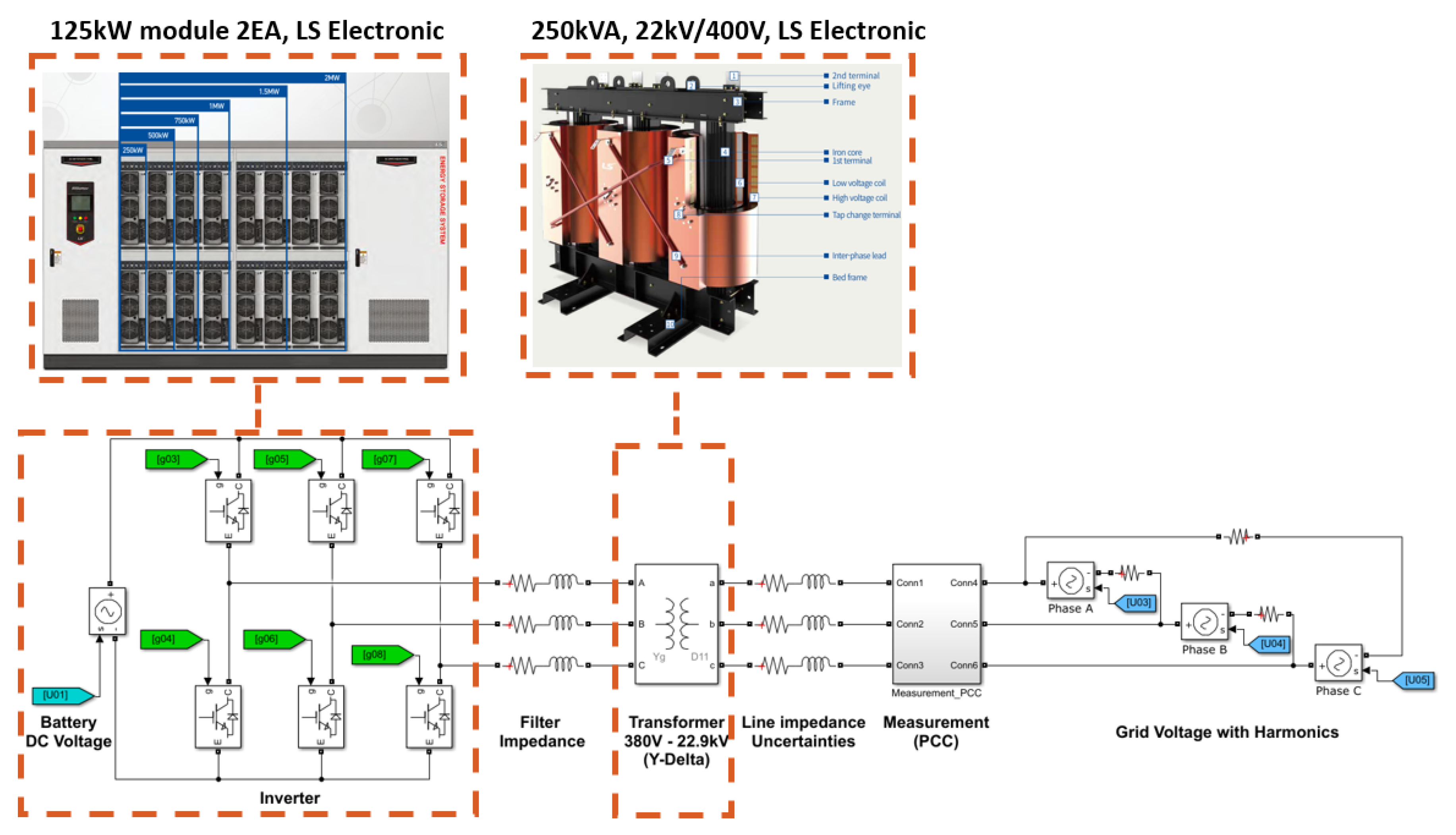
Figure 1 shows the schematic of a voltage source inverter (VSI), connected to the grid system. Let us distinguish the 3-phase system by defining j as j { a , b , c } . Let us define the output voltage of the VSI as u j , j { a , b , c } , the line filter inductance as L f , j and the resistance as R f , j . Let us define the currents flowing from the IGBT of the inverter to the beginning of the low voltage bushing as i i n v , j . Let us define the voltage at the end of the line filter as v i n v , j . Then, the voltage drop equation from u j to the end of R f , j is represented as
u j = L f , j d d t i i n v , j + R f , j i i n v , j + v i n v , j , j { a , b , c } .
Let us define the line resistance including the transformer’s primary winding as R p , j , the line inductance including the transformer’s primary winding as L p , j and terminal voltage of the primary part as v p , j , j { a , b , c } . Then, the voltage drop equation from v i n v , j to the end of R p , j is represented as
v i n v , j = L p , j d d t i i n v , j + R p , j i i n v , j + v p , j .
Let us define the primary winding current as i p , j , the number of primary winding turns as n p , the secondary winding current as i s , j , the secondary voltage of the transformer as v s , j and the number of secondary winding turns as n s . Then, the current and voltage relationship of the step-up transformer is represented as
i s , j = n p n s i p , j , v s , j = n s n p v p , j , j { a , b , c } .
To consider the hysteresis characteristic of the transformer, let us define the excitation current as i e x c , j , core loss resistance as R e x c , j and magnetization inductance as L e x c , j , j { a , b , c } . Then, the relationship between i p , j and i i n v , j is represented as
i p , j = i i n v , j i e x c , j , j { a , b , c } .
Let us define the line resistance including the transformer’s secondary winding as R s , j , the line inductance including the transformer’s secondary winding as L s , j . Let us define the flowing current at the PCC as i p c c , j , and the measured voltage at the PCC as v p c c , j , j { a , b , c } . Then, we can represent the voltage drop equation from v s , j to the end of R s , j as
v s , j = L s , j d d t i p c c , j + R s , j i p c c , j + v p c c , j , j { a , b , c } .
By considering that i s , j = i p c c , j and plugging (1)-(4) into (5), we can represent the dynamics of i p c c , j with respect to u j as
u j = L f , j n s n p + L p , j n s n p + L s , j n p n s d d t i p c c , j + R f , j n s n p + R p , j n s n p + R s , j n p n s i p c c , j + L f , j d d t i e x c , j + L p , j d d t i e x c , j + R f , j i e x c , j + R p , j i e x c , j + n p n s v p c c , j , j { a , b , c } .
For the simplicity of the notation, let us define the equivalent inductance as L e q , j , the resistance as R e q , j , uncertainty caused by the leakage currents of the transformer as Δ e x c , j , such that
L e q , j = L f , j n s n p + L p , j n s n p + L s , j n p n s , R e q , j = R f , j n s n p + R p , j n s n p + R s , j n p n s , Δ e x c , j = L f , j d d t i e x c , j + L p , j d d t i e x c , j + R f , j i e x c , j + R p , j i e x c , j , j { a , b , c } .
By using the Clarke transformation, current dynamics in the stationary reference frame are represented as
L e q , k d d t i p c c , k = R e q , k i p c c , k + u k Δ e x c , k n p n s v p c c , k , k { α , β } .
Since electrical parameters have an uncertainty according to the temperature, let us separate the nominal values ( R 0 , L 0 ) and parameter uncertainties ( Δ R k , Δ L k ), such that
L e q , k = L 0 + Δ L k , R e q , k = R 0 + Δ L k , k { α , β } .
By replacing L e q , k and R e q , k of (8) with (9), we obtain
d d t i p c c , k = R 0 L 0 i p c c , k + 1 L 0 u k + 1 L 0 Δ V k 1 L 0 n p n s v p c c , k ,
where
Δ V k = Δ R k i p c c , k Δ L k d d t i p c c , k Δ e x c , k , k { α , β } .
The PCC voltages v p c c , k can be decomposed as the fundamental frequency component and the harmonics, so let us define V g f as the magnitude of the fundamental grid voltage, and ω f is the fundamental frequency of the grid voltage. Then, we can represent v p c c , k as
v p c c , α = V g f cos ω f t + α ( t ) , v p c c , β = V g f sin ω f t + β ( t ) ,
where α ( t ) and β ( t ) indicate harmonic components. The time derivative of (11) is represented as
d d t v p c c , α = ω f V g f sin ( ω f t ) + α ˙ ( t ) = ω f v p c c , β + Δ v p c c , α d d t v p c c , β = ω f V g f cos ( ω f t ) + β ˙ ( t ) = ω f v p c c , α + Δ v p c c , β
where
Δ v p c c , α = ω f β ( t ) + α ˙ ( t ) , Δ v p c c , β = ω f α ( t ) + β ˙ ( t ) .
Let us define the instantaneous fundamental components of the real and reactive powers at the PCC as P p c c and Q p c c , where
P p c c = 3 2 v p c c , α i p c c , α + v p c c , β i p c c , β , Q p c c = 3 2 v p c c , β i p c c , α v p c c , α i p c c , β .
A time derivative of (13) are expressed as follows:
d d t P p c c = 3 2 d v p c c , α d t i p c c , α + v p c c , α d i p c c , α d t + d v p c c , β d t i p c c , β + v p c c , β d i p c c , β d t d d t Q p c c = 3 2 d v p c c , β d t i p c c , α + v p c c , β d i p c c , α d t d v p c c , α d t i p c c , β v p c c , α d i p c c , β d t .
By substituting (10), (12) by d d t v p c c , k , d d t i p c c , k of (14), the dynamics of P p c c and Q p c c are represented as
d d t P p c c = R 0 L 0 P p c c ω f Q p c c + 1 L 0 d P + 3 2 L 0 ( v p c c , α u α + v p c c , β u β ) d d t Q p c c = R 0 L 0 Q p c c + ω f P p c c + 1 L 0 d Q + 3 2 L 0 ( v p c c , β u α v p c c , α u β )
where
d P = 3 2 { L 0 Δ v p c c , α i p c c , α + L 0 Δ v p c c , β i p c c , β + v p c c , α Δ V α + v p c c , β Δ V β n p n s ( v p c c , α 2 + v p c c , β 2 ) } d Q = 3 2 { L 0 Δ v p c c , β i p c c , α L 0 Δ v p c c , α i p c c , β + v p c c , β Δ V α v p c c , α Δ V β } .
Let us define PCCVM-DPC inputs as u P and u Q , which is similar to the GVM-DPC system [26], where
u P u Q = v p c c , α u α + v p c c , β u β v p c c , β u α + v p c c , α u β .
By plugging (17) into (15), we can obtain concise active and reactive power dynamics as
d d t P p c c = R 0 L 0 P p c c ω f Q p c c + 3 2 L 0 u P + 1 L 0 d P d d t Q p c c = R 0 L 0 Q p c c + ω f P p c c 3 2 L 0 u Q + 1 L 0 d Q .
Therefore, the harmonics of the PCC voltages, uncertainties of electric parameters, and the nonlinearity of the transformer are represented as lumped disturbance terms of the active and reactive power dynamics. Based on these active and reactive power dynamics, the disturbance observer for the PCCVM-DPC system and disturbance rejection control structure are presented in the next subsections.

2.2. Disturbance Observer Design for PCCVM-DPC

Since multiple uncertainties are included in the disturbance terms d P and d Q of (18), it is expected that the proper disturbance estimation and compensation control logic can reduce the power fluctuation during the power control, which enhances the acceptance of the grid-connected ESS. In this section, we propose the structure of the disturbance observer for the PCCVM-DPC system and its stability analysis. To design the proposed DOB, let us define the estimated value of d P , d Q as d ^ P , d ^ Q . Let us define the estimated value of P p c c , Q p c c as P ^ p c c , Q ^ p c c , which are used for disturbance estimation. Let us define the estimation error of d P , d Q as d ˜ P , d ˜ Q , and the estimation error of P p c c , Q p c c as P ˜ p c c , Q ˜ p c c , such that
P ˜ p c c = P p c c P ^ p c c , Q ˜ p c c = Q p c c Q ^ p c c d ˜ P = d P d ^ P , d ˜ Q = d Q d ^ Q .
Let us define the observer gains as l p and l i . Then, from (18), the structure of DOB for the PCCVM-DPC system can be designed as
d d t P ^ p c c = R 0 L 0 P p c c ω f Q p c c + 3 2 L 0 u P + 1 L 0 d ^ P d ^ P = L 0 ( l p P ˜ p c c + l i P ˜ p c c d τ ) d d t Q ^ p c c = R 0 L 0 Q p c c + ω f P p c c 3 2 L 0 u Q + 1 L 0 d ^ Q d ^ Q = L 0 ( l p Q ˜ p c c + l i Q ˜ p c c d τ ) .
From now on, let us describe the stability analysis and the frequency response analysis of the proposed DOB structure. From (18) and (20), we obtain following equation
d d t P ˜ p c c = l p P ˜ p c c l i P ˜ p c c d τ + L 0 1 d P , d d t Q ˜ p c c = l p Q ˜ p c c l i Q ˜ p c c d τ + L 0 1 d Q .
By defining Laplace transform as L ( · ) , we can represent each results of Laplace transform for P ˜ p c c , d ˜ P , d P , Q ˜ p c c , d ˜ Q and d Q as P ˜ p c c ( s ) = L ( P p c c ) , D ˜ P ( s ) = L ( d ˜ P ) and D P ( s ) = L ( d P ) , Q ˜ p c c ( s ) = L ( Q p c c ) , D ˜ Q ( s ) = L ( d ˜ Q ) and D Q ( s ) = L ( d Q ) . From (21), we obtain
P ˜ p c c ( s ) = L 0 1 s s 2 + l p s + l i D P ( s ) , Q ˜ p c c ( s ) = L 0 1 s s 2 + l p s + l i D Q ( s ) .
By performing time derivative of d ˜ P in (19), we obtain following equations
d ˜ ˙ P = d ˙ P d ^ ˙ P = d ˙ P L 0 ( l p P ˜ ˙ p c c + l i P ˜ p c c ) d ˜ ˙ Q = d ˙ Q L 0 ( l p Q ˜ ˙ p c c + l i Q ˜ p c c ) .
From the Laplace transform of (23) and substituting P ˜ p c c as (22), the transfer function between d P and d ˜ P are represented as
D ˜ P D P = 1 l p s + l i s 2 + l p s + l i = s 2 s 2 + l p s + l i .
To discuss the gain tuning process of l p and l i , let us represent (24) as
D ˜ P ( s ) D P ( s ) = K o s 2 ( s / p o 1 + 1 ) ( s / p o 2 + 1 ) ,
where p o 1 = l p + l p 2 4 l i 2 , p o 2 = l p l p 2 4 l i 2 and K o = l i 1 .

2.3. Disturbance Rejection Control of the PCCVM-DPC system
Let us define the desired active power at the PCC as P p c c d , and the reactive power command as Q p c c d . Then, we can define tracking errors of each power as
e P = P p c c d P p c c , e Q = Q p c c d Q p c c .
By differentiating (26) and plugging (18), we obtain
e ˙ P = P ˙ p c c d P ˙ p c c = P ˙ p c c d + R 0 L 0 P p c c + ω f Q p c c 3 2 L 0 u P 1 L 0 d P , e ˙ Q = Q ˙ p c c d Q ˙ p c c = Q ˙ p c c d + R 0 L 0 Q p c c ω f P p c c + 3 2 L 0 u Q 1 L 0 d Q .
Let us represent the control inputs u P and u Q as
u P = u e q , P 2 L 0 3 u ˜ P , u Q = u e q , Q + 2 L 0 3 u ˜ Q
where u e q , j , j { P , Q } are equivalent feedback control law, and u ˜ j , j { P , Q } are the disturbance rejection control law, such that
u e q , P = 2 3 d ^ P + 2 L 0 3 R 0 L 0 P p c c + ω f Q p c c + P ˙ p c c d , u e q , Q = 2 3 d ^ Q 2 L 0 3 R 0 L 0 Q p c c ω f P p c c + Q ˙ p c c d ,
u ˜ P = k p e P k i e P d τ , u ˜ Q = k p e Q k i e Q d τ
where k p and k q are the control gains. By substituting u P and u Q of (27) with (28)-(30), the tracking error dynamics of PCCVM-DPC system with the proposed control method are represented as
e ˙ P = k p e P k i e P d τ 1 L 0 d ˜ P , e ˙ Q = k p e Q k i e Q d τ 1 L 0 d ˜ Q .
By defining Laplace transform as L ( · ) , we can represent each results of Laplace transform for e P and e Q as E P = L ( e P ) , E Q = L ( e Q ) . Then, we can represent the transfer function from d ˜ j to e j , j { P , Q } as
E j D ˜ j = 1 L 0 s s 2 + k p s + k i = K c s ( s / p c 1 + 1 ) ( s / p c 2 + 1 )
where K c = ( L 0 p c 1 p c 2 ) 1 .
Remark 1.
In the case that the disturbance observer is not utilized for the PCCVM-DPC system, d ^ P and d ^ Q are regarded as 0, which means D ˜ j = D j . Therefore, from (19) and (32), we can obtain the closed-loop transfer function between d j to e j j { P , Q } as
E j D j = K c s ( s / p c 1 + 1 ) ( s / p c 2 + 1 ) .
From (25) and (32), we obtain the closed-loop transfer function of the proposed PCCVM-DPC control method as
E j D j = K o K c s 3 ( s / p o 1 + 1 ) ( s / p o 2 + 1 ) ( s / p c 1 + 1 ) ( s / p c 2 + 1 ) .
From K o of (25), we can expect that the robustness of the proposed PCCVM-DPC with DOB for the disturbance is improving as l i is increasing. Compared to PCCVM-DPC without the DOB, which is discussed in Remark 1, we expect that the power control performance of the proposed PCCVM-DPC with the DOB outperforms the one without the DOB. The gain tunning of the second order transfer function can be performed by setting the natural frequency and the damping ratio.
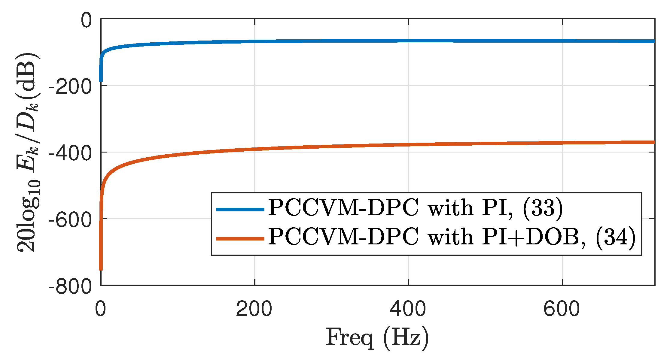
Figure 2. Closed-loop bode plot of PCCVM-DOC with PI and PI+DOB
Preprints 117496 g002
Figure 3. Schematic of the Simulink/MATLAB simulation environments
Preprints 117496 g003

3. Validation

3.1. Simulation Environment

To validate the proposed PCCVM-DPC with the DOB, we constructed the simulation environment with Simulink/Simscape specialized power systems library as shown in Figure 3. The fundamental frequency of the grid voltages is set as f 0 =60 H z . To simulate the characteristics of the IGBTs, the simulation step time is set as T s = 100 n s , and the backward-Euler discrete method is utilized for the inverter and transformer of the simulator. The pulse width modulated (PWM) frequency of the inverter is set as f p w m = 10 k H z , the PWM signals are center-aligned and the rising time delay for the complementary PWM signals is set as t d = 6 μ s . The measurement sampling frequency of the i p c c , j , j { a , b , c } and the control frequency are set as f c t r l = 20 k H z , and forward Euler method is utilized for the controller and observer. We set the step-up transformer and the ESS inverter parameters by referring to the LS electronic product datasheets and the IEC 60076-11 (Transformer: 250kVA 400V/22kV-60Hz, ESS inverter: two modules of 125 kW inverter) [32,33,34]. Table 1 shows the simulation configuration parameters and the power grid system parameters illustrated in Figure 1. By considering the fundamental frequency of the grid voltages and the DC-offset of the closed loop bode plot, we selected the control gains to have duplicated poles, and its natural frequencies were set as 420 Hz, such as p c 1 = p c 2 = 2 π × 420 . Furthermore, observer gains were also selected to have duplicated poles, and their natural frequencies were set as 1200 Hz, such as p o 1 = p o 2 = 2 π × 1200 .
Figure 2 shows the comparative bode plot results between PI (33) and PI+DOB (34) based on the selected k p , k i , l p and l i . The blue line indicates the amplitude of (33), and the red line indicates the amplitude of (34). From (16), we can expect that the unknown disturbances consist of sinusoidal harmonics in which the fundamental frequency is 60 H z , and from the bode plot, we can expect that the power tracking performance of the proposed PI+DOB is robust to the unknown disturbances compared to the conventional PI control structure.

3.2. Validation Results for Different Voltage Harmonic Conditions

The total harmonic distortion of the voltage is one of the important factors in operating power grid devices. We intentionally injected various harmonics into the grid voltages to validate the control performance for the disturbances. These harmonics are represented as α ( t ) , β ( t ) of the (11) and consequently changing d P and d Q of (16).
  • Case 1-1 : α ( t ) ≃ 0 and β ( t ) 0 .
  • Case 2-1 : α ( t ) = 0 . 015 cos ( 5 × 2 π f 0 t ) + 0 . 025 cos ( 7 × 2 π f 0 t ) and
    β ( t ) = 0 . 015 sin ( 5 × 2 π f 0 t ) + 0 . 025 sin ( 7 × 2 π f 0 t ) .
  • Case 3-1 : α ( t ) = 0 . 03 cos ( 5 × 2 π f 0 t ) + 0 . 05 cos ( 7 × 2 π f 0 t ) and
    β ( t ) = 0 . 03 sin ( 5 × 2 π f 0 t ) + 0 . 05 sin ( 7 × 2 π f 0 t ) .
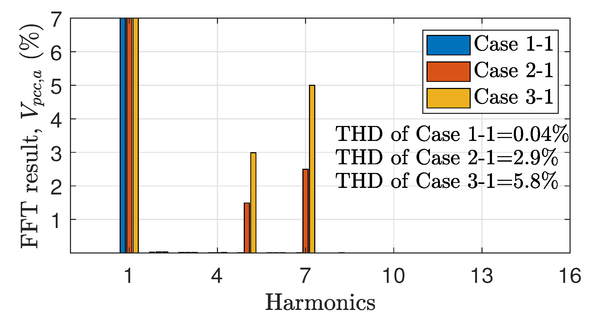
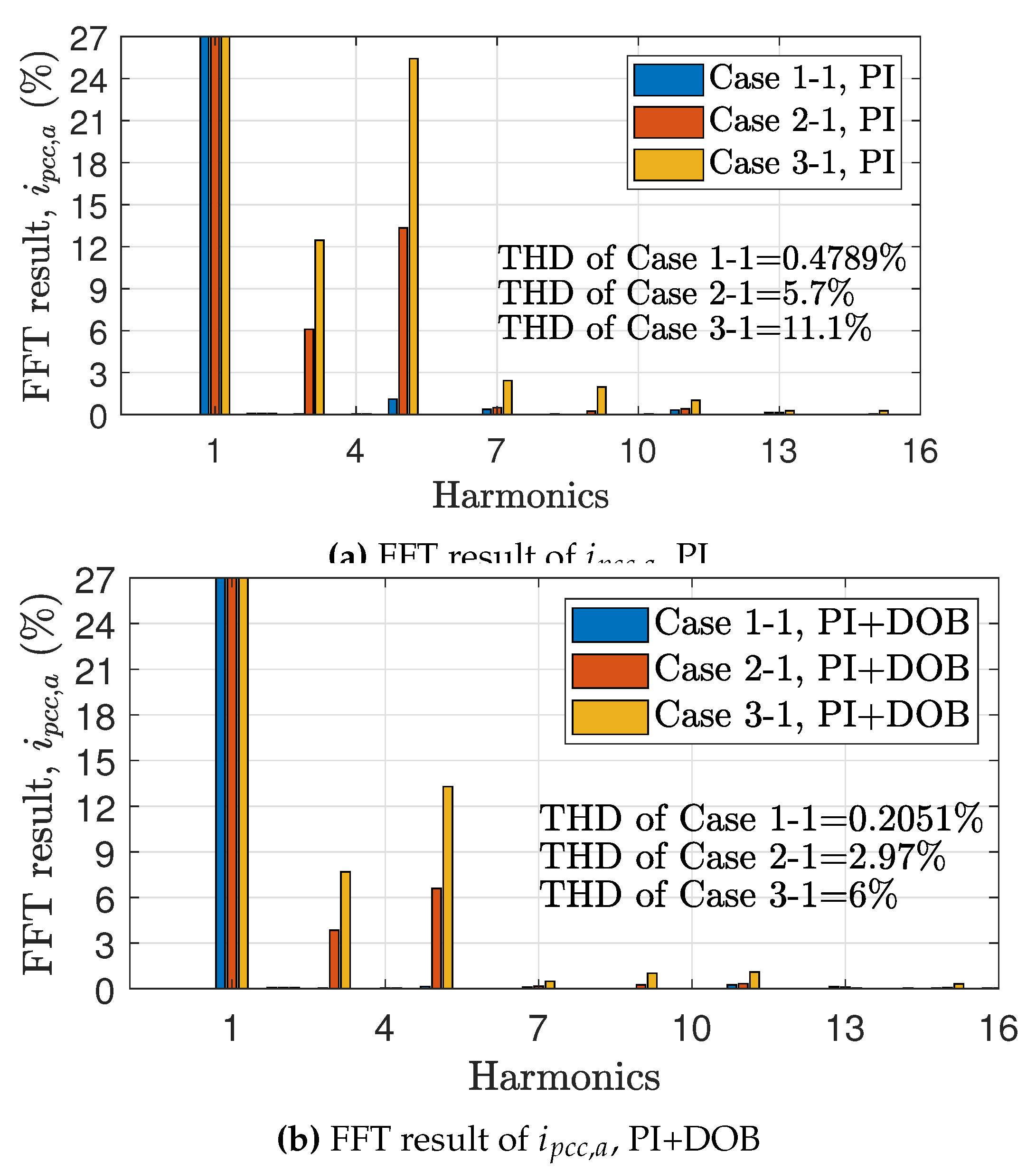
Figure 4 shows the total harmonic distortion (THD) of each case and fast Fourier transform (FFT) results of V p c c , a . Active power command of the power conversion system (PCS) is applied up to 125 kW, which is the maximum value of the one power electronics building block of LS electronics PCS products. The blue colored line of this subsection indicates the validation results of Case 1-1, the red colored line indicates the results of Case 2-1, and the yellow colored line indicates the result of Case 3-1, respectively.
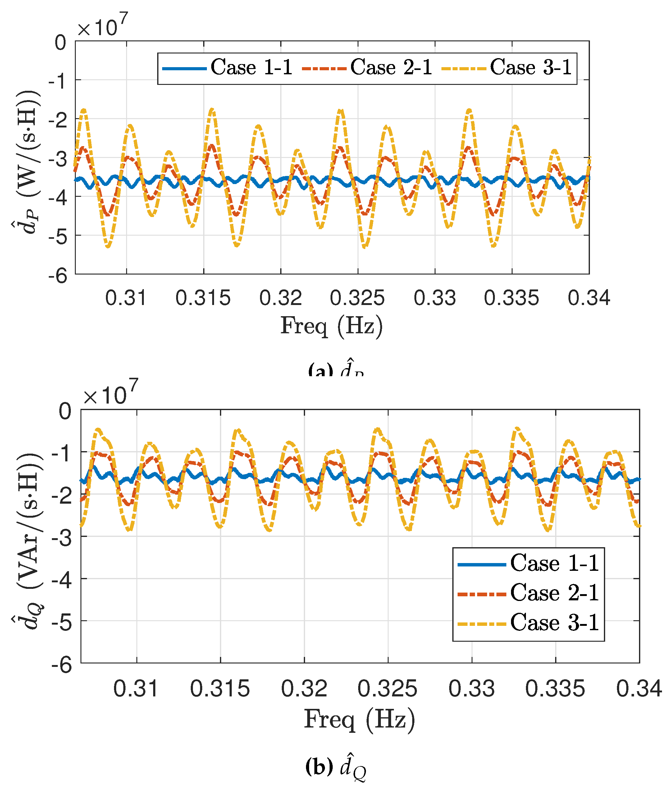
Figure 5 show the estimated disturbance results. As the amplitude of the harmonics is increasing, we can see that the amplitude of estimated disturbance harmonics are increasing as we discussed (11), (12) and (15).
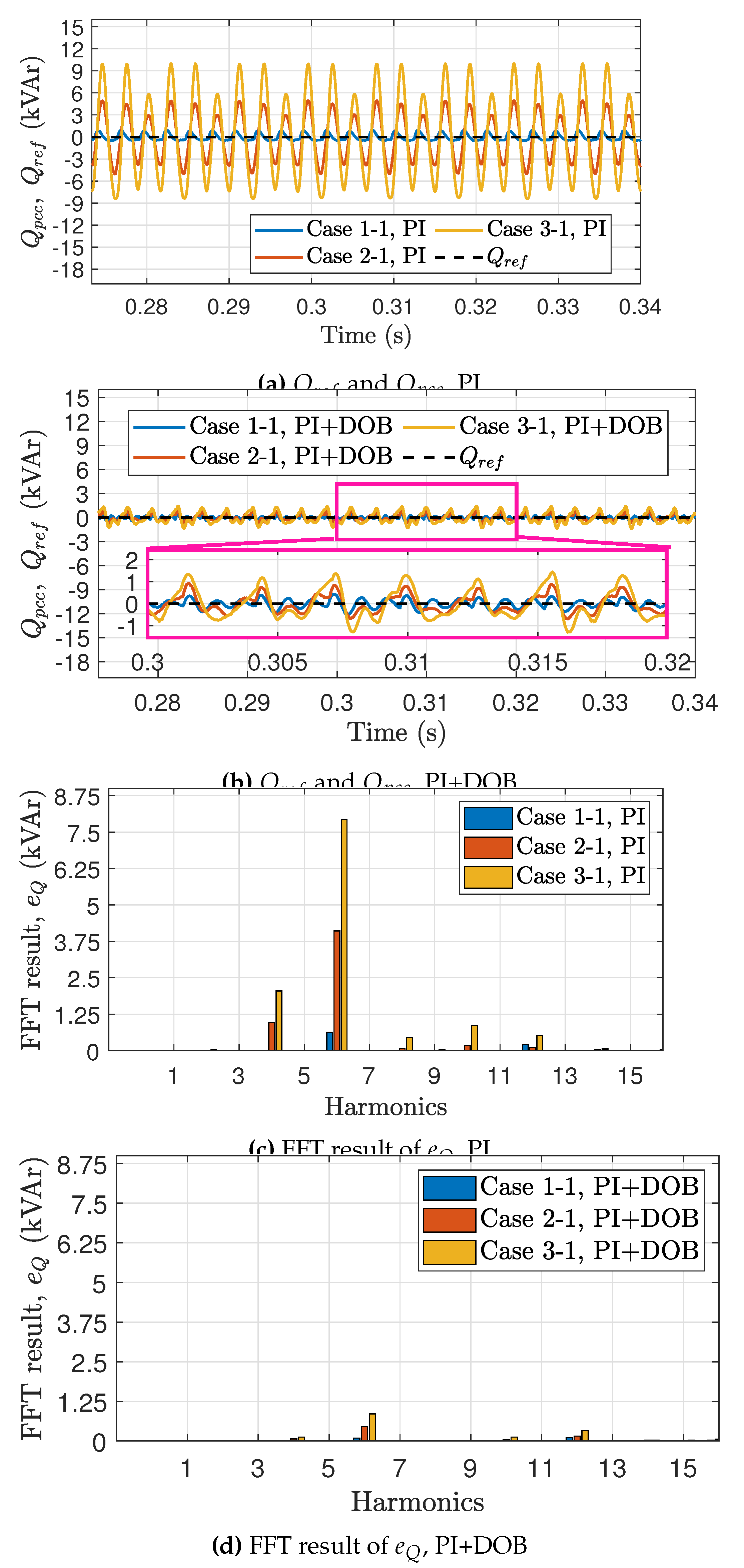
Figure 6 shows the comparative studies of the active power control performance between PCCVM-DPC with PI and PCCVM-DPC with PI+DOB. Figure 6a and Figure 6b show the time plot of active power control performance for the PI and PI+DOB control structure, respectively. Figure 6c and Figure 6d shows the fast Fourier transform (FFT) results of the active power control performance, for the PI and PI+DOB control structure, respectively. As expected from the bode plot, we confirmed that the dramatic performance enhancement for the harmonic disturbances is achieved. Figure 7 shows the comparative studies of the reactive power control performance between PCCVM-DPC with PI and PCCVM-DPC with PI+DOB. Figure 7a and Figure 7b shows the time plot of reactive power control performance for the PI and PI+DOB control structure, respectively. Figure 7c and Figure 7d show the FFT results of the reactive power control performance, for the PI and PI+DOB control structure, respectively. As expected from the bode plot, we confirmed that the dramatic performance enhancement for the harmonic disturbances is achieved. Figure 8 shows the FFT results of the phase currents for each case. From these results, we see that the proposed PCCVM-DPC with PI+DOB dramatically reduces the current THD by more than 40% of the THD of the PI control structure.

4. Conclusions

This paper proposed the point of common connection voltage modulated direct power control (PCCVM-DPC) for energy storage systems and power conversion system (ESS/PCS) with the disturbance observer and disturbance rejection structure to control the instantaneous active and reactive powers under the step-up transformer’s nonlinearity, parametric uncertainties, and the grid voltages harmonics. From the validation with the Simscape and the actual ESS inverter and transformer datasheet, we observed that PCCVM-DPC with the proposed control structure has robust power control performance although the measured voltages at the PCC contain inadequate harmonics. The comparative studies between the PI control structure and the proposed control structure validated the outperformance of the proposed method.

Acknowledgments

This work was supported by the National Research Foundation of Korea (NRF) grant funded by the Korean government (MSIT) (No. RS-2023-00213640, Accurate Autonomous Tracking Control by Unmatched Disturbance Compensator with Reference Re-design Filter), the Industrial Source Technology Development Program(20018144, Development and PoC of Personal Mobility service robot platform) funded by the Ministry of Trade, Industry and Energy (MOTIE, Korea) and the Pukyong National University Industry-university Cooperation Foundation’s 2024 Post-Doc. support project.
The author appreciates Prof. Chung Choo Chung for pre-reviewing the proposed formulation and the simulation environments of this paper before submission.

References

  1. IRENA. Renewable Capacity Statistics 2024. International Renewable Energy Agency (IRENA).
  2. Solanke, T.U.; Ramachandaramurthy, V.K.; Yong, J.Y.; Pasupuleti, J.; Kasinathan, P.; Rajagopalan, A. A review of strategic charging–discharging control of grid-connected electric vehicles. Journal of Energy Storage 2020, 28, 101193. [CrossRef]
  3. Wu, D.; Ma, X. Modeling and optimization methods for controlling and sizing grid-connected energy storage: A review. Current Sustainable/Renewable Energy Reports 2021, 8, 123–130. [CrossRef]
  4. Zhao, C.; Andersen, P.B.; Træholt, C.; Hashemi, S. Grid-connected battery energy storage system: a review on application and integration. Renewable and Sustainable Energy Reviews 2023, 182, 113400. [CrossRef]
  5. Choudhury, S. Review of energy storage system technologies integration to microgrid: Types, control strategies, issues, and future prospects. Journal of Energy Storage 2022, 48, 103966. [CrossRef]
  6. Rahmani-Andebili, M. Stochastic, adaptive, and dynamic control of energy storage systems integrated with renewable energy sources for power loss minimization. Renewable Energy 2017, 113, 1462–1471. [CrossRef]
  7. Lee, K.; Venkataramanan, G.; Jahns, T.M. Modeling effects of voltage unbalances in industrial distribution systems with adjustable-speed drives. IEEE Transactions on Industry Applications 2008, 44, 1322–1332. [CrossRef]
  8. Campbell, M.; Arce, G. Effect of motor voltage unbalance on motor vibration: Test and evaluation. IEEE Transactions on Industry Applications 2017, 54, 905–911. [CrossRef]
  9. Gontijo, G.F.; Tricarico, T.C.; da Silva, L.F.; Krejci, D.; França, B.W.; Aredes, M.; Guerrero, J.M. Modeling, control, and experimental verification of a DFIG with a series-grid-side converter with voltage sag, unbalance, and distortion compensation capabilities. IEEE Transactions on Industry Applications 2019, 56, 584–600. [CrossRef]
  10. Lu, D.; Wang, X.; Blaabjerg, F. Impedance-based analysis of DC-link voltage dynamics in voltage-source converters. IEEE Transactions on Power Electronics 2018, 34, 3973–3985. [CrossRef]
  11. Zeng, Q.; Chang, L.; Song, P. SVPWM-based current controller with grid harmonic compensation for three-phase grid-connected VSI. 2004 IEEE 35th Annual Power Electronics Specialists Conference (IEEE Cat. No. 04CH37551). IEEE, 2004, Vol. 4, pp. 2494–2500.
  12. Hadjidemetriou, L.; Kyriakides, E.; Blaabjerg, F. A grid side converter current controller for accurate current injection under normal and fault ride through operation. IECON 2013-39th Annual Conference of the IEEE Industrial Electronics Society. IEEE, 2013, pp. 1454–1459.
  13. Blaabjerg, F.; Teodorescu, R.; Liserre, M.; Timbus, A.V. Overview of control and grid synchronization for distributed power generation systems. IEEE Transactions on Industrial Electronics 2006, 53, 1398–1409. [CrossRef]
  14. Wang, X.; Harnefors, L.; Blaabjerg, F. Unified impedance model of grid-connected voltage-source converters. IEEE Transactions on Power Electronics 2017, 33, 1775–1787. [CrossRef]
  15. Kaura, V.; Blasko, V. Operation of a phase locked loop system under distorted utility conditions. IEEE Transactions on Industry Applications 1997, 33, 58–63. [CrossRef]
  16. Chung, S.K. A phase tracking system for three phase utility interface inverters. IEEE Transactions on Power Electronics 2000, 15, 431–438. [CrossRef]
  17. Rodríguez, P.; Luna, A.; Candela, I.; Mujal, R.; Teodorescu, R.; Blaabjerg, F. Multiresonant frequency-locked loop for grid synchronization of power converters under distorted grid conditions. IEEE Transactions on Industrial Electronics 2010, 58, 127–138. [CrossRef]
  18. Wen, B.; Boroyevich, D.; Burgos, R.; Mattavelli, P.; Shen, Z. Analysis of D-Q small-signal impedance of grid-tied inverters. IEEE Transactions on Power Electronics 2015, 31, 675–687. [CrossRef]
  19. Zhou, J.Z.; Ding, H.; Fan, S.; Zhang, Y.; Gole, A.M. Impact of Short-Circuit Ratio and Phase-Locked-Loop Parameters on the Small-Signal Behavior of a VSC-HVDC Converter. IEEE Transactions on Power Delivery 2014, 29, 2287–2296. [CrossRef]
  20. Kazmierkowski, M.P.; Malesani, L. Current control techniques for three-phase voltage-source PWM converters: A survey. IEEE Transactions on Industrial Electronics 1998, 45, 691–703. [CrossRef]
  21. Reyes, M.; Rodriguez, P.; Vazquez, S.; Luna, A.; Teodorescu, R.; Carrasco, J.M. Enhanced decoupled double synchronous reference frame current controller for unbalanced grid-voltage conditions. IEEE Transactions on Power Electronics 2012, 27, 3934–3943. [CrossRef]
  22. Errouissi, R.; Shareef, H.; Awwad, F. Disturbance observer-based control for three-phase grid-tied inverter with LCL filter. IEEE Transactions on Industry Applications 2021, 57, 5411–5424. [CrossRef]
  23. Gui, Y.; Kim, C.; Chung, C.C. Grid voltage modulated direct power control for grid connected voltage source inverters. 2017 American Control Conference (ACC). IEEE, 2017, pp. 2078–2084.
  24. Gui, Y.; Wang, X.; Blåbjerg, F.; Pan, D. Control of grid-connected voltage-source converters: The relationship between direct-power control and vector-current control. IEEE Industrial Electronics Magazine 2019, 13, 31–40. [CrossRef]
  25. Gao, S.; Zhao, H.; Wang, P.; Gui, Y.; Terzija, V.; Blaabjerg, F. Comparative Study of Symmetrical Controlled Grid-Connected Inverters. IEEE Transactions on Power Electronics 2022, 37, 3954–3968. [CrossRef]
  26. Gui, Y.; Kim, C.; Chung, C.C.; Guerrero, J.M.; Guan, Y.; Vasquez, J.C. Improved direct power control for grid-connected voltage source converters. IEEE Transactions on Industrial Electronics 2018, 65, 8041–8051. [CrossRef]
  27. Zhang, Z.; Wang, P.; Jiang, P.; Gao, F.; Fu, L.; Liu, Z. Robust Control Method of Grid-Connected Inverters With Enhanced Current Quality While Connected to a Weak Power Grid. IEEE Transactions on Power Electronics 2022, 37, 7263–7274. [CrossRef]
  28. Chowdhury, V.R.; Kimball, J.W. Robust Control Scheme for a Three Phase Grid-Tied Inverter With LCL Filter During Sensor Failures. IEEE Transactions on Industrial Electronics 2021, 68, 8253–8264. [CrossRef]
  29. Hollweg, G.V.; de Oliveira Evald, P.J.D.; Tambara, R.V.; Gründling, H.A. A robust adaptive super-twisting sliding mode controller applied on grid-tied power converter with an LCL filter. Control Engineering Practice 2022, 122, 105104. [CrossRef]
  30. Ma, Y.; Yang, L.; Zhou, X.; Yang, X. Second-Order Linear Active Disturbance Rejection Control and Stability Analysis of Energy Storage Grid-Connected Inverter. IEEE Access 2020, 8, 160738–160748. [CrossRef]
  31. Xie, Z.; Chen, Y.; Wu, W.; Gong, W.; Zhou, L.; Zhou, X.; Guerrero, J.M. Admittance Modeling and Stability Analysis of Grid-Connected Inverter With LADRC-PLL. IEEE Transactions on Industrial Electronics 2021, 68, 12272–12284. [CrossRef]
  32. LS ELECTRIC Co., L. Modular Scalable PCS Catalog. Updated: 2022-Jul-14.
  33. LS ELECTRIC Co., L. Cast Resin Transformer Catalog. Updated: 2024-Aug-20.
  34. IEC 60076-11:2018. Power transformers - Part 11: Dry-type transformers. IEC 60076-11:2018 2018.
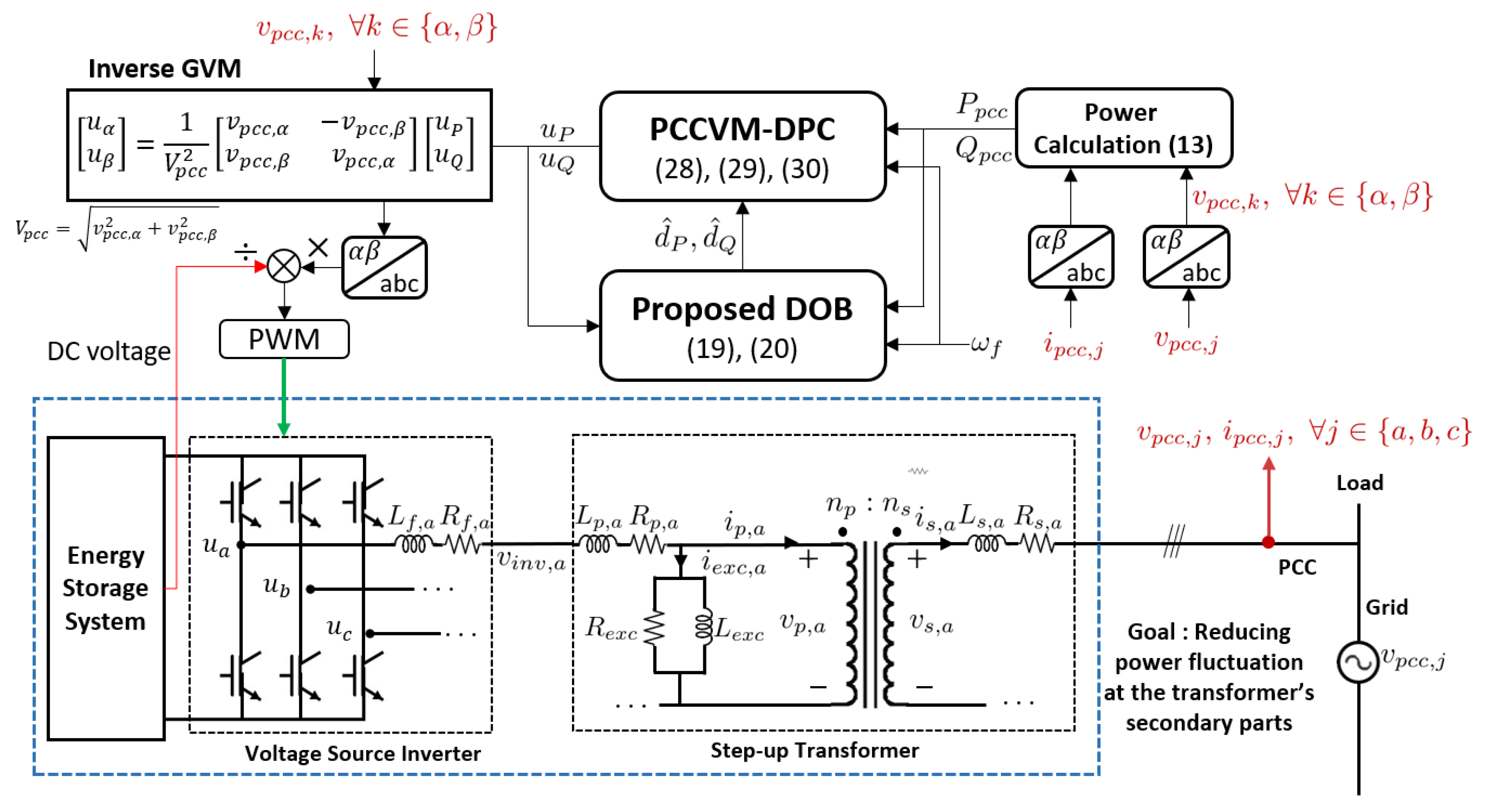
Figure 1. Schematic of the grid-connected voltage source inverter with the step-up transformer and the proposed PCCVM-DPC and proposed DOB.
Preprints 117496 g001
Figure 4. Fast Fourier Transform (FFT) result of v p c c , a
Preprints 117496 g004
Figure 5. Validation results of the estimated disturbances of PI+DOB in the case of the DC voltage is 1000 V.
Preprints 117496 g005
Figure 6. Validation results of the active power for PCCVM-DPC with PI and PI+DOB in the case of that the DC voltage is 1000 V.
Preprints 117496 g006
Figure 7. Validation results of the reactive power for PCCVM-DPC with PI and PI+DOB in the case of that the DC voltage is 1000 V.
Preprints 117496 g007
Figure 8. Validation results of the current harmonics for PCCVM-DPC with PI and PI+DOB in the case of that the DC voltage is 1000 V.
Preprints 117496 g008
Table 1. Parameters used in simulation [32,33,34]
Param Value Unit Param Value Unit
T s 100 ns f c t r l 20 k H z
f p w m 10 k H z t d 6 μ s
f 0 60 Hz V d c 1000 V
L f 6.00 mH R f 0.15 Ω
L p 91.7 μ H R p 2.7 m Ω
L s 0.33 H R s 9.63 Ω
L e x c 663.15 H R e x c 1.851 M Ω
V p , j 380 V V s , j 22.9 kV
k p 5277.9 - k i 6.940e6 -
l p 1.508e4 - l i 5.685e7 -
Disclaimer/Publisher’s Note: The statements, opinions and data contained in all publications are solely those of the individual author(s) and contributor(s) and not of MDPI and/or the editor(s). MDPI and/or the editor(s) disclaim responsibility for any injury to people or property resulting from any ideas, methods, instructions or products referred to in the content.
Copyright: This open access article is published under a Creative Commons CC BY 4.0 license, which permit the free download, distribution, and reuse, provided that the author and preprint are cited in any reuse.
Prerpints.org logo

Preprints.org is a free preprint server supported by MDPI in Basel, Switzerland.

Subscribe

© 2024 MDPI (Basel, Switzerland) unless otherwise stated