1. Introduction
There are many application scenarios of Wireless Sensor Networks (WSNs), such as environmental detection, civil infrastructure, target tracking, information security, and intelligent media care [
1,
2]. In WSNs, energy replenishment is becoming the bottleneck to improve network utility. Currently, most sensor nodes are powered by batteries. However, the high manufacturing and swapping cost of batteries hinder WSNs from fully realizing their potential. Wireless charging is one of the most promising technologies for tackling the energy limitation problem of sensor nodes. With the assistance of a wireless charger, the sensor node can prolong its lifetime without replacing batteries. The functionality of the sensor node includes sensing, computing, data collection, and data aggregation [
3,
4]. In addition, the sensor node uploads data to the sink node in real time and accepts the control instructions from the cloud server via a wireless communication module. Since a large amount of information will be processed and transmitted by sensor nodes, the energy of RWSNs will gradually decrease with time [
5]. Once the battery energy has been exhausted and cannot be replenished [
6], it will lead to the death of the sensor nodes. Therefore, the energy consumption of sensor nodes becomes a prominent issue and is regarded as a main factor of large-scale application in RWSNs. To effectively extend the lifetime of RWSNs, the scheduling strategies of sensor nodes are proposed to improve energy utilization. Most rechargeable batteries are non-removable, and the sensor nodes will die due to battery energy depletion.
Recent studies [
7,
8] have proposed using mobile chargers to transmit wireless charging power to sensor nodes [
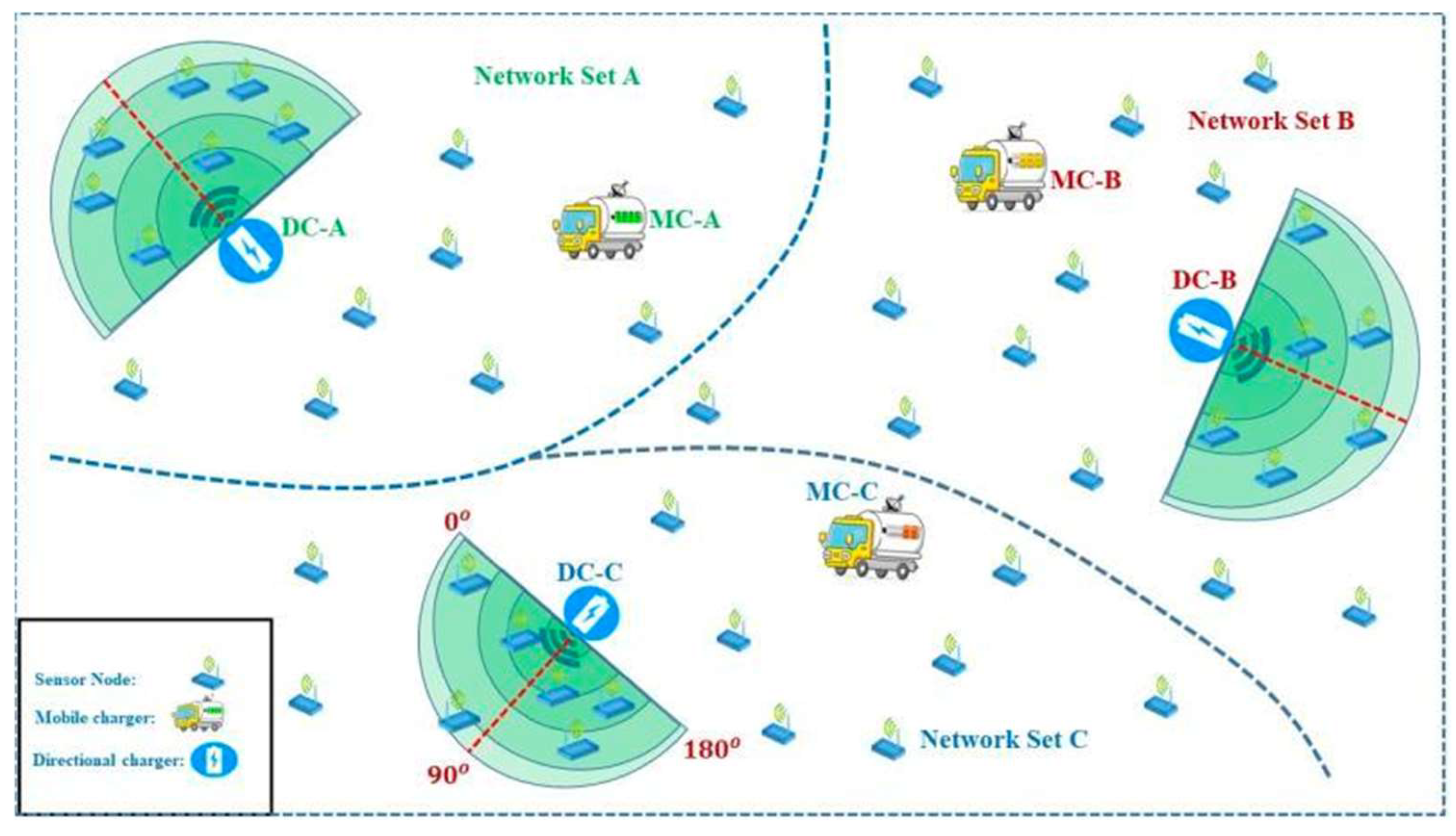
9]. The weakness of previous studies is that mobile chargers cannot transmit proper energy because mobile chargers have limited battery capacity and select limited routing paths to transmit charging power to the area of RWSNs. Different sensor node cannot maintain their working power due to the limited energy. In our proposed research, a mobile charger and a directional charger have been used jointly to transmit wireless charging power to each sensor node to overcome these challenges. To the best of our research, we transmit maximum energy to sense maximum data from the maximum sensor node. The predetermined recharging scheduling of mobile chargers provides a near-optimal charging path due to the dynamic energy consumption. In RWSNs, a directional charger transmits energy to the sensor node from different orientations. In RWSNs, each directional charger selects its total 180o area, and each orientation covers 90o area to fulfill the energy demand of each sensor node. Directional chargers cover the network area in two directions; each orientation covers 90 areas. Mobile charger covers those nodes that are out of the coverage area of directional chargers. The critical challenge of our designed research is the coupling of directional chargers and mobile chargers to fulfill the energy demand without delay.
In our proposed research, the Mix Integral Programming Method has been used to find the optimal stopping point of mobile chargers. After selecting the optimal stopping point, the mobile and directional chargers jointly start energy transmission. At each time slot, the mobile and directional chargers select their number of sensor nodes for energy transmission. We must transmit maximum energy at each time slot to overcome the joint energy replenishment challenge. In RWSNs, a time slot-based algorithm has been used for energy transmission to each node in our proposed research. The joint charging process is used to transmit energy to each set of networks. We used a priority-based charging method. In this optimal algorithm, when the node has less residual energy, the priority of energy supplement is higher and should be replenishment with higher charging priority. After that, we select the tour length of the mobile charger for maximum energy transmission. Some nodes far from mobile charger tours cannot replenish energy properly. These sensor nodes will be charged in the next tour. In this algorithm, we need to bind the length of the mobile charger tour to transmit maximum energy within each time slot. Moreover, we used an optimal joint-based charging algorithm to charge sensor nodes jointly with the help of a mobile charger and a directional charger.
This research aims to optimize the data transmission rate while preserving charging delay. If we only use DC for energy transmission in RWSNs, then only DC cannot satisfy all the charging demands of each node due to a fair charging delay. To tackle this issue, we need to schedule the MC and DC jointly to fulfill the charging demand of each node. MC starts the route from the base station, and after transmitting energy to different sensor nodes, it returns to the base station for energy replenishment.
The main contribution of this paper can be summarized as follows.
To the best of our knowledge, this is the first work to study the joint scheduling problem of DC and MC for energy replenishment. We noticed that the throughput of WRSNs can be further improved by jointly working on the performance of the MC and DC.
We designed a near-optimal joint energy replenishment algorithm and proposed a central charging point selection algorithm for proper energy transmission.
Extensive simulation results are conducted to indicate the effectiveness and advantages of our proposed algorithms.
The organization of this paper is shown as follows. Section II describes the related work. Section III contains the Methodology. Section IV presents the network model. Section V is the Charging Model, and Section VI presents the problem formulation. Section VII is the Mobile Charging Energy Transmission Protocol. Section VIII is the Evaluation along with the simulation results of the proposed scheme, which are compared with those of the other schemes. Section IX shows the conclusion of this paper with a brief summary of new findings.
2. Related Work
Different existing research has focused on energy harvesting techniques that extract energy from solar, vibration, and wind to replenish energy in sensor nodes. A new way of supplying high-density, stable, and sustainable energy for sensor nodes is provided by wireless energy transfer technology. Recently power cast has developed products that transmit energy to the sensor nodes [
10]. In [
11], constructing a charging queue based on the greedy algorithm, the author used power cast chargers to extend the network lifetime.
2.1. Mobile Charging Scheduling
For replenishing energy to each sensor node through strong magnetic resonance, there has been a surge of interest in using the MC traveling algorithms in WRSNs [
12]. Most of the reported approaches employed optimization algorithms to solve wireless charging problems. A single mobile charger can charge sufficiently to a small-scale network of RWSNs. Due to the limitation of battery capacity of the sensor nodes, multiple mobile chargers are required for large-scale areas of a network. Energy replenishment provides stability and reliability of energy supply for sensor nodes [
13]. The mobile charging energy transmission process can be evaluated from the sensor node’s and charger’s perspective [
13]. The most intuitive way is to charge sensor nodes periodically along an optimal TSP tour in RWSNs [
8].
The researcher employed a mobile charger to charge sensor nodes, where the cumulative traveling time and charging time are expected to be minimized. The best charging scheme was reported [
13], which jointly considers routing and charging. In a dynamic environment, the objective is to maximize network lifetime under practical constraints. In [
14], proposed multiple energy-constrained mobile charging scheme to charge RWSNs collaboratively. The objective is to maximize the energy efficiency of sensor nodes. In [
8,
15] focused on a charging strategy that employed a mobile charger equipped with a high-capacity battery to replenish energy periodically in sensor nodes. In [
16], the problem into 2-D WSNs and the minimum number of energies-constrained mobile chargers. The aim of this work is to guarantee the performance of the network. The average performance is far from an optimal charger. In [
17], investigated the problem of minimizing the number of mobile chargers to ensure that each sensor node operates continuously for energy transmission. With the different charging cycles of MC, the results of the charging tour are different. In [
18], considered multiple mobile chargers to minimize the total traveling cast of MC to ensure that each node replenishes energy from the sensor node. In [
19] modeled on-demand charging scheme as scheduling MC vehicles deployed to charge sensor nodes. The objective is to minimize the number of mobile chargers.
In [
20], the scheduling for the multiple MCs for incoming charging requests to evaluate the nearest-first and recent-rarest-first strategies. As a result, the nearest scheduling strategy is better for the localization charging request process, which is made through simulation. In [
18], the node energy level cannot become low from its maintaining level. Multiple MCs minimize the total traveling cost of multiple mobile chargers. In [
19], mobile chargers return to their respective depots for energy replenishment. To charge sensor nodes in WRSNs, the network model works on-demand charging problems as per the schedule of a mobile charger. The objective is to minimize the number of mobile charger routes for maximum energy transmission.
2.2. Directional Charging Scheduling
Some works are studying on directional charger problem, but their solutions are not applied in our research. In [
21], proposed a method to detect omnidirectional charging capability for a given topology of directional chargers. They also studied how to place directional chargers to maximize charging utility in [
22]. To resolve the wireless charger deployment optimization problem. In [
23], deployed the chargers with directional antennas on specific grid points and designed the greedy and adaptive cone covering algorithms. To maximize the survival rate of end devices an omnidirectional wireless charger with partial coverage has been used to maximize the survival rate of terminal devices [
24].
One of the importance of directional antenna is to transmit maximum energy in different directions to cover different sensor nodes in one sector. However, these models are so complicated that they are not tractable in the performance analysis. Using directional antennas instead of omnidirectional antennas in wireless ad hoc networks or RWSNs can significantly improve the network performance since directional antennas can concentrate the transmitting/receiving capability to desired directions [
25].
Figure 1 shows the WRSN. For example, it is shown in some recent studies that using directional antennas in WANs can improve the network capacity and reduce the end-to-end delay [
26,
27,
28,
29]. Besides, using directional antennas in WSNs can improve security, as shown in [
25,
30]. In WSNs with directional antennas, it is difficult for each node to obtain the location knowledge of other neighbors due to the directional beam forming [
31]. To solve the problem of directional neighbor discovery, complicated schemes, such as using direction of arrival estimation, and swiveling the beam from 0 to 2π, were proposed in [
32].
To best of our knowledge, this is the first work to study the mobile charger and directional charger problem in RWSNs. The existing works have contributed to optimizing the power supply through the mobile charger and directional charger. However, coupling issue in mobile chargers and directional chargers makes the rechargeable wireless sensor network charging problem quite challenging. Previous works did not consider the joint charging method using by mobile charger and directional charger jointly to transmit maximum energy and minimum charging delay. The novelty of our proposed research is that there is no data loss in our proposed work because of on-demand energy transmission to each sensor node.
3. Methodology
The critical challenge of our design is the coupling of DC and MC used to fulfill the energy demand without delay. In RWSNs, each DC selects its total area, with each specific orientation to fulfill the energy demand of each node in every time slot. MC selects a network area that is out of the coverage area of DC. The charging process with the MC antenna is highly gain, which is used for energy transmission in each set of networks. MC selects the optimal stopping point in each set of networks to charge all sensor nodes at different time slots. After selecting a specific network area, MC and DC jointly start energy transmission to each sensor node. At each time slot, MC and DC select a different number of sensor nodes for energy transmission. MC travels from the base station to each charging point, obtained by solving Mix Integral Programming. When the energy level of MC is low, it returns to the base station for energy replenishment.
We need to choose different MC stopping points from each set of sensor nodes from each set of networks. After selecting a specific area by MC and DC, both chargers jointly start energy transmission to the sensor node. At different times slot MC turns its antenna orientation toward the area of DC to transmit maximum energy. To overcome the joint energy replenishment challenge, we need to transmit maximum energy to each sensor node at each time slot to collect maximum data from each node. It is quite hard to utilize the limited energy of DC and MC to charge the lowest energy demand sensor node and maintain the network performance continuously. For energy transmission to each set, MC selects its route from the base station. MC finds the optimal stop location in each set of sensor nodes with the help of Mix Integral Programming. In RWSNs, after finding the optimal location, MC starts to replenish charging power to each node that is out of the coverage area of DC and in the coverage area of DC.
Voronoi diagram has been used to divide the network area into different sets. In RWSNs, we must allocate a time slot-based algorithm for energy transmission to each node. The joint charging process is usually used to transmit energy in each set of networks. For proper energy transmission to each node, we select the tour length of MC. We bound the length of the MC tour to maintain network operation. The proposed work’s objective is to increase each node’s sensing rate.
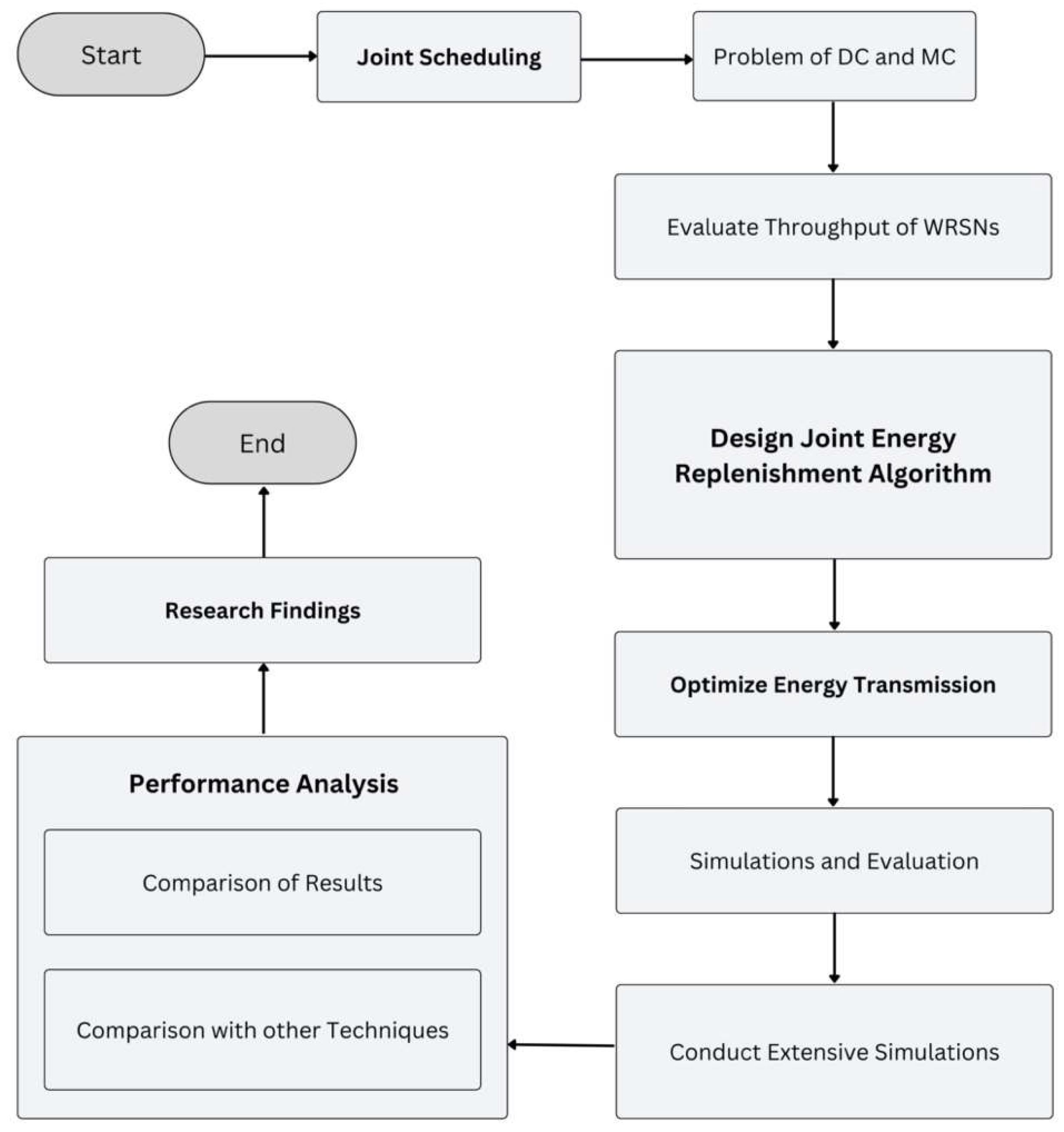
In our proposed research, simulation is built in the widely used MATLAB. Experiment results show our proposed algorithm works efficiently to obtain maximum throughput. The main contribution of this paper can be summarized as follows. To the best of our knowledge, this is the first work to study the joint scheduling problem of DC and MC for energy replenishment. We noticed that the throughput of WRSNs can be further improved by jointly working on the performance of the MC and DC. We design a near-optimal joint energy replenishment algorithm and propose a central charging point selection algorithm for proper energy transmission. Extensive simulation results are conducted to indicate the effectiveness and advantages of our algorithms.
Figure 2 shows the methodology of the research work.
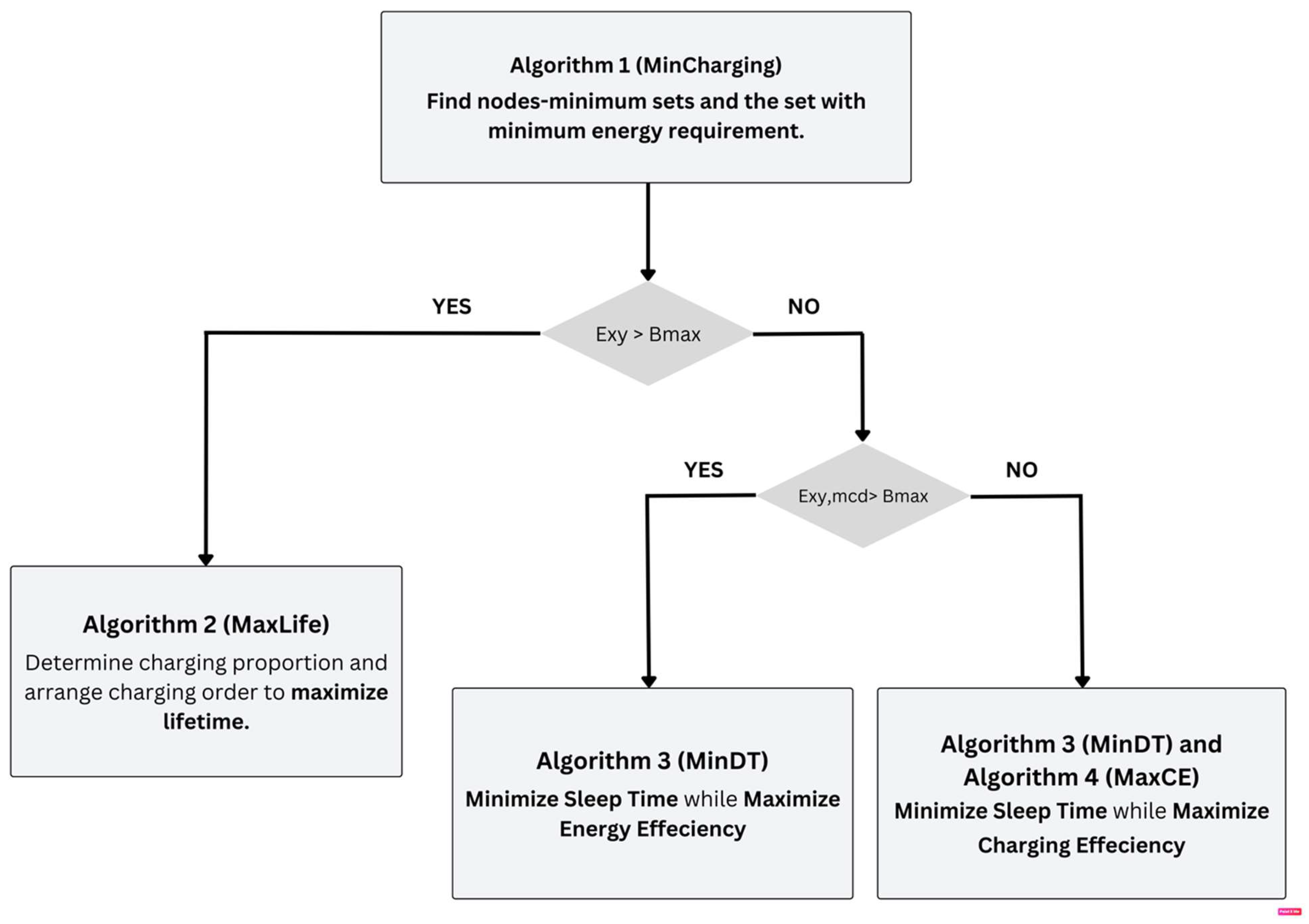
This flowchart contains a multi-step algorithmic methodology to increase power consumption and charging productivity. It starts with the first algorithm (Min-Charging), which distinguishes the arrangement of nodes with the required minimum energy assumption. Depending on whether the energy condition (E XY exceeds the most extreme limit of the battery (B maximum, the cycle process into different paths. It is unlikely that E XY is more remarkable than the calculation of B maximum) second algorithm (MaxLife) is used to decide on charging, the cycle checks if E XY, MCD exceeds B maximum Assuming it does, Algorithm 3 (MinDT) is used to limit rest time and increase energy productivity the extra chance that E XY, MCD is not exactly B maximum , both calculation in algorithm 3 (MinDT) and algorithm 4 (MaxCE) are used to limit the rest time and expand the charging efficiency This organized methodology expects to improve the total energy of the system and the functionality efficiency in overall system.
Figure 3 shows the framework of the algorithms.
4. Network Model
In RWSNs, it should be desirable that all sensor nodes should be charged before its energy depletion. To achieve this goal, we need to transmit maximum charging power to maximum sensor node at each time slot. In RWSNs, a set of rechargeable sensor node , a set of sink station and a set of directional chargers are deployed randomly at different position. Where each sensor node senses data and transmits data to sink node. In RWSNs, we jointly used MC and DC to transmit maximum energy to maximum sensor node as per energy demand.
After replenishing energy from the basic station MC select its shortest routing path to charge sensor nodes which are out of coverage of DC as well as under the coverage of MC. At different time slot, MC turn their route towards directional charger coverage area and transmit energy to the different sensor nodes which are in the coverage area of DC to maintain the energy level of each node. So in our propose scheme we need to schedule the routing path of mobile charge to covers sensor nodes which are out of coverage area of DC as well as which is under the coverage area of directional charger.
In this research, we apply a tree topology with fixed routing path, where each sensor node has only single link to next hop. One bit of data is sensed by node and transmit to sink station through a fixed routing table. In this research, we divide nodes into different sets. In RWSNs, we need to schedule the MC to transmit maximum energy to each sensor node.
We divide time series of directional charger into different slots each time slot, DC changes its each orientation from two orientations with to transmit charging power to the different no node in the area of network. At each two orientation, directional charger covers different number of nodes with angle. DC covers each two orientations with angle to increase coverage length of nodes for energy transmission. The total coverage area of DC is angle. MC covers remaining angle area which is uncovered by the DC.
In RWSNs, each node have different energy consumption rate at different time. We need to select optimal stoping point of MC from each set of sensor nodes to transmit maximum charging power to maximum sensor nodes. The objective of this research is to maximize network lifetime with the help of maximum energy transmission. Thus we apply the following model for optimization.
Eq. 1 shows the sensing rate of node , Eq. 2 shows the data conservation constraint. For each sensor node, the aggregated incoming data flow equal to the aggregated data outgoing flow. Eq. 3 calculates the available charging power of every sensor node. Eq. 4 is the power which shows that the consumption charging power should never exceed the total charging power. Eq. 5 shows the sensor node coverage area in the network area where MC transmits charging power at the node.
Table 1.
Notation Description.
Table 1.
Notation Description.
| Symbol |
Defination |
|
sensing rate of node |
|
number of nodes which are deployed in the area of network |
|
number of chargers which are deployed in the area of network |
|
data inflow in node |
|
data outflow of node |
|
denote wither node is in charger coverage area |
|
parameter energy consumption for node to sense one bit of data |
|
parameter energy consumption for node to receive one bit of data |
|
parameter energy consumption for node to transmit one bit of data |
|
charging power that comes from charger to node |
|
node coverage area where mobile charger provide energy at each super node |
|
relationship between mobile charger and super node |
|
is the first super node where mobile charger transmit energy to super node |
|
position of the node where mobile charger provide energy to the node |
5. Charging Model
Our design is based on the power cast wireless charging and sensing platform> we utilize the friis space equation, which has been experimentally proved to be a good approximation of the energy recharging and commonly applied, to represent the energy recharging model in Eq. 6. We claim that our design can work on any energy-recharging model, whose charging power is monotone and increase with the distance betwwen charger and sensor node.
Where
is is the Euclidean distance between the charger and sensor node.
is the source power.
is the source antenna gain.
is the receive antenna gain.
is the polarization loss.
is a parameter to adjust the model for short-distance transmission.
is the wavelength
is the parameter to set the rectifier efficiency. For easy presentation, we simplify the energy charging model as shown in Eq. 7.
6. Problem Formulation
In our proposed scheme for WRSNs, for proper energy transmission to each sensor node, first we divide the network area into different sets. With the help of different sets, we can transmit maximum energy to each sensor node. We use a Voronoi-based algorithm to divide the network area into different sets. In each set of the network one DC and MC are used to transmit energy to the different sensor nodes in RWSNs. The process of charging with a mobile charger is highly gained. We can combine nodes within different sets then all nodes in the coverage of DC and out of DC coverage area in can be charged at different time slots.
6.1. Time Slot-Based Charging
The proposed charging algorithm jointly works with directional and mobile chargers. The schedule of directional chargers and mobile chargers is identical and the charging activities of each set of nodes are repeated at different times. Due to the time-varying nature of energy demand, we divide the time for joint energy transmission in each node into fixed time intervals with length L. MC contains multiple slots for energy transmission. In each time slot, MC run a tour to selectively recharge sensor nodes from low energy levels. Energy transmission of one node should be finished before the current slot ends. To assure the next node energy transmission can be timely started in the next period. In the network area, sensor nodes as well as DC consume energy at different rates. We need to divide the time for energy transmission according to slot length. MC and DC jointly recharge sensor nodes to maintain the energy level of each node. A slot is the smallest time unit where one charger can replenish energy to each node. In the network area, MC is responsible for energy transmission at each set of network areas. In each set of networks, time is divided for different sensor nodes as well as directional chargers. Each set has one DC which covers sensor nodes. At each time slot, the MC antenna changes its orientation to select a node for energy transmission.
The length of slot is which is the duration of each node for energy transmission. They required charging period of each node is based on slot length. The cycle length L is the required charging period of all sensors in each set of networks. The duration of the charging period of each node can be counted in term of the slot. Suppose the sensor is categorize into the number of in set. The required charging period of each set is in each slot.
with each node set and slot-based design. We can periodically schedule the power replenishment into slots based on the node-set. According to the schedule, in each period MC selectively charge a set of noes. We can give slots based on periodical charging. We first obtain nodes which have equal energy demand and then finally get recharging nodes as they have low data sensing rates because of low levels of energy. The charging tasks are issued in different slots at each time. A slot is called a working slot once there charging task issued in slot. The purpose of this algorithm is to obtain all working slots in one stopping point of MC.
6.2. Optimal Stopping Point with Mix Integral Programming
In a rechargeable wireless sensor network, the feasible region is the region where all constraints are satisfied. Pseudo- code for feasible region is as is the base station in RWSNs area. is the radius is the number of nodes in one set of network area. Assume all nodes use power Now the idea is interesting to narrow down the continuous stop of charger in each set of network area, target node to be located by the circle where charger randomly stops at position destination by , . Let is the euclidian distance. is the time for node charge when charger stops at position then if then using all feasible regions remains as convex polygons. The optimal point or optimal location of mobile charger accurse at the corner point of the feasible region normally.
We define the feasible region as
is the energy available at source
is the energy available at destination
as
energy distribution from source node
to destination
is the energy loss from source node
to destination
Here we can write the problem mathematically using mixed integral programming as shown in Eq. 8, 9, 10 and 11.
Now consider the pair of nodes
and
as the targeted node and base node with feasible regions with
and
in each set of networks. Let the charger stop at
then the Eq. 12, 13 are as follows
and Eq 14, and 15 are
7. Mobile Charging Energy Transmission Protocol
The process of charging with a mobile charger antenna is highly gain which is usually used to transmit energy. We can combine nodes within different set and each set have a directional charger. When MC stop at the centre of then all nodes and one directional charger in area can be charged at different time slots. There are different nodes and one DC in each set of network coverage area which is covered by the mobile charger. The real number of networks cannot be larger then .
is the region and can be obtained from one set of network area that where is the shortest distance between MC and DC. The charging angle for MC to cover the set of nodes and DC. In area, to satisfy DC with charging power, we assign the maximum power consumption rate of all nodes as well as DC in area that is
To ensure the maximum number of nodes and DC to meet the relation in which is the charging power and is the average power consumption in all DC nodes and coverage area. We set the average charging time of the mobile charger to ensure the total charging power is greater than or equal to the energy depletion rate of all sensor nodes and DC, that is . By setting of and performing transposition, we get . Due to the existence of mobile charger moving time , it would lead to . As long exist, even very small, the relation can be obtain as , that is .
We define the MC charging coverage utility at stop on MC charging orientation as the sum of received power of the charging.
denotes the coverage area which is covered at the one-stop of MC in any MC antenna orientation
. MC stopping point
in charging orientation
and MC stop at the
point and find optimal antenna orientation
. The maximum charging utility at one stopping point is shown in Eq. 16.
here
denotes the coverage area which is covered at the one stop of MC in any MC antenna orientation
. From different nodes, we get the link
we have to choose different stop of the mobile charger. We have to choose different stop of mobile charger
to connect node for data transmission and their corresponding charging direction, where
.
is the possible MC direction to transmit energy to different nodes. We use
to denote the maximum coverage area of the network with the help of MC from one stopping point of MC, shown in Eq 17, 18 and 19.
There is a different orientation of MC change to transmit energy to the different sensor nodes. We can calculate the possible coverage utilities at with one point of MC.
7.1. Algorithm for Length Constrained of Mobile Charger
In this section, we select the tour length of MC for energy transmission. MC charge all nodes which is in the coverage area. Some nodes which are very far from the MC tour cannot find energy then MC selects these nodes in the second tour. So, we need to bind each MC tour to transmit maximum energy within a maximum time. In this section, first we select a close energy transmission tour
for a set of selected sensor nodes
to maximize the accumulative charging utility gain. Then we check the length
of the mobile charging tour. If yes, then
is a feasible energy transmission tour. A sensor node belonging to
with minimum ratio
will be removed,
as shown in Eq 20 and 21.
Assume a sensor node is removed from the MC charging tour and also charged in next charging tour. Two nodes are neighbour nodes in tour , and respectively. The existing two edges in . When node is removed then both edges will be also removed which connects node to node and a new edge is added in MC tour. The length of MC will be reduced. The node removal procedure continues until all nodes get proper energy from the MC.
7.2. Joint Base Algorithm
To tackle the problem, we propose the following solution. We design the joint-based algorithm for maximum energy transmission from DC and MC jointly to each sensor node. The only constraint comes from the limited energy that in each time slot, the total energy used by sensing and communication should never exceed the sum of remaining energy and charged energy. The consumed energy should be expressed as
Where
is the unit of energy of sensing and
. For each sensor node in state R, the total received energy can be expressed by.
where
The remaining energy after time
can be calculated as.
Thus, the battery capacity constraints is obtain
Maximum energy transmission can help to increase the sensing rate of each node. The selection of a node in each set with both chargers depends on the remaining energy to each node so we need to transmit maximum energy to each sensor node. At each time slot, after the selection of optimal charging point in set , the MC antenna selects the node for energy transmission. MC should be covered with a specific area of network but the remaining area of RWSNs should be covered by the DC. The angle of static DC should be decided by the energy demand of each node. At each time slot, each node requires different energy level. We set the score for each node in each iteration to evaluate its demand for being charged. Intuitively, the node with lower energy should have the charging priority. On the other hand, we adopt a tree-based routing protocol in our design. Then nodes in the upper layer should obtain more energy since they will take on more relay tasks.
Therefore, we design such scoring mechanism , where is related to the number of nodes layer (a closer node is in a top layer), denotes the remaining energy after the previous time slot, is the charging power that node has received in the current time slot, and is a factor to avoid the denominator being zero. Thus, in each time slot, we run the following mechanism to obtain MC and DC orientation scheduling. In each iteration, we update each node’s score, then we can calculate each sector’s total score, and we select the sector with highest score greedily. This process continues until every charger has decided on its covering sector. After the charger’s orientation has been decided, it is easy to obtain each node’s energy level in the current time slot. After that, we adopt the tree-based routing protocol to transmit data. In the area of the network, throughput is recorded, and the node’s energy is updated from time to time.
In a tree-based routing algorithm at each time slot, we need to check the data transmission rate to decide the energy transmission rate of each node. MC and DC jointly satisfy energy transmission. After that, the candidate’s next hope node with the smallest weight is selected as the actual next hope node during the process of considering the route and finding. The charging capability can be expressed as the energy level and the charging duration is equivalent to the size of the remaining energy and the charged energy. In the first layer, we consider nodes with low battery energy and high energy consumption as those dying nodes or more preciously, these nodes are more likely to die from exhaustion. In a network, the lower the residual energy is, the greater the energy consumption of the node.
8. Performance Evaluation
In this section, we describe the comprehensive simulation experiments to investigate the algorithm performance under different influence factors such as to sense maximum data as well as transmit data from each node. In the existing literature, no study focuses on MC and DC joint energy transmission in the network area. In this paper, all results are obtained from MATLAB.
8.1. Simulation Setting
We consider RWSNs, in which sensor nodes are equipped with the Powercast MC and DC charger and receivers employed. The sensor nodes are randomly deployed in a area and are used to monitor the environment and charge the sensor node. In RWSNs, different base stations are used to analyze the data from each set of network areas. In our proposed network area, we did experiments with different numbers of requested nodes in which charging planning is arranged. The entire charging protocol is evaluated in real-time on-demand scenarios.
In RWSNs, we use DC and MC jointly for maximum energy transmission. To assess the effectiveness of our proposed scheduling policies, we will now present the performance evaluation in RWSNs, which will be carried out using a discrete-evolution simulator. To evaluate the merits of our proposed algorithm, we run simulations to find the results of our proposed algorithm. To understand the performance of RWSNs, the joint energy transmission level of MC and DC should be changed at each time slot to check the performance of each node. We mainly focus on the validity of our proposed algorithm with joint energy transmission protocol. The MC routing path should be increased and decreased according to the energy demand of the sensor node. The sensing rate of each node is randomly chosen. Each sensor node has a different energy consumption rate. Each set of nodes is randomly chosen by MC. The corresponding information of the sensor node is generated and transmitted to the sink nodes.
In RWSNs, nodes send charging requests to DC and MC when their energy level is low. At each network set, MC records the energy request from each node, which is deployed in the DC coverage area as well as out of the coverage area of DC. The MC antenna changes its orientation at each time slot to transmit energy to RWSNs. The results show that DC transmits energy to each sensor node in the network area when sensor nodes send energy transmission requests. Recharging requests from each sensor node randomly arrived at chargers. MC selects its route to transmit energy to each sensor node. We use mixed integral programming to find the central point of MC to transmit maximum charging power to each sensor node
In
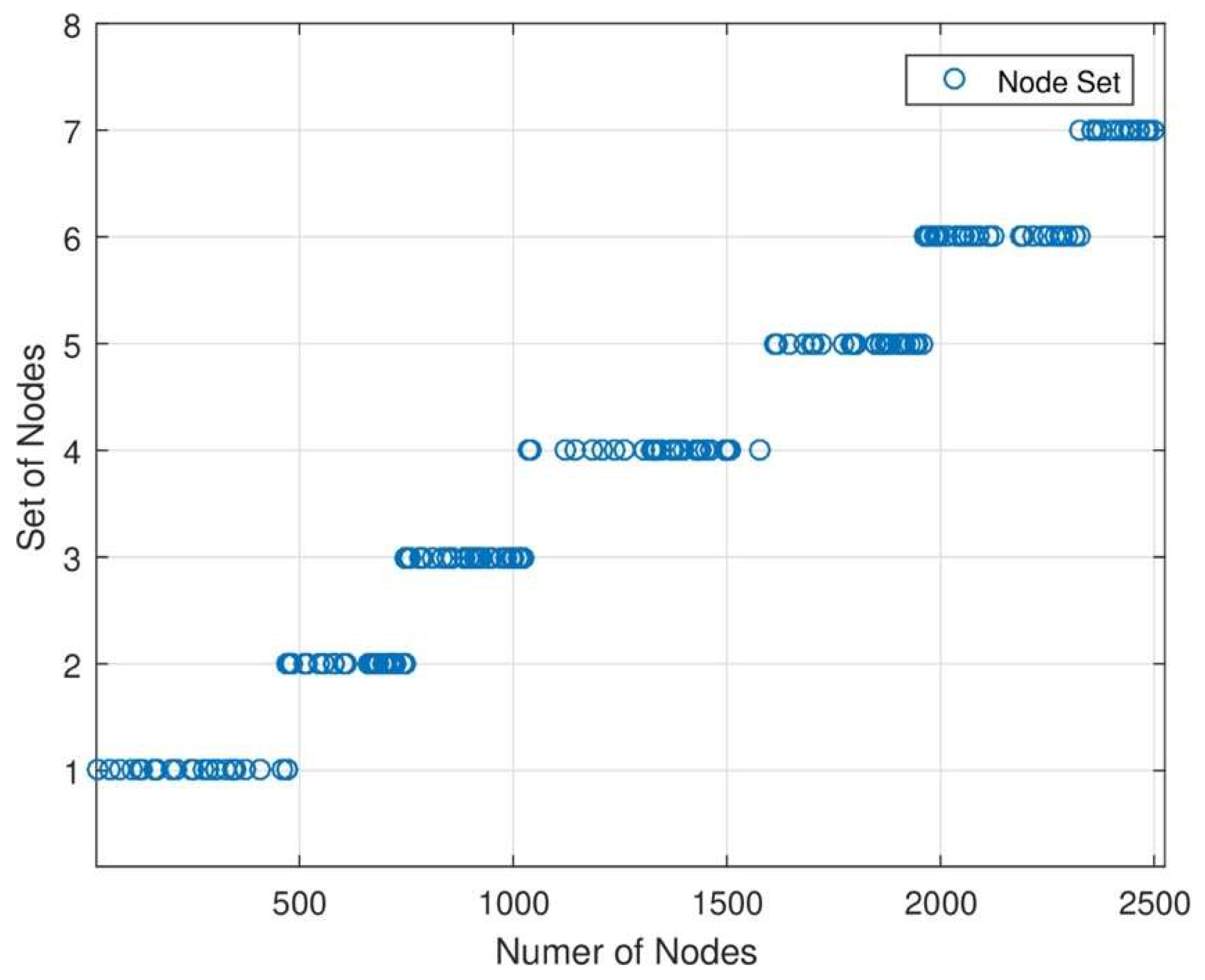
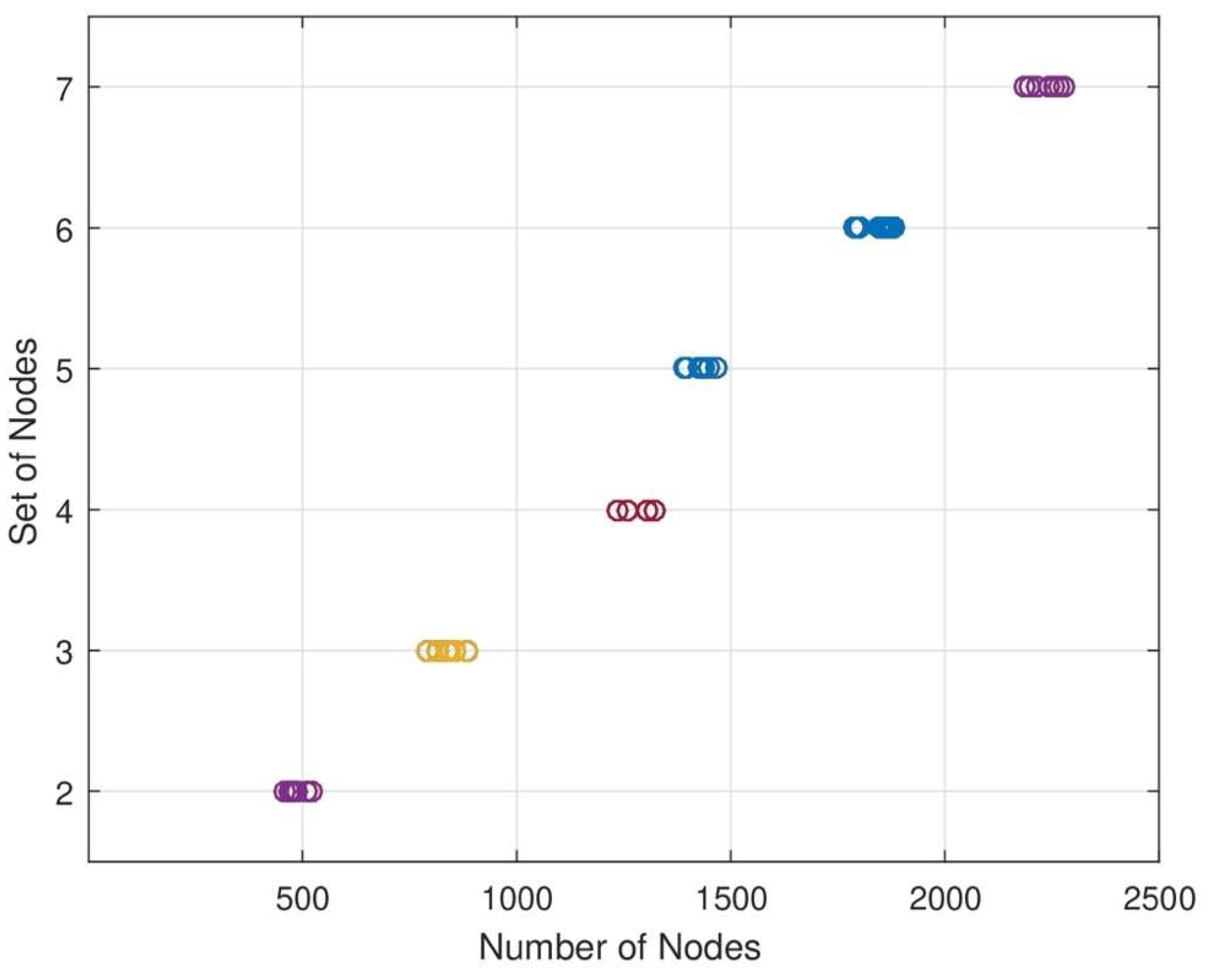
Figure 4, The network area is divided into subnetwork. Since there are different subnetworks and base stations needed for data analysis, Different nodes are located in each set of nodes in each subnetwork when designing the strategy. We can increase or decrease the length of each set of network areas. When the length of nodes in each set increases and decreases, the energy consumption level will be changed. In this figure, the energy consumption level is directly proportional to the data sensing rate of each node.
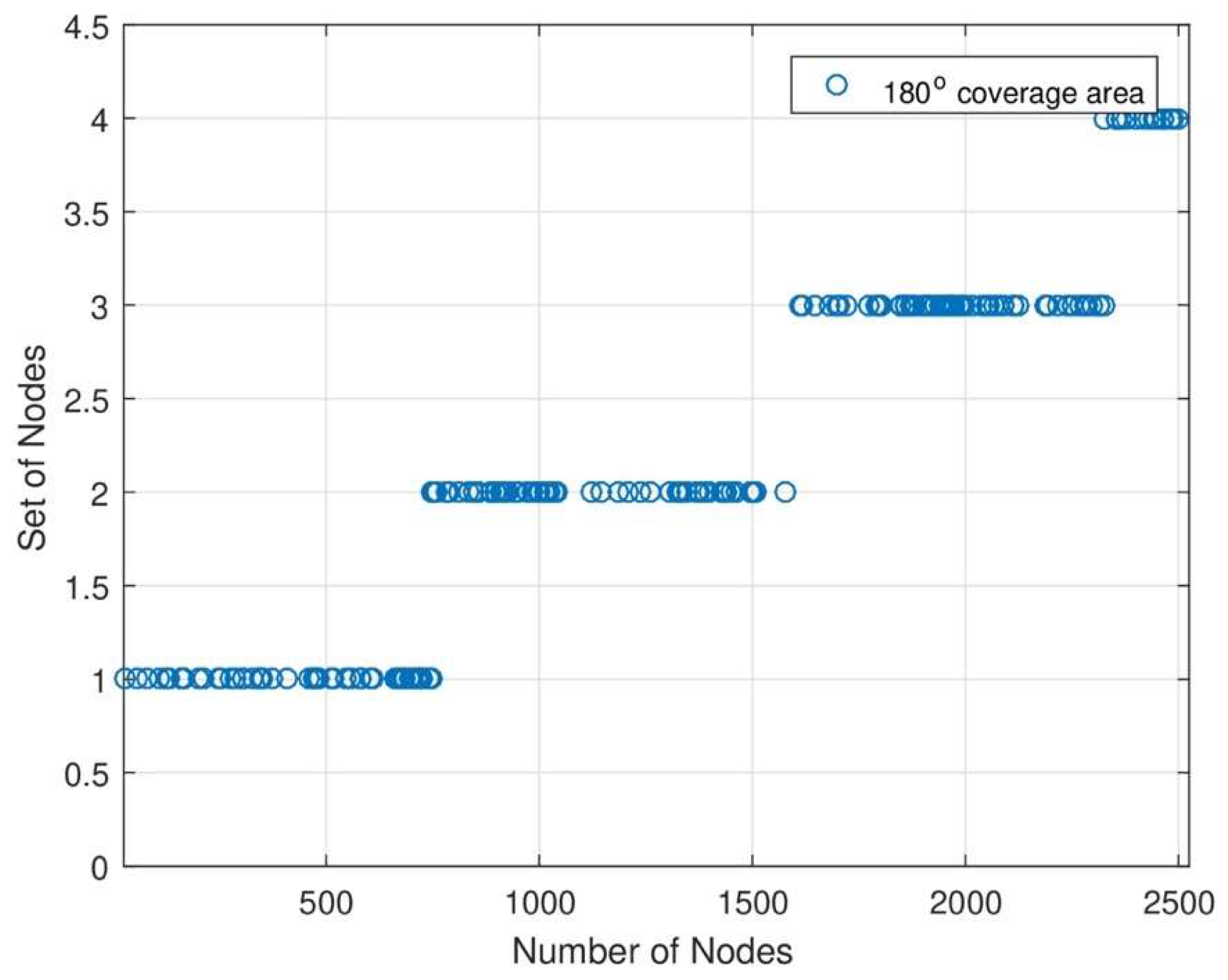
Figure 5 shows that the network coverage area is
. In this graph, the DC charger covers several nodes for energy transmission. DC changes its orientation to transmit energy to each sensor node. When the number of nodes increases, the energy rate will also increase. The remaining area of DC will be covered with MC for energy transmission. With the help of joint energy transmission, each sensor node consumes maximum energy from MC and DC. The percentage of data in each set of networks. In each set of networks, we see each node’s data transmission percentage. When the number of nodes increases, the energy transmission level should also increase. The novelty of this work is that the data transmission level is still maintained because of MC and DC joint energy transmission.
In
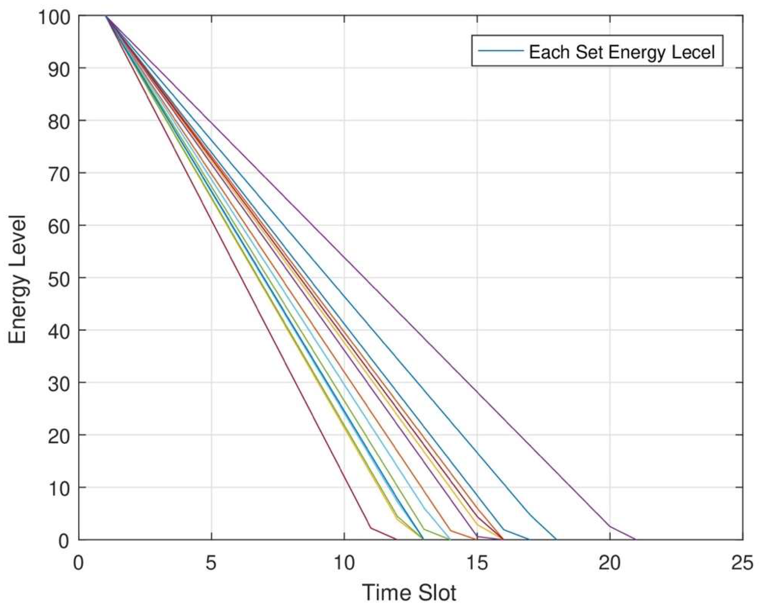
Figure 6, the energy level of each node at different time slots is shown. In RWSNs, DC and MC jointly cover each set of network areas for maximum energy transmission to each sensor node. In RWSNs, we change the time slot allocation at each set of nodes for maximum energy transmission. As a result, each node consumes maximum energy from each node at each time slot. We can improve the network efficiency after transmitting maximum energy to each node.
Figure 7 shows the set charging range. It is shown initially that the energy level will rise and then decline with an increase. At the segment point and the final point, the whole charging system possesses the highest system efficiency. In the subnetwork, each node is deployed in different sets. First, in the network area, each node’s residual energy is more, indicating that the network works perpetually. However, simultaneously, in each set of networks, the residual energy of each node will reach maximum. This situation indicates the maximum energy would be transmitted in each node. But at the same time, the node that consumes low energy would inevitably obtain more energy with the help of DC and MC. In the maximum energy transmission phenomenon, all nodes in each set can harvest maximum energy from MC and DC.
Figure 8 shows the energy consumption of each node is the same as the data transmission level change at each time slot. In this graph, the data transmission level of each node is the same as the number of node changes in each set of networks. MC shows the energy transmission level of each node. When MC changes its charging cycle orientation, the energy level of each node is still maintained. At each round, nodes have different energy levels. When the energy level of each node is low, sensor nodes charge requests to the MC. MC comes in the set of networks to transmit energy to each set of nodes.
In
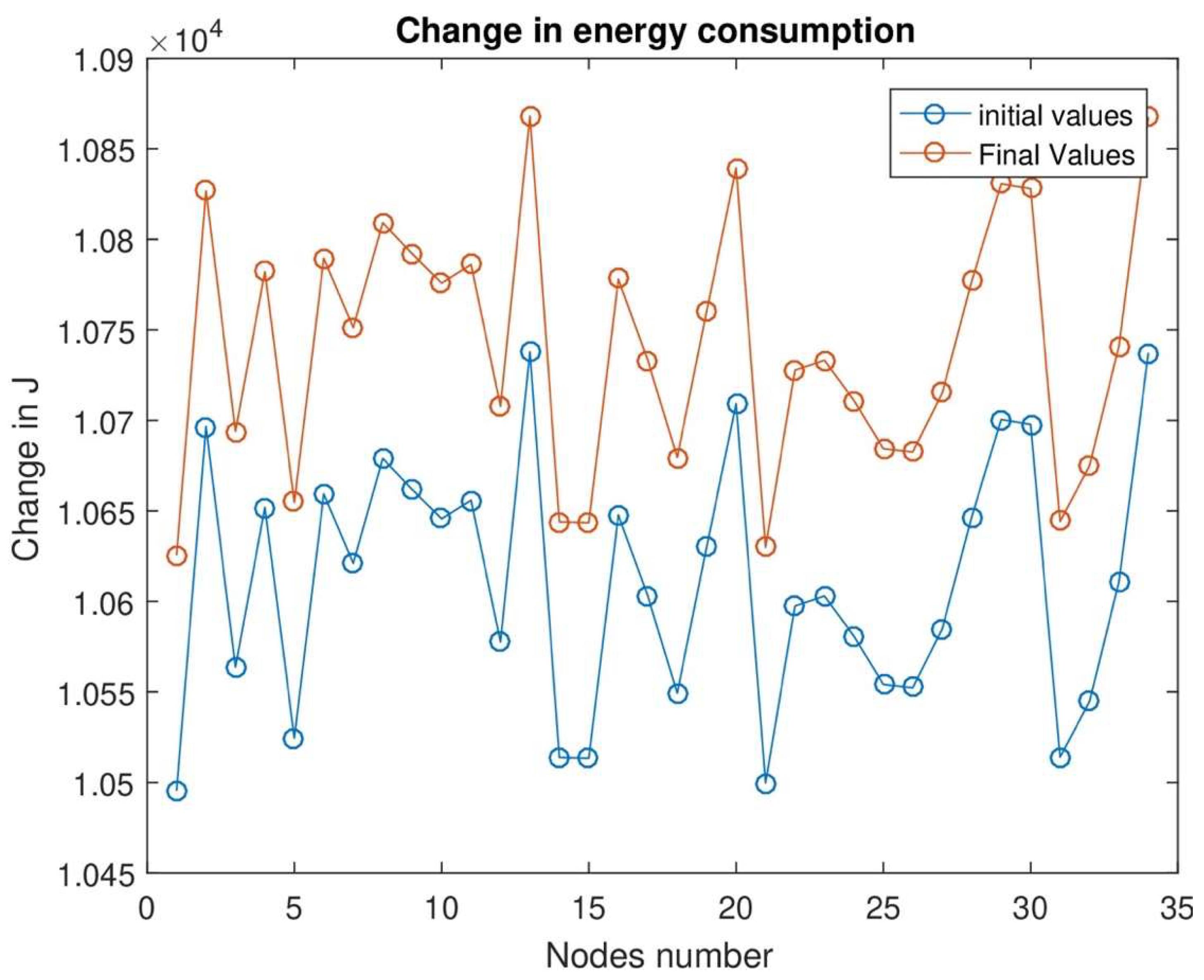
Figure 9, we divide energy consumption into two stages: one is the initial level, and the other is the final level. At the initial level, the energy consumption level is low, and the data sensing level is low. In the final stage, we see that the energy consumption level will increase as data consumption and data transmission levels will increase.
In
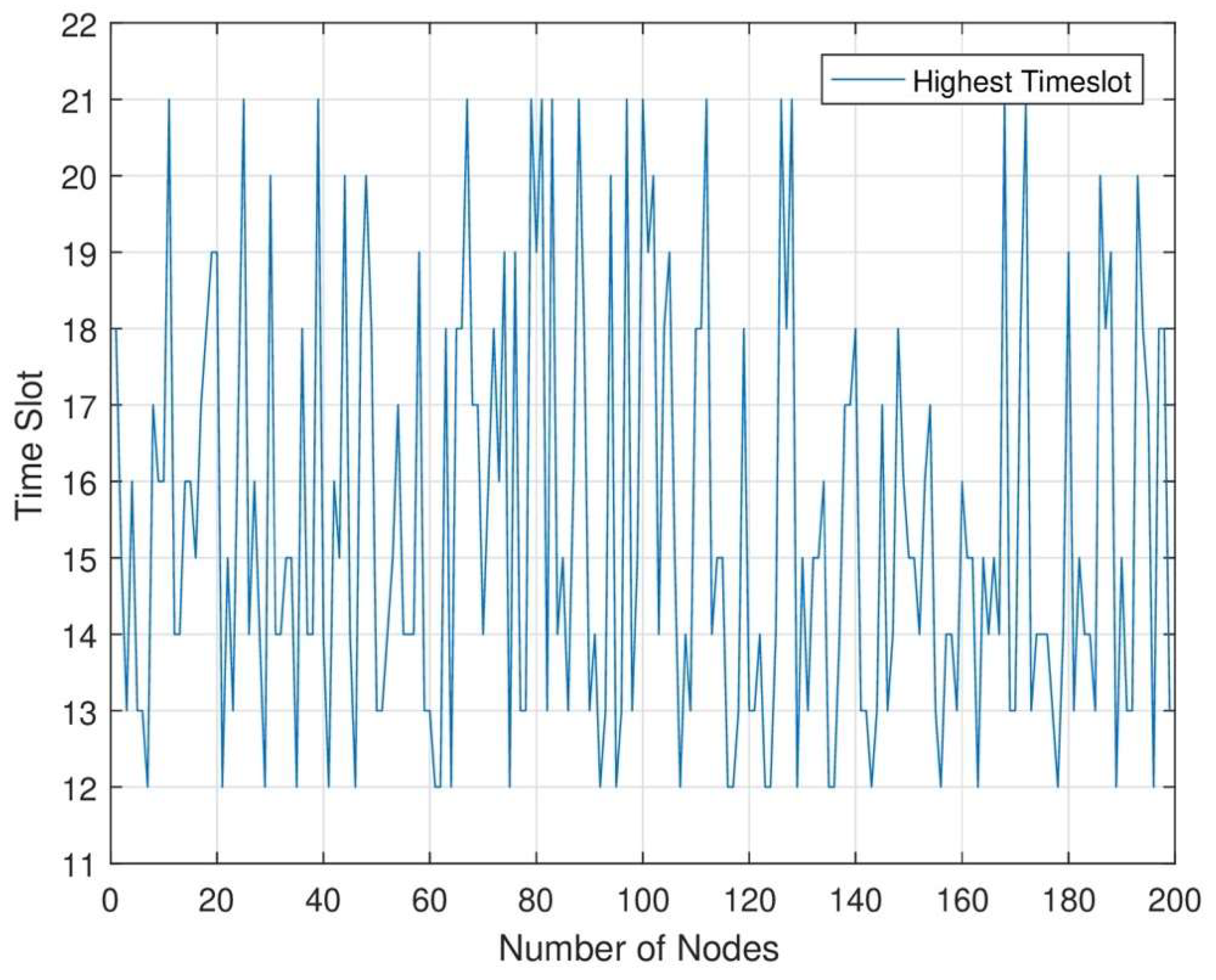
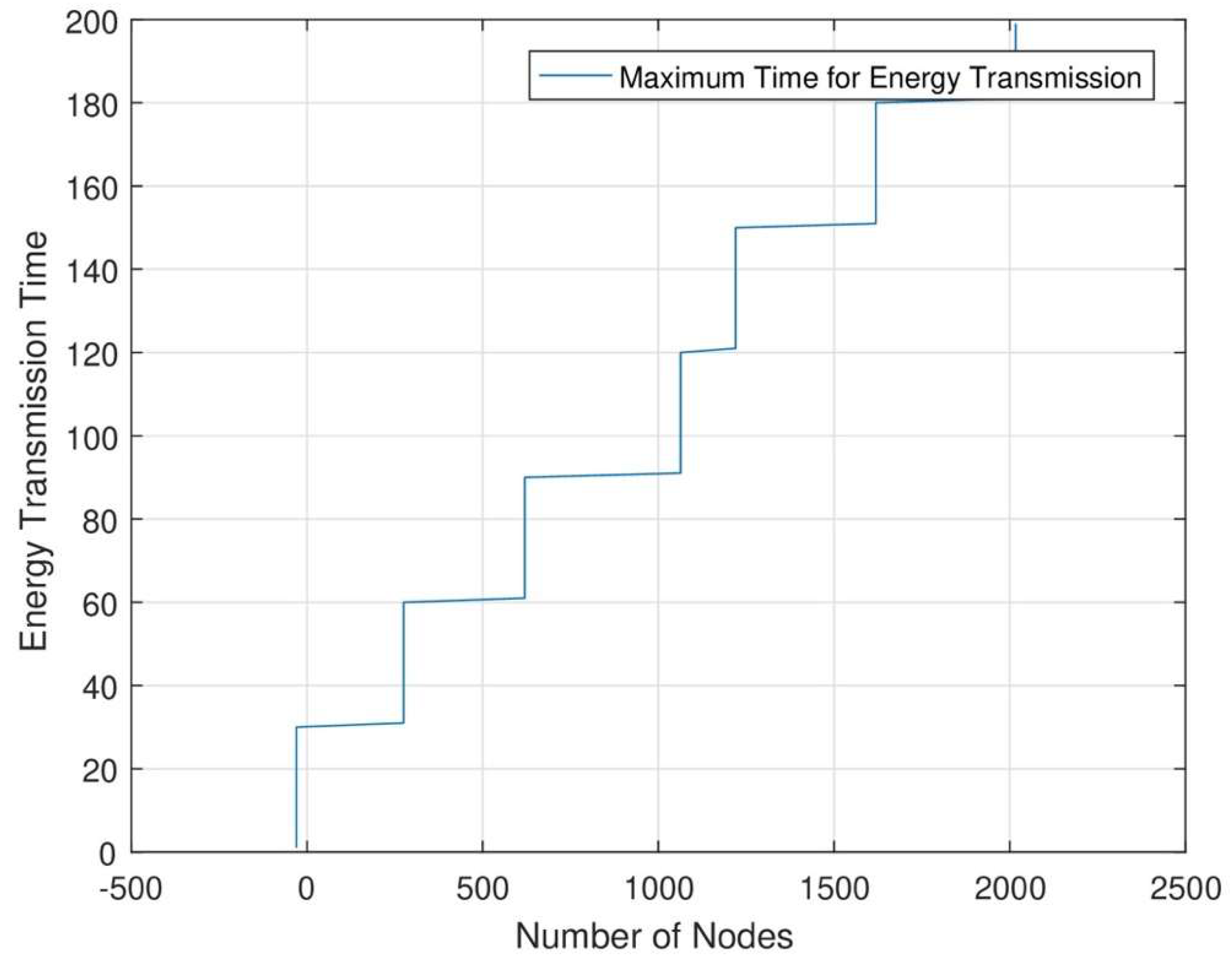
Figure 10, in each time slot, when the number of nodes increases data sensing rate and data transmission rate will increase. In the network area, when energy transmission is maximum in each node, we can increase each node’s time slot. When the time slot increases data sensing and data transmission rate is maximum. In RWSNs, we see maximum time slot allocation. As a result, we can see that in each set of networks, we allocate a maximum time slot to sense maximum data from each sensor node.
In RWSNs, the node stops working as its residual energy will be below its threshold level. Therefore, the lifetime will be to end. We can see the residual energy of each node is still high, especially the nodes with lower consumption. Without an energy supply, the network cannot work the network only runs for the minimum time. The only MC charging scheduling does not maintain the functionality of RWSNs perpetually. All nodes do not gain energy before a specific level of energy. We need to replenish energy to maximum each node before its threshold level. In this regard we need to use MC and DC jointly to properly transmit energy to each node to ensure the network functions perpetually. It is clearly shown that our proposed joint energy transmission algorithm supports more nodes for maximum energy transmission.
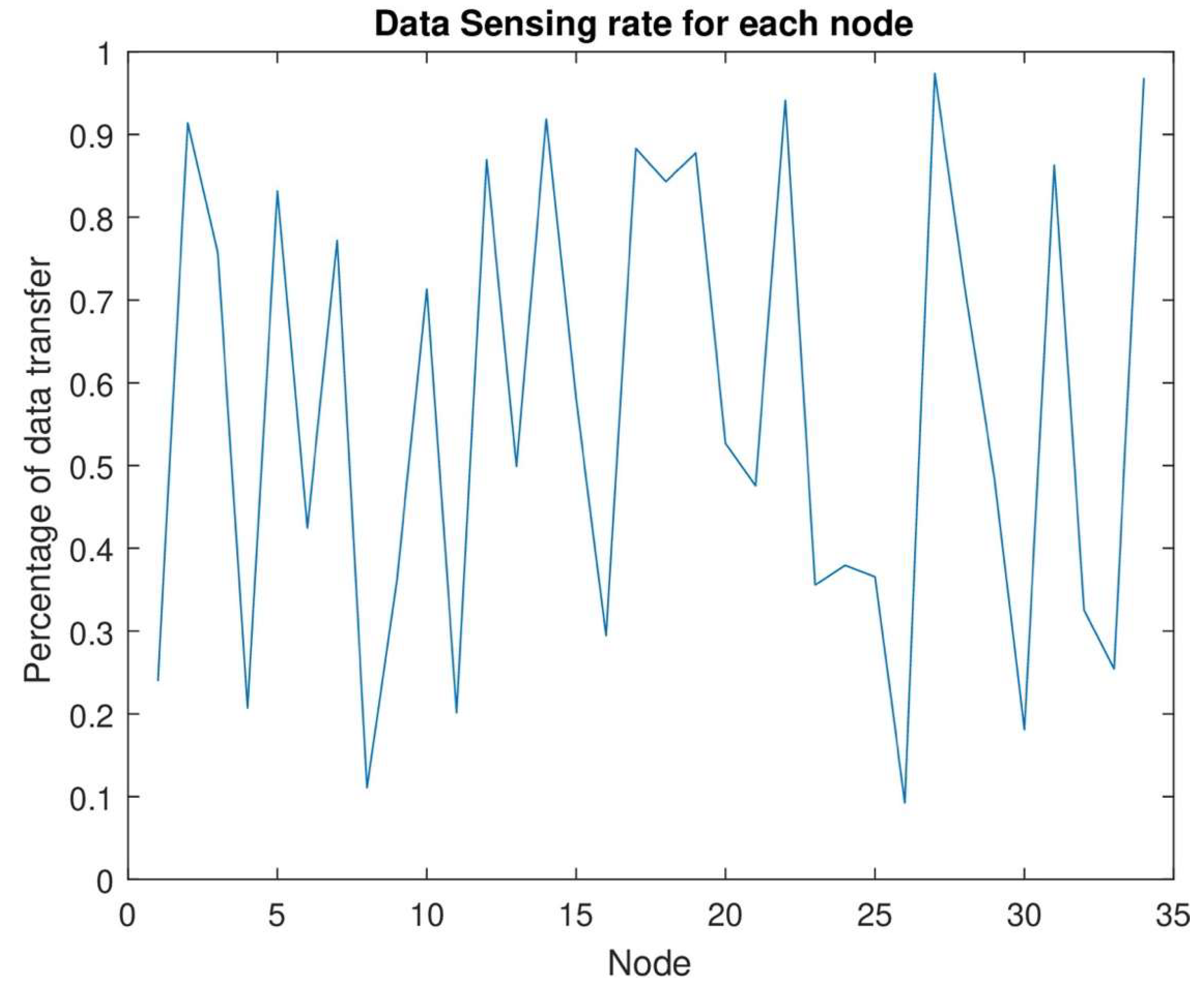
Figure 11 shows the data sensing rate from the lowest rate to the highest sensing rate. The data sensing rate starts from the lowest level. As the number of nodes increases, the energy consumption rate will also increase. After the consumption of maximum energy, each node can sense maximum data. In this figure, the data sensing rate starts from zero when the energy level is near the dead level. At each time slot when the energy consumption level increases, the data sensing and data transmission rate should be high. By joint energy transmission of each node, when the number of nodes will increase, the data sensing rate should be increased. The network area has no data loss because of the highest energy transmission from MC and DC.
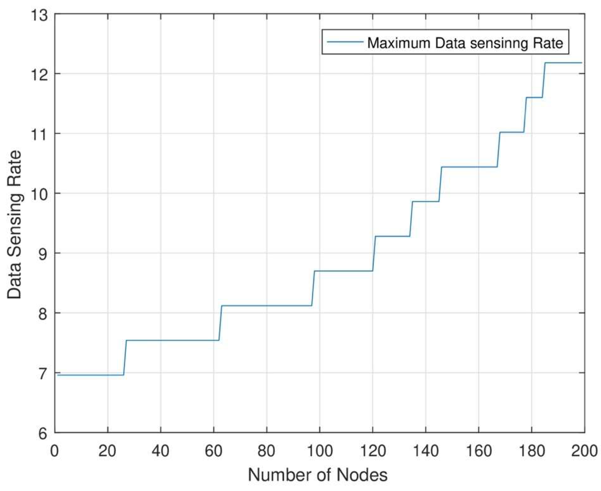
Figure 12 shows the maximum sensing rate of each node in each set. In this network, each node senses maximum data and transmits maximum data after transmitting maximum energy to each node. Each node can sense maximum data after transmission of maximum energy. As a result, the figure shows each node’s highest data sensing rate. In this research, we can increase network efficiency with the help of maximum energy transmission from MC and DC and maximum data transmission.
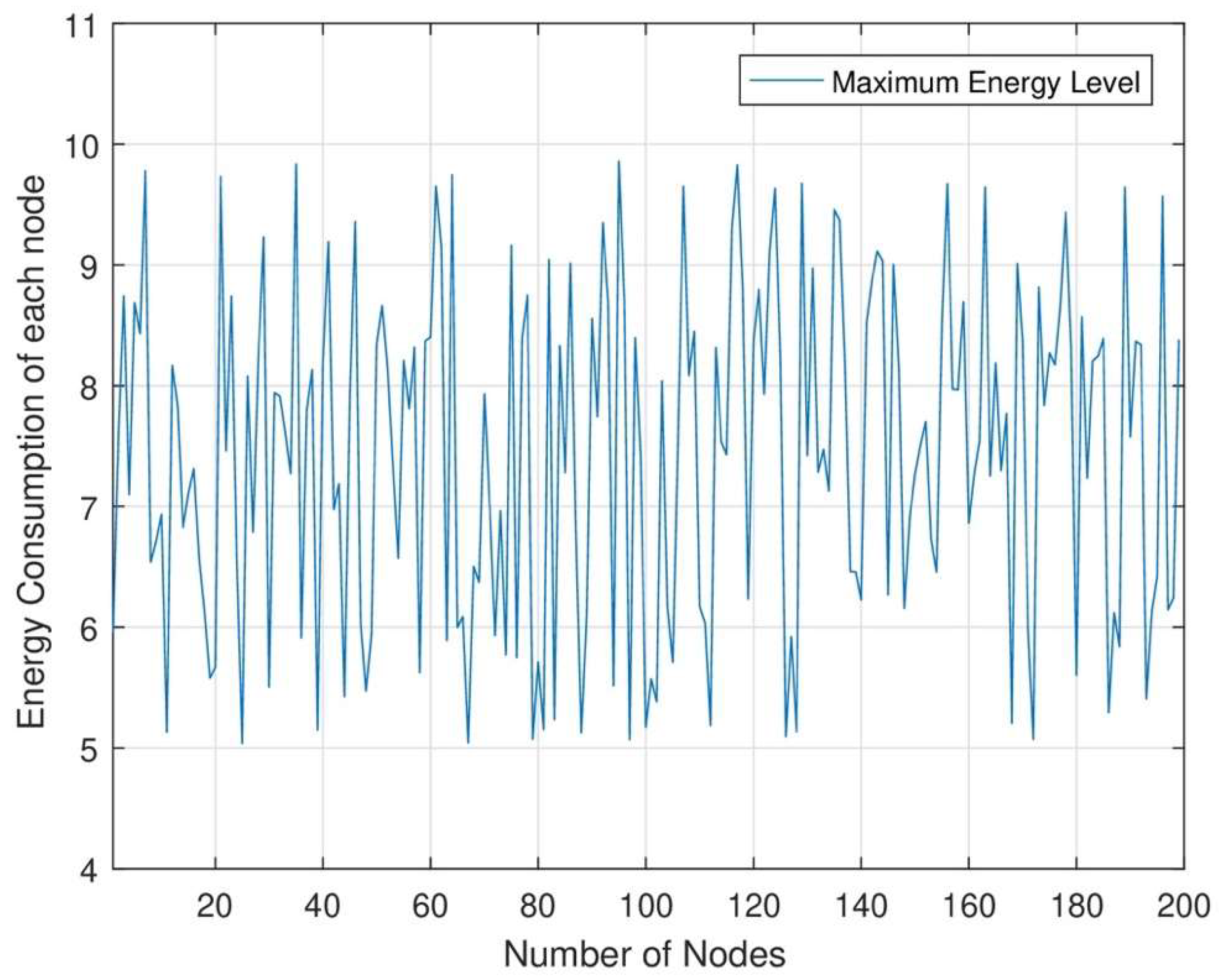
Figure 13 shows the highest energy consumption rate to the low energy rate. As the timeslot and number of nodes increase at each set of nodes, the energy level will decrease. When the number of nodes increases in the network area, the energy level will decrease. The efficiency of our proposed research is that each node maintains its working power to sense data from each node. Our proposed research shows that each node senses maximum data at each timeslot with the maximum energy transmission.
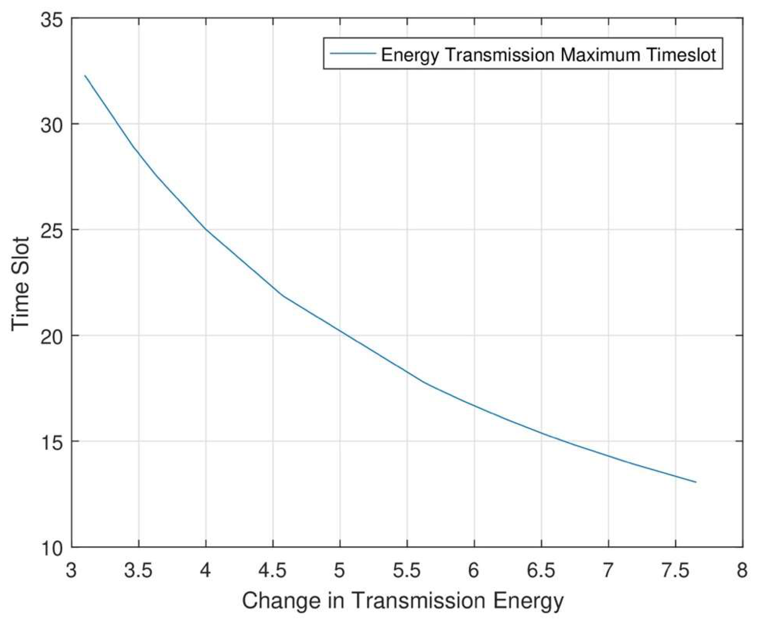
Figure 14 shows the minimum slot length of each node. In RWSNs, the slot length is higher when data transmission and data sensing rates are high. When MC travels to find different sets from different distances for energy transmission, our proposed work’s performance will be increased. As a result, sensor nodes must be charged more frequently when MC and DC work together for energy transmission. MC and DC transmit energy to each node when both chargers send charging requests to each node.
9. Conclusion
In this research, we have studied the optimization charging path problem for rechargeable wireless sensor networks. To obtain a reasonable mobile charging route for the sensor node. We formulated the problem to sense maximum data from the area of the network. Our mobile charging schedule routing path can ensure the efficient work of RWSNs under certain constraint conditions. Meanwhile, it can maximize the network lifetime, which helps sense the maximum data from the area of RWSNs. We use the TSP algorithm, which helps transmit maximum energy to each sensor node fully. The existing algorithm works very effectively to transmit energy to each node. After the transmission of maximum energy to each node then, all nodes can easily sense data from the area of the network.
References
- M. Nobre, I. Silva, and L. A. Guedes, “Routing and scheduling algorithms for WirelessHART networks: A survey,” Sensors, vol. 15, no. 5, pp. 9703-9740, 2015.
- H. Nakayama, N. Ansari, A. Jamalipour, and N. Kato, “Fault-resilient sensing in wireless sensor networks,” Computer Communications, vol. 30, no. 11-12, pp. 2375-2384, 2007.
- T. Tony, S. Soh, M. Lazarescu, and K.-W. Chin, “Link scheduling in rechargeable wireless sensor networks with a dual-battery system,” in ICC 2021-IEEE International Conference on Communications, 2021: IEEE, pp. 1-7.
- H. Sharma, A. Haque, and F. Blaabjerg, “Machine learning in wireless sensor networks for smart cities: a survey,” Electronics, vol. 10, no. 9, p. 1012, 2021.
- D. Prasannababu and T. Amgoth, “Joint mobile wireless energy transmitter and data collector for rechargeable wireless sensor networks,” Wireless Networks, vol. 28, no. 8, pp. 3563-3576, 2022.
- P. Zhong, Y. Zhang, S. Ma, X. Kui, and J. Gao, “RCSS: A real-time on-demand charging scheduling scheme for wireless rechargeable sensor networks,” Sensors, vol. 18, no. 5, p. 1601, 2018.
- B. Tong, Z. Li, G. Wang, and W. Zhang, “How wireless power charging technology affects sensor network deployment and routing,” in 2010 IEEE 30th International Conference on Distributed Computing Systems, 2010: IEEE, pp. 438-447.
- Y. Shi, L. Xie, Y. T. Hou, and H. D. Sherali, “On renewable sensor networks with wireless energy transfer,” in 2011 Proceedings IEEE INFOCOM, 2011: IEEE, pp. 1350-1358.
- S. He, J. Chen, F. Jiang, D. K. Yau, G. Xing, and Y. Sun, “Energy provisioning in wireless rechargeable sensor networks,” IEEE transactions on mobile computing, vol. 12, no. 10, pp. 1931-1942, 2012.
- C. Wright, “The Gattilusio Lordships and the Aegean World 1355-1462,” in The Gattilusio Lordships and the Aegean World 1355-1462: Brill, 2014.
- Y. Peng, Z. Li, W. Zhang, and D. Qiao, “Prolonging sensor network lifetime through wireless charging,” in 2010 31st IEEE Real-Time Systems Symposium, 2010: IEEE, pp. 129-139.
- A. Kurs, A. Karalis, R. Moffatt, J. D. Joannopoulos, P. Fisher, and M. Soljacic, “Wireless power transfer via strongly coupled magnetic resonances,” science, vol. 317, no. 5834, pp. 83-86, 2007.
- Z. Li, Y. Peng, W. Zhang, and D. Qiao, “J-RoC: A joint routing and charging scheme to prolong sensor network lifetime,” in 2011 19th IEEE International Conference on Network Protocols, 2011: IEEE, pp. 373-382.
- S. Zhang, J. Wu, and S. Lu, “Collaborative mobile charging for sensor networks,” in 2012 IEEE 9th international conference on mobile ad-hoc and sensor systems (MASS 2012), 2012: IEEE, pp. 84-92.
- K. Li, H. Luan, and C.-C. Shen, “Qi-ferry: Energy-constrained wireless charging in wireless sensor networks,” in 2012 IEEE Wireless Communications and Networking Conference (WCNC), 2012: IEEE, pp. 2515-2520.
- H. Dai, X. Wu, G. Chen, L. Xu, and S. Lin, “Minimizing the number of mobile chargers for large-scale wireless rechargeable sensor networks,” Computer Communications, vol. 46, pp. 54-65, 2014.
- C. Hu and Y. Wang, “Minimizing the number of mobile chargers to keep large-scale WRSNs working perpetually,” International Journal of Distributed Sensor Networks, vol. 11, no. 6, p. 782952, 2015.
- C. Wang, J. Li, F. Ye, and Y. Yang, “Multi-vehicle coordination for wireless energy replenishment in sensor networks,” in 2013 IEEE 27th International Symposium on Parallel and Distributed Processing, 2013: IEEE, pp. 1101-1111.
- W. Liang, W. Xu, X. Ren, X. Jia, and X. Lin, “Maintaining large-scale rechargeable sensor networks perpetually via multiple mobile charging vehicles,” ACM Transactions on Sensor Networks (TOSN), vol. 12, no. 2, pp. 1-26, 2016.
- J. Wang, T. Si, X. Wu, X. Hu, and Y. Yang, “Sustaining a perpetual wireless sensor network by multiple on-demand mobile wireless chargers,” in 2015 IEEE 12th International Conference on Networking, Sensing and Control, 2015: IEEE, pp. 533-538.
- H. Dai, Y. Zhang, X. Wang, A. X. Liu, and G. Chen, “Omnidirectional chargability with directional antennas,” IEEE Transactions on Mobile Computing, 2023.
- H. Dai, X. Wang, A. X. Liu, H. Ma, and G. Chen, “Optimizing wireless charger placement for directional charging,” in IEEE INFOCOM 2017-IEEE Conference on Computer Communications, 2017: IEEE, pp. 1-9.
- J.-R. Jiang and J.-H. Liao, “Efficient wireless charger deployment for wireless rechargeable sensor networks,” Energies, vol. 9, no. 9, p. 696, 2016.
- T.-C. Chiu, Y.-Y. Shih, A.-C. Pang, J.-Y. Jeng, and P.-C. Hsiu, “Mobility-aware charger deployment for wireless rechargeable sensor networks,” in 2012 14th Asia-Pacific Network Operations and Management Symposium (APNOMS), 2012: IEEE, pp. 1-7.
- H. Dai, X. Wu, L. Xu, G. Chen, and S. Lin, “Using minimum mobile chargers to keep large-scale wireless rechargeable sensor networks running forever,” in 2013 22nd international conference on computer communication and networks (ICCCN), 2013: IEEE, pp. 1-7.
- J. Zhang and X. Jia, “Capacity analysis of wireless mesh networks with omni or directional antennas,” in IEEE INFOCOM 2009, 2009: IEEE, pp. 2881-2885.
- H.-N. Dai, K.-W. Ng, R. C.-W. Wong, and M.-Y. Wu, “On the capacity of multi-channel wireless networks using directional antennas,” in IEEE INFOCOM 2008-The 27th Conference on Computer Communications, 2008: IEEE, pp. 628-636.
- Q. Wang, H.-N. Dai, Z. Zheng, M. Imran, and A. V. Vasilakos, “On connectivity of wireless sensor networks with directional antennas,” Sensors, vol. 17, no. 1, p. 134, 2017.
- H.-N. Dai and Q. Zhao, “On the delay reduction of wireless ad hoc networks with directional antennas,” EURASIP Journal on Wireless Communications and Networking, vol. 2015, pp. 1-13, 2015.
- X. Li, J. Xu, H.-N. Dai, Q. Zhao, C. F. Cheang, and Q. Wang, “On modeling eavesdropping attacks in wireless networks,” Journal of Computational Science, vol. 11, pp. 196-204, 2015.
- H. Yousefi, M. Malekimajd, M. Ashouri, and A. Movaghar, “Fast aggregation scheduling in wireless sensor networks,” IEEE transactions on wireless communications, vol. 14, no. 6, pp. 3402-3414, 2015.
- T. Basikolo and H. Arai, “APRD-MUSIC algorithm DOA estimation for reactance based uniform circular array,” IEEE Transactions on Antennas and Propagation, vol. 64, no. 10, pp. 4415-4422, 2016.
|
Disclaimer/Publisher’s Note: The statements, opinions and data contained in all publications are solely those of the individual author(s) and contributor(s) and not of MDPI and/or the editor(s). MDPI and/or the editor(s) disclaim responsibility for any injury to people or property resulting from any ideas, methods, instructions or products referred to in the content. |
© 2024 by the authors. Licensee MDPI, Basel, Switzerland. This article is an open access article distributed under the terms and conditions of the Creative Commons Attribution (CC BY) license (http://creativecommons.org/licenses/by/4.0/).
