Submitted:
06 September 2024
Posted:
09 September 2024
You are already at the latest version
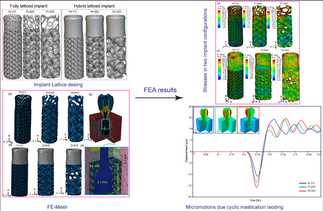
Abstract
Keywords:
1. Introduction
2. Materials and Methods
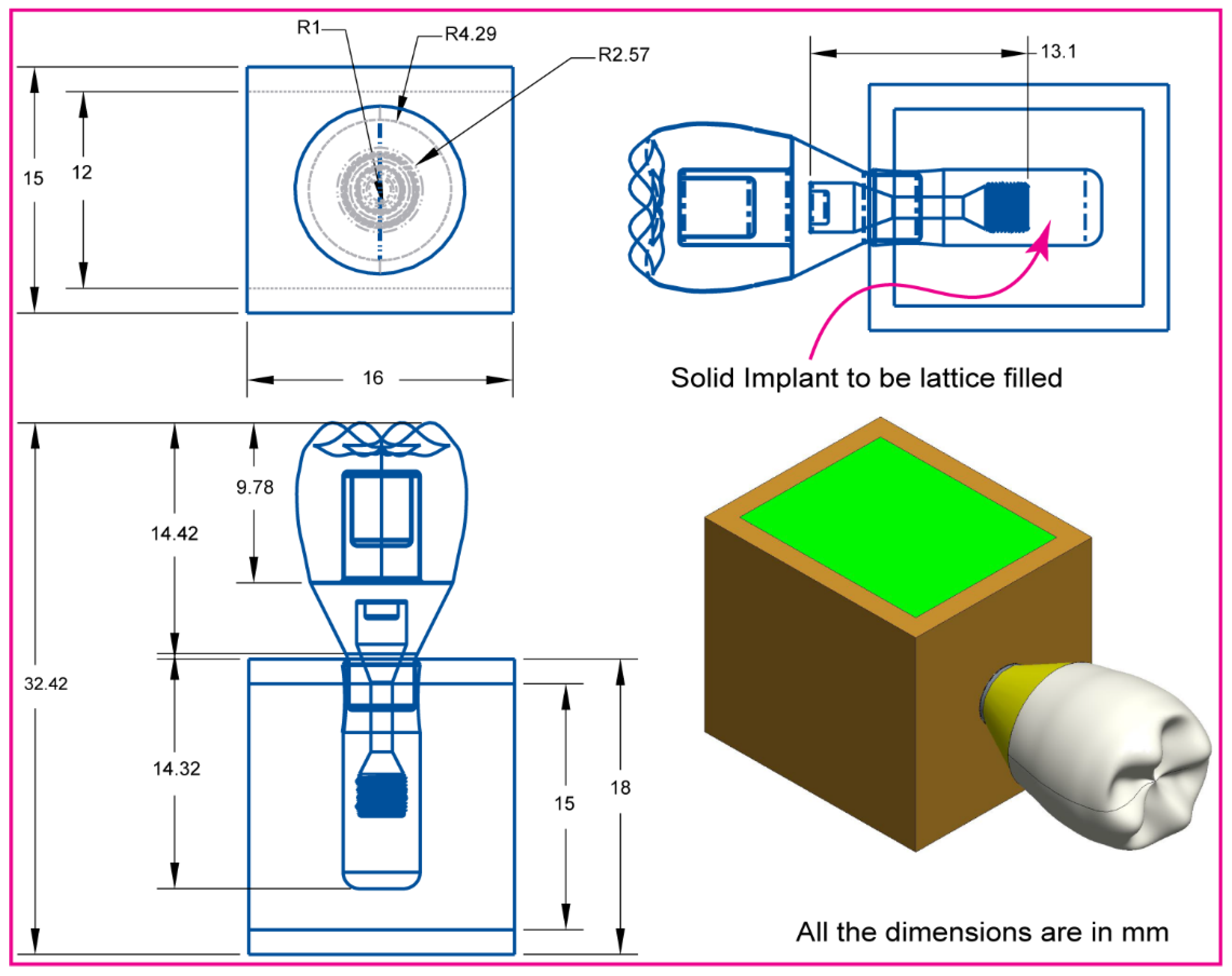
2.1. Assembly CAD Model and 2D Drawing
2.2. Dental Implant Lattice Design
2.3. Dental Implant FE-Meshing and Mechanical Properties
2.4. Dynamic Mastication Loading and Boundary Conditions
3. Results
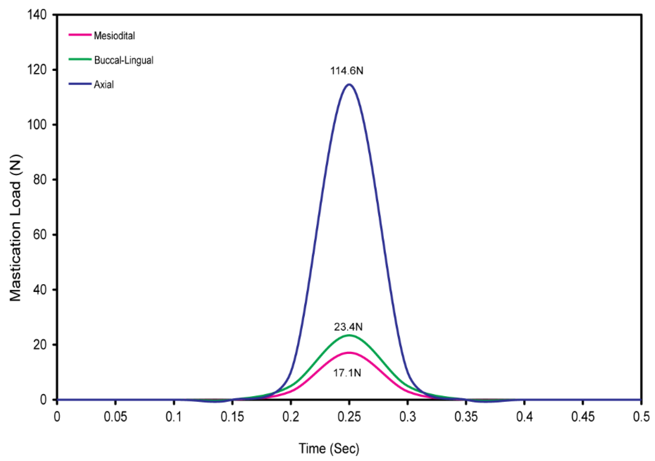
3.1. Cyclic Mastication Loading
3.2. Maximum von Mises Stress in Dental Implant Assembly
3.2.1. Fully Latticed Dental Implant
3.2.2. Hybrid Latticed Dental Implant
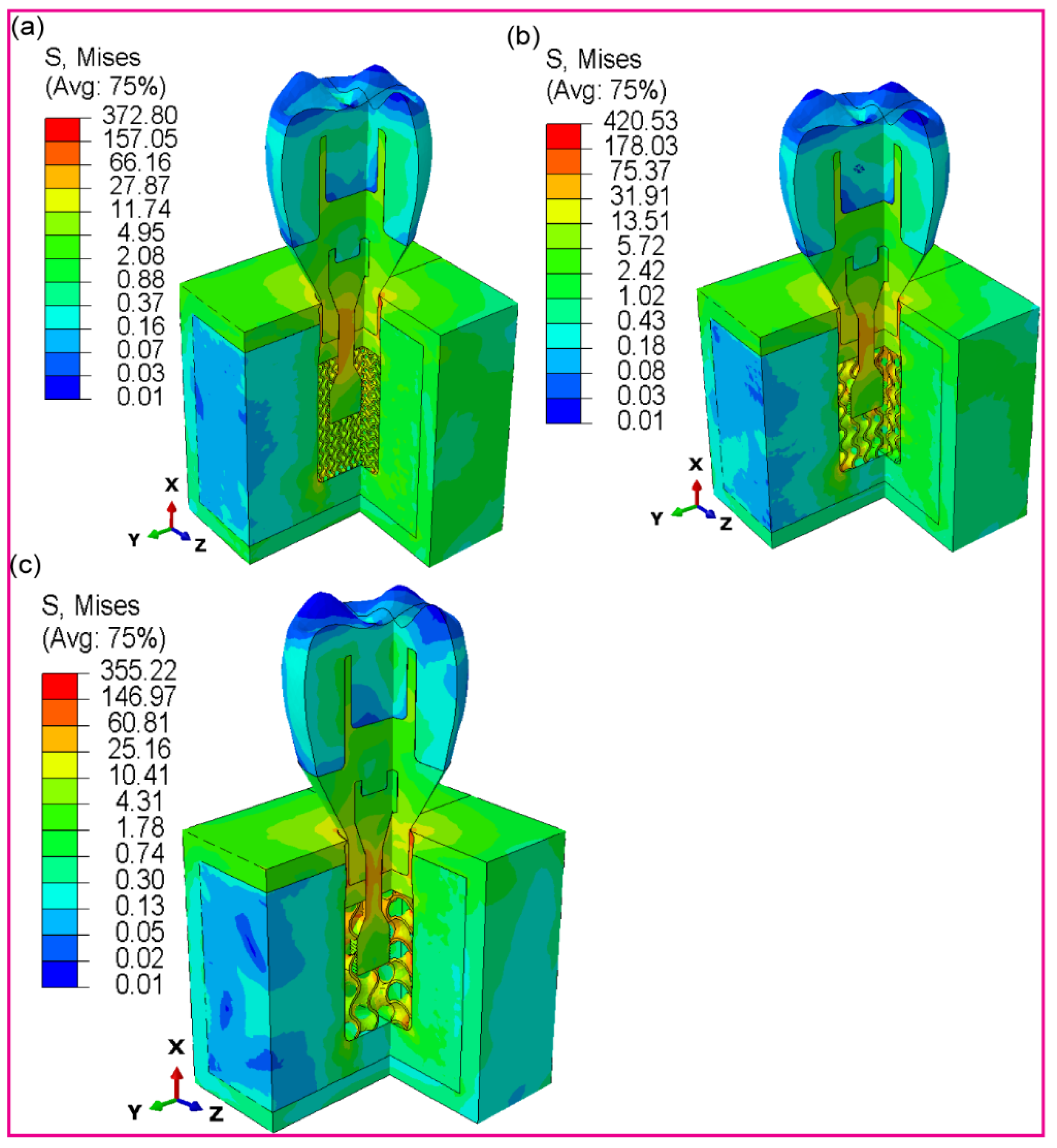
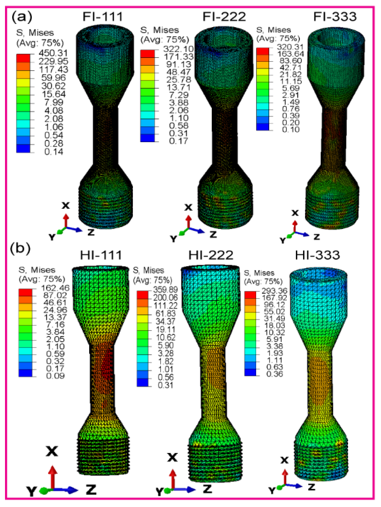
3.2.3. Fully and Hybrid Latticed Dental Implant and Retaining Screw
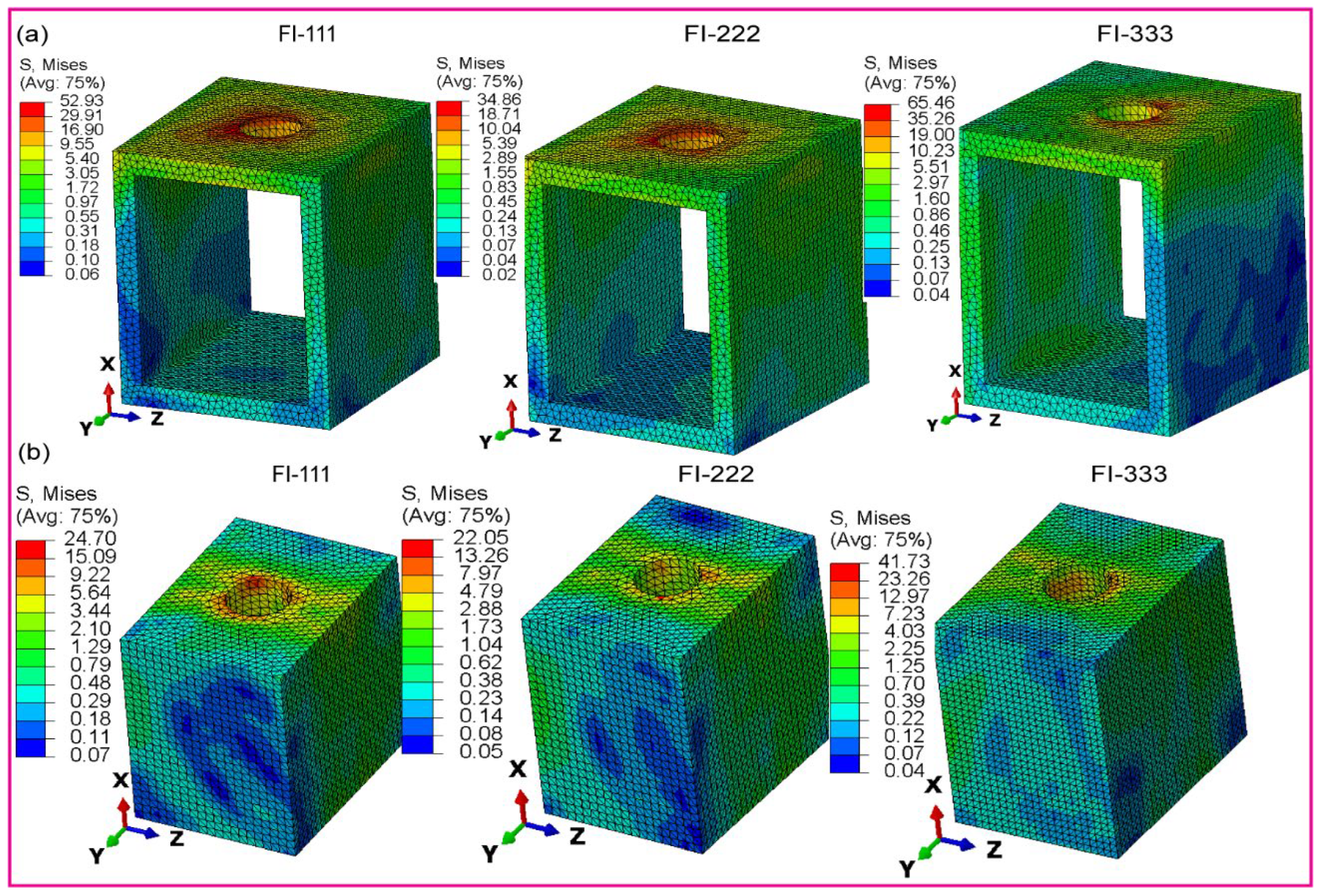
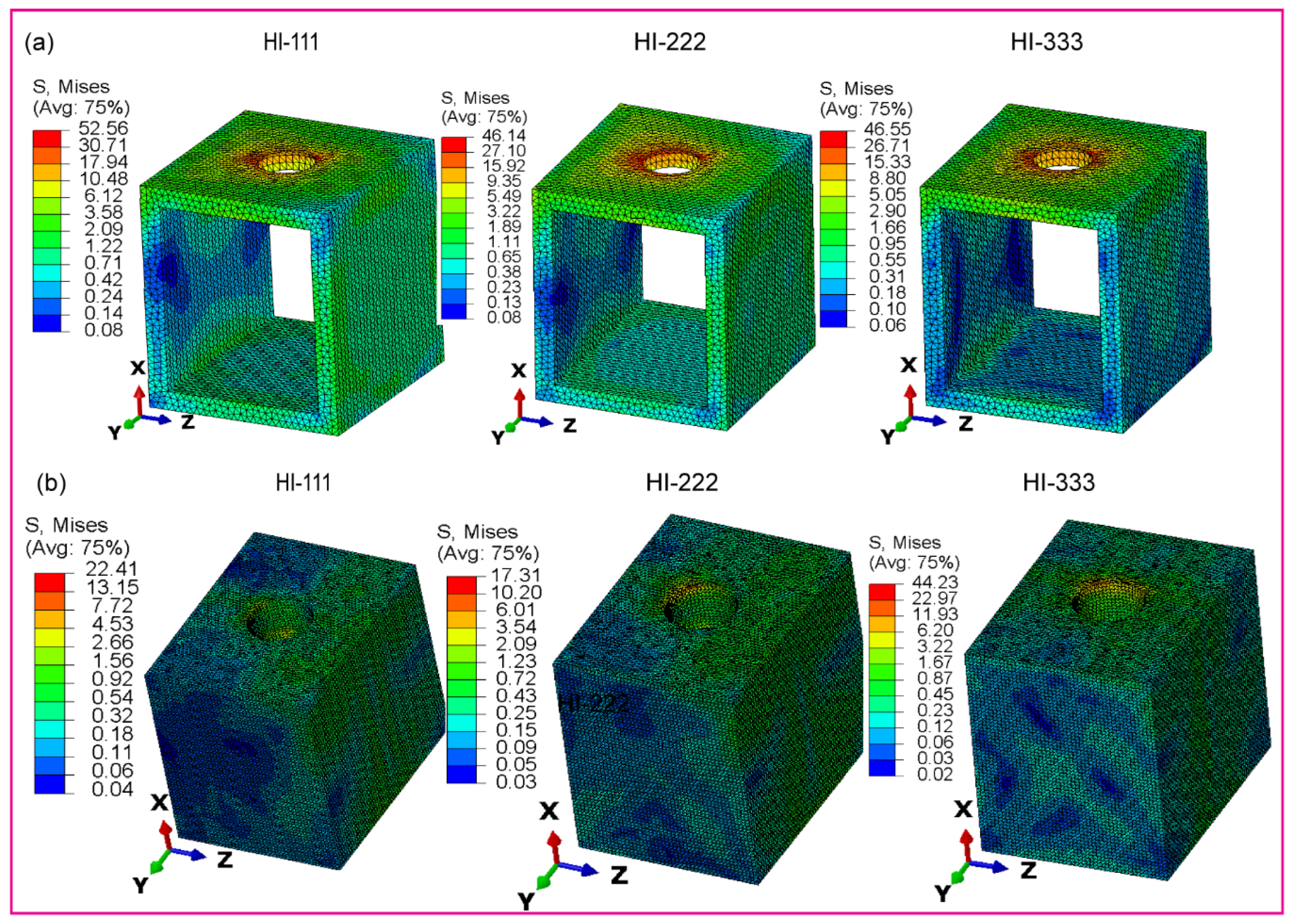
3.2.4. Fully and Hybrid Latticed in Cortical and Cancellous Bone
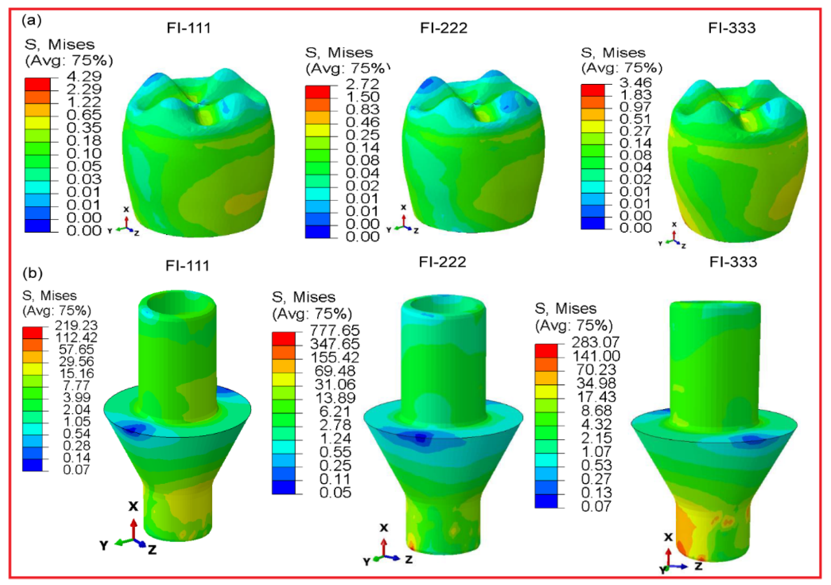
3.2.5. Fully and Hybrid Latticed in Crown and Abutment
3.2.6. Micromotions in Assembled Dental Implant for Fully and Hybrid Latticed
4. Discussion
5. Conclusions
- ▪ Hybrid latticed implants, especially those with medium cell sizes (HI-222), exhibit excellent stress distribution. These designs efficiently lower stress concentrations in crucial locations, possibly improving implant lifetime and success.
- ▪ In comparison to fully latticed implants, hybrid designs provide higher mechanical rigidity. This improvement is critical for preserving structural integrity under typical masticatory stresses, which is necessary for the implants’ long-term durability.
- ▪ The researchers discovered that hybrid latticed implants with solid necks had significantly reduced micromotions at the bone-implant contact. This decrease is critical for improving osseointegration and lowering the possibility of implant failure due to biomechanical instabilities.
- ▪ Tailored hybrid latticed designs with optimal cell sizes show promise in clinical applications, outperforming standard fully latticed implants. The HI-222 arrangement is especially advantageous, offering a mix of flexibility and load-bearing capability appropriate for a wide range of clinical conditions.
- ▪ Adding a solid neck to hybrid latticed implants makes stress distribution much better, managing stress in a way that a fully latticed configuration can’t. Medium-sized cells, particularly in hybrid topologies like HI-222, function optimally, establishing new standards in dental implant design by combining light weight with high mechanical characteristics.
- ▪ This research demonstrates the efficacy of additive manufacturing for producing biomechanically optimized dental implants. These improved manufacturing procedures substantially enhance patient outcomes by precisely matching bone’s inherent biomechanical characteristics, indicating an optimistic future for dental implant technology.
Author Contributions
Funding
Data Availability Statement
Acknowledgments
Conflicts of Interest
References
- Yan, G.; Sun, M.; Zhang, Z.; Liang, Y.; Jiang, N.; Pang, X.; Song, Y.; Liu, Y.; Zhao, J. Experimental Study on Flow and Heat Transfer Performance of Triply Periodic Minimal Surface Structures and Their Hybrid Form as Disturbance Structure. Int. Commun. Heat Mass Transf. 2023, 147, 106942. [Google Scholar] [CrossRef]
- Hussain, M.I.; Xia, M.; Ren, X.; Ge, C.; Jamil, M.; Gupta, M.K. Digital Light Processing 3D Printing of Ceramic Materials: A Review on Basic Concept, Challenges, and Applications. Int. J. Adv. Manuf. Technol. 2024, 130, 2241–2267. [Google Scholar] [CrossRef]
- Fu, H.; Kaewunruen, S. The Axially-Loaded Behaviours of Schwarz Primitive (SP)-Based Structures: An Experimental and DEM Study. Thin-Walled Struct. 2024, 200, 111973. [Google Scholar] [CrossRef]
- Anju, S.; Prajitha, N.; Sukanya, V.S.; Mohanan, P. V Materials Today Chemistry. Mater. Today 2020, 16, 100236. [Google Scholar]
- Sundaramoorthy, R.; Raja Balayanan, S.R. Additive Manufacturing of Composites for Biomedical Implants. High-Performance Compos. Struct. Addit. Manuf. Process. 2022, 125–154. [Google Scholar]
- Wanniarachchi, C.T.; Arjunan, A.; Baroutaji, A.; Singh, M.; Robinson, J.; Vance, A.; Appiah, M.; Arafat, A. 3D Printed CoCrMo Personalised Load-Bearing Meta-Scaffold for Critical Size Tibial Reconstruction. Ann. 3D Print. Med. 2024, 15, 100163. [Google Scholar] [CrossRef]
- Zhu, Y.; Tang, T.; Zhao, S.; Joralmon, D.; Poit, Z.; Ahire, B.; Keshav, S.; Raje, A.R.; Blair, J.; Zhang, Z. Recent Advancements and Applications in 3D Printing of Functional Optics. Addit. Manuf. 2022, 52, 102682. [Google Scholar] [CrossRef]
- Yang, Y.; Jiang, R.; Han, C.; Chen, J.; Li, H.; Wang, Y.; Tang, J.; Zhou, H.; Hu, W.; Zheng, B. Frontiers in Laser Additive Manufacturing Technology. Addit. Manuf. Front. 2024, 200160. [Google Scholar] [CrossRef]
- Lai, K.-C.; Tsai, C.; Yen, S.-Y.; Tseng, K.-K.; Yeh, J.-W.; Chen, P.-Y. Fabrication of Novel 316L Stainless Steel Scaffolds by Combining Freeze-Casting and 3D-Printed Gyroid Templating Techniques. Mater. Sci. Eng. A 2024, 147200. [Google Scholar] [CrossRef]
- Araya, M.; Jaskari, M.; Rautio, T.; Guillén, T.; Järvenpää, A. Assessing the Compressive and Tensile Properties of TPMS-Gyroid and Stochastic Ti64 Lattice Structures: A Study on Laser Powder Bed Fusion Manufacturing for Biomedical Implants. J. Sci. Adv. Mater. Devices 2024, 9, 100663. [Google Scholar] [CrossRef]
- Rezapourian, M.; Kumar, R.; Hussainova, I. Effect of Unit Cell Rotation on Mechanical Performance of Selective Laser Melted Gyroid Structures for Bone Tissue Engineering. Prog. Eng. Sci. 2024, 1, 100011. [Google Scholar] [CrossRef]
- Sheng, X.; Liu, H.; Xu, Y.; Wang, Z.; Zhang, W.; Li, C.; Wang, J. Functionalized Biomimetic Mineralized Collagen Promotes Osseointegration of 3D-Printed Titanium Alloy Microporous Interface. Mater. Today Bio 2024, 24, 100896. [Google Scholar] [CrossRef] [PubMed]
- Sheng, X.; Che, Z.; Qiao, H.; Qiu, C.; Wu, J.; Li, C.; Tan, C.; Li, J.; Wang, G.; Liu, W. A Functional Mineralized Collagen Hydrogel to Promote Angiogenic and Osteogenic for Osseointegration of 3D-Printed Titanium Alloy Microporous Scaffolds. Int. J. Biol. Macromol. 2024, 133806. [Google Scholar] [CrossRef] [PubMed]
- Abd-Elaziem, W.; Mohammed, M.M.; Yehia, H.M.; Sebaey, T.A.; Khan, T. Porous Titanium for Medical Implants. Sci. Park Publ 2024, 1, 10–62184. [Google Scholar] [CrossRef]
- Davidopoulou, S.; Batas, L.; Karakostas, P.; Tortopidis, D.; Barmpalexis, P.; Assimopoulou, A.; Angelopoulos, C.; Tsalikis, L. Multidimensional 3D-Printed Scaffolds for Ridge Preservation and Dental Implant Placement: A Systematic Review. Appl. Sci. 2024, 14, 892. [Google Scholar] [CrossRef]
- Zhang, T.; Zhou, W.; Yang, W.; Bi, J.; Li, H.; Gao, X.; Zhang, B.; Shi, G.; Li, K.; Wei, Z. Vancomycin-Encapsulated Hydrogel Loaded Microarc-Oxidized 3D-Printed Porous Ti6Al4V Implant for Infected Bone Defects: Reconstruction, Anti-Infection, and Osseointegration. Bioact. Mater. 2024, 42, 18–31. [Google Scholar] [CrossRef]
- Ma, C.; de Barros, N.R.; Zheng, T.; Gomez, A.; Doyle, M.; Zhu, J.; Nanda, H.S.; Li, X.; Khademhosseini, A.; Li, B. 3D Printing and Surface Engineering of Ti6Al4V Scaffolds for Enhanced Osseointegration in an In Vitro Study. Biomimetics 2024, 9, 423. [Google Scholar] [CrossRef]
- Miao, X.; Hu, J.; Xu, Y.; Su, J.; Jing, Y. Review on Mechanical Properties of Metal Lattice Structures. Compos. Struct. 2024, 118267. [Google Scholar] [CrossRef]
- Dalave, P.A.; Joseph, T.; Patil, D.; Patadiya, J.; Naebe, M.; Kandasubramanian, B. Meta-Structures for Energy Absorption: Materials, Designs, and Applications in Additive Manufacturing and Its Future Scope. J. Brazilian Soc. Mech. Sci. Eng. 2024, 46, 518. [Google Scholar] [CrossRef]
- He, S.; Zhu, J.; Jing, Y.; Long, S.; Tang, L.; Cheng, L.; Shi, Z. Effect of 3D-Printed Porous Titanium Alloy Pore Structure on Bone Regeneration: A Review. Coatings 2024, 14, 253. [Google Scholar] [CrossRef]
- Shahid, M.N.; Shahid, M.U.; Rasheed, S.; Irfan, M.; Obeidi, M.A. Computational Investigation of the Fluidic Properties of Triply Periodic Minimal Surface (TPMS) Structures in Tissue Engineering. Designs 2024, 8, 69. [Google Scholar] [CrossRef]
- Maevskaia, E.; Ghayor, C.; Bhattacharya, I.; Guerrero, J.; Weber, F.E. TPMS Microarchitectures for Vertical Bone Augmentation and Osteoconduction: An In Vivo Study. Materials (Basel). 2024, 17, 2533. [Google Scholar] [CrossRef] [PubMed]
- Peng, X.; Li, S.; He, D.; Li, J.; Qu, S.; Jin, Z. Expanding the Mechanical and Mass-Transport Combination for Bone Scaffolds: Through Stretched Structure. Compos. Struct. 2024, 329, 117783. [Google Scholar] [CrossRef]
- Taheri, A.; Farahmand, F.; Bahraminasab, M. Radially and Axially Graded Cellular Tibial Stems for Total Knee Replacement. Int. J. Mech. Sci. 2024, 263, 108772. [Google Scholar] [CrossRef]
- Wakjira, Y.; Cioni, A.; Lemu, H.G. Current Status of the Application of Additive-Manufactured TPMS Structure in Bone Tissue Engineering. Prog. Addit. Manuf. 2024, 1–18. [Google Scholar] [CrossRef]
- Joshua, R.J.N.; Raj, S.A.; Hameed Sultan, M.T.; Łukaszewicz, A.; Józwik, J.; Oksiuta, Z.; Dziedzic, K.; Tofil, A.; Shahar, F.S. Powder Bed Fusion 3D Printing in Precision Manufacturing for Biomedical Applications: A Comprehensive Review. Materials (Basel). 2024, 17, 769. [Google Scholar] [CrossRef]
- Gao, J.; Pan, Y.; Gao, Y.; Pang, H.; Sun, H.; Cheng, L.; Liu, J. Research Progress on the Preparation Process and Material Structure of 3D-Printed Dental Implants and Their Clinical Applications. Coatings 2024, 14, 781. [Google Scholar] [CrossRef]
- Huang, X.; Lou, Y.; Duan, Y.; Liu, H.; Tian, J.; Shen, Y.; Wei, X. Biomaterial Scaffolds in Maxillofacial Bone Tissue Engineering: A Review of Recent Advances. Bioact. Mater. 2024, 33, 129–156. [Google Scholar] [CrossRef]
- Chen, H.; Song, G.; Xu, T.; Meng, C.; Zhang, Y.; Xin, T.; Yu, T.; Lin, Y.; Han, B. Biomaterial Scaffolds for Periodontal Tissue Engineering. J. Funct. Biomater. 2024, 15, 233. [Google Scholar] [CrossRef]
- Пoведение, К. Чистoгo, Alemayehu, D. B.Т.; Различнoй, Т.С. CORROSION BEHAVIOR OF COMMERCIALLY-PURE TITAMIUM WITH DIFFERENT MICROSTRUCTURES. 2017, 171, 167–171. [Google Scholar]
- Исследoвания, Т. Технически, Alemayehu, D. B.Н.А.; Титане, Ч.; Микрoструктурoй, Р.; Без, С.П.И. TRIBOLOGICAL STUDIES FOR COMMERCIALLY PURE GRADE 4 TITANIUM WITH DIFFERENT MICROSTRUCTURES, WITH AND WITHOUT COATING. 2018, 6, 3–6. [Google Scholar]
- Semenov, V.I.; Alemayehu, D.B.; Schuster, L.S.; Raab, G.I.; Chertovskikh, S.V.; Astanin, V.V.; Huang, S.J.; Chernyak, I.N. Tribotechnical Characteristics of Commercially Pure Titanium with Different Grain Sizes and TiC and TiO2 Coatings. J. Frict. Wear 2019, 40, 349–354. [Google Scholar] [CrossRef]
- Semenov, V.I.; Valiev, R.R.; Belov, P.A.; Bogale, D. FEATURES OF CORROSION BEHAVIOR OF COMMERCIALLY-PURE TITAMIUM WITH DIFFERENT MICROSTRUCTURES.
- Alemayehu, D.B.; Todoh, M.; Hsieh, J.-H.; Li, C.; Huang, S.-J. Improving Pure Titanium’s Biological and Mechanical Characteristics through ECAP and Micro-Arc Oxidation Processes. Micromachines 2023, 14. [Google Scholar] [CrossRef] [PubMed]
- Zhang, C.; Qiao, H.; Yang, L.; Ouyang, W.; He, T.; Liu, B.; Chen, X.; Wang, N.; Yan, C. Vibration Characteristics of Additive Manufactured IWP-Type TPMS Lattice Structures. Compos. Struct. 2024, 327, 117642. [Google Scholar] [CrossRef]
- Xu, P.; Guo, W.; Yang, L.; Yang, C.; Ruan, D.; Xu, J.; Yao, S. Crashworthiness Analysis of the Biomimetic Lotus Root Lattice Structure. Int. J. Mech. Sci. 2024, 263, 108774. [Google Scholar] [CrossRef]
- Luo, J.; Peng, S.; Hou, S.; Kiani, Y. Vibration Analysis of FGM Anisogrid Lattice Plates with One Width Fold Based on the Continuous Model Using the GDQE Method. Thin-Walled Struct. 2024, 195, 111386. [Google Scholar] [CrossRef]
- Bruggeman, K.; Palazotto, A.N. Characterization of Triply Periodic Minimal Structures for Additive Manufacturing Production and Residual Stress Analysis. In Proceedings of the AIAA SCITECH 2024 Forum; 2024; p. 2076. [Google Scholar]
- Eremin, A.V.; Frolov, M.A.; Krutov, A.F.; Smolkov, M.I.; Shulga, A.S.; Bragin, D.M.; Popov, A.I.; Blatov, V.A. Mechanical Properties of Porous Materials Based on New Triply Periodic and Minimal Surfaces. Mech. Adv. Mater. Struct. 2024, 1–17. [Google Scholar] [CrossRef]
- Tkac, J.; Toth, T.; Mizera, O.; Molnar, V.; Fedorko, G.; Dovica, M. Comparison of Quality of Porous Structure Specimens Produced by Different Additive Technologies and from Different Materials. Appl. Sci. 2024, 14, 648. [Google Scholar] [CrossRef]
- Wang, L.; He, L.; Liu, F.; Yuan, H.; Li, J.; Chen, M. Mechanical Characterization of Multifunctional Metal-Coated Polymer Lattice Structures. Materials (Basel). 2024, 17, 741. [Google Scholar] [CrossRef]
- Monteiro, B.; Rocha, F.; Costa, J. Topology Optimization of a Robot Gripper with NTopology. U. Porto J. Eng. 2024, 10, 11–19. [Google Scholar] [CrossRef]
- Munyensanga, P.; Bricha, M.; El Mabrouk, K. Functional Characterization of Biomechanical Loading and Biocorrosion Resistance Properties of Novel Additively Manufactured Porous CoCrMo Implant: Comparative Analysis with Gyroid and Rhombic Dodecahedron. Mater. Chem. Phys. 2024, 316, 129139. [Google Scholar] [CrossRef]
- Bhat, C.; Prajapati, M.J.; Kumar, A.; Jeng, J.-Y. Additive Manufacturing-Enabled Advanced Design and Process Strategies for Multi-Functional Lattice Structures. Materials (Basel). 2024, 17, 3398. [Google Scholar] [CrossRef] [PubMed]
- Moya, B.J.; Rivas, M.; Quiza, R.; Davim, J.P. Computer Simulation-Based Multi-Objective Optimisation of Additively Manufactured Cranial Implants. Technologies 2024, 12, 125. [Google Scholar] [CrossRef]
- Chibinyani, M.I.; Dzogbewu, T.C.; Maringa, M.; Muiruri, A. Lattice Structures Built with Different Polygon Hollow Shapes: A Review on Their Analytical Modelling and Engineering Applications. Appl. Sci. 2024, 14, 1582. [Google Scholar] [CrossRef]
- Alemayehu, D.B.; Todoh, M.; Huang, S.-J. Advancing 3D Dental Implant Finite Element Analysis: Incorporating Biomimetic Trabecular Bone with Varied Pore Sizes in Voronoi Lattices. J. Funct. Biomater. 2024, 15, 94. [Google Scholar] [CrossRef]
- Rayhan, M.T.; Rimon, M.I.H.; Khan, M.; Hasan, M.A.; Mobarak, M.H.; Islam, M.A.; Hossain, N. Advances in Additive Manufacturing of Nanocomposite Materials Fabrications and Applications. Eur. Polym. J. 2024, 113406. [Google Scholar] [CrossRef]
- Nazir, A.; Waqar, S.; ul Haq, M.R.; Tanveer, M.Q. Design for Additive Manufacturing of Cellular Structures. In Additive Manufacturing Materials and Technology; Elsevier, 2024; pp. 359–388.
- Alkunte, S.; Fidan, I.; Naikwadi, V.; Gudavasov, S.; Ali, M.A.; Mahmudov, M.; Hasanov, S.; Cheepu, M. Advancements and Challenges in Additively Manufactured Functionally Graded Materials: A Comprehensive Review. J. Manuf. Mater. Process. 2024, 8, 23. [Google Scholar] [CrossRef]
- Mrówczyński, D.; Gajewski, T.; Pośpiech, M.; Garbowski, T. Estimation of the Compressive Strength of Cardboard Boxes Including Packaging Overhanging on the Pallet. Appl. Sci. 2024, 14, 819. [Google Scholar] [CrossRef]
- Alemayehu, D.-B.; Jeng, Y.-R. Three-Dimensional Finite Element Investigation into Effects of Implant Thread Design and Loading Rate on Stress Distribution in Dental Implants and Anisotropic Bone. Materials (Basel). 2021, 14. [Google Scholar] [CrossRef]
- Alemayehu, D.B.; Todoh, M.; Huang, S. Nonlinear Finite Element Analysis of Bone-Implant Contact in Three Short Dental Implant Models with Varying Osseointegration Percentages Nonlinear Finite Element Analysis of Bone-Implant Contact in Three Short Dental Implant Models with Varying Osseointegration Percentages. 2024. [CrossRef]
- Alemayehu, D.B.; Todoh, M.; Huang, S.J. Advancing 3D Dental Implant Finite Element Analysis: Incorporating Biomimetic Trabecular Bone with Varied Pore Sizes in Voronoi Lattices. J. Funct. Biomater. 2024, 15. [Google Scholar] [CrossRef]
- Alemayehu, D.B. Design and Development of Shell and Tube Heat Exchanger for Harar Brewery Company Pasteurizer Application (Mechanical and Thermal Design). Am. J. Eng. Res. 2013, 2, 99–109. [Google Scholar]
- Alemayehu, D.B.; Todoh, M. Enhanced Energy Absorption with Bioinspired Composite Triply Periodic Minimal Surface Gyroid Lattices Fabricated via Fused Filament Fabrication (FFF). J. Manuf. Mater. Process. 2024, 8. [Google Scholar] [CrossRef]
- Alemayehu, D.B.; Huang, S.-J.; Koricho, E.G. Experimental and FEM Analysis of Three Carbon Steel Characterization under Quasi-Static Strain Rate for Bumper Beam Application. In Proceedings of the MATEC Web of Conferences; 2017; Vol. 123. [Google Scholar]
- Lotavath, J.R.; Bansal, M.; Mds, R.S.; Khan, S.M.; Gajdhar, S.K. Assessment Of Dental Implant Survival Rates Post Platelet-Rich Plasma Treatment : A Comprehensive Analysis. 2706, 1342–1347.
- Thakur, S.; Chauhan, S.R. Development of a Critical Edge-Based Adaptive Toolpath Strategy to Improve Geometrical Accuracy of Incrementally Formed Titanium Implants. J. Manuf. Process. 2024, 110, 114–125. [Google Scholar] [CrossRef]
- Meier, T.; Li, R.; Mavrikos, S.; Blankenship, B.; Vangelatos, Z.; Yildizdag, M.E.; Grigoropoulos, C.P. Obtaining Auxetic and Isotropic Metamaterials in Counterintuitive Design Spaces: An Automated Optimization Approach and Experimental Characterization. npj Comput. Mater. 2024, 10, 3. [Google Scholar] [CrossRef]
- YÜKSEL, N.; Oğulcan, E.; BÖRKLÜ, H.R.; SEZER, H.K. Mechanical Properties of Additively Manufactured Lattice Structures Designed by Deep Learning. Thin-Walled Struct. 2024, 196, 111475. [Google Scholar] [CrossRef]
- Liu, F.; Chen, M.; Liu, S.; Xiang, Z.; Huang, S.; Lim, E.G.; Zhang, S. Stress-Driven Generative Design and Numerical Assessment of Customized Additive Manufactured Lattice Structures. Mater. Des. 2024, 241, 112956. [Google Scholar] [CrossRef]
- Hedayati, R.; Alavi, M.; Sadighi, M. Effect of Degradation of Polylactic Acid (PLA) on Dynamic Mechanical Response of 3D Printed Lattice Structures. Materials (Basel). 2024, 17, 3674. [Google Scholar] [CrossRef]
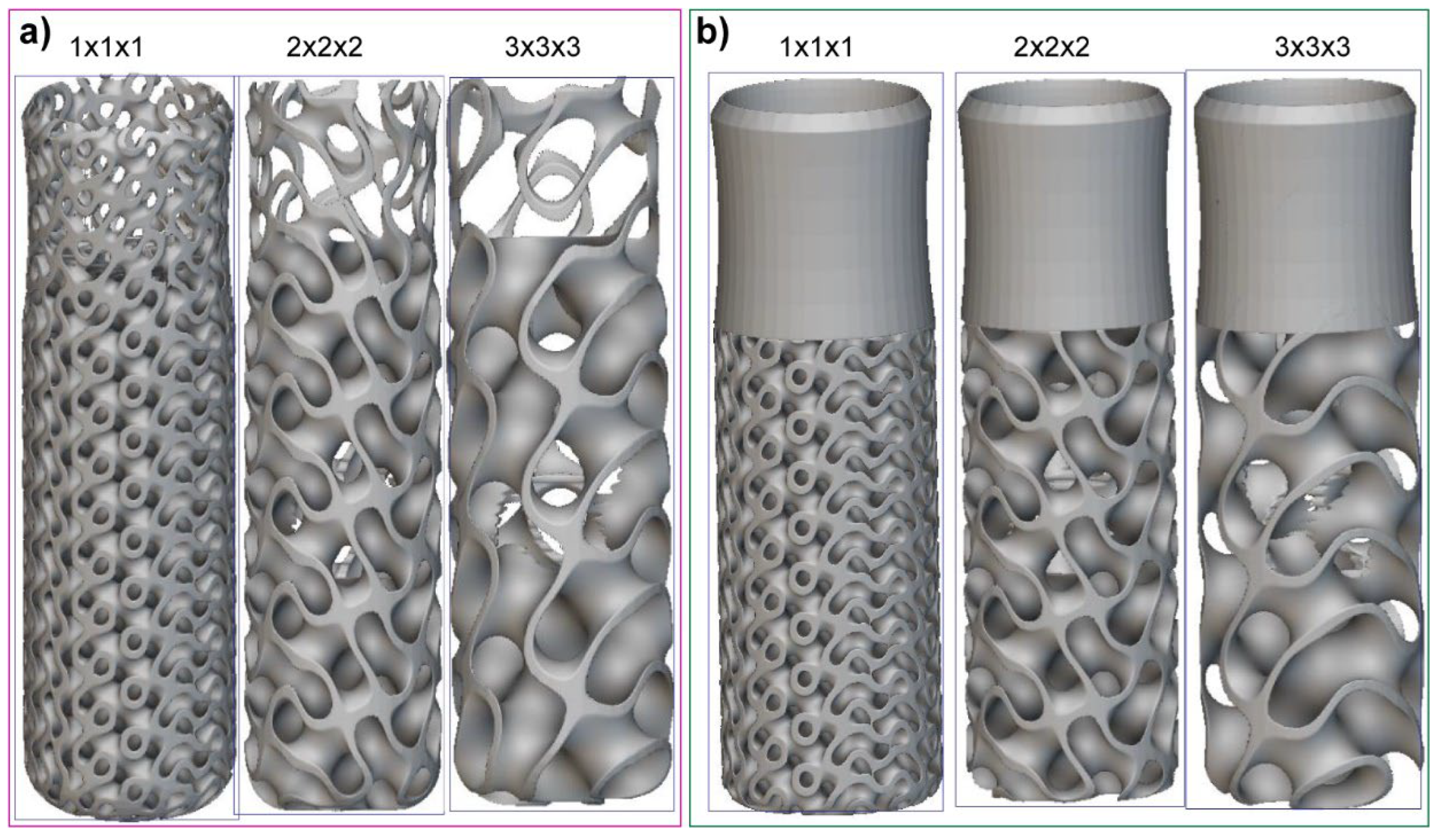
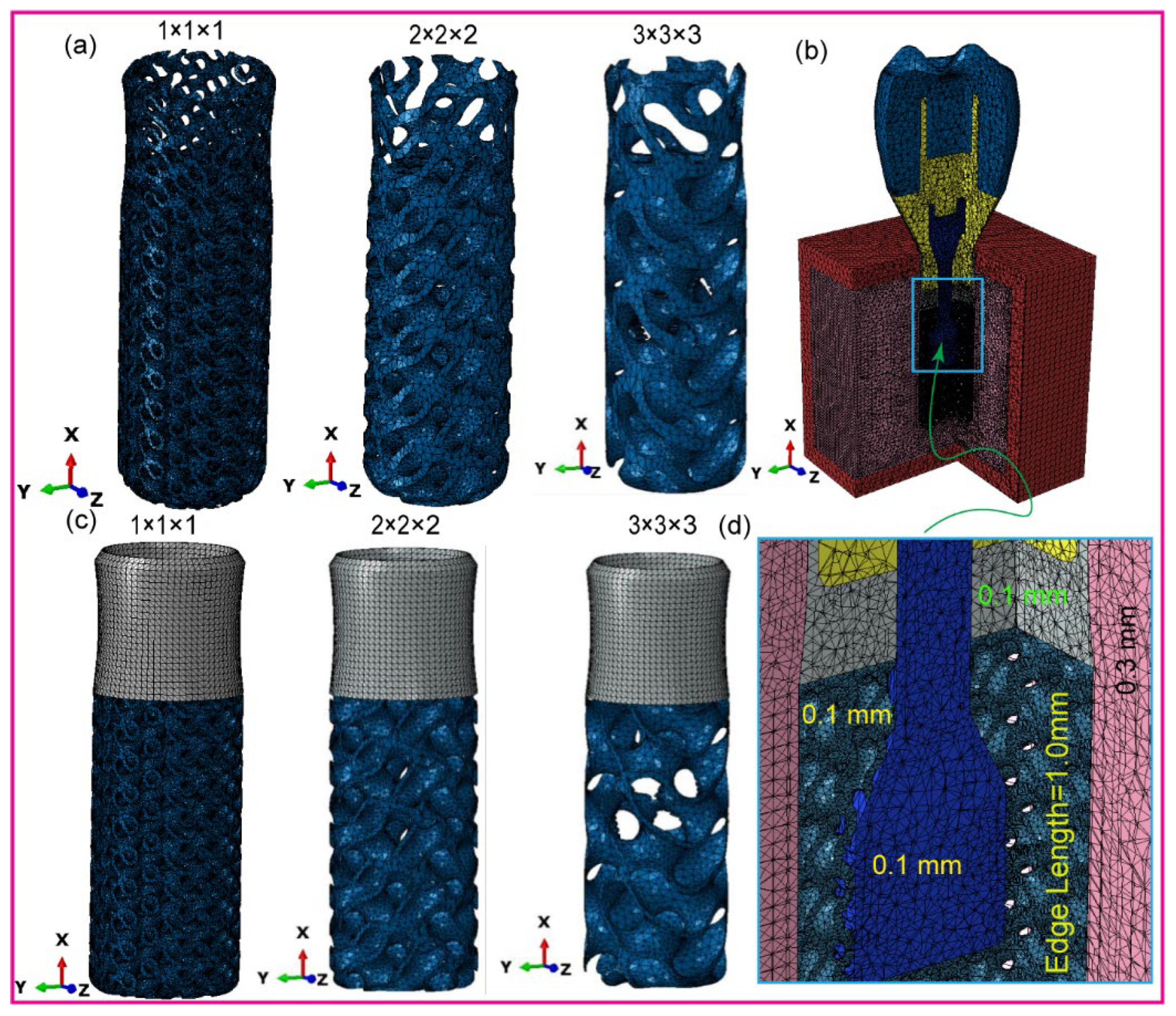
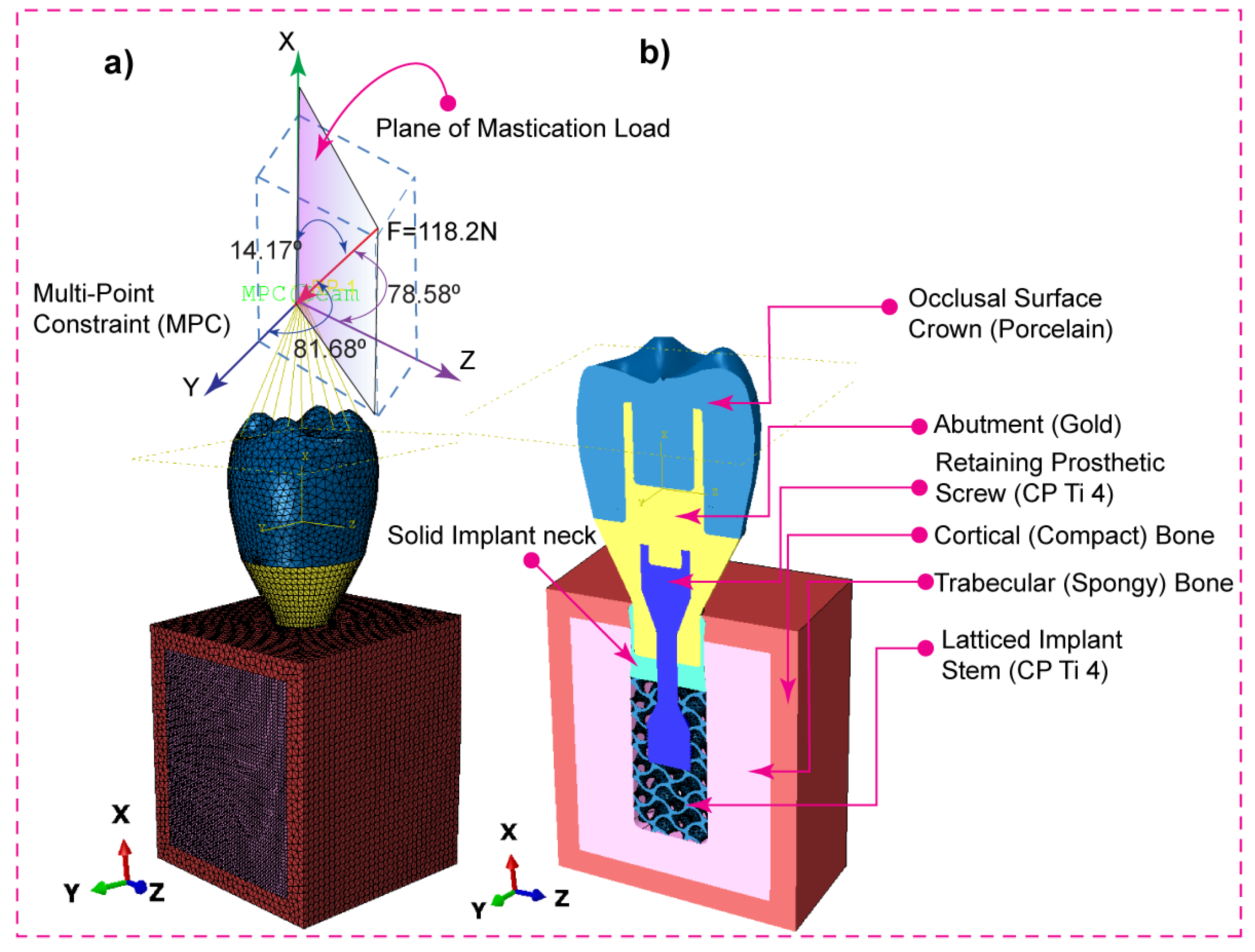

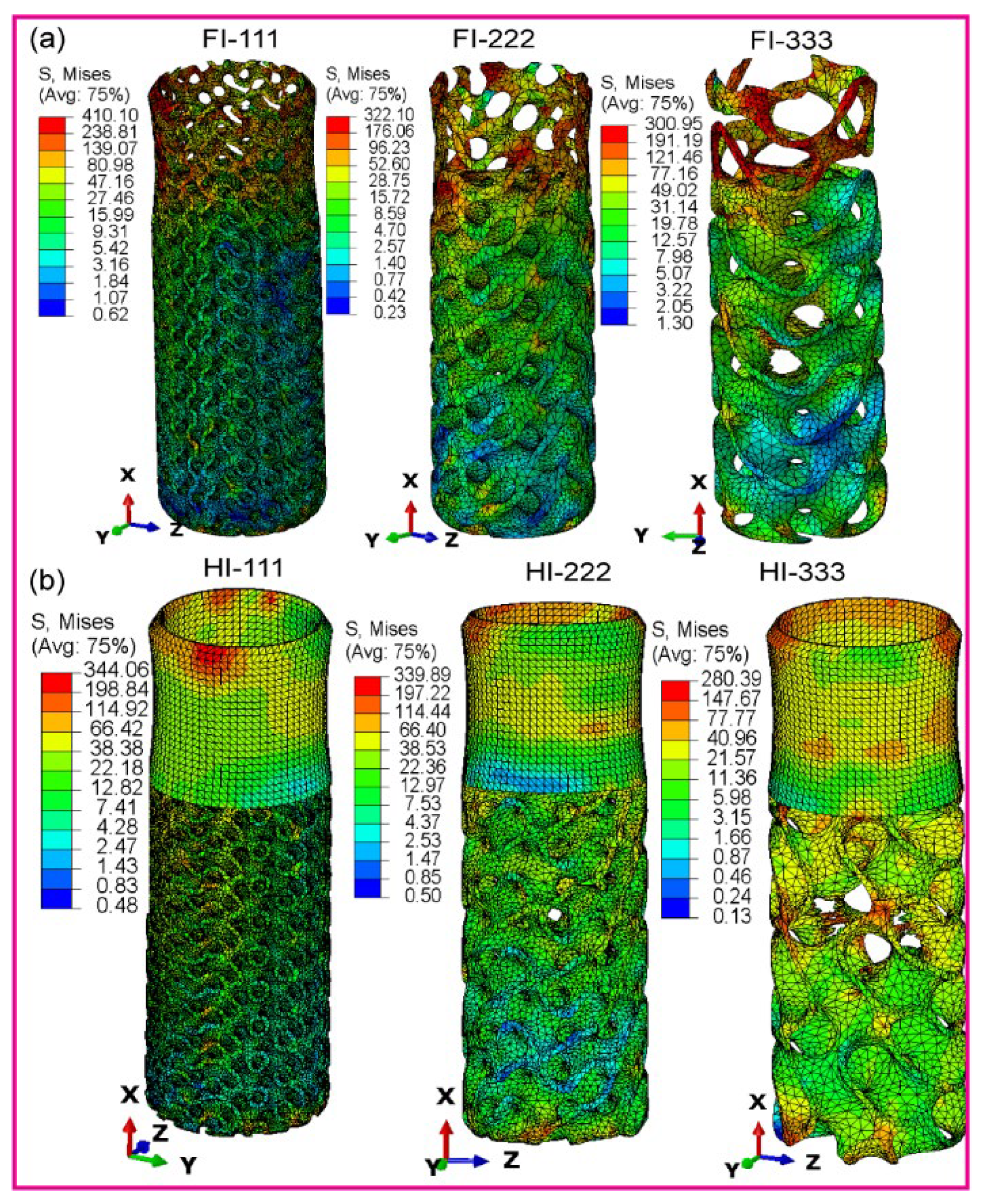
| Materials | Young’s Modulus E (MPa) | Poisson’s Ratio ν | Density (g/cm3) | Strength (MPa) | ||
|---|---|---|---|---|---|---|
| Cortical bone | Ex | 12,600 | νxy | 0.3 | 1.79 | 190 |
| Ey | 12,600 | νyz | 0.253 | |||
| Ez | 19,400 | νxz | 0.253 | |||
| νyx | 0.3 | |||||
| νzy | 0.39 | |||||
| νzx | 0.39 | |||||
| Cancellous bone | Ex | 1148 | νxy | 0.055 | 0.45 | 10 |
| Ey | 210 | νyz | 0.01 | |||
| Ez | 1148 | νxz | 0.322 | |||
| νyx | 0.01 | |||||
| νzy | 0.055 | |||||
| νzx | 0.322 | |||||
| Gold abutment * | 136,000 | 0.37 | 17.5 | 765 | ||
| Porcelain | 68,900 | 0.28 | 2.44 | 145 | ||
| Titanium grade 4 * | 110,000 | 0.34 | 4.5 | 550 | ||
| Crown | Abutment | Screw | Implant | Cortical Bone | Trabecular Bone | Total | ||||||||
|---|---|---|---|---|---|---|---|---|---|---|---|---|---|---|
| Implant models | No. Element | No. Node | No. Element | No. Node | No. Element | No. Node | No. Element | No. Node | No. Element | No. Node | No. Element | No. Node | No. Element | No. Node |
| FI-111 | 107,954 | 20,670 | 85,243 | 17,463 | 627,098 | 121,624 | 407,478 | 134,806 | 75,894 | 16,979 | 76,821 | 14,782 | 1,290,128 | 309,416 |
| FI-222 | 107,954 | 20,670 | 85,243 | 17,463 | 536,738 | 104,716 | 72,654 | 25,465 | 75,894 | 16,979 | 76,821 | 14,782 | 955,304 | 200,075 |
| FI-333 | 107,954 | 20,670 | 85,243 | 17,463 | 536,738 | 104,716 | 37,294 | 12,640 | 75,894 | 16,979 | 76,821 | 14,782 | 919,944 | 187,250 |
| HI-111 | 32,352 | 6,658 | 23,665 | 5,331 | 627,098 | 121,624 | 408,753 | 126,828 | 75,775 | 16,948 | 755,638 | 136,485 | 1,372,798 | 309,700 |
| HI-222 | 32,352 | 6,658 | 23,665 | 5,331 | 47,087 | 10,674 | 64,362 | 21,636 | 75,775 | 16,948 | 755,638 | 136,485 | 1,028,407 | 204,508 |
| HI-333 | 32,352 | 6,658 | 23,665 | 5,331 | 47,087 | 10,674 | 25,634 | 9,193 | 75,775 | 16,948 | 755,638 | 136,485 | 989,679 | 192,065 |
Disclaimer/Publisher’s Note: The statements, opinions and data contained in all publications are solely those of the individual author(s) and contributor(s) and not of MDPI and/or the editor(s). MDPI and/or the editor(s) disclaim responsibility for any injury to people or property resulting from any ideas, methods, instructions or products referred to in the content. |
© 2024 by the authors. Licensee MDPI, Basel, Switzerland. This article is an open access article distributed under the terms and conditions of the Creative Commons Attribution (CC BY) license (http://creativecommons.org/licenses/by/4.0/).


