Preprint
Article

Biomimetic Elastomeric Conductive Coatings for the iCub Robotic Skin and the Hannes Prosthetic Hand

Altmetrics

Downloads

85

Views

60

Comments

0

Submitted:

12 September 2024

Posted:

12 September 2024

You are already at the latest version

Alerts
Abstract
A biobased and conductive ink composed of elastomeric vinyl acetate-vinyl laurate copolymer (PVAc-VL) and carbon nanofibers (CNF) has been developed to create stretchable and flexible tactile devices (taxels) for robotics and prosthetics applications. The ink can be sprayed onto elastomeric surfaces (Ecoflex) to produce an electronic skin for applications such as the iCub robot and the Hannes prosthetic hand. Electron microscopy analysis confirms good dispersion of the CNF within the ink, and the ink remains conductive even after 150 mechanical cycles of stretching up to 25% and unloading. Compression tests up to 50% deformation show a small influence on the coating, and stretching cycles allow for rearrangement of the CNF, improving the electrical behaviour due to mechanical energy dissipation. The measured electrical performance exhibits a twofold increase in the R/R0 ratio, succeeded by a rapid decline (recovery), and eventually stabilizes near the initial value, indicating enhanced electronic performance.
Keywords: 
Subject: Chemistry and Materials Science  -   Materials Science and Technology

1. Introduction

Using a biocompatible polymer filled with conductive nanoparticles, we created a conductive and biobased ink. The binding polymer was Poly(vinyl-acetate)-vinyl laurate (PVAc-VL, Vinnapass®), which was created by copolymerizing vinyl acetate (VAc) and vinyl laurate (VL). The research of Harmsen et al. suggests that VAc could be biobased from sugars by obtaining ethylene and acetic acid [1]. According to reports, PVAc polymer is non-toxic, biodegradable, and susceptible to bio-deterioration by fungi [2,3]. This polymer has good adhesion on several substrates such as paper, plastic, metal foil and leather wood for example [4]. PVAc is also used in paints, printing inks, adhesives, architectural coatings [5,6]. In contrast, VAc and VL exhibit structural similarities, and studies have shown that VL is both biodegradable and non-toxic [6,7,8]. Wacker's data sheet indicates that the molecule has an 86% bio-based carbon content [9]. PVAc-VL, a polymer that has been approved for food and drug packaging and certified for cosmetic formulation, is commercially available [10]. This polymer is primarily utilized as a biodegradable base for chewing gum [6,7,10]. Considering these characteristics, PVAc-VL was selected as the foundation for the conductive ink in this study. Previous research has already explored the combination of PVAc with other materials such as PEDOT:PSS, CNT, magnesium oxychloride cement (MOC), and polythiophene [11,12,13]. To ensure an environmentally friendly process, ethyl acetate was chosen as the solvent for the ink formulation. Ethyl acetate is recognized as an eco-friendly solvent and is commonly used in glue and nail polish removers [14,15,16,17].
Carbon Nanofibers (CNF) were selected as the conductive fillers due to their unique properties. These 1D nanomaterials are composed of carbon and are organized as sp2-based and discontinuous filaments [18,19]. The carbon atoms are arranged in crystal planes that are oriented along the axis of the fibers [20], resulting in various shapes depending on the angle of the graphene layers that make up the filament [18,21]. Despite having low compression strength, CNFs possess excellent conductivity and tensile properties [18,19,22,23,24,25] due to their low density, huge surface area, clearly defined structure, and well-defined morphology. CNFs are widely used in various industrial sectors [18,19,24,26,27,28,29], including robotics, energy, electronics, health and life sciences, sports equipment, and composite materials, as they are biocompatible, inexpensive, and easily combined with hydrogels, gelatin, or other polymers and elastomers such as PDMS, PEMA, PET, PHAs, PP, PS, PEEK, PEI, liquid natural rubber, nylon, and more [18,20,23,24,26,28,29,30,31,32,33,34,35,36,37,38,39,40,41].
As they exhibit high surface area, CNF are easily subjected to agglomerate, due to Van der Waals interactions [26,33,35,42]. Consequently, the ink protocol has been adjusted to optimize a good dispersion of them. A dispersion by ultrasonic mixing has been chosen, as its efficiency has already been reported [42]. The fillers dispersion in the polymer matrix is crucial to ensure valuable properties of the coating, and the conformability of the ink on the substrates during mechanical solicitations [32,33,42]. Indeed, the fillers architecture and the interactions fillers-matrix are governing the mechanical behaviour of the material, and strongly influenced the percolation threshold [35,43]. The interaction between the polymer binder and the conductive filler improves the properties of the material when the binding energy between polymer and fibers is stronger than the cohesion energy of the individual polymer and fibers [20,27].
The purpose of this paper is to facilitate the integration of material sciences with robotics and prosthetics by introducing flexible devices such as tactile and strain sensors. To achieve this, we utilized Ecoflex, a highly stretchable, biodegradable, non-toxic silicon-based material commonly employed in the field of robotics [44,45,46,47,48,49]. By coating Ecoflex with the ink, we were able to enhance its functionality. The utilization of silicon-based materials in medical and robotics applications has gained significant traction in recent years due to their non-toxic nature, stretchability, flexibility, and chemical stability [32]. These substrates were specifically designed to be affixed to the Hannes myoelectric prosthetic hand, which serves as a treatment option for individuals with limb loss. The Ecoflex substrates come in two distinct geometries and are intended to be inserted at three different locations on the Hannes hand. The initial geometry under investigation consists of taxels constructed from pyramids arranged on a rectangular base (Figure S1a). Subsequently, this geometry will be referred to as a truncated cone. The conductive ink was applied to the flat side of the base. These taxels were then positioned on both the palm and dorsum of the Hannes hand (Figure S1b). Depending on the intended applications, these materials are subjected to various forms of deformation, such as bending, stretching, and twisting. Therefore, it is necessary to have a conductive coating that can withstand these motions while maintaining its conductivity [38]. To evaluate the mechanical response of the Ecoflex substrate covered with the conductive layer, compression tests were conducted on the truncated cone, and stretching tests were performed on a dog-bone sample. It has been reported that stretchability is a crucial parameter for assessing the performance of resistive-type strain sensors [50,51,52]. The interactions of the ink were characterized using FTIR, and its degradation was analyzed through TGA. The morphology of the coating before and after these tests was examined using SEM tests. Furthermore, Figure S1b,c demonstrate potential applications of the ink, particularly in the fields of prosthetics and robotics. A testing video has been included in the Supporting ©nformation. The development of a custom-shaped sensing surface is a crucial step in enhancing the interaction between robots and their environment, as well as improving human-robot interaction. This research represents a significant milestone in advancing the interfaces of these devices.

2. Materials and Methods

2.1. Materials

Ethyl acetate and carbon nanofibers (CNF) were supplied by Sigma-Aldrich, Germany. The dimensions of the fibers were of 20-200 μm of length for a diameter of 100 nm. Poly(vinyl-acetate)-vinyl laurate copolymer (PVAc-VL; VINNAPAS® B500/40 VL) was purchased from Wacker Chemie AG (viscosity: 8.0–12.0 mPa.s; molecular weight: 320 000 g/mol; glass transition temperature: 0 °C). Ecoflex substrates were purchased from Ottobock.

2.2. Taxel Design

A custom-made mold using 3D printing technology was developed to create a silicone (Ecoflex) dielectric substrate for the capacitive sensor operativity of the iCub taxels, as presented by [53]. The substrate was carefully selected to match the surface to sensorize. The Ecoflex taxels were internally reprocessed according to the specific application (both prosthetic and robotics) by orthotics and prosthetics center (Centro Protesi di Vigorso di Budrio – BO). The resulting custom-made dielectric substrate had a thickness of approximately 1.5 mm, while the truncated cone taxels had a total height of about 3.1mm (1.5 mm socle and 1.6 mm height of the truncated cone). The circular opposed bases measured 1.3 mm and 4 mm, respectively. The latter’s position and geometry corresponded 1:1 to the over-imposed pads of each iCub taxel, ensuring proper accommodation of the deformable truncated cone in the selected sensing position. Figure S2 showed the process to build the taxels.

2.3. Ink Formulation and Coating Process

The polymer was dissolved in ethyl acetate (10 %wt.). In the coating, the concentration of the carbon nanofibers was determined at 30 %wt., so the polymer represented 70 %wt. To obtain a good dispersion of the carbon nanofibers in the ink, the protocol was divided in several steps, as it has already been reported by other groups [54,55]. Firstly, the CNF were added in 75% of the total volume of ethyl acetate and sonicated in an ultrasonic bath during 3h30 min at 59 kHz (Savatec, Strumenti scientifici, LCD Series, Italy) at room temperature. Then, the polymer was cut in pieces and added to the mixture with the last 25% of solvent. The solution was stirred with a magnetic agitator for several days at 550 rpm and 55 °C.
The ink was sprayed with a spray gun (Paasche Airbrush, U.S.A) on the substrates from a distance of 10 cm and with a pressure of 2.0 bar. Only one side of the sample has been covered with the ink. Three layers were applied subsequently and between each of them, the coating was quickly dried at 50 °C during few seconds. The coating thickness was of around 0.150 mm.

2.4. Mechanical Characterization

The tensile tests have been performed with an Instron dual column tabletop universal testing system 3365 (USA). The dimensions of the process zone of the samples have been measured as: 25 mm of length, 4 mm of width and the thickness was of 1.5 mm, before coating. The loading path has been conducted at a velocity of 20 mm/min up to 25 % of deformation. The unloading has been made at the same velocity and the force has been chosen as the controlling parameter. Once the force has reached a value close to zero, the unloading has been stopped, and the sample has been stretched again up to 25 % with the same velocity. A total of 150 cycles of loading and unloading has been performed.
Compression tests were performed upon 150 cycles on the same device at a rate of 5 mm/min to a maximum compression value of 50%. A new cycle was triggered when the force reached a value close to 0 N. The cell force was of 2 kN. The samples height was of around 1.5 mm of thickness and the diameter of the cell was of 20 mm.

2.5. Electrical Measurements

The traction and compression tests have been coupled with an electrical measurement. For the tensile tests, two electrodes have been positioned between the coated sample and the clamps, the scheme of the experimental device has already been published in another paper [17]. The electrical measurement of the compression tests on the taxels were performed with another configuration. As the coating was applied on the flat surface, two cupper tapes were positioned on a wide glass dish, and the electrodes were connected to the copper tapes that were in contact with the conductive layer of the taxels. A picture of the test was added in Figure S3c. Several taxels were compressed at the same time.
A constant voltage of 1 V has been applied by a four-probe Keithley 2611A source meter, and the current variation has been measured through the cycles. According to the Ohm’s law, the resistance ® of the sample has been calculated. Then, the resistance has been normalized by its initial value (R0) and reported as R/R0. For the reproducibility, at least three different samples have been tested for each type of solicitation. The sheet resistance of the ink has been measured with a multimeter. To perform this measurement, the ink was sprayed on a glass substrate of 4 mm x 2.5 mm and let dried. Then, silver ink bands were drawn on the substrate with a gap of 1 cm between them, six measurements were made on different localization on the sample. A picture of the glass coated substrate was added in Figure S4a. In Figure S4b, the values obtained for each localization were drawn, as well as the average value (in red) that was of 32 Ω.cm-1 + 3 Ω.cm-1.

2.6. Ink Characterization

The inks have been specifically developed to be applied through a conventional airbrush (Pressure range: 0.7 to 1.7 bar). It is worth noting that the paint industry adheres to a general guideline suggesting that viscosity should not surpass 3-4 cps (0.004 Pa.s) to ensure optimal spraying using an airbrush. This additional information has been included in the experimental section for further clarity. The surface morphology of the coated samples was investigated with a JEOL microscope (model JSM-6490LA). An acceleration voltage of 5 kV was used. Images were acquired before and after the stretching and compression tests of the samples. FTIR spectra of PVAc-VL and of the ink were recorded with a Bruker Vertex 70. The wave number ranged from 4000 cm-1 to 600 cm-1 with a resolution of 4 cm-1 and 32 averaging scans. ATR mode was used. Thermogravimetric analysis (TGA) of the ink and PVAc-VL samples were carried out by using a TGA Q500 (TA Instruments, USA) instrument. The weight of the ink was around 1.5 mg while the one of PVAc-VL was around 3 mg. Measurements were performed placing the samples in platinum pans under inert N2 flow (50 mL/min) in a temperature range from 30 to 800 °C with a heating rate of 10 °C/min.

2.7. Electronics Test on the Skin Device

As explained previously, the device is composed of an electronic layer coupled with the deformable dielectric and the conductive covering. We tested a planar arrangement that can be used to cover large areas of the robot body or the prosthesis, for instance the palm, dorsum, or forearm. We designed a preliminary test to assess the device response and compare it to the existing iCub e-skin.
The device is mounted on a benchtop facility (Force Dimension Omega.3) together with a high precision haptic robot (https://www.forcedimension.com/downloads/specs/specsheet-omega.3.pdf) used to impart known forces on selected locations of the device. The electronic response is recorded, and the signal quality is evaluated in terms of sensitivity, dynamic range and hysteresis or residual strain. A typical data taking campaign was shown in the video in Supporting Information.
For the Omega robot we designed a custom-made indenter with size comparable to the taxel pitch. Being a preliminary test, we focused on the raw response rather than on detailed working to have quick feedback about the performance of the chosen materials. Figure S3b depicted the Omega robot and the taxels.

3. Results

This section may be divided by subheadings. It should provide a concise and precise description of the experimental results, their interpretation, as well as the experimental conclusions that can be drawn.

3.1. Characterization of the Ink

Figure 1a represents the FTIR spectra of the samples (ink and PVAc-VL), while Figure 1b,c show the thermal stability during heating through a TGA measurement.
In the work of Fadda et al. [10], the typical bands of PVAc-VL have been precisely associated to the different groups composing this copolymer. Herein, the ink vibrational bands will be analyzed through the investigation of the presence of some shifts in the spectra in comparison with PVAc-VL. When the ink (PVAc-VL+CNF) and PVAc-VL are compared, the localization of the bands can inform on the constrain state of the system: if the wave number is shifted to highest values (to the left, red shift) a highest energy is needed to allow the vibration of the groups, then they are in a more constrained state. On the other hand, a shift towards lower wave number (to the right, blue shift) is associated to a lower vibrational energy and can be correlated to a freer system. The main shifts observed can be related to a decrease of the wave number for the bands belonging to the ink in comparison with PVAc-VL. The bands affected were reported in Table 1.
The presence of CNF in the ink could have led to a more constrained system, as CNF could hindered the mobility of the polymer groups. However, the wave number shifts were towards lowest wave numbers. Then, the ink exhibited a less constrain system than the polymer, even if there is the presence of CNF. Probably the dissolution of the polymer in the solvent during the ink preparation has allowed to remove some groups constrain due to the processing of the polymer. Additionally, on the ink spectra three bands, localized at 2330 cm-1, 2103 cm-1 and 1860 cm-1 can be associated with the presence of the CNF nanofillers, and were previously observed at similar wave numbers for an ink containing PLA and graphene [17].
The thermal stability of the PVAc-VL and of the ink was depicted in Figure 1b,c. The first point to notice was that the ink is free of any solvent: no volatiles releasing was noticeable on the first plateau. Then, the stretchability of the ink will have to be related only to the system (PVAc-VL and CNF). The degradation of PVAc-VL was happening in two main steps as reported by Fadda et al. [10], and so as for the ink. The first peak was centred around 329 °C, and the peak was higher for PVAc-VL, which testifies of a higher degradation rate. The second degradation peak was observed at 436 °C. At the end of the degradation process, the remaining weight percentage was the one of CNF: all the polymer was degraded.

3.2. Surface Morphology before Compression and Stretch-Release Cycles

Combining a biocompatible and biobased polymer with conductive nanoparticles has been reported to be an efficient way of obtaining good electrical, mechanical, and thermal properties for composite materials with low environmental impact [26]. To observe the dispersion of the compounds and to validate the ink formulation protocol, SEM images have been acquired, at several magnifications, before the compression and stretching tests (Figure 2 and Figure S5, respectively). The incorporation of CNF into a polymer matrix was reported to be challenging [22,32], and has led to the protocol described in the Materials and Methods section. A good connection of the CNF was crucial to ensure a good conductivity of the coating before and during the mechanical tests.
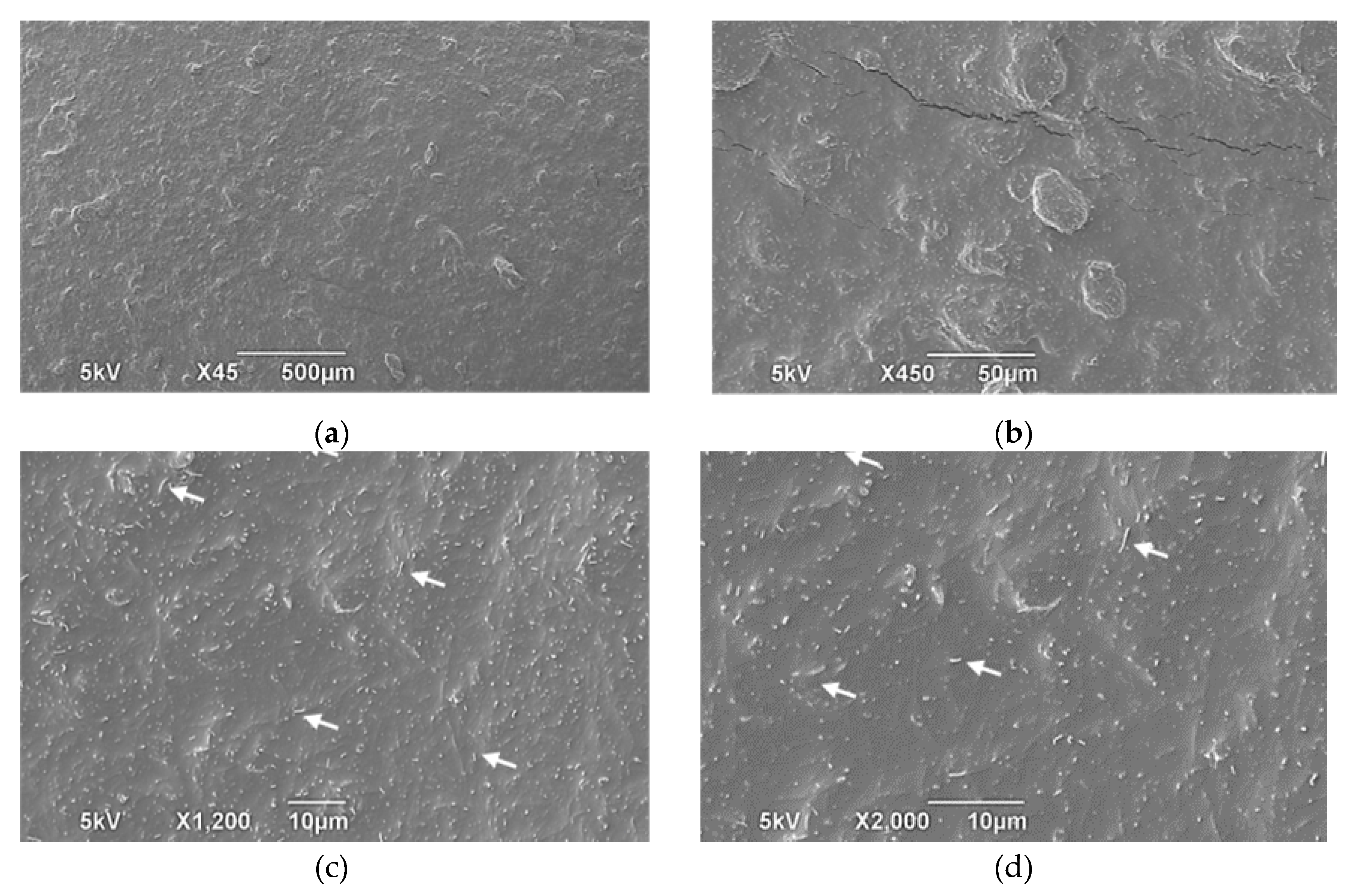
As shown in Figure 2, CNF were exhibited a cylindrical nanostructure. They appeared to be uniformly dispersed in the polymer matrix, thanks to the ultrasonic energy, through a homogeneous coating, as it was already reported in other works that were combining CNF with other polymers and elastomers [28,32,33]. According to Bhawal et al. [33], there could be some voids and agglomerates in such composite structures. The quantity of fillers added to the polymer matrix (12% at most, according to these authors) was linked to them. The voids observed in our study were due to fillers that were added with a concentration of 30%. A mixture of TPU/HIPS made by Cataldi et al. was given this CNF concentration, but the authors failed to mention any of them [38]. However, in their work some voids were seen for a percentage of 30% of GnPs.
Having a large number of fillers has two competitive effects, according to Bhawal et al. [33]. On the one hand, a large number of them contributed to the formation of a dense network and the transport of electrons, ensuring good conductivity. But, on the other hand, despite the assistance of ultrasonic energy, they tended to stack together due to van der Waals energy [33]. In our experiments, mixing at 55 °C appeared to aid in their dispersion. As a result, CNF were able to create a continuous network of interconnected conductive fillers in the polymer matrix. There was some roughness visible, but no cracks or brittle fractures were visible. The SEM images of Figure 2 and Figure S5 appeared to be similar, which is the signature of a reproducible ink.

3.3. Electrical Response under Mechanical Testing

The Mullins effect, which can occur in elastomers during stretching and compression, is characterized by a softening of stress and a decrease in strain recovery after cycles [56,57,58]. This phenomenon indicates that the initial loading path is not fully recovered, providing evidence for the existence of pseudo-elasticity [59]. Previous research has observed the Mullins effect in coated materials [17], suggesting that the mechanical energy released during testing leads to microstructural changes in the coating. These changes facilitate a better connection between conductive fillers, resulting in improved electron transport. In subsequent mechanical tests, the Mullins effect was observed due to the elastomeric substrates. However, further discussion on this topic will not be provided in this study. In this work, two different types of tests were conducted on the Ecoflex substrate covered by the ink. Compression tests were performed to analyze the mechanical behavior of the taxels located in the palm and dorsum of the Hannes hand, while stretching tests were conducted to assess the stretchability and conformity of the ink. In the case of both experiments, a total of 150 cycles were conducted to assess the mechanical properties of the substrates. The detailed results of these tests can be found in the Supporting Information, specifically in Figure S6a,b, which illustrate the behavior of the substrates during compression and stretch-release cycles, respectively. Additionally, Figure S7 provides a visual representation of the 150 compression cycles applied to the taxels. Furthermore, Figure S8a presents the stress/strain curves observed during stretching, while Figure S8b displays the evolution of strain over time.

3.3.1. Compression Cycles

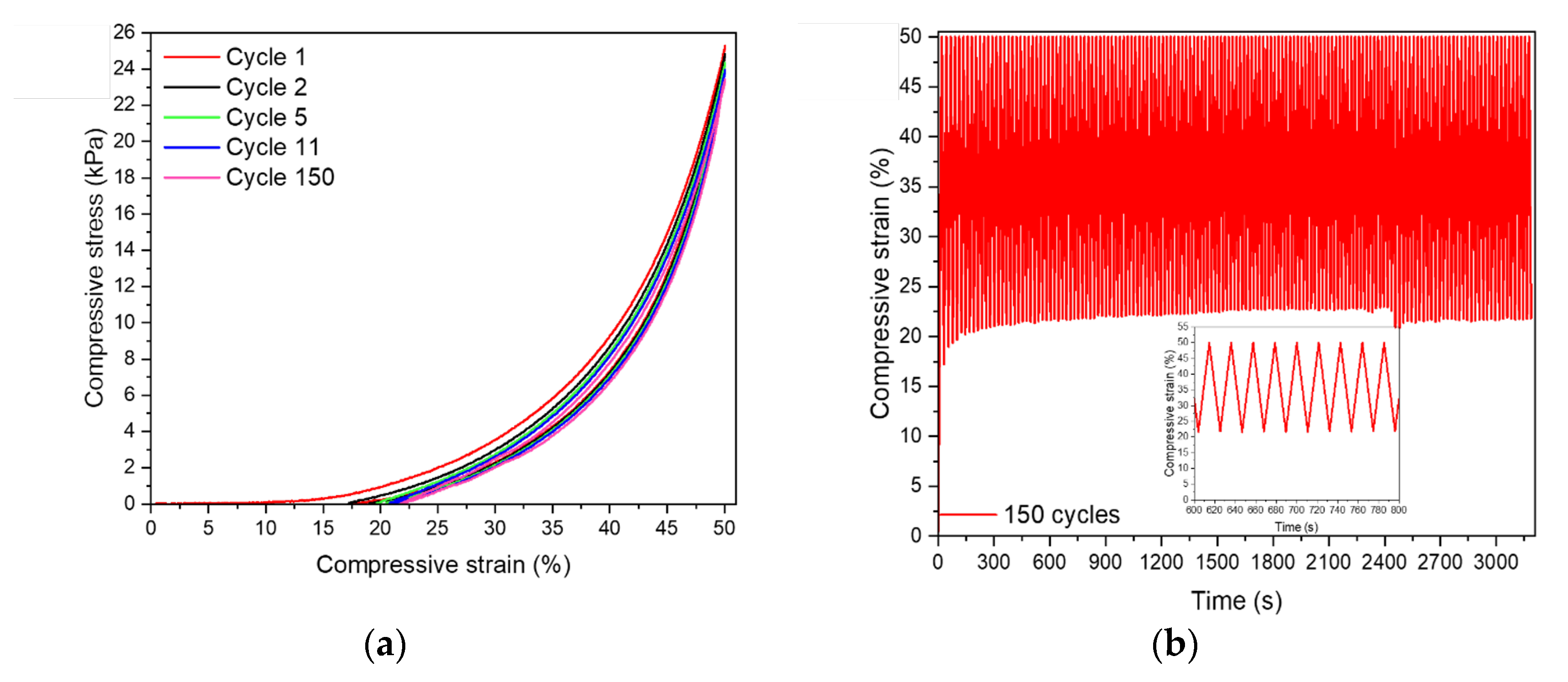
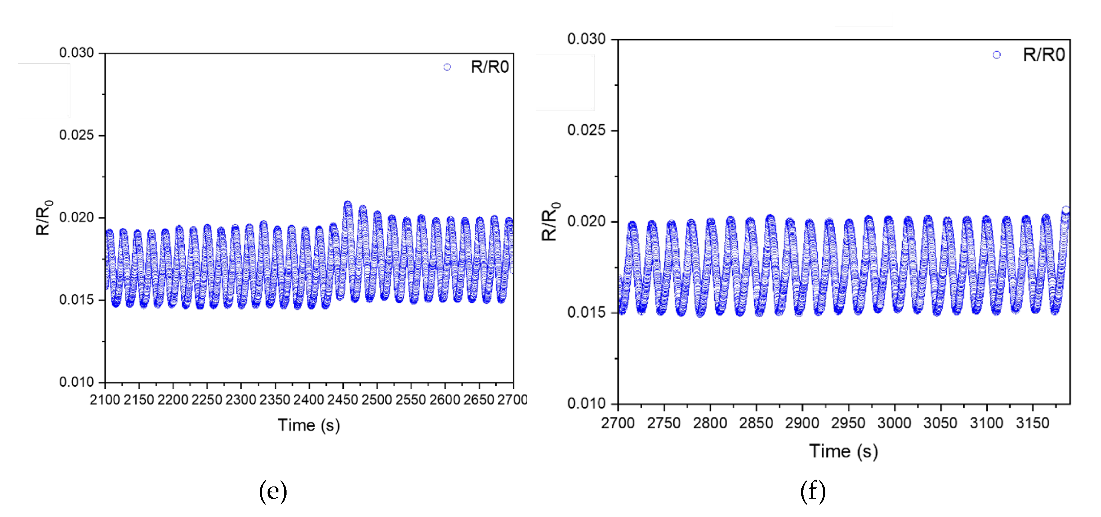
During the compression cycles, the taxels underwent a deformation of up to 50%, and the corresponding electrical signal was recorded simultaneously. The mechanical cycles were illustrated in Figure 3a, while the overall compression strain evolution was depicted in Figure 3b. The high reproducibility of the signal was demonstrated in an insert. For the sake of clarity, only the cycles with visible mechanical changes were presented in the main body of the paper (Figure 3a). The electrical response during the solicitation was further analyzed and presented in several figures (Figure 4a–f) to facilitate comprehension.
The taxels exhibited a similar response during the compression tests, despite the fact that the loading and unloading paths were not overlapped. This observation was further supported by the consistent and reproducible evolution of strain over time throughout the test. The most significant disparity between the loading and unloading paths was observed in the initial cycle, but this difference gradually decreased with subsequent cycles. These findings suggest that the compression tests had no noticeable impact on the taxels. Additionally, the recovery strain experienced a slight increase over the cycles as the stress decreased by a few kPa. The mechanical behavior of the non-coated taxels (Figure S6a) closely resembled that of the coated taxels (Figure 3a). This similarity can be attributed to the conductive layer being sprayed on the bottom of the taxels, causing compression of the truncated cones first, followed by the base, before reaching the conductive layer in the case of the coated sample.
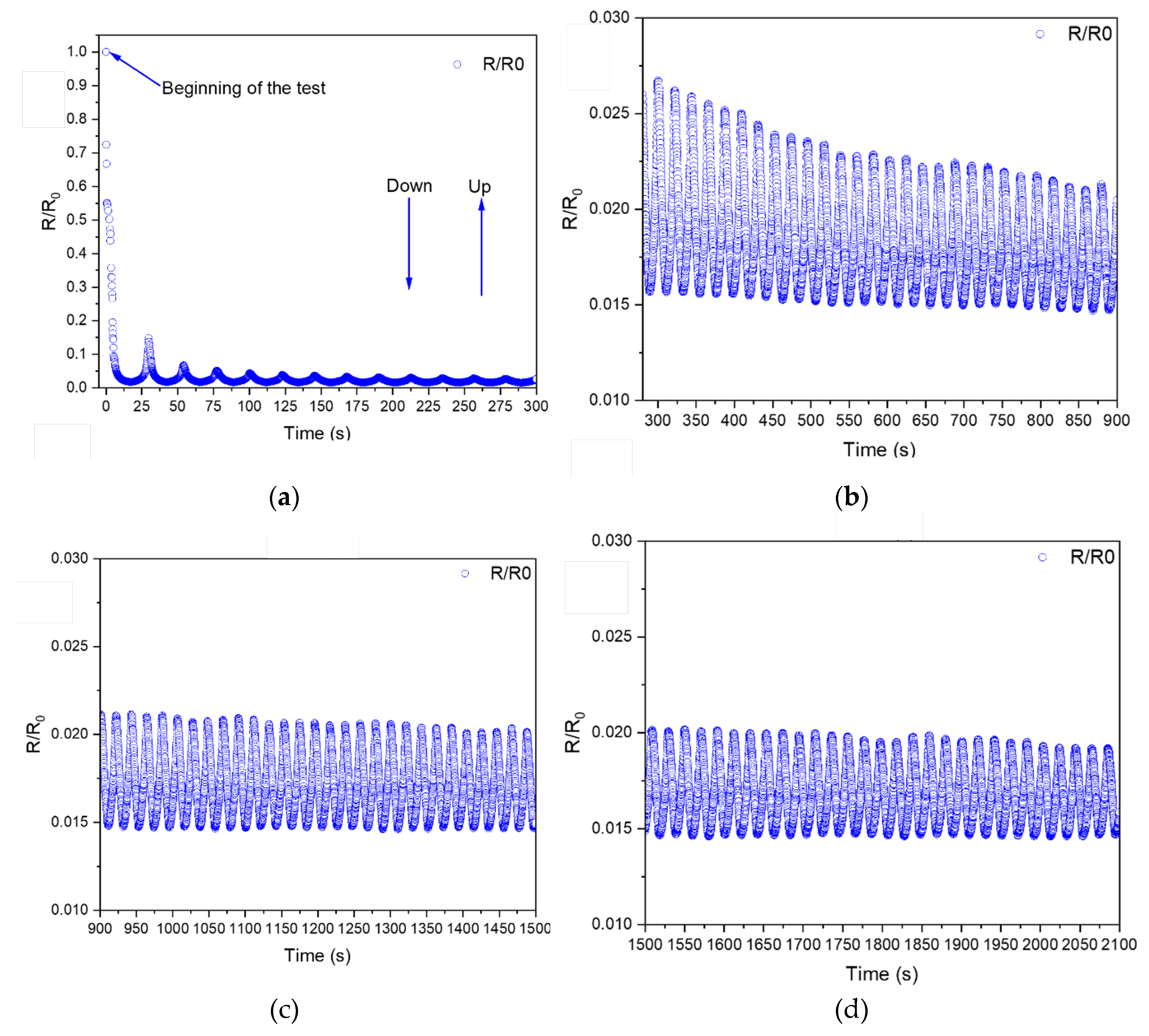
As a result, the mechanical behaviour of both materials is primarily that of Ecoflex. The force measured for the non-coated taxels (Figure S6a) appeared to be slightly higher than the force measured for the coated sample. One explanation could be that the conductive layer (made of a highly deformable elastomer, PVAc-VL) was acting like a protective layer that wasn’t submitted to a lot of deformation and that was absorbing it, while for the sample without coating the deformation reached probably faster the support of the experiment, increasing the strength. During the test, the taxels were compressed resulting in a decrease in the R/R0 ratio (as depicted in Figure 4a). However, during the release, the ratio increased indicating that electron transport was facilitated during the compression step. The amplitude of the electrical behavior was divided by 5 between the first and second cycles. From the second cycle onwards, the electrical behavior decreased and oscillated between 0.020 and 0.015, which corresponded to a reduction of 50 to 70 times. The signal had a triangular shape and was highly reproducible. Despite the coating not being in direct contact with the cell during the cycles, the variation of the R/R0 ratio indicated that the coating was slightly impacted by this solicitation as the cell was initially compressing the truncated cones. The SEM images of the coating after the compressive tests have been reported thereafter in the paper core (Figure 6).

3.3.2. Stretching

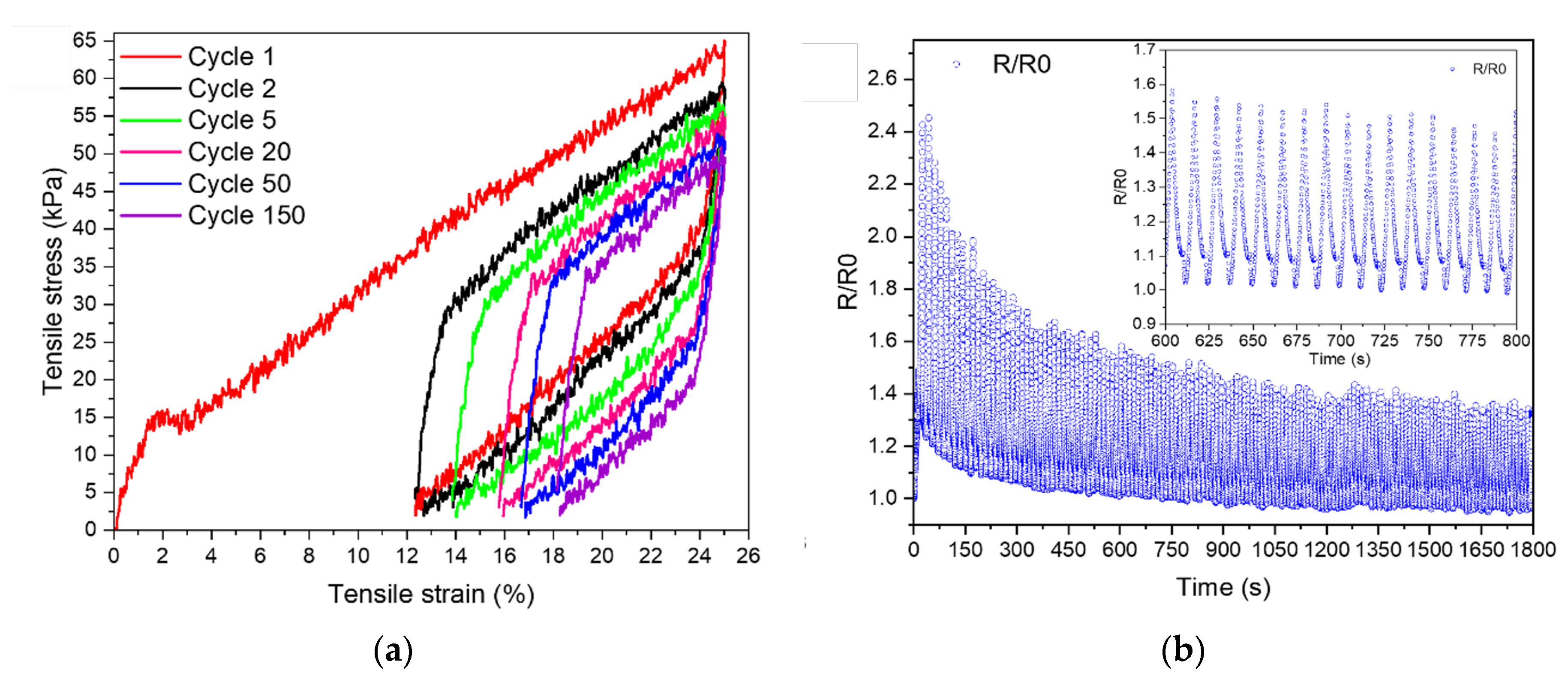
The mechanical behaviour of the stretching test was reported in Figure 5a, while its associated electrical answer was shown in Figure 5b. As for the compression tests, only the cycles where changes were noticeable have been represented.
During stretch-release cycles, the mechanical response of the coated Ecoflex substrate changed progressively. The recovery after the first cycle was around 12%, which was half of the total imposed strain. The strain recovery then decreased gradually, reaching 18% at the end of the 150 cycles. At the same time, the maximum stress was decreasing, as was the loop area. It means that the cycles dissipated less mechanical energy. The strain recovery for the coated sample was lower when compared to the pristine sample (Figure S6b): from 12% to 18% for the coated sample and from 8% to 12% for the pristine one. Moreover, the mechanical response of the pristine sample was not changing from the 8th cycle, while changes were more progressive for the coated sample. The tensile stress of the coated sample (Figure 5a) was twice higher than the one of the pristine (Figure S6b). Additionally, the tensile stress of the coated sample was decreasing more than the one of the pristine substrate. This higher rigidity was mainly due to the presence of the CNF in the coating, as PVAc-VL is a highly stretchable polymer. Then, cycles after cycles the tensile stress decreased as the mechanical energy dissipated by the substrate allowed microstructural changes to occur within the coating. These microstructural changes were responsible of better connection between the CNF and an easier transport of the electron. This observation has already been reported in other works [17,28], and explained the electrical behaviour observed. Indeed, the first stretching was the most damaging one, as the R/R0 ratio is increasing of 2.4 times. Nevertheless, cycles after cycles the R/R0 ratio was decreasing as mechanical energy was dissipated. The same electrical behaviour was observed in the work of Yaragalla et al. [28]. However, the electrical signal exhibited a high level of consistency and had a triangular shape. An insignificant elevation was detected while unloading, likely attributed to the reorganization of the stretched and unloaded CNF during the testing process.

3.3.3. Surface Micro-Morphology of the Coating after Mechanical Solicitation
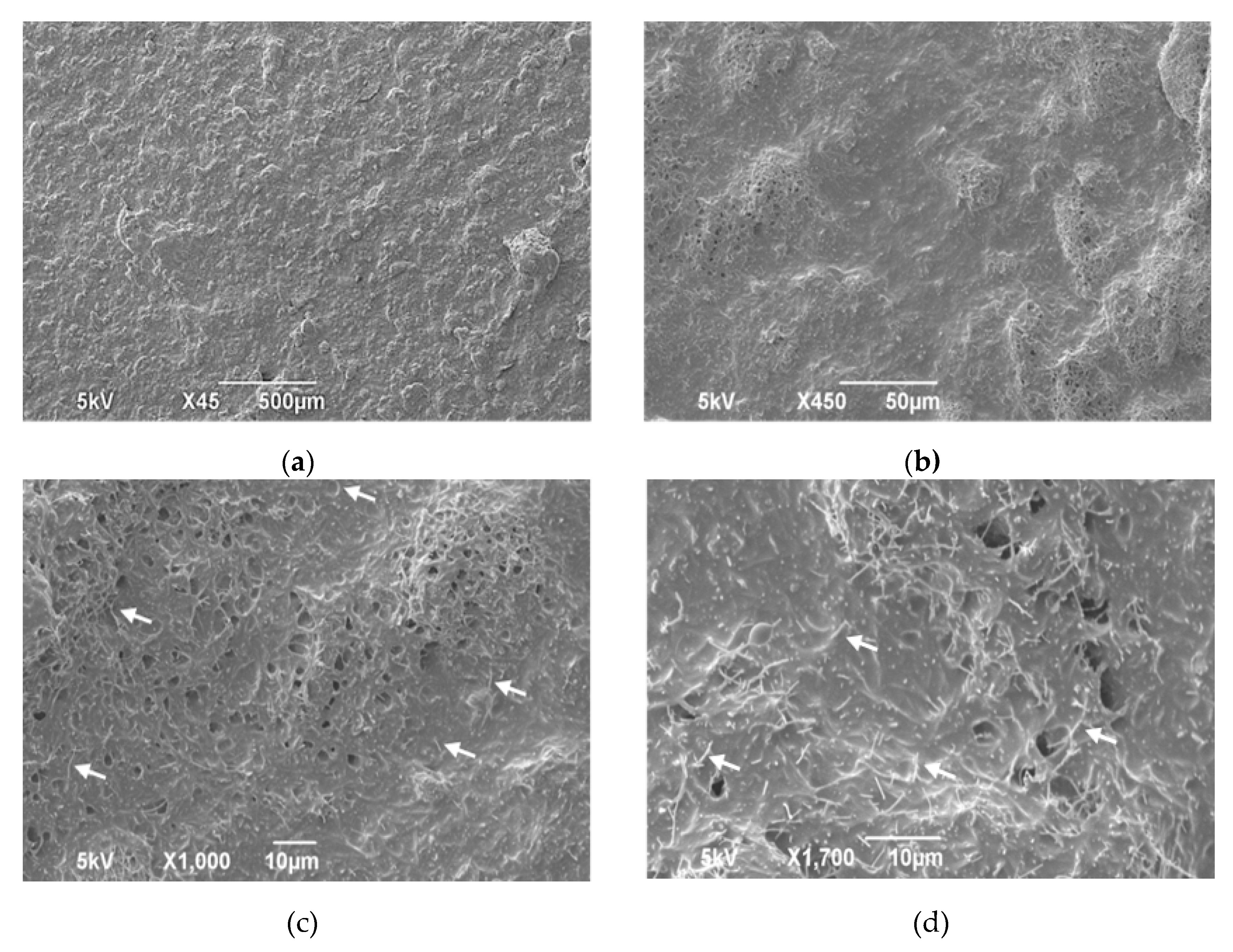
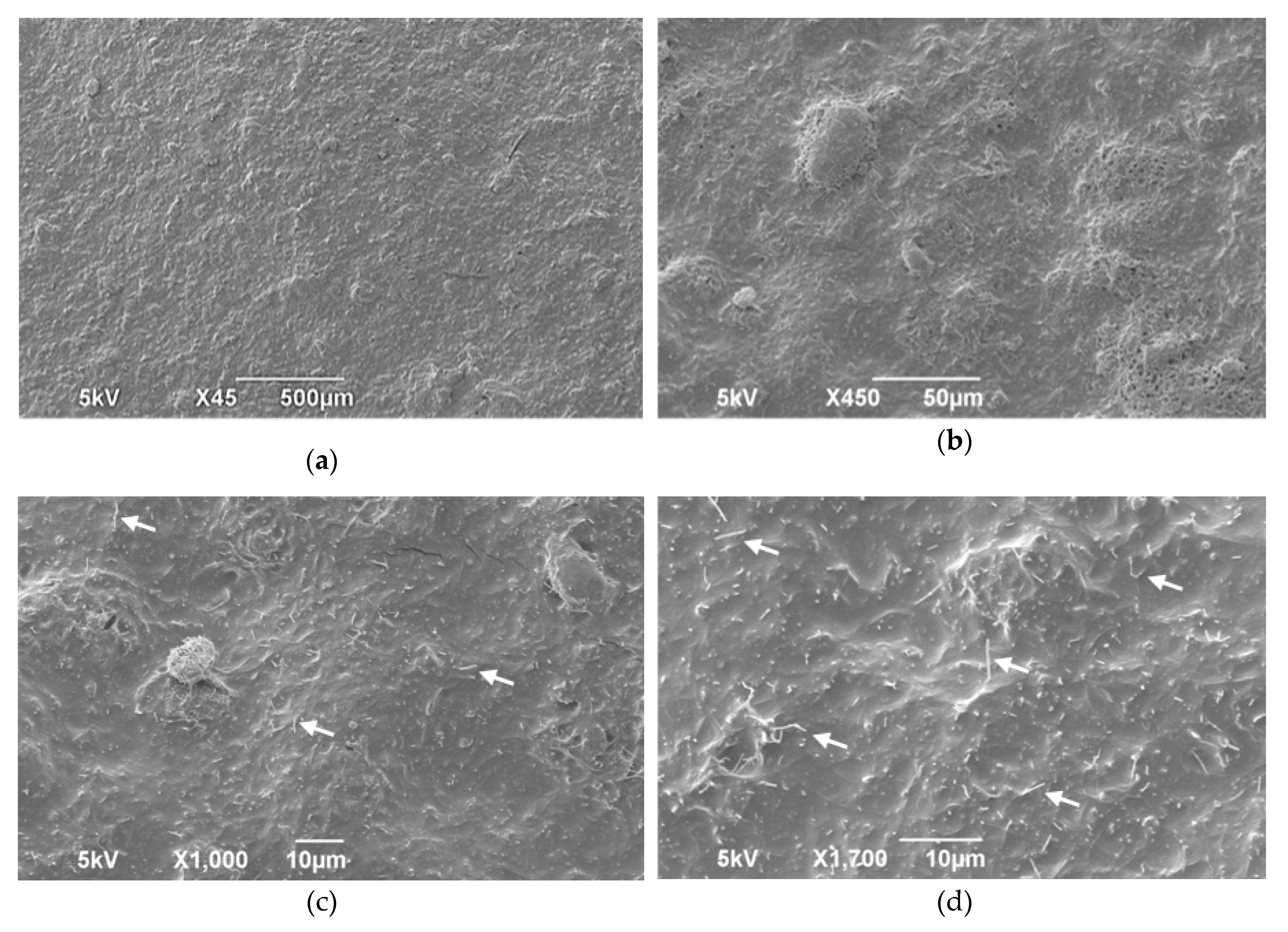
The surface morphology of the coated samples after the compression cycles (Figure 6) and the stretching ones (Figure 7) were added. These images must be compared with those reported before compression (Figure 2) and stretching (Figure S5).
Figure 6. SEM images after the compression cycles at several magnifications. The arrows in images (c) and (d) designate the CNFs dispersed in the polymeric matrix.
Preprints 118018 g006
Figure 7. SEM images after the stretching cycles at several magnifications. White arrows in c) and d) designate CNFs dispersed in the polymeric matrix.
Preprints 118018 g007
The coating remained conformal after both tests. During compression tests, no cracks were developed, and the CNFs were still in contact. There were no discernible differences between Figure 2 and Figure 6. According to Figure 3 and the loop shape, not much mechanical energy was dissipated during compression tests. As a result, the electrical changes were minimal, and there were only a few CNF rearrangements within the coating. Some voids remain after compression, but the CNFs were still connected, as shown in Figure 6d. These void connections were observed after stretching a coating composed of natural rubber and CNF and sprayed on nitrile rubber [28]. CNF tended to remain connected probably due to their geometry and Van der Waals interactions.
On the images acquired after the stretching (Figure 7), some changes were noticeable in comparison with the images obtained before stretching (Figure S5). Few cracks seemed to exist, but they were not impacting the conductivity, as the electrical response was getting better cycles after cycles (Figure 5b). In general, however, the coatings seemed to be smoother, which could be due to the microstructural rearrangement triggered by the mechanical energy dissipated by the substrate. Upon stretching, the area of the loop was much higher than the one of the compression tests and testified that mechanical energy was released and had allowed microstructural changes. As it has been reported in the work of Cataldi and al. [38], after stretching the CNF tended to be oriented less randomly. It appeared to be observable in this work after the strain/stress cycles too, as stretching and unloading were made in the same direction and have aligned the fibers. On the contrary, after compression, the CNF didn’t seem to have been oriented in a certain direction.

3.4. Applications

Hannes' hand contains one of the applications for the presented ink. This prosthetic hand offers biomimetic properties similar to a human hand, including accurate anthropomorphism and human-like grasping behaviour, with the goal of improving patient and social acceptance [60]. It has been designed to be as close to a non-amputee's hand as possible by carefully considering the forms, movements, and orientation of the wrist rotation axes and hand posture [61]. However, no sensing capabilities have been embedded on this medical device at the current development stage, despite the fact that these are critical aspects, as highlighted in [62]. Additionally, another application can be proposed for the iCub humanoid robot, whose size is similar to a young child, and is extensively covered with an electronics skin to enable touch sensing, both on parts of the body (arms, limbs, and chest) and on his hands equipped with sensorial palm and fingertips. The iCub robot can learn and interact with its environment.
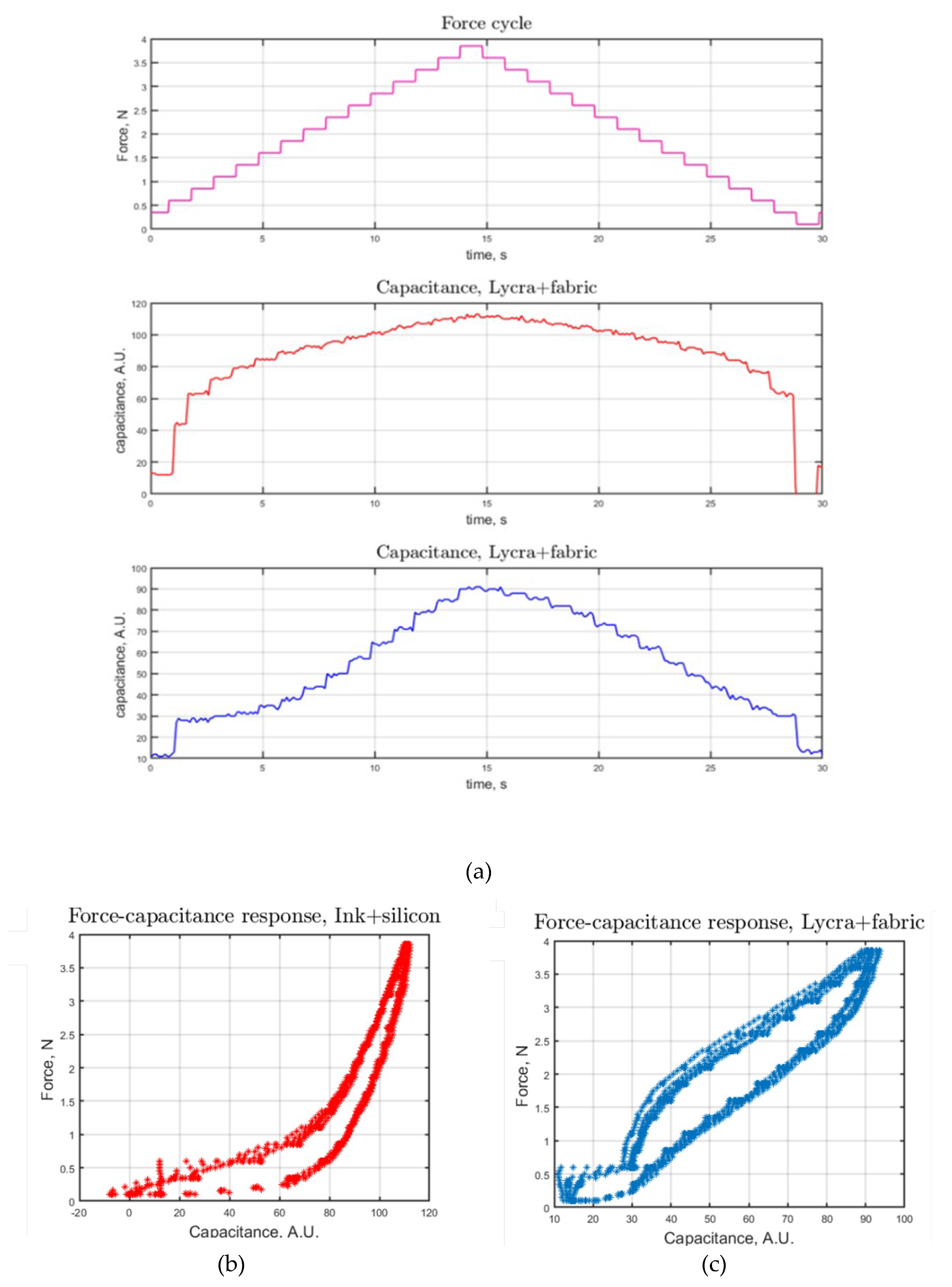
Therefore, the skin patches for both the applications, covered with the proposed conductive ink, can be placed on a PCB with taxels patterned on it. In this way, an array of variable capacitors is formed. By pressing the capacitors, the dielectric is deformed and a capacitance variation between the electrodes builds up: the capacitance changes proportionally to the applied force. We measured the capacitance variation through cycles of increasing and decreasing force applied by means of a haptic device controlled with force feedback [63]. Testing video was added in Supporting Information. The measurement results were shown in Figure 8.
The response of the device we developed was competitive with the standard one that was based on a well-established technological process and can be easily scaled up. Our process promises to be easily scalable also, with an interesting advantage in functionalizing small surfaces like the fingertips or the hand. A more precise characterization was under way on different geometries and will be presented in a following work.

4. Conclusions

An ink formulation was developed using a straightforward procedure and consisted of a biocompatible and biobased copolymer (PVAc-VL) along with conductive nanofillers known as CNF. In accordance with the established protocol, the CNF particles were evenly dispersed within the polymer matrix, resulting in a uniform and conductive coating. Through FTIR analysis, it was observed that certain functional groups within the ink exhibited less restriction compared to those present in the polymer. This disparity could be attributed to the use of a solvent during the ink formulation process, which potentially alleviated some processing limitations. Notably, the degradation rate of the polymer was found to be faster than that of the ink. During testing, no solvent was detected in the ink, indicating that its favorable mechanical properties were primarily attributed to the elastomeric behavior of PVAc-VL and its deformability. Furthermore, the CNF fillers demonstrated stretchability. The conductive ink was successfully applied to various flat substrates to create resistive strain sensors. These sensor samples underwent a series of tests and consistently maintained their conductivity and conformal nature. The R/R0 ratio, which represents the change in resistance relative to the initial resistance, exhibited a gradual decrease with each cycle, particularly after stretching. This phenomenon indicated an improved connection between the CNF particles due to mechanical strain. Additionally, an electronics skin was developed and evaluated for prosthetic and robotics applications. The results demonstrated the device's robustness and responsiveness, affirming its full functionality.

Supplementary Materials

The following supporting information can be downloaded at: www.mdpi.com/xxx/s1, Figure S1: title; Table S1: title; Video S1: title.

Author Contributions

For research articles with several authors, a short paragraph specifying their individual contributions must be provided. The following statements should be used “Conceptualization, E.F. and Y.Y.; methodology, E.F., S.D and I.S.B; validation, I.S.B. and M.M.; E.F.; writing—original draft preparation, E.F, N.B and I.S.B.; writing—review and editing, E.F, I.S.B, M.C, S.D, M.M.; supervision, I.S.B., S.D, M.M; project administration, E.F, I.S.B, M.M,.; funding acquisition, I.S.B, M.M. All authors have read and agreed to the published version of the manuscript.” Please turn to the CRediT taxonomy for the term explanation. Authorship must be limited to those who have contributed substantially to the work reported.

Funding

“This research received no external funding”.

Acknowledgments

This work was supported by the Istituto Nazionale Assicurazione Infortuni sul Lavoro, under grant agreement PR19-PAS-P1. The Open University Affiliated Research Centre at Istituto Italiano di Tecnologia (ARC@IIT) is part of the Open University, Milton Keynes MK7 6AA, United Kingdom.

Conflicts of Interest

Declare conflicts of interest or state “The authors declare no conflicts of interest.” “The funders had no role in the design of the study; in the collection, analyses, or interpretation of data; in the writing of the manuscript; or in the decision to publish the results”.

References

  1. Harmsen, P.F.H.; Hackmann, M.M.; Bos, H.L. Green Building Blocks for Bio-Based Plastics. Biofuels, Bioproducts and Biorefining 2014, 8, 306–324. [CrossRef]
  2. Zhang, N.; Liu, P.; Yi, Y.; Gibril, M.E.; Wang, S.; Kong, F. Application of Polyvinyl Acetate/Lignin Copolymer as Bio-Based Coating Material and Its Effects on Paper Properties. Coatings 2021, Vol. 11, Page 192 2021, 11, 192. [CrossRef]
  3. Liauw, C.M.; Slate, A.J.; Butler, J.A.; Wilson-Nieuwenhuis, J.S.T.; Deisenroth, T.; Preuss, A.; Verran, J.; Whitehead, K.A. The Effect of Surface Hydrophobicity on the Attachment of Fungal Conidia to Substrates of Polyvinyl Acetate and Polyvinyl Alcohol. J Polym Environ 2020, 28, 1450–1464. [CrossRef]
  4. Petković, G.; Vukoje, M.; Bota, J.; Preprotić, S.P. Enhancement of Polyvinyl Acetate (PVAc) Adhesion Performance by SiO2 and TiO2 Nanoparticles. Coatings 2019, 9. [CrossRef]
  5. Silva, M.F.; Pineda, E.A.G.; Hechenleitner, A.A.W.; Fernandes, D.M.; Lima, M.K.; Bittencourt, P.R.S. Characterization of Poly(Vinyl Acetate)/Sugar Cane Bagasse Lignin Blends and Their Photochemical Degradation. J Therm Anal Calorim 2011, 106, 407–413. [CrossRef]
  6. van Acker, F.; Messinger, H.; Bär, A. Evaluation of Vinyl Laurate in a Battery of in Vitro and in Vivo Tests for Genotoxicity. Regulatory Toxicology and Pharmacology 2015, 72, 77–84. [CrossRef]
  7. Lina, B.A.R.; Messinger, H.; Bär, A. 13-Week Oral Toxicity Study of Vinyl Laurate in Rats. Regulatory Toxicology and Pharmacology 2015, 71, 101–107. [CrossRef]
  8. Messinger, H.; Bär, A. Subchronic Toxicity, Toxicity to Reproduction and Prenatal Developmental Toxicity of Vinyl Laurate. Regulatory Toxicology and Pharmacology 2014, 70, 80–86. [CrossRef]
  9. VERSA ® 12 Vinyl Laurate.
  10. Fadda, M.; Contardi, M.; Dante, S.; Di Carlo, M.; Galizzi, G.; Athanassiou, A.; Bayer, I.S. Antioxidant Coatings from Elastomeric Vinyl Acetate-Vinyl Laurate Copolymers with Reduced Bacterial Adhesion. Prog Org Coat 2022, 168, 106883. [CrossRef]
  11. Yu, C.; Choi, K.; Yin, L.; Grunlan, J.C. Light-Weight Flexible Carbon Nanotube Based Organic Composites with Large Thermoelectric Power Factors. ACS Nano 2011, 5, 7885–7892. [CrossRef]
  12. Zgueb, R.; Brichni, A.; Yacoubi, N. Improvement of the Thermal Properties of Sorel Cements by Polyvinyl Acetate: Consequences on Physical and Mechanical Properties. Energy Build 2018, 169, 1–8. [CrossRef]
  13. Shirbhate, N. V.; Yawale, S.P.; Tambakhe, S. V.; Bobade, R.S.; Pakade, S. V. Structural Investigation of Conducting Polythiophene Composites. Journal of Polymer Engineering 2011, 31, 289–292. [CrossRef]
  14. Winterton, N. The Green Solvent: A Critical Perspective. Clean Technologies and Environmental Policy 2021 23:9 2021, 23, 2499–2522. [CrossRef]
  15. Vergaelen, M.; Verbraeken, B.; Van Guyse, J.F.R.; Podevyn, A.; Tigrine, A.; De La Rosa, V.R.; Monnery, B.D.; Hoogenboom, R. Ethyl Acetate as Solvent for the Synthesis of Poly(2-Ethyl-2-Oxazoline). Green Chemistry 2020, 22, 1747–1753. [CrossRef]
  16. Rafiee, H.R.; Sadeghi, S. The Study of Excess Molar Volumes and Related Properties for Binary Mixtures Containing Benzyl Alcohol and 1,3-Dichloro-2-Propanol with Vinyl Acetate, Ethyl Acetate and t-Butyl Acetate at T = 293.15 to 313.15 K and P = 0.087 MPa. Thermochim Acta 2016, 633, 149–160. [CrossRef]
  17. Forestier, E.; Najafi, M.; Dussoni, S.; Maggiali, M.; Athanassiou, A.; Bayer, I.S. Characterization and Performance of Silicone Modified Polylactic Acid (PLA)-Graphene Nanoplatelet Ink Coatings for Flexible Elastomeric Substrates. Prog Org Coat 2023, 174, 107251. [CrossRef]
  18. Yadav, D.; Amini, F.; Ehrmann, A. Recent Advances in Carbon Nanofibers and Their Applications – A Review. Eur Polym J 2020, 138, 109963. [CrossRef]
  19. Huang, X. Fabrication and Properties of Carbon Fibers. Materials 2009, Vol. 2, Pages 2369-2403 2009, 2, 2369–2403. [CrossRef]
  20. Das, T.K.; Ghosh, P.; Das, N.C. Preparation, Development, Outcomes, and Application Versatility of Carbon Fiber-Based Polymer Composites: A Review. Adv Compos Hybrid Mater 2019, 2, 214–233. [CrossRef]
  21. Cheng, H.Y.; Zhu, Y.A.; Sui, Z.J.; Zhou, X.G.; Chen, D. Modeling of Fishbone-Type Carbon Nanofibers with Cone-Helix Structures. Carbon N Y 2012, 50, 4359–4372. [CrossRef]
  22. Hammel, E.; Tang, X.; Trampert, M.; Schmitt, T.; Mauthner, K.; Eder, A.; Pötschke, P. Carbon Nanofibers for Composite Applications. Carbon N Y 2004, 42, 1153–1158. [CrossRef]
  23. Gupta, N.S.; Lee, K.S.; Labouriau, A. Tuning Thermal and Mechanical Properties of Polydimethylsiloxane with Carbon Fibers. Polymers 2021, Vol. 13, Page 1141 2021, 13, 1141. [CrossRef]
  24. Mehrabi, A.; Baheiraei, N.; Adabi, M.; Amirkhani, Z. Development of a Novel Electroactive Cardiac Patch Based on Carbon Nanofibers and Gelatin Encouraging Vascularization. Appl Biochem Biotechnol 2020, 190, 931–948. [CrossRef]
  25. Huang, H.D.; Guo, Z.; Yang, P. yan; Chen, P.; Wu, J. Electrical Conductivity and Hydrophobicity of Graphene Oxide-Modified Carbon Nanofibers. Chem Phys Lett 2021, 771, 138551. [CrossRef]
  26. Sui, G.; Jana, S.; Zhong, W.H.; Fuqua, M.A.; Ulven, C.A. Dielectric Properties and Conductivity of Carbon Nanofiber/Semi-Crystalline Polymer Composites. Acta Mater 2008, 56, 2381–2388. [CrossRef]
  27. Sharma, M.; Gao, S.; Mäder, E.; Sharma, H.; Wei, L.Y.; Bijwe, J. Carbon Fiber Surfaces and Composite Interphases. Compos Sci Technol 2014, 102, 35–50. [CrossRef]
  28. Yaragalla, S.; Dussoni, S.; Zahid, M.; Maggiali, M.; Metta, G.; Athanasiou, A.; Bayer, I.S. Stretchable Graphene and Carbon Nanofiber Capacitive Touch Sensors for Robotic Skin Applications. Journal of Industrial and Engineering Chemistry 2021. [CrossRef]
  29. Newcomb, B.A. Processing, Structure, and Properties of Carbon Fibers. Compos Part A Appl Sci Manuf 2016, 91, 262–282. [CrossRef]
  30. Torris, A.; Badiger, M. V. Polysaccharide Hydrogel Incorporated Carbon Nanofiber Microelectrode for Designing Neural Interfaces. J Bionic Eng 2019, 16, 696–710. [CrossRef]
  31. Jung, H.; Kwon, D.; Lee, S.A.; Kim, Y.J.; Ahn, J.W. Carbon Nanofiber-Based Wearable Patches for Bio-Potential Monitoring. J Med Biol Eng 2019, 39, 892–900. [CrossRef]
  32. Wu, H.; Sun, H.; Han, F.; Xie, P.; Zhong, Y.; Quan, B.; Zhao, Y.; Liu, C.; Fan, R.; Guo, Z. Negative Permittivity Behavior in Flexible Carbon Nanofibers-Polydimethylsiloxane Films. Engineered Science 2022, 17, 113–120. [CrossRef]
  33. Bhawal, P.; Ganguly, S.; Das, T.K.; Mondal, S.; Nayak, L.; Das, N.C. A Comparative Study of Physico-Mechanical and Electrical Properties of Polymer-Carbon Nanofiber in Wet and Melt Mixing Methods. Mater Sci Eng B Solid State Mater Adv Technol 2019, 245, 95–106. [CrossRef]
  34. Xu, Y.; Higgins, B.; Brittain, W.J. Bottom-up Synthesis of PS–CNF Nanocomposites. Polymer (Guildf) 2005, 46, 799–810. [CrossRef]
  35. Kumar, S.; Rath, T.; Mahaling, R.N.; Reddy, C.S.; Das, C.K.; Pandey, K.N.; Srivastava, R.B.; Yadaw, S.B. Study on Mechanical, Morphological and Electrical Properties of Carbon Nanofiber/Polyetherimide Composites. Materials Science and Engineering: B 2007, 141, 61–70. [CrossRef]
  36. Ma, H.; Zeng, J.; Realff, M.L.; Kumar, S.; Schiraldi, D.A. Processing, Structure, and Properties of Fibers from Polyester/Carbon Nanofiber Composites. Compos Sci Technol 2003, 63, 1617–1628. [CrossRef]
  37. Tibbetts, G.G.; McHugh, J.J. Mechanical Properties of Vapor-Grown Carbon Fiber Composites with Thermoplastic Matrices. J Mater Res 1999, 14, 2871–2880. [CrossRef]
  38. Cataldi, P.; Dussoni, S.; Ceseracciu, L.; Maggiali, M.; Natale, L.; Metta, G.; Athanassiou, A.; Bayer, I.S. Carbon Nanofiber versus Graphene-Based Stretchable Capacitive Touch Sensors for Artificial Electronic Skin. Advanced Science 2018, 5, 1700587. [CrossRef]
  39. Cataldi, P.; Steiner, P.; Raine, T.; Lin, K.; Kocabas, C.; Young, R.J.; Bissett, M.; Kinloch, I.A.; Papageorgiou, D.G. Multifunctional Biocomposites Based on Polyhydroxyalkanoate and Graphene/Carbon Nanofiber Hybrids for Electrical and Thermal Applications. ACS Appl Polym Mater 2020, 2, 3525–3534. [CrossRef]
  40. Guo, Z.; Long, B.; Gao, S.; Luo, J.; Wang, L.; Huang, X.; Wang, D.; Xue, H.; Gao, J. Carbon Nanofiber Based Superhydrophobic Foam Composite for High Performance Oil/Water Separation. J Hazard Mater 2021, 402, 123838. [CrossRef]
  41. Slipher, G.A.; David Hairston, W.; Cortney Bradford, J.; Bain, E.D.; Mrozek, R.A. Carbon Nanofiber-Filled Conductive Silicone Elastomers as Soft, Dry Bioelectronic Interfaces. PLoS One 2018, 13, e0189415. [CrossRef]
  42. Rennhofer, H.; Zanghellini, B. Dispersion State and Damage of Carbon Nanotubes and Carbon Nanofibers by Ultrasonic Dispersion: A Review. Nanomaterials 2021, Vol. 11, Page 1469 2021, 11, 1469. [CrossRef]
  43. Hsu, L.; Weder, C.; Rowan, S.J. Stimuli-Responsive, Mechanically-Adaptive Polymer Nanocomposites. J Mater Chem 2011, 21, 2812–2822. [CrossRef]
  44. Souri, H.; Bhattacharyya, D. Wearable Strain Sensors Based on Electrically Conductive Natural Fiber Yarns. Mater Des 2018, 154, 217–227. [CrossRef]
  45. Devaraj, H.; Giffney, T.; Petit, A.; Assadian, M.; Aw, K. The Development of Highly Flexible Stretch Sensors for a Robotic Hand. Robotics 2018, 7. [CrossRef]
  46. Ying, B.; Chen, R.Z.; Zuo, R.; Li, J.; Liu, X. An Anti-Freezing, Ambient-Stable and Highly Stretchable Ionic Skin with Strong Surface Adhesion for Wearable Sensing and Soft Robotics. Adv Funct Mater 2021, 31, 2104665. [CrossRef]
  47. Chen, H.; Wang, F.; Chen, H.; Fang, H. Da; Feng, W.; Wei, Y.; Wang, F.F.; Su, H.L.; Mi, Y.D.; Zhou, M.; et al. Specific Biotests to Assess Eco-Toxicity of Biodegradable Polymer Materials in Soil. J Environ Sci (China) 2021, 105, 150–162. [CrossRef]
  48. Rosa, D.S.; Grillo, D.; Bardi, M.A.G.; Calil, M.R.; Guedes, C.G.F.; Ramires, E.C.; Frollini, E. Mechanical, Thermal and Morphological Characterization of Polypropylene/Biodegradable Polyester Blends with Additives. Polym Test 2009, 28, 836–842. [CrossRef]
  49. Witt, U.; Einig, T.; Yamamoto, M.; Kleeberg, I.; Deckwer, W.D.; Müller, R.J. Biodegradation of Aliphatic–Aromatic Copolyesters: Evaluation of the Final Biodegradability and Ecotoxicological Impact of Degradation Intermediates. Chemosphere 2001, 44, 289–299. [CrossRef]
  50. Han, F.; Li, M.; Ye, H.; Zhang, G. Materials, Electrical Performance, Mechanisms, Applications, and Manufacturing Approaches for Flexible Strain Sensors. Nanomaterials 2021, 11.
  51. Amjadi, M.; Kyung, K.-U.; Park, I.; Sitti, M.; Amjadi, M.; Sitti, M.; Kyung, K.; Park, I. Stretchable, Skin-Mountable, and Wearable Strain Sensors and Their Potential Applications: A Review. Adv Funct Mater 2016, 26, 1678–1698. [CrossRef]
  52. Han, S.T.; Peng, H.; Sun, Q.; Venkatesh, S.; Chung, K.S.; Lau, S.C.; Zhou, Y.; Roy, V.A.L. An Overview of the Development of Flexible Sensors. Advanced Materials 2017, 29, 1700375. [CrossRef]
  53. Maiolino, P.; Maggiali, M.; Cannata, G.; Metta, G.; Natale, L. A Flexible and Robust Large Scale Capacitive Tactile System for Robots. IEEE Sens J 2013, 13, 3910–3917. [CrossRef]
  54. Araby, S.; Meng, Q.; Zhang, L.; Kang, H.; Majewski, P.; Tang, Y.; Ma, J. Electrically and Thermally Conductive Elastomer/Graphene Nanocomposites by Solution Mixing. Polymer (Guildf) 2014, 55, 201–210.
  55. Saidina, D.S.; Eawwiboonthanakit, N.; Mariatti, M.; Fontana, S.; Hérold, C. Recent Development of Graphene-Based Ink and Other Conductive Material-Based Inks for Flexible Electronics. Journal of Electronic Materials 2019 48:6 2019, 48, 3428–3450. [CrossRef]
  56. Rickaby, S.R.; Scott, N.H. Cyclic Stress-Softening Model for the Mullins Effect in Compression. Int J Non Linear Mech 2013, 49, 152–158. [CrossRef]
  57. Mullins, L. Effect of Stretching on the Properties of Rubber. Rubber Chemistry and Technology 1948, 21, 281–300. [CrossRef]
  58. Mullins, L. Softening of Rubber by Deformation. Rubber Chemistry and Technology 1969, 42, 339–362. [CrossRef]
  59. Dorfmann, A.; Ogden, R.W. A Constitutive Model for the Mullins Effect with Permanent Set in Particle-Reinforced Rubber. Int J Solids Struct 2004, 41, 1855–1878. [CrossRef]
  60. Laffranchi, M.; Boccardo, N.; Traverso, S.; Lombardi, L.; Canepa, M.; Lince, A.; Semprini, M.; Saglia, J.A.; Naceri, A.; Sacchetti, R.; et al. The Hannes Hand Prosthesis Replicates the Key Biological Properties of the Human Hand. Sci Robot 2020, 5. [CrossRef]
  61. Caserta, G.; Boccardo, N.; Freddolini, M.; Barresi, G.; Marinelli, A.; Canepa, M.; Stedman, S.; Lombardi, L.; Laffranchi, M.; Gruppioni, E.; et al. Benefits of the Cybathlon 2020 Experience for a Prosthetic Hand User: A Case Study on the Hannes System. J Neuroeng Rehabil 2022, 19, 1–15. [CrossRef]
  62. Marinelli, A.; Boccardo, N.; Tessari, F.; Di Domenico, D.; Caserta, G.; Canepa, M.; Gini, G.; Barresi, G.; Laffranchi, M.; De Michieli, L.; et al. Active Upper Limb Prostheses: A Review on Current State and Upcoming Breakthroughs. Progress in Biomedical Engineering 2023, 5, 012001. [CrossRef]
  63. Jamali, N.; Maggiali, M.; Giovannini, F.; Metta, G.; Natale, L. A New Design of a Fingertip for the ICub Hand. IEEE International Conference on Intelligent Robots and Systems 2015, 2015-December, 2705–2710. [CrossRef]
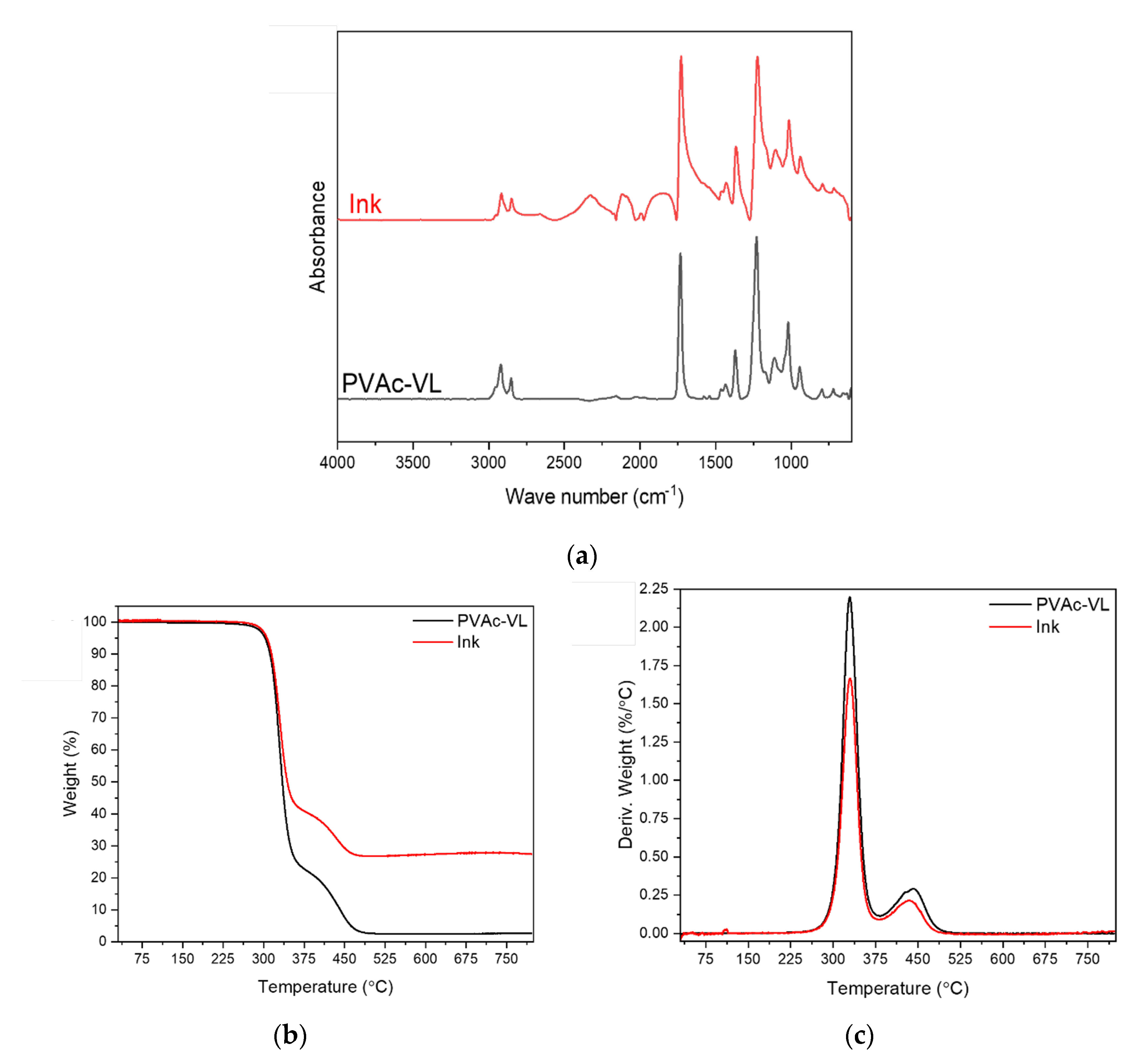
Figure 1. FTIR spectrum of PVAc-VL (bottom, in black) and of the ink (top, red), (b) mass loss and (c) derivatives of the TGA thermograms of PVAc-VL (black) and of the ink (red).
Preprints 118018 g001
Figure 2. Surface morphology of the ink sprayed on the Ecoflex substrate before the compression tests. The arrows in images (c) and (d) designate the CNFs dispersed in the polymeric matrix.
Preprints 118018 g002
Figure 3. (a) Mechanical behaviour during compression cycles, (b) evolution of the compressive strain over time, a zoom was made in insert.
Preprints 118018 g003
Figure 4. (a) to (f) Details of the evolution of the R/R0 ratio upon compression tests.
Preprints 118018 g004aPreprints 118018 g004b
Figure 5. (a) Stress/strain curves during stretching and (b) associated electrical evolution.
Preprints 118018 g005
Figure 8. This is a figure. Schemes follow another format. If there are multiple panels, they should be listed as: (a) Description of what is contained in the first panel; (b) Description of what is contained in the second panel. Figures should be placed in the main text near to the first time they are cited.
Preprints 118018 g008
Table 1. Shifted wave numbers between the ink and PVAc-VL with the associated chemical groups.
Wave Number (ink)
(cm-1)
Wave Number (PVAc-VL)
(cm-1)
Groups Associated
1103 1109 C-O stretching vibration
1221 1227 C-O asymmetric stretching
1364 1371 CH3 symmetric bending
1728 1731 C=O stretching
2850 2852 C-H symmetric stretching
Disclaimer/Publisher’s Note: The statements, opinions and data contained in all publications are solely those of the individual author(s) and contributor(s) and not of MDPI and/or the editor(s). MDPI and/or the editor(s) disclaim responsibility for any injury to people or property resulting from any ideas, methods, instructions or products referred to in the content.
Copyright: This open access article is published under a Creative Commons CC BY 4.0 license, which permit the free download, distribution, and reuse, provided that the author and preprint are cited in any reuse.
Prerpints.org logo

Preprints.org is a free preprint server supported by MDPI in Basel, Switzerland.

Subscribe

© 2024 MDPI (Basel, Switzerland) unless otherwise stated