1. Introduction
The existing low-frequency spectrum resources have become saturated, and higher-frequency terahertz waves undoubtedly have great application prospects. The frequency of terahertz waves is 0.1~10 THz, and the band is between microwaves and far-infrared light. It can be considered that terahertz waves are in the transition zone from macroscopic classical theory to microscopic quantum theory. Since the wavelength of terahertz waves is close to the visible light region and its penetrating ability is stronger than that of visible light, optical methods can be used to design dielectric lenses with reasonable structure and size to focus terahertz waves[
1,
2,
3,
4].
In current research on terahertz transmission systems, dielectric lenses widely used on transmitters and receivers are typically conventional plano-convex lenses[
5,
6,
7,
8,
9,
10,
11,
12]. The design of plano-convex lenses is generally based on the ray-tracing method in geometric optics, where the feed source is typically positioned to coincide with the focal point. In this design approach, the curvature of the lens is usually determined using Fermat's principle and Snell's law. Plano-convex lenses have become widely adopted optical components in terahertz transmission systems due to their stable focusing capability, wide field of view, and good multi-frequency applicability. In practice, even when there is some angular deviation between the direction of the received signal and the lens surface, plano-convex lenses can still maintain a high gain performance. Additionally, the design of plano-convex lenses is straightforward, and the manufacturing technology is well-established, with design schemes based on geometric optics being particularly mature. Consequently, plano-convex lenses are extensively used in current research on terahertz transmission systems to enhance antenna gain and directivity, thereby facilitating long-distance signal transmission[
13,
14,
15,
16,
17,
18,
19,
20,
21].
In the literature[
7], a research team from Fudan University established a long-distance terahertz signal transmission system that achieved a transmission distance of 850 meters. During the experiment, the researchers installed a plano-convex lens with a diameter of 10 cm in front of the transmitting antenna to correct phase and collimate the electromagnetic beam, while another plano-convex lens with a diameter of 30 cm was placed in front of the receiving antenna to focus the electromagnetic beam. The experimental results indicated that the gain of the lens antennas reached 48.5dBi and 65dBi, respectively. Furthermore, other studies have also demonstrated the critical role of PTFE lenses in long-distance terahertz wireless transmission, with the lens gains at both the transmitter and receiver reaching 70dB[
10,
22]. These findings underscore the indispensable role of high-gain dielectric lenses in long-distance terahertz transmission systems.
As the transmission distance increases, terahertz signals experience greater atmospheric losses and free-space path losses during propagation, necessitating higher gain for lens antennas. Typically, assuming structural losses are negligible, doubling the effective aperture of a plano-convex lens results in an approximate 6 dB increase in antenna gain. Therefore, in long-distance terahertz transmission, increasing the aperture of the lens antenna becomes a key method for enhancing antenna gain. However, in practice, as the aperture size increases, the volume and weight of the plano-convex lens also increase significantly. Additionally, due to the inverse relationship between the lens focal length and thickness, achieving a balance with short focal length large-aperture lenses in engineering practice presents considerable challenges[
13,
14,
15].
To address the aforementioned challenges, we propose a novel terahertz lens antenna design—the Fresnel lens. The Fresnel lens consists of a series of concentric prisms etched onto the lens's base surface, making it lighter and thinner compared to traditional plano-convex lenses. This characteristic allows the Fresnel lens to maintain a reduced thickness and mass even in scenarios involving large apertures and short focal lengths, thereby helping to minimize material absorption losses and facilitating easier engineering deployment and installation[
23,
24].
The Fresnel lens, as an important optical component, has been widely applied across various fields. Owing to its unique structural design, the Fresnel lens can significantly reduce both the thickness and weight of the lens while maintaining optical performance, making it particularly advantageous for use in portable devices. For instance, in solar concentrators, Fresnel lenses focus parallel light onto a small area, enhancing energy capture efficiency. In lighting systems, Fresnel lenses are extensively used in lamps and automotive headlights to achieve efficient optical designs. Additionally, in photography and projection, Fresnel lenses are employed as light-focusing and diffusing devices due to their lightweight nature and cost-effectiveness. These diverse applications underscore the indispensable role of Fresnel lenses in modern optical systems, highlighting their significant academic and engineering value[
25,
26,
27,
28,
29].
In this study, we have designed a Fresnel lens operating in the terahertz frequency band for the first time and successfully validated its performance within a terahertz wireless transmission system. We employed geometric optics methods to design the Fresnel lens, precisely calculating its parameters based on Snell's law, and conducted thorough ray-tracing analyses using optical software. Through comparative simulations, we found that although the electromagnetic beam focusing ability of the Fresnel lens is slightly lower than that of traditional plano-convex lenses, it offers a shorter focal length and lighter weight, making it particularly advantageous in large-aperture applications. In practical validation within a terahertz wireless transmission system, the Fresnel lens demonstrated significant potential. This design offers a promising research direction for the development of high-gain terahertz lens antennas in the future.
The remainder of this paper is organized as follows:
Section 2 provides a brief overview of the relevant theory of Fresnel lenses, followed by design analysis and simulation.
Section 3 discusses the performance and actual gain of the fabricated Fresnel lens within a terahertz wireless communication system.
Section 4 presents the results and conclusions of this work.
2. Theory and Simulation
2.1. Approximate Treatment of Geometric Optics
As mentioned earlier, the terahertz frequency band is close to the visible light region, allowing it to be approximated using geometric optics[
30]. The following provides a proof of this approximation. Consider a general time-harmonic field in an isotropic non-conductive medium:
The refractive index of the medium is
,
is the relative dielectric constant, and
is the relative magnetic permeability. Where
and
represent the complex vector function of the position. In the passive region, without considering the time factor, the above vectors satisfy Maxwell's equations:
Where,
,
is the vacuum wavelength. Considering:
Evidently,
and
are vector functions of position, representing the amplitude.
is a real scalar function of position, representing the phase function of the propagating wave.
Similarly, by substituting
and
into the Maxwell's equations, we obtain:
Let's consider the magnitude of
. In the terahertz frequency range, as well as in the visible light spectrum, the electromagnetic field is characterized by relatively fast oscillations (with frequencies on the order of 10¹²Hz and above), or in other words, relatively short wavelengths (on the order of 10⁻³ cm and below). Therefore, it can be expected that under such circumstances, ignoring the finite size of the wavelength can provide a good first-order approximation of the wave propagation laws. In traditional optical research, it is common practice to ignore the wavelength, i.e.,
. This branch of study is typically referred to as geometric optics because, under this approximation, the laws of wave propagation can be described using geometric language. In this case, the energy of the electromagnetic field can be considered to be transmitted along certain curves (rays). For issues related to the terahertz frequency range, such an approach remains suitable. Additionally, since the size of the lens antenna we designed is much larger than the wavelength in free space, diffraction effects can be ignored to some extent. Therefore, it is effective to use the assumptions of geometric optics to design these lens antennas. Thus, when
,
, and we can omit all product terms on the right side of the equation.
Evidently, by taking the dot product of
with the first two equations, the last two equations can be derived. Therefore, by directly combining the first two equations and substituting the refractive index, we obtain:
Further transformation yields:
This is the fundamental equation of geometric optics: the eikonal equation, where is called the eikonal, is the refractive index in space, and represents the phase gradient (i.e., the direction of the light rays). In an isotropic homogeneous medium, the refractive index does not vary with position, so is constant.
The eikonal equation indicates that, under the geometric optics approximation, the propagation path of light rays is determined by the gradient of the phase function
. Specifically, light rays always travel in the direction where the phase changes most rapidly, which is consistent with Fermat's principle: light always chooses the path with the shortest optical length when traveling between two points. From Fermat's principle, the fundamental laws of reflection and refraction in geometric optics can be derived[
30,
31,
32].
2.2. The Principle of the Fresnel Lens
The Fresnel lens is an evolution based on the plano-convex lens (or aspheric lens). In traditional geometric optics, light rays are refracted at the surface where different media meet, altering their direction of propagation. Therefore, the contour of the refractive surface of a traditional lens largely determines it focusing ability, while the material between the refractive surfaces does not change the direction of light propagation but instead significantly increases material absorption losses and weight[
33,
34,
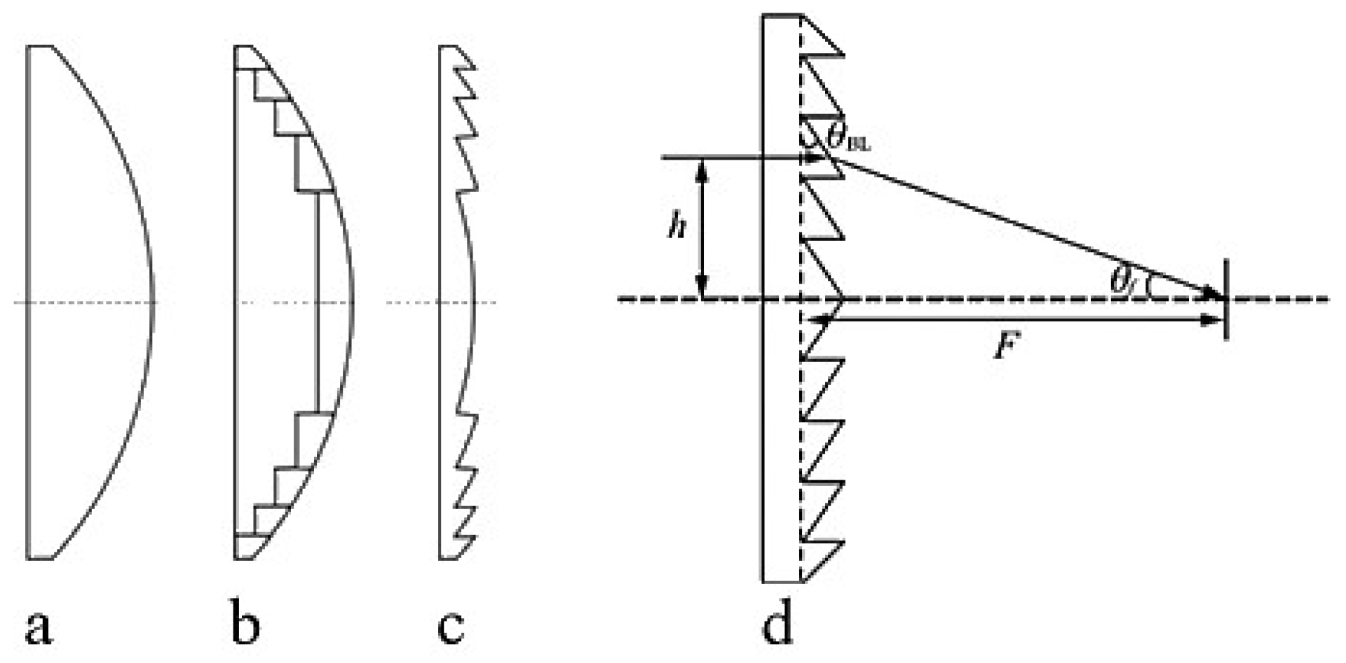
35]. Essentially, the Fresnel lens removes the portions of the original lens that do not affect the curvature of the lens, retaining only the parts that effectively refract light, as illustrated in
Figure 1.
In engineering practice, considering the challenges of design and manufacturing, the annular surfaces of a Fresnel lens are generally not curved but conical. The base of the lens is composed of a series of concentric rings, and from a cross-sectional view, each ring can be considered a small prism with a different tilt angle. Therefore, this design method is also known as the prism method[
35,
36,
37]. The terahertz waves refracted by the ring surfaces are focused on the focal point, and the focus position of the lens can be adjusted by changing the tilt angle of the rings. As shown in
Figure 1d, the refraction of a single annular ring is considered. Let
be the height of the incident light,
the angle of the lens ring,
the angle between the refracted light and the optical axis, and
the focal length of the lens. According to the law of refraction, the following relationship can be derived:
The angle of each ring and its distance from the center of the lens can be calculated through iterative optimization. In this study, mature optical design software is used for the design process, allowing for weighted optimization of multiple parameters.
2.3. The Structural Loss and Frequency Dependence of the Fresnel Lens
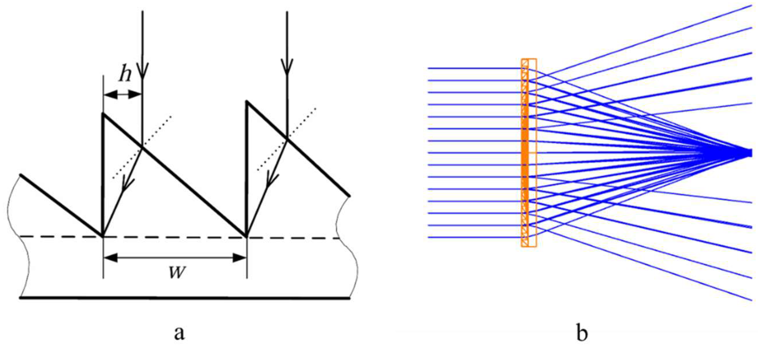
As shown in
Figure 2(a), for a Fresnel lens, when light rays are incident on the surface of the lens rings, they are refracted, but at the edges of each ring, some rays are blocked and cannot reach the designated focal point, resulting in structural loss. Let the tooth width of the lens ring be
, and within the annular region of width
for that ring, the incident light rays are obstructed by the side surfaces (non-working surfaces) of the lens ring, preventing them from converging on the focal plane. Instead, they scatter, forming off-axis rays, as illustrated in
Figure 2(b). At this point, the structural loss rate for the ring is
. Clearly, this type of structural loss is unavoidable. Generally, the wider the lens ring section (i.e., the larger
), the weaker the scattering effect.
The above equation is the Sellmeier dispersion formula, where and are material-dependent constants, is the wavelength, and is the refractive index. From Equation (9), it is clear that the refractive index is a crucial parameter in lens structure design. According to the Sellmeier equation, in the same medium, the refractive index varies with different wavelengths of light. The refractive index typically decreases as the wavelength increases, reflecting the dispersion characteristics of the material—meaning that light of different wavelengths travels at different speeds in the material, leading to dispersion effects. Another significant impact of the dispersion effect on the Fresnel lens is its frequency sensitivity. The refractive surface of a plano-convex lens is a smooth curve, and its design is considered as a whole. However, the Fresnel lens is designed through sectional optimization, meaning that the parameters of the lens rings are determined based on the design wavelength. For slightly different wavelengths, these parameters become inaccurate. Generally, the bandwidth of the lens is inversely related to the number of rings.
2.4. Design and Simulation
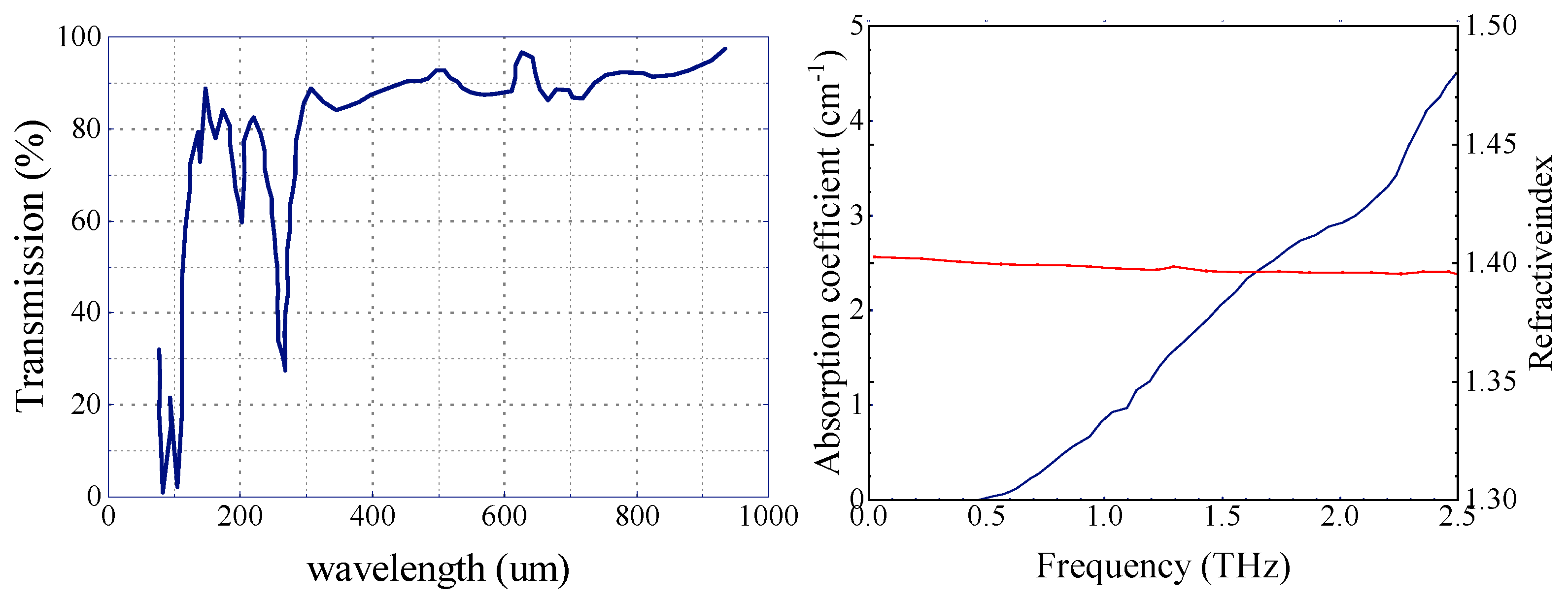
Before designing, it is essential to determine the material for lens processing. Polytetrafluoroethylene (PTFE) is commonly used as a lens material in the sub-terahertz and terahertz frequency bands[
38]. It is a white, hard and heavy plastic. Its density is around 2.2 g/cm3. PTFE melts at 327°C and retains its useful properties in a wide temperature range between -73°C and 204°C[
39,
40]. Refractive index is 1.4 in a wide wavelength range. PTFE has a low dielectric constant, about 1.96 at 520 GHz, which means its insertion loss is relatively low[
41].
Figure 3.
Transmission of PTFE film~0.1 mm thick and THz refractive index and absorption coefficient in PTFE.
Figure 3.
Transmission of PTFE film~0.1 mm thick and THz refractive index and absorption coefficient in PTFE.
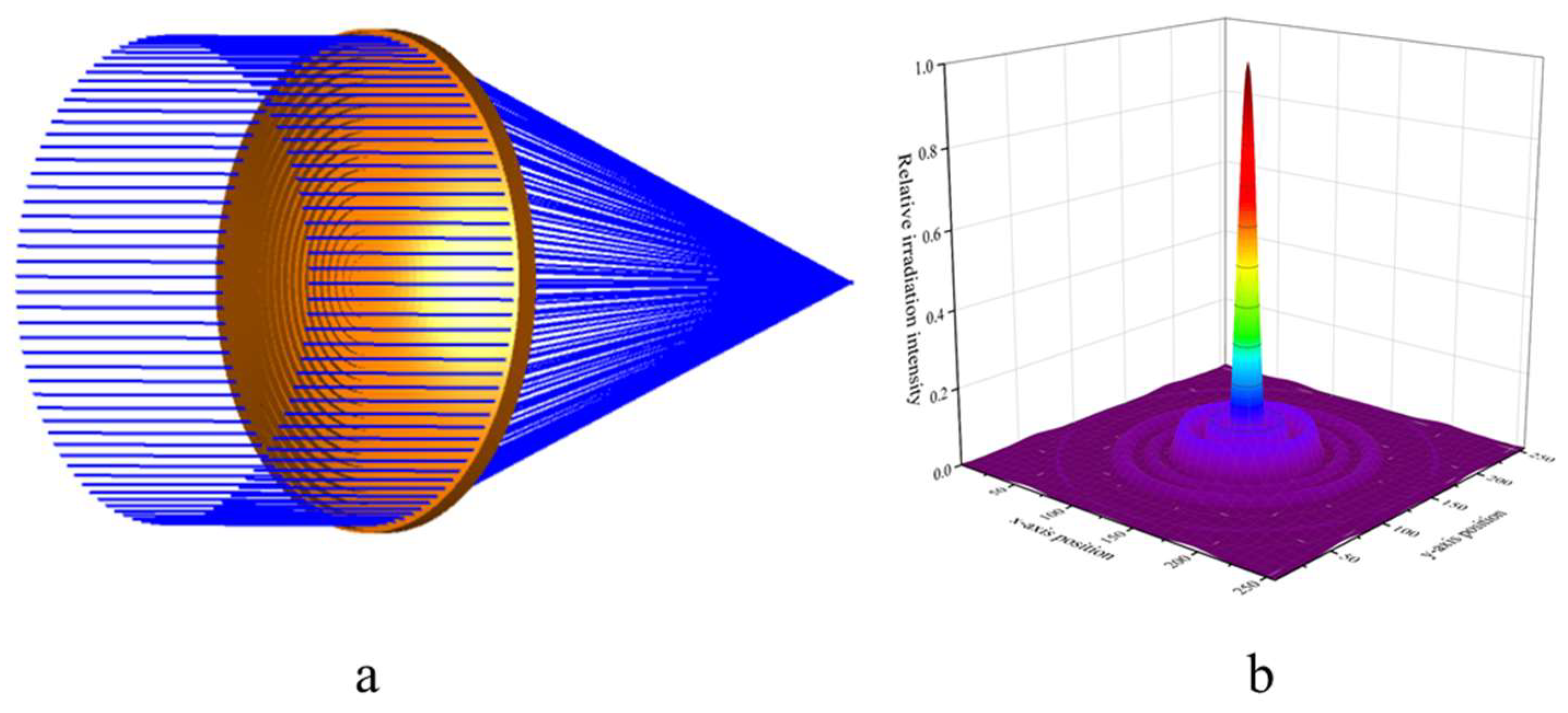
We designed a Fresnel lens with an effective aperture of 30 cm based on a frequency of 300 GHz. The parameters of the Fresnel lens were iteratively adjusted using the prism method. Afterward, the designed model was subjected to 3D modeling and ray tracing in optical software. The results are shown in
Figure 4. During the optimization process, we appropriately reduced the number of rings on the Fresnel lens, considering the limitations of practical manufacturing.
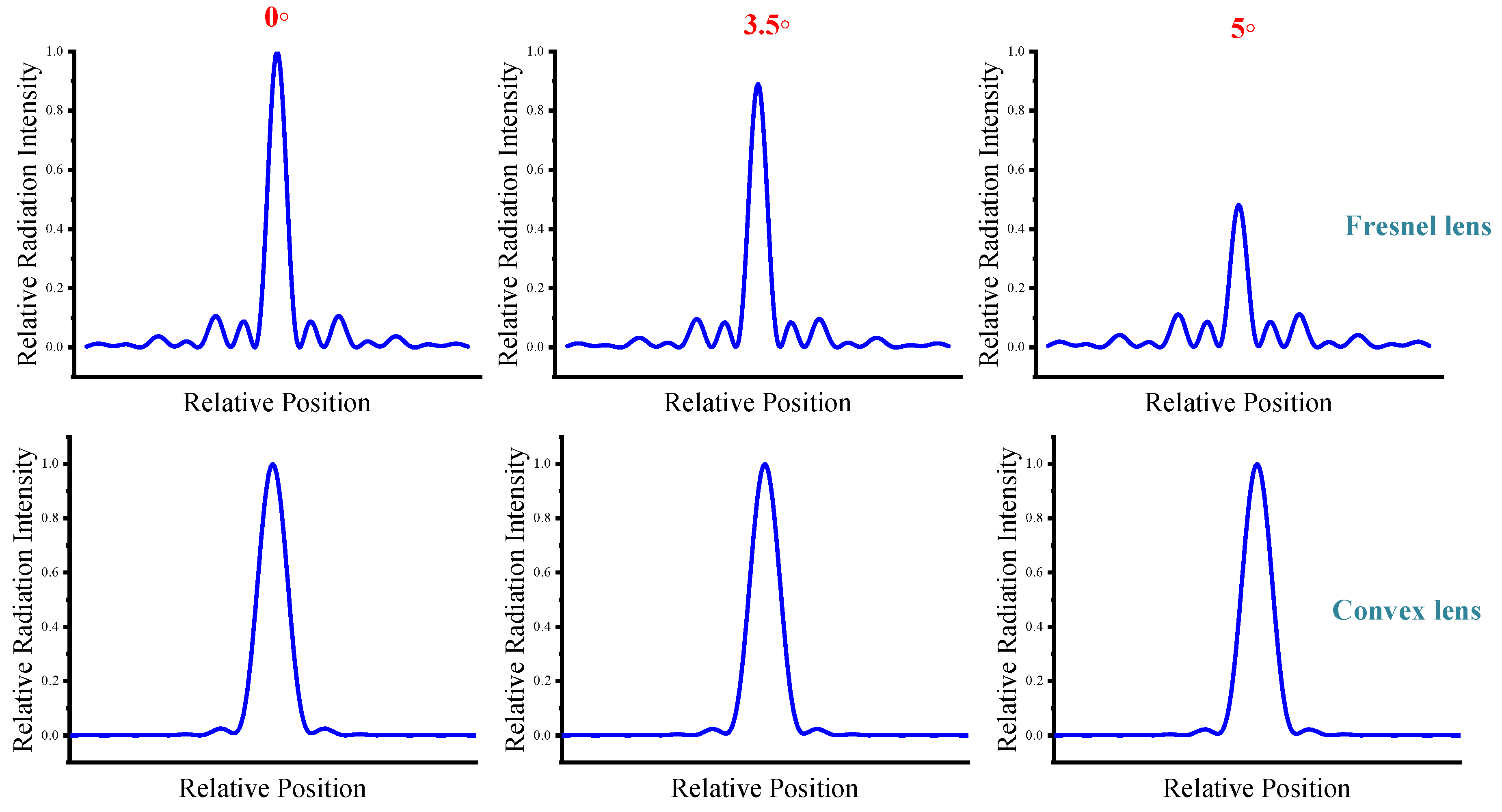
It is worth noting that compared to plano-convex lenses, Fresnel lenses are highly sensitive to changes in the incident angle. We now simulate the energy distribution on the focal plane for lens receiving angles of 0°, 3.5°, and 5° respectively. As shown in
Figure 5, as the incident angle of the Fresnel lens increases, the on-axis radiation drops dramatically. This situation is also caused by the sectional design of the Fresnel lens, which is a structural defect that can be mitigated by wave collimation. In comparison, changes in the incident angle have a much smaller impact on plano-convex lenses. Therefore, plane equidistant Fresnel lenses are extremely sensitive to changes in the incident light angle, which imposes higher requirements on terahertz antenna alignment technology.
2.5. Estimation of Lens Antenna Gain
A lens antenna is considered an aperture antenna, and its gain can be estimated using a formula based on the effective aperture:
is the effective area of the antenna and
is the signal wavelength. Taking into account the antenna efficiency
and the antenna diameter
(effective aperture), we obtain:
For traditional lens antennas, antenna efficiency refers to the ability of the antenna to effectively convert input power into radiated power. Antenna efficiency is typically influenced by several factors, such as material absorption losses, surface roughness, matching losses, reflection losses, environmental factors (temperature and humidity), edge diffraction, and the lens's focal length (F-number). In the case of Fresnel lenses, special attention must also be paid to structural losses and frequency dependence. Additionally, the sensitivity to incident angles may increase matching losses.
Given these complexities, accurately calculating the gain of a lens antenna can be challenging. Instead, we can use the Strehl ratio calculated by optical software as a simplified substitute for antenna efficiency in our estimation. The Strehl ratio is defined as the ratio of the peak intensity on the optical axis in the actual beam's far-field to that of an ideal beam with the same power and uniform phase. It is a measure of the quality of the optical energy distribution in an optical system.
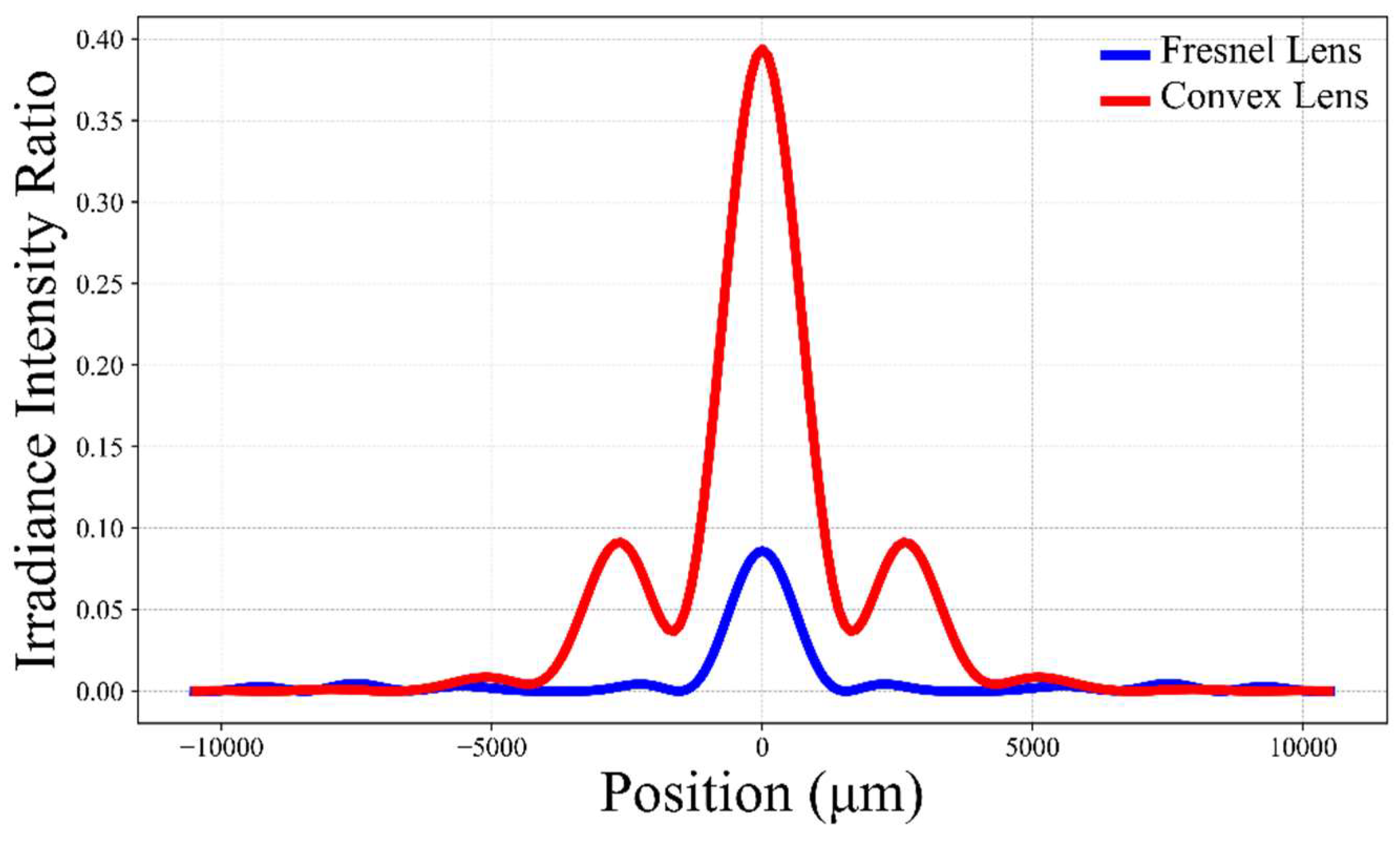
We performed optical simulations for both a plano-convex lens and a Fresnel lens with an effective diameter of 30 cm, resulting in the relative irradiance intensity curves on the focal plane for the two lenses, as shown in
Figure 6. Using the Strehl ratio as the peak value and with a working wavelength of 1 mm (300 GHz), the calculated gains for the plano-convex lens and the Fresnel lens are 55.44 dB and 48.83 dB, respectively, with a difference of approximately 6.61dB. It is important to note that the Strehl ratio is an indicator of image quality, and when there is significant aberration, the Strehl ratio can be very low. Therefore, the estimated gain using this method is likely lower than the actual gain.
3. Experimental Setup
We designed a Fresnel lens with an effective diameter of 30 cm based on the 300 GHz frequency band and fabricated it using polytetrafluoroethylene (PTFE). To validate the performance of the Fresnel lens, we set up a terahertz wireless transmission system.
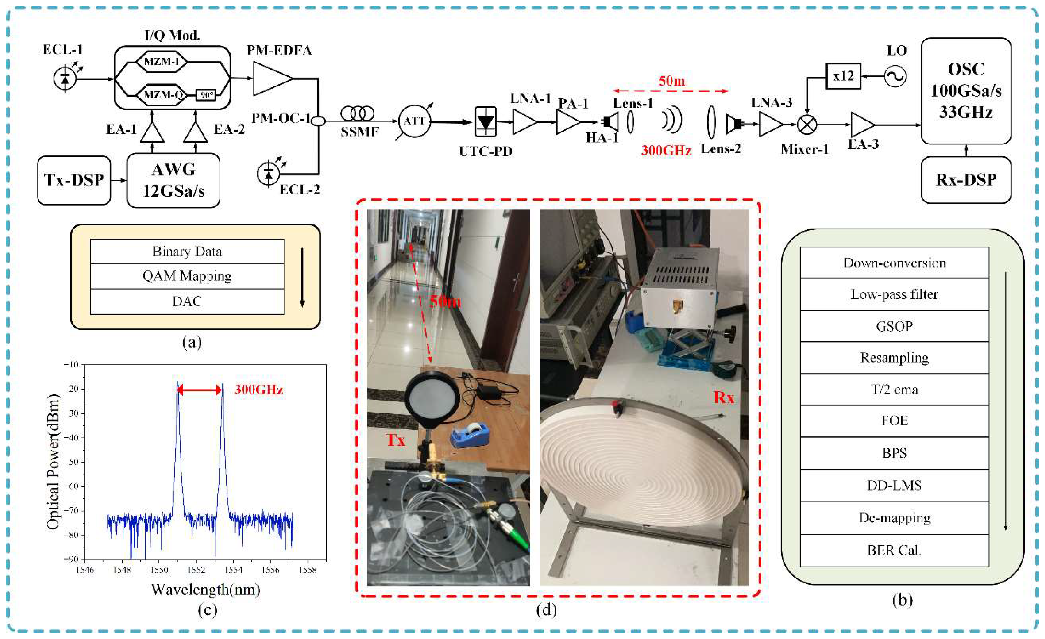
Figure 7 shows the experimental setup for photon-assisted 300 GHz terahertz signal transmission over a 50-meter wireless link. The baseband signal generation process is carried out offline in MATLAB at the transmitter. Initially, the bit sequence is mapped into QAM (Quadrature Amplitude Modulation) signals, followed by digital-to-analog conversion (DAC). This digital signal is then loaded into a 120GSa/s arbitrary waveform generator (AWG) to generate QAM signals at different baud rates. These signals are then amplified by two parallel electrical amplifiers (EAs) with 25 dB gain each. The setup incorporates two free-running external cavity lasers (ECLs), labeled as ECL-1 and ECL-2, each with a linewidth of 100 kHz. ECL-1 emits a continuous optical wave at 1550.00 nm, while ECL-2 operates at 1552.4 nm. The I/Q modulator, which has a 30 GHz 3dB bandwidth, is driven by an optical carrier emitted by ECL-1, completing the optical modulation process. The signal, amplified to post-modulation by a polarization-maintaining erbium-doped fiber amplifier (PM-EDFA), is then combined with another optical carrier emitted by ECL-2 using a polarization-maintaining optical coupler (PM-OC). The transmitted signal, after traversing 100 meters of SMF-28 (Single-Mode Fiber-28), is regulated in optical power using a variable optical attenuator (VOA) before entering the uni-traveling-carrier photodiode (UTC-PD). Inside the UTC-PD, 300 GHz THz signals are generated through optical heterodyne technology. Due to the rapid attenuation experienced by the THz band signal during free-space transmission, the signal requires amplification. This is achieved by employing a cascaded Low Noise Amplifier (LNA-1) and a Power Amplifier (PA-1) to support wireless transmission across a 50-meter distance. The amplified signal is then transmitted into free space through a transmitter horn antenna (HA-1) with a 25dBi gain. We placed a pair of lenses, Lens-1 and Lens-2, in front of the transmitter and receiver antennas. Lens-1 is a 10 cm diameter plano-convex lens, and Lens-2 is the 30 cm diameter Fresnel lens designed for this experiment. Due to the Fresnel lens's sensitivity to incident angles, precise alignment of Lens-1 and Lens-2 is crucial. Inadequate alignment can result in significant signal loss, negatively impacting the overall system performance. We used some auxiliary tools for correction. Our transmitter and receiver are set up in the corridors of the laboratory building at the Jiangwan campus of Fudan University, where the indoor temperature and humidity are well-controlled.
At the wireless receiver end, the signal initially undergoes amplification by LNA-2, providing a gain of 33dB. Subsequently, a local oscillator (LO) signal undergoes 12-fold amplification in the mixer. It is then mixed with the THz signal and downconverted to an intermediate frequency (IF) signal. After down-conversion, the IF signals are further amplified by EA-3 with a gain of 26dB. Finally, these signals are captured by a digital storage oscilloscope (OSC). The parameters of key devices in the experimental setup are shown in
Table 1.
Figure 7(d) shows photos of the transmitter and receiver setups.
The obtained IF signal, captured by the OSC, undergoes offline digital signal processing (DSP) in MATLAB. The offline DSP process at the receiver (Rx) involves multiple stages: down-conversion, low-pass filter, Gram-Schmidt Orthogonalization Procedure (GSOP), resampling, T/2 constant modulus algorithm (CMA) equalization, frequency offset estimation (FOE), blind phase search (BPS), and direct detection minimum mean square error (DD-LMS) equalization. Initially, the intermediate frequency signal is shifted to baseband through down-conversion. Next, the baseband signal passes through a low-pass filter to remove high-frequency noise, and the GSOP is applied to address IQ imbalance. Subsequently, CMA linear equalization and DD-LMS compensation address the inter-symbol interference caused by channel propagation characteristics. The FOE compensates for the frequency drift effect induced by laser frequency offset. The BPS improves the phase noise introduced by the linewidth of the laser. The distinct procedures pertaining to transmitter DSP (Tx-DSP) and receiver DSP (Rx-DSP) are illustrated in
Figure 7(a) and (b).
We use the Friis free space propagation model to calculate the power budget of a wireless link[
42,
43,
44]. Let d represent the distance between the transmitting antenna and the receiving antenna in free space. Assuming the transmitting antenna is an ideal omnidirectional antenna, the received signal power at the receiving point is:
In the formula,
represents the transmitted power. Considering the directional gain
of the transmitting antenna, the effective aperture
of the receiving antenna, and the atmospheric loss
:
Converting the units to dBm and using the logarithmic model:
The atmospheric loss in the terahertz band is approximately 10 dB/km. In a short-distance terahertz transmission system of 50 meters, the impact of atmospheric loss is minimal. The Free Space Path Loss (FSPL) is:
Table 2 outlines the power budget for each of the components used in our experimental system. When the input optical power of the UTC-PD is 14 dBm, the typical output power of UTC-PD at 300 GHz is roughly -8 dBm.
refers to the gain of the receiving antenna, including the lens and the horn feed (with a gain of 25dB). Considering the coupling efficiency between the lens and the feed, imperfections in lens manufacturing precision, and errors caused by multipath effects in the indoor corridor, these losses are estimated to be around 25dB. The calculated actual gain of the lens is approximately 45dB, which is close to the theoretical calculation.
4. Experimental Validation
The experimental results of
Figure 8 (a) show a significant increase in Bit Error Rate (BER) as the transmission rate increases. This indicates that at higher transmission rates, the signal quality deteriorates, likely due to reduced Signal-to-Noise Ratio (SNR) caused by increased bandwidth. At a transmission rate of 5GBaud, the QPSK signal’s BER remains within the Hard Decision Forward Error Correction (HD-FEC) threshold of 3.8×10⁻³. However, at 10GBaud, although the BER exceeds the HD-FEC threshold, it still remains below the Soft Decision Forward Error Correction (SD-FEC) threshold of 2.4×10⁻
2. At 5GBaud, the constellation points are well-defined, indicating good signal integrity.
The
Figure 8 (b) shows that BER significantly decreases as input optical power increases. This trend suggests that increasing input power effectively improves signal quality and reduces BER. At 14dBm input optical power, the signal's BER meets the HD-FEC thresholds. The above results verify the practical application of the Fresnel lens we designed in terahertz systems.
The
Figure 8 (c) illustrates the BER performance across different frequencies for 5GBaud QPSK with 14 dBm input optical power. Since the lens is designed for 300 GHz, its efficiency drops significantly at other frequencies. The further away from the design frequency band, the worse the system performance becomes. This validates the frequency selectivity of the Fresnel lens. This means that the Fresnel lens performs best near the design frequency (295 GHz to 305 GHz), while it focusses ability and signal quality decrease significantly when operating away from the design frequency. This frequency selectivity characteristic makes the Fresnel lens particularly suitable for high-precision applications in specific frequency bands, but its performance may be limited in wideband applications.
5. Conclusions
In terahertz communication systems, transceiver antennas typically use plano-convex dielectric lenses, but these become bulky as aperture size increases and focal length decreases. To address this, we designed a Fresnel lens optimized for the terahertz band, balancing large aperture and short focal length. Through theoretical analysis and simulation, we evaluated its performance. A 300 GHz wireless communication system was built to test the Fresnel lens's gain, and results show it effectively amplifies signals, with a gain close to that of a standard plano-convex lens. The theoretical gain of a 30 cm Fresnel lens is 48.83 dB, while the actual measured gain is approximately 45 dB. In practice, due to factors such as installation errors, alignment errors, manufacturing precision, and aging, the actual gain may vary.
Institutional Review Board Statement
Not applicable.
Informed Consent Statement
Not applicable.
Data Availability Statement
Not applicable.
Conflicts of Interest
The authors declare no conflict of interest.
References
- Farhad, A.; Pyun, J.-Y. Terahertz Meets AI: The State of the Art. Sensors 2023, 23. [Google Scholar] [CrossRef]
- Bauer, M.; Friederich, F. Terahertz and Millimeter Wave Sensing and Applications. Sensors 2022, 22. [Google Scholar] [CrossRef]
- Nagatsuma, T.; Horiguchi, S.; Minamikata, Y.; Yoshimizu, Y.; Hisatake, S.; Kuwano, S.; Yoshimoto, N.; Terada, J.; Takahashi, H. Terahertz Wireless Communications Based on Photonics Technologies. Optics express 2013, 21, 23736–23747. [Google Scholar] [CrossRef]
- Wang, M.; Wang, Y.; Li, W.; Ding, J.; Bian, C.; Wang, X.; Wang, C.; Li, C.; Zhong, Z.; Yu, J. Reflection Characteristics Measurements of Indoor Wireless Link in D-Band. Sensors 2022, 22, 6908. [Google Scholar] [CrossRef]
- Cai, Y.; Xiang, S.; Zhu, M.; Luo, W.; Lei, M.; Zhang, J.; Hua, B.; Zou, Y.; Fang, M.; Tian, L.; et al. Spectrally Efficient Multi-Service Fiber-Wireless Access in Low-Cost Direct-Detection THz System at 300 GHz. Optics Letters 2023, 48, 4554–4557. [Google Scholar] [CrossRef]
- Ding, J.; Wang, M.; Li, W.; Zhu, B.; Wang, F.; Wang, C.; Wang, Y.; Zhou, W.; Zhang, J.; Zhu, M.; et al. Wireless Transmission of a 200-m PS-64QAM THz-Wave Signal Using a Likelihood-Based Selection Radius-Directed Equalizer. Optics Letters 2022, 47, 3904–3907. [Google Scholar] [CrossRef]
- Li, W.; Yu, J.; Zhu, B.; Wang, F.; Ding, J.; Zhang, J.; Zhu, M.; Zhao, F.; Xie, T.; Wang, K.; et al. Photonic Terahertz Wireless Communication: Towards the Goal of High-Speed Kilometer-Level Transmission. Journal of Lightwave Technology 2023. [Google Scholar] [CrossRef]
- Li, W.; Yu, J.; Zhu, B.; Wang, F.; Tan, Y.; Wang, Y.; Zhu, M.; Zhang, J.; Zhou, W.; Zhao, F.; et al. Photonics-Aided THz-Wireless Transmission over 400 m at 335 GHz 2022.
- Li, X.; Yu, J.; Chang, G.-K. Photonics-Aided Millimeter-Wave Technologies for Extreme Mobile Broadband Communications in 5G. Journal of Lightwave Technology 2019, 38, 366–378. [Google Scholar] [CrossRef]
- Ding, J.; Yu, J.; Li, W.; Wang, K.; Zhou, W.; Zhang, J.; Zhu, M.; Xie, T.; Yu, J.; Zhao, F. High-Speed and Long-Distance Photonics-Aided Terahertz Wireless Communication. Journal of Lightwave Technology 2023, 41, 3417–3423. [Google Scholar] [CrossRef]
- Li, X.; Yu, J.; Wang, K.; Kong, M.; Zhou, W.; Zhu, Z.; Wang, C.; Zhao, M.; Chang, G.-K. 120 Gb/s Wireless Terahertz-Wave Signal Delivery by 375 GHz-500 GHz Multi-Carrier in a 2\times 2 MIMO System. Journal of Lightwave Technology 2018, 37, 606–611. [Google Scholar] [CrossRef]
- Yu, J.; Wang, Y.; Ding, J.; Zhang, J.; Li, W.; Wang, F.; Wang, C.; Wang, K.; Tan, Y.; Zhu, M.; et al. Broadband Photon-Assisted Terahertz Communication and Sensing. Journal of Lightwave Technology 2023, 41, 3332–3349. [Google Scholar] [CrossRef]
- Thornton, J.; Huang, K.-C. Modern Lens Antennas for Communications Engineering; John Wiley & Sons, 2013; Volume 39. [Google Scholar]
- Zeng, Y.; Zhang, R. Millimeter Wave MIMO with Lens Antenna Array: A New Path Division Multiplexing Paradigm. IEEE Transactions on Communications 2016, 64, 1557–1571. [Google Scholar] [CrossRef]
- Quevedo-Teruel, O.; Ebrahimpouri, M.; Ghasemifard, F. Lens Antennas for 5G Communications Systems. IEEE Communications Magazine 2018, 56, 36–41. [Google Scholar] [CrossRef]
- Nian, S.-C.; Chen, P.-W.; Huang, M.-S. Multilayer Injection Molding of High-Profile Convex Lens. Journal of Applied Polymer Science 2020, 137, 48600. [Google Scholar] [CrossRef]
- Chang, C.-Y. Development of a Rapid Manufacturing Process for Concave and Convex Lens Arrays. 2018.
- Wang, M.; Yu, J. 104-m Wireless Transmission of 4096-QAM for Mobile Backhaul Based on Delta-Sigma Modulation in 145 GHz 2023.
- Wang, M.; Yu, J.; Li, W.; Wei, Y.; Yang, X.; Shi, J.; Bian, C.; Zhou, W.; Wang, K. SNR Improved Digital-Analog Radio-over-Fiber Scheme for a Millimeter Wireless Fronthaul. Journal of Lightwave Technology 2023. [Google Scholar] [CrossRef]
- Wang, M.; Yu, J.; Zhao, X.; Li, W.; Wei, Y.; Yang, X.; Shi, J.; Bian, C.; Xie, T.; Zhao, F.; et al. SNR Improved Digital-Delta-Sigma-Modulation Radio-over-Fiber Scheme for D-Band 4.6-Km Photonics-Aided Wireless Fronthaul. Optics Letters 2023, 48, 3997–4000. [Google Scholar] [CrossRef]
- Wang, M.; Yu, J.; Zhao, X.; Bian, C.; Zhou, W.; Wang, K. K-Means Non-Uniform-Quantization Digital–Analog Radio-over-Fiber Scheme for THz-Band Photonics-Aided Wireless Fronthaul. Optics Letters 2024, 49, 2801–2804. [Google Scholar] [CrossRef]
- Wei, Y.; Yu, J.; Zhao, X.; Yang, X.; Wang, M.; Li, W.; Tian, P.; Han, Y.; Zhang, Q.; Tan, J.; et al. Demonstration of a Photonics-Aided 4,600-m Wireless Transmission System in the Sub-THz Band. Journal of Lightwave Technology 2024. [Google Scholar] [CrossRef]
- Kumar, V.; Shrivastava, R.; Untawale, S. Fresnel Lens: A Promising Alternative of Reflectors in Concentrated Solar Power. Renewable and Sustainable Energy Reviews 2015, 44, 376–390. [Google Scholar] [CrossRef]
- Tan, N.Y.J.; Zhang, X.; Neo, D.W.K.; Huang, R.; Liu, K.; Kumar, A.S. A Review of Recent Advances in Fabrication of Optical Fresnel Lenses. Journal of Manufacturing Processes 2021, 71, 113–133. [Google Scholar] [CrossRef]
- Xie, W.; Dai, Y.; Wang, R.; Sumathy, K. Concentrated Solar Energy Applications Using Fresnel Lenses: A Review. Renewable and Sustainable Energy Reviews 2011, 15, 2588–2606. [Google Scholar] [CrossRef]
- Tripanagnostopoulos, Y.; Siabekou, C.; Tonui, J. The Fresnel Lens Concept for Solar Control of Buildings. Solar Energy 2007, 81, 661–675. [Google Scholar] [CrossRef]
- Sierra, C.; Vazquez, A.J. High Solar Energy Concentration with a Fresnel Lens. Journal of materials science 2005, 40, 1339–1343. [Google Scholar] [CrossRef]
- Miller, D.C.; Kurtz, S.R. Durability of Fresnel Lenses: A Review Specific to the Concentrating Photovoltaic Application. Solar Energy Materials and Solar Cells 2011, 95, 2037–2068. [Google Scholar] [CrossRef]
- Egger, J.R. Use of Fresnel Lenses in Optical Systems: Some Advantages and Limitations. In Proceedings of the Optical Systems in Engineering I.; SPIE, 1979; Vol. 193; pp. 63–69. [Google Scholar]
- Rauch, J. Hyperbolic Partial Differential Equations and Geometric Optics; American Mathematical Soc., 2012; Vol. 133;
- Kravtsov, Y.A.; Orlov, Y.I. Limits of Applicability of the Method of Geometric Optics and Related Problems. Soviet Physics Uspekhi 1980, 23, 750. [Google Scholar] [CrossRef]
- Wyrowski, F.; Zhong, H.; Zhang, S.; Hellmann, C. Approximate Solution of Maxwell’s Equations by Geometrical Optics. In Proceedings of the Optical Systems Design 2015: Computational Optics; SPIE, 2015; Vol. 9630; pp. 20–38. [Google Scholar]
- Leutz, R.; Suzuki, A.; Akisawa, A.; Kashiwagi, T. Shaped Nonimaging Fresnel Lenses. Journal of Optics A: Pure and Applied Optics 2000, 2, 112. [Google Scholar] [CrossRef]
- Akisawa, A.; Hiramatsu, M.; Ozaki, K. Design of Dome-Shaped Non-Imaging Fresnel Lenses Taking Chromatic Aberration into Account. Solar Energy 2012, 86, 877–885. [Google Scholar] [CrossRef]
- Leutz, R.; Suzuki, A.; Leutz, R.; Suzuki, A. Nonimaging Fresnel Lens Design. Nonimaging Fresnel Lenses: Design and Performance of Solar Concentrators 2001, 77–99.
- Leutz, R.; Suzuki, A. Nonimaging Fresnel Lenses: Design and Performance of Solar Concentrators; Springer, 2012; Vol. 83;
- Yeh, N.; Yeh, P. Analysis of Point-Focused, Non-Imaging Fresnel Lenses’ Concentration Profile and Manufacture Parameters. Renewable Energy 2016, 85, 514–523. [Google Scholar] [CrossRef]
- Biswas, S.; Vijayan, K. Friction and Wear of PTFE—a Review. Wear 1992, 158, 193–211. [Google Scholar] [CrossRef]
- Dhanumalayan, E.; Joshi, G.M. Performance Properties and Applications of Polytetrafluoroethylene (PTFE)—a Review. Advanced Composites and Hybrid Materials 2018, 1, 247–268. [Google Scholar] [CrossRef]
- Price, D.M.; Jarratt, M. Thermal Conductivity of PTFE and PTFE Composites. Thermochimica acta 2002, 392, 231–236. [Google Scholar] [CrossRef]
- Naftaly, M.; Miles, R.; Greenslade, P. THz Transmission in Polymer Materials—a Data Library. In Proceedings of the 2007 Joint 32nd International Conference on Infrared and Millimeter Waves and the 15th International Conference on Terahertz Electronics; IEEE, 2007; pp. 819–820. [Google Scholar]
- Levis, C.A. Friis Free-Space Transmission Formula. Encyclopedia of RF and Microwave Engineering 2005. [Google Scholar]
- Shaw, J.A. Radiometry and the Friis Transmission Equation. American journal of physics 2013, 81, 33–37. [Google Scholar] [CrossRef]
- Promwong, S.; Panthap, P. Experimental Evaluation of Complex Form Friis’ Transmission Formula with Indoor/Outdoor for Ultra Wideband Inpulse Radio. In Proceedings of the 2008 International Conference on Computer and Communication Engineering; IEEE, 2008; pp. 1037–1041. [Google Scholar]
|
Disclaimer/Publisher’s Note: The statements, opinions and data contained in all publications are solely those of the individual author(s) and contributor(s) and not of MDPI and/or the editor(s). MDPI and/or the editor(s) disclaim responsibility for any injury to people or property resulting from any ideas, methods, instructions or products referred to in the content. |
© 2024 by the authors. Licensee MDPI, Basel, Switzerland. This article is an open access article distributed under the terms and conditions of the Creative Commons Attribution (CC BY) license (http://creativecommons.org/licenses/by/4.0/).
