
Submitted:
16 September 2024
Posted:
18 September 2024
You are already at the latest version
Abstract
The recent commercial availability of stacked dielectric elastomer actuators (SDEAs) has unlocked new opportunities for their application as "artificial skeletal muscles" in rehabilitation robots and powered exoskeletons. Composed of multiple layers of thin, elastic capacitors, these actuators present a lightweight, soft, and acoustically noiseless alternative to traditional DC motor actuators commonly used in rehabilitation robotics, thereby enhancing the natural feel of such systems. Building on our previous research, this study aimed to evaluate the most recent version of commercial SDEAs to assess their potential for mechanizing rehabilitation robots. We quantified the stress and strain behavior and stiffness of these actuators in both single and 1x3 configurations (with three SDEAs connected in series). The actuators demonstrated the capability to generate up to 25 N of force, 103 KPa, a value closely resembling human biceps, with a longitudinal strain measured at about 11%. The significant increase in force generation from 10 N, in the previous version, to 25 N and displacement from 3.3% to 11% substantially enhances the applicability of this actuator rehabilitation robotics. SDEAs' high force generation capability, combined with their strain and stress characteristics comparable to that of human biological muscles make them ideal alternative actuators for biomimetic robots and applications where actuators must operate in the vicinity of the human body.
Keywords:
Actuators
; Muscles
; Rehabilitation robotics
; Soft robotics
; SDEA
; Force
1. Introduction
Enhancing the effectiveness and acceptance of rehabilitation robots necessitates the development of actuator technology that feels more natural. Incorporating softness, defined as possessing Young's modulus similar to that of biological tissues, can enhance the device's safety, flexibility, and tactile sensation (1). When softness is combined with noiseless and linear functioning, it creates a muscle-like actuator ideal for rehabilitation applications, particularly in exoskeletons where the actuator operates near human limbs. The linear movement of these alternative actuators allows them to align with the skeletal system, mimicking skeletal muscle, thus minimizing the bulkiness of the exoskeletal structure. Additionally, linear movement, when paired with softness, adapts to complex shapes and allows for multiple movement possibilities with a single actuator (2). For exoskeletons, it is advantageous for the actuator to generate forces and movements on par with those of mammalian skeletal muscle. Such an actuator, characterized by its softness, quiet operation, linear motion, and ability to match the force and displacement of skeletal muscle, is termed an artificial skeletal muscle.
The potential candidates for artificial skeletal muscles are generally categorized into two types: thermally driven and electroactive polymers. Thermally driven polymer actuators tend to be more powerful, particularly in terms of their strain capacity, compared to electroactive actuators. For instance, a 2 g ethanol-based phase-change actuator developed by Miriyev's team was capable of exerting up to 120 N of force and achieving 140% strain (3). In contrast, electroactive polymers exhibit slower actuation speeds (about 2.5 %/s strain-rate) and significantly lower efficiencies (0.2%). These characteristics present considerable drawbacks for exoskeleton applications, which require quick and repetitive longitudinal movements (contractions).
Soft electroactive polymer actuators like dielectric elastomer actuators (DEAs) provide a fast, efficient, and quiet alternative to the conventional DC motor actuators found in standard rehabilitation robotic systems. DEAs exhibit remarkable muscle-like properties, positioning them as highly promising and frequently studied soft actuators. Notably, mammalian skeletal muscle functions similarly to an electroactive polymer. Dielectric elastomer actuators are essentially composed of a compliant capacitor featuring an elastic dielectric material encased between two mechanically compliant electrodes (Figure 1A). When a DC voltage is applied across these electrodes, the resulting Maxwell pressure, electrostatic force-induced pressure between two oppositely charged plates, compresses the dielectric in the thickness direction. Equation (1) demonstrates the parabolic relationship between Maxwell pressure and voltage, where ε and represent the permittivity of the polymer and void respectively, V is the voltage applied across the electrodes, and d is the thickness.
Dielectric elastomer actuators (DEAs) possess several distinct characteristics, including high power-to-mass ratios that can exceed those of human skeletal muscles, rapid responsiveness, length self-sensing, and the ability to recuperate energy (4) (5). These actuators are notably efficient. When the capacitor is fully charged—meaning the DEA is completely contracted—the primary source of energy consumption is minimal dielectric leakage currents, typically in the microampere range (6). However, the requirement for high driving voltages (over 1 KV) can be problematic, as it not only restricts the selection of compatible electrical components but also raises significant safety concerns. Despite these high voltages, the low power requirements of DEAs (usually a few watts, due to their low operational currents) generally keep them within safe operational limits, particularly if adequate insulation measures are in place. Moreover, under a constant DC voltage, the rate at which a capacitor charges, and thus the contraction speed of the DEA, is governed by the applied electrical current, which can be adjusted to safe levels depending on the required actuation speed. Equation (2) details the relationship between charge Q and instantaneous current i. Additionally, the discharge rate of the DEA is a critical factor in safety assessments. Zhang et al. conducted simulations of their electrical system, demonstrating the safety of their DEA-based glove-like force feedback device in compliance with IEC TS 60479-2 standards (7) (8) .
DEAs) have shown significant potential as artificial skeletal muscles in orthotic and prosthetic applications. Carpi et al. pioneered the use of multilayer DEAs to mechanize a hand orthosis, demonstrating their practical utility in this domain (9). Another promising application of DEAs in rehabilitation is in the design of ankle-foot orthoses (AFOs) aimed at assisting individuals with walking disabilities. For instance, we have developed a DEA-based ankle-foot orthosis (DE-AFO) specifically tailored for children with cerebral palsy (10). Additionally, Allen et al. have designed an innovative DE-powered AFO, achieving an impressive 49% dorsiflexion during use (11).
DEAs are primarily available in two configurations: 1) freestanding DEAs, and 2) DEAs integrated with rigid frames. Rigid frames can be less suitable where flexibility and softness are required, often resulting in heavier and more cumbersome designs compared to their freestanding counterparts.
In applications for artificial skeletal muscles, freestanding configurations are particularly favored for their ability to impart a more natural feel to the design. Various freestanding configurations have been developed, including tubular (12), helical (13), folded (14) ,stacked (15) and rolled DEAs (16) (Table 1). DEAs have been constructed into cylindrical rolls, achieving strain, shape, and performance characteristics akin to natural skeletal muscles. Kunze, Julian, et al. developed compact, high-energy-density rolled DEAs for soft robotics and artificial muscles. Made from thin silicone films with flexible electrodes, these actuators show a blocking force change of 0.18 N and a 2.5% stroke at 2 N. The design is smaller than conventional DEAs, enabling compact soft robotic systems. Future work will optimize the design, eliminate the hollow core, and develop models to enhance performance. One rolled actuator was designed to resemble the shape of a biceps muscle and was implemented to function within a life-size skeletal arm model (16).
Among the free-standing configurations, the stacked DEAs developed by Kovacs et al. (15) stand out as highly powerful and versatile, bearing the closest resemblance to human skeletal muscle among the linear DEA configurations. Kovacs et al. innovatively layered multiple thin, enhanced DEAs to craft this advanced actuator. In this setup, each layer functions analogously to a sarcomere within a skeletal muscle's myofibril. This assembly of tensile actuators is capable of generating 32N of isometric force and 15% strain while managing a 1.1Kg tensile (14). These features have enabled these stacked DEAs to be the first and only commercially available model produced by a company named CTsystems (17), which we call CT-SDEAs in this study.
Previously, we assessed the mechanical properties of the CT-SDEA (model CT25.0-15-15-71, Compliant Transducer Systems, Dubendorf, Switzerland) and compared them to the reported values provided by CTsystems, as shown in Table 2. In this study, we benchmarked the latest version of this design, now manufactured by Dätwyler Schweiz AG (Schattdorf, Switzerland), to be incorporated as motor units in powered exoskeletons, including our latest ankle exoskeleton, DE-AFO—a comfortable ankle-foot orthosis (AFO) powered by SDEA-based artificial muscles (10). The dimensions of the evaluated actuator in this study are 15x15x50 mm, slightly different from the CT-SDEA's 30x17x17 mm. We refer to these actuators as SDEA-1550.
We measured the axial stiffness of SDEA-1550 and evaluated its stress and strain capabilities under three conditions: free-standing, isometric (constant length), and isotonic (constant tensile load). Additionally, we configured an artificial muscle by connecting three of these actuators in series (1x3 configuration) and tested it under the same conditions. To further assess the reliability of these actuators in producing force and displacement, we conducted a comparative analysis of 10 actuators.
2. Methods
2.1. Testing Procedure
To evaluate the performance of SDEA, tests were conducted under three conditions: free-standing, isometric, and isotonic contraction conditions. The actuators were activated using different driving voltages, from 0 to 1200 V, in 100 V increments.
2.2. Strain-Stress Testing Setup
A comprehensive test rig was designed and implemented to evaluate the performance of the SDEAs under all three aforementioned conditions, isometric, isotonic and free-standing contractions. The main components of this test rig include the aluminum mainframe, National Instrument’s (NI’s) data acquisition (DAQ) boards, laser displacement sensor, load cell, and precision translation stages.
A laser displacement sensor, model ILD 142025 (Micro-Epsilon, Ortenburg, Germany), was used to measure the longitudinal contraction displacement of the actuators (Figure 2). This sensor offers a precision of 1 μm, guaranteeing highly accurate displacement measurements. To measure both active and passive forces exerted by the SDEA-1550s, a load cell model LSB302 (FUTEK Advanced Sensor Technology, Inc. in Irvine, CA, USA), capable of handling up to 25 lb from (figure), was utilized. This load cell provides precise force measurements.
The setup also included three precision translational stages with 10 μm graduation and a 102 N axial load capacity, which allowed for fine-tuning the position of the load cell to ensure accurate alignment and load application (Figure 2). To provide the necessary driving voltage to the CT-SDEAs, we employed a high voltage (HV) fast amplifier (HA51U-1.6P10-3, hivolt.de, Hamburg, Germany) with a slew rate of 80 V/μs. Additionally, a 10 MΩ discharge resistor, recommended by CTsystems, was used for the hysteresis tests. This resistor choice ensured an appropriate discharge rate, further contributing to the accuracy and reliability of the hysteresis measurements. By incorporating the faster HV amplifier and the recommended discharge resistor, we were able to achieve more precise and consistent results in our force and displacement hysteresis tests, thereby improving the overall performance and reliability of the SDEAs.
Load cell data were collected via a H-Bridge Input Module (NI 9237, National Instruments in Austin, TX, USA) connected to a NI’s compact RIO (cRIO-9045), and HV amplifier was controlled via an NI DAQ Data Acquisition board (NI USB-6343, National Instruments in Austin, TX, USA). The displacement data of the laser sensor was collected via Micro-Epsilon’s homegrown software (sensorTOOL 1.12.0.1370).
NI MAX (version 2024 Q2) was employed to generate control voltages ranging from 0.625 to 7.5 V, which were subsequently amplified to 100 to 1200 V by the HV amplifier (1:160 ratio). Additionally, NI MAX was used to acquire force data from the load cell.
By integrating these high-precision sensors and advanced data acquisition systems, the test rig allowed for a comprehensive evaluation of the SDEAs' behavior under different loading scenarios, providing valuable insights into their capabilities and performance.
2.3. Isometric Condition
The experiments were conducted in three steps: 1) securing the SDEA between the load cell and the main frame, 2) precisely adjusting the SDEAs, and 3) applying the driving voltages and recording the load cell data. Initially, individual SDEAs were tested (a set of 10 actuators), followed by the testing of the artificial muscle in a 1x3 configuration.
Three precision translation stages—two at the base for adjusting the X and Y directions and one at the top for adjusting the actuator along the Z axis—provide the flexibility needed to precisely position the SDEAs under test (Figure 3). Laser beams were employed as guides for vertical alignment. Before activation, the Z-axis precision stage was carefully adjusted to virtually zero the load, ensuring the actuator was neither under tension nor compression. Then, the generated force under each activation voltage was recorded.
Using the data collected, maximum stress was calculated by dividing the averaged maximum force (reported as mean and one standard deviation) of the ten SDEA-1550s by the area of the SDEA’s end-plate (225 mm²).
2.4. Isotonic Condition
In the isotonic condition, as shown in Figure 4, the SDEAs were tested while suspended from the Z stage using a 3D printed bracket, with a series of tensile loads consisting of seven loads (100 to 700 gr in 100 gr increments) attached to the actuators. The contraction of the SDEA (Figure 4a) and the 1x3 configuration (Figure 4b) under these loaded conditions was measured by applying the activation voltages (from 100 V to 1200 V). Laser displacement sensor was beaming at the extended endplate of the lowest SDEA.
Using the data collected from the isotonic condition, the maximum longitudinal Strain was calculated by dividing the averaged maximum longitudinal contraction (reported as mean and standard deviation) of the SDEAs by their normal length of 50 mm.
2.5. Free-Standing Condition
In the free-standing condition, as shown in Figure 5, we fixed the actuator vertically to the base of the test rig’s mainframe. This setup ensured that the actuator remained stable throughout the testing process. The displacement generated by each driving voltage was then precisely measured using the laser displacement sensor. This sensor was mounted directly on top of the SDEAs. Single SDEA (Figure 5a) and 1x3 configurations (Figure 5b) were evaluated under this condition.
Between actuator compassion: a set of 10 SDEA-1550 went through all three conditions (Isometric, Isotonic, and free-standing) to compare the reliability of the actuators in producing force and displacement.
2.5. Stiffness
We evaluated single DEA's stiffness using a Shimadzu Universal Electromechanical Test Frame. The test was conducted under two orientations: vertical and horizontal, as shown in Figure 6. The objective was to determine the stiffness of the actuator when subjected to a constant displacement of 1 mm while applying different voltages.
The procedure involved placing the actuator on the test frame and applying a loads vertically and horizontally. The stiffness k was calculated using the following equation:
where F is the force applied by the Shimadzu Universal Electromechanical Test Frame, and d is the constant displacement of 1 mm.
This testing approach allowed us to assess the actuator's stiffness characteristics under varying conditions, providing valuable insights into its mechanical properties.
The force and displacement data for both single actuators and the assembled artificial muscle are presented in graphical form. For the comparison between actuators, we report the range, mean, and standard deviation (mean ± SD) of force and displacement, as well as the maximum and mean values of stress and strain. Note that the 1200 V was the recommended voltage for the old version, and the 800 V is the recommended voltage for the latest model; therefore, we focused on these two values more closely throughout the Results section.
3. Results
3.1. Isometric Condition
In the first experiment, conducted under isometric conditions, we tested a set of 10 randomly selected actuators. The results, shown in Figure 7, indicate that at the recommended voltage of 800 V, the measured force ranged from 9.37 N to 12.21 N, with an average of 10.92 ± 0.73 N. Based on the actuator's surface area of 225 mm², the minimum and maximum stresses were calculated as 41.64 KPa and 54.27 KPa, respectively.
By increasing the voltage to 1200 V, recommended for the previous version (CT-SDEA), a significant rise in force was observed, with forces ranging from 23.15 N to 28.75 N and a mean of 25.84 ± 1.50 N. The minimum and max stresses were calculated at 102.88 and 127.78 kPa, respectively.
3.2. Isotonic Condition
Figure 8 presents the displacements of the actuator under constant loads and different voltage levels for one actuator. The data indicates that the maximum displacement occurred with the minimum load of 100 g, as the actuator was able to compress more easily under lighter load conditions. As shown in the figure, the maximum shortening (displacement) at 1200 V occurs with a 100 g load that is -5.79 mm, while the minimum shortening is observed with a 700 g load that is -3.77 mm. For the recommended voltage (800 V), the maximum and minimum shortening at 100 g and 700 loads were -2.19 mm and -0.39 mm, respectively.
We compared the shortening of ten actuators under varying voltage levels while subjected to a constant 200 g load. As shown in Figure 9, at 1200 V, the range of shortening displacement is from -6.09 mm to -4.17 mm, with a mean value of -5.30 ±0.65 mm. The maximum strain observed at 1200 V is 12%. The mean of shorting at 800 v was -1.98 ± 0.14 mm with the maximum strain of 4.4%.
The result of the artificial muscle shortening under isotonic conditions is illustrated in Figure 10, as expected, the graph shows that the maximum displacement occurs at 1200 V, ranging from -17.92 mm to -14.04 mm for 100 g and 700 g loads, respectively, with a mean displacement of -16.43 ±1.48 mm.
3.3. Free-Standing Condition
As Figure 11 shows, at 1200 V, under free-standing conditions, the displacements ranged from -6.15 mm to -4.4 mm, with a mean displacement of -5.45 ±0.47 mm. The mean shortening at 800 V (the recommended voltage) was -2.25 ±0.24 mm. As the voltage increases, a significant difference of 1.75 mm is observed between actuators’ shortening at 1200 V.
Following the experiments conducted on ten individual actuators, we further tested 1x3 artificial muscle. The objective was to assess the combined displacement behavior of this configuration under varying voltage levels.
The results of these tests are presented in Figure 12, which illustrates the displacement of the series-connected actuators across a range of voltages from 0 to 1200 V. As depicted in the graph, the displacement increases with the applied voltage, reaching a maximum value of -16.44 mm at 1200 V, while the shortening at 800 V was -6.9 mm.
3.4. Stiffness
In the stiffness experiments, we tested the stiffness of an actuator along the X (horizontal) and Y (Vertical) directions under different voltages, ranging from 800 V to 1200 V. The results are presented in Figure 13. As shown in the graph, the actuator exhibit greater stiffness in the Y direction, with a maximum stiffness of 1.99 MPa at 1200 V. The stiffness in the X direction ranged from 0.034 MPa at 800 V to 0.086 MPa at 1200 V.
4. Discussion
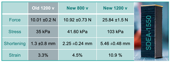
In this study, we benchmarked the latest version of the commercially available SDEA-1550, revealing substantial improvements over the previous CT-SDEA model we evaluated in our earlier research (18). The SDEA-1550 demonstrated a threefold enhancement in strain and stress, increasing from 3.3% to 10.9% strain and from 35 kPa to 103 kPa stress under the recommended driving voltage of the CT-SDEA. Notably, the recommended voltage for the SDEA-1550 has been reduced by approximately 30%, down to 800 V, which is a significant advantage in terms of compatibility with electronics and reduced power consumption. At 800 V, the SDEA-1550 exhibited 4.5% strain and 41.6 KPa stress. It is important to note that the pressure between the electrodes of each layer of the SDEA (each compliant capacitor stacked in parallel) is proportional to the square of the applied voltage (as described in Equation (1)). This relationship explains the substantial increase in both stress and strain when the voltage is increased from 800 V to 1200 V, as reflected in the logarithmic shape of the resulting graphs.
The mechanical properties of the SDEAs are approaching those of biological skeletal muscle, as highlighted in our previous work and in (19). Typical strain and stress values reported for human biceps muscle are around 20% and 100 KPa, respectively. Although the 11% strain measured for the SDEA-1550 is lower (slightly more than half) than that of the biceps, it represents a significant improvement—more than three times the value of previous iterations. Moreover, the stress generated by the SDEA-1550, 103 KPa, now closely matches that of the biceps, which is a remarkable achievement in the development of biomimetic actuators.
In the future, we aim to focus on controlling the force and displacement generation of these actuators and integrating them into exoskeleton designs for both upper (20) and lower limbs, such as DE-AFO (10). This could significantly benefit various populations with neuromotor pathologies, including individuals with cerebral palsy (21), stroke (22), and multiple sclerosis (MS) (23). Additionally, we will explore actively controlling the stiffness of the SDEAs, which could enhance the comfort and support provided by exoskeletons, particularly around bony structures. Leveraging from varying stiffness and length self-sensing capabilities of SDEAs , we see the potential for these actuators to be incorporated into hand exoskeletons and grippers with haptic control (24), which is another avenue we plan to investigate.
5. Conclusions
SDEAs are emerging as strong candidates for constructing artificial skeletal muscles, particularly in the context of biomimetic rehabilitation robots where the natural feel is a crucial component of user compliance. In this study, we evaluated the latest commercially available SDEAs produced by Dätwyler Schweiz AG and compared them to their previous versions produced by CTsystems. Our findings reveal that the new SDEAs exhibit substantially improved strain, and stress increased by more than 300%. The stress value now closely resembles the typical vlue reported for biceps of human. Combined with their muscle-like characteristics—such as longitudinal contraction, softness, and noiseless operation—these enhancements further establish SDEAs as increasingly comparable to biological human muscles. This progress underscores their potential as soft motor units in artificial skeletal muscles, reinforcing their suitability for next-generation rehabilitation robotics.
Author Contributions
Conceptualization, A.B. and S.C.K.L.; methodology, A.B. and V.M.; software, M.T. and V.M.; validation, A.B. and V.M.; formal analysis, V.M. and S.M.G; investigation, A.B. and V.M.; resources, A.B.; data curation, M.T., V.M and S.M.G; writing—original draft preparation, V.M.; writing—review and editing, A.B., V.M. and S.C.K.L; visualization, V.M. and M.T.; supervision, A.B.; project administration, A.B. and S.C.K.L; funding acquisition, A.B. All authors have read and agreed to the published version of the manuscript.
Funding
This research was funded by Shriners Hospitals for Children—Philadelphia, Grant No. 71011-PHI; the National Science Foundation I-Corps, Grant No. 1906128; the University Science Center’s QED award, Project No. 1803; and the National Institute of Health DE-CTR ACCEL, Grant No. U54-GM104941
Acknowledgments
This research was supported by the National Institutes of Health (NIH) under Grants P20GM109090 and P20GM152301. We would like to express our sincere gratitude to NIH for their generous funding, which made this project possible. The resources and support provided through these grants have been instrumental in advancing our research on rehabilitation robotics and artificial skeletal muscles.
Conflicts of Interest
The corresponding authors are founders of Elasthetics LLC, which is established to potentially commercialize DE-AFO in the future.
References
- Rus D, Tolley MT. Design, fabrication and control of soft robots. Nature. 2015 May 28;521(7553):467–75. [CrossRef]
- Verl A, Albu-Schäffer A, Brock O, Raatz A, editors. Soft Robotics: Transferring Theory to Application [Internet]. Berlin, Heidelberg: Springer Berlin Heidelberg; 2015 [cited 2024 Aug 25]. Available from: https://link.springer.com/10.1007/978-3-662-44506-8.
- Miriyev A, Stack K, Lipson H. Soft material for soft actuators. Nat Commun. 2017 Sep 19;8(1):596. [CrossRef]
- Yoo IS, Reitelshöfer S, Landgraf M, Franke J. Artificial Muscles, Made of Dielectric Elastomer Actuators - A Promising Solution for Inherently Compliant Future Robots. In: Verl A, Albu-Schäffer A, Brock O, Raatz A, editors. Soft Robotics [Internet]. Berlin, Heidelberg: Springer Berlin Heidelberg; 2015 [cited 2024 Aug 25]. p. 33–41. Available from: https://link.springer.com/10.1007/978-3-662-44506-8_4. [CrossRef]
- Carpi F, De Rossi D, Kornbluh R, Pelrine RE, Sommer-Larsen P, editors. Dielectric Elastomers as Electromechanical Transducers. Elsevier Science; 2011.
- Hoffstadt T, Griese M, Maas J. Online identification algorithms for integrated dielectric electroactive polymer sensors and self-sensing concepts. Smart Mater Struct. 2014 Oct 1;23(10):104007. [CrossRef]
- Rui Zhang, Kunz A, Lochmatter P, Kovacs G. Dielectric Elastomer Spring Roll Actuators for a Portable Force Feedback Device. In: 2006 14th Symposium on Haptic Interfaces for Virtual Environment and Teleoperator Systems [Internet]. Alexandria, VA, USA: IEEE; 2006 [cited 2024 Aug 25]. p. 347–53. Available from: http://ieeexplore.ieee.org/document/1627137/. [CrossRef]
- T. IEC, “60479-2: 2007 Effects of current on human beings and livestock”, Part. [Internet]. Available from: https://scholar.google.com/scholar?as_q=60479-2%3A+2007+Effects+of+current+on+human+beings+and+livestock&as_occt=title&hl=en&as_sdt=0%2C31.
- Carpi F, Frediani G, Gerboni C, Gemignani J, De Rossi D. Enabling variable-stiffness hand rehabilitation orthoses with dielectric elastomer transducers. Medical Engineering & Physics. 2014 Feb;36(2):205–11. [CrossRef]
- Mohammadi V, Tajdani M, Masaei M, Mohammadi Ghalehney S, Lee SCK, Behboodi A. DE-AFO: A Robotic Ankle Foot Orthosis for Children with Cerebral Palsy Powered by Dielectric Elastomer Artificial Muscle. Sensors. 2024 Jun 11;24(12):3787. [CrossRef]
- Allen DP, Little R, Laube J, Warren J, Voit W, Gregg RD. Towards an ankle-foot orthosis powered by a dielectric elastomer actuator. Mechatronics. 2021 Jun;76:102551. [CrossRef]
- Sarban R, Jones RW, Mace BR, Rustighi E. A tubular dielectric elastomer actuator: Fabrication, characterization and active vibration isolation. Mechanical Systems and Signal Processing. 2011 Nov;25(8):2879–91. [CrossRef]
- Carpi F, Migliore A, Serra G, Rossi DD. Helical dielectric elastomer actuators. Smart Mater Struct. 2005 Dec 1;14(6):1210–6. [CrossRef]
- Carpi F, Salaris C, Rossi DD. Folded dielectric elastomer actuators. Smart Mater Struct. 2007 Apr 1;16(2):S300–5. [CrossRef]
- Kovacs G, Düring L, Michel S, Terrasi G. Stacked dielectric elastomer actuator for tensile force transmission. Sensors and Actuators A: Physical. 2009 Oct;155(2):299–307. [CrossRef]
- Kunze J, Prechtl J, Bruch D, Nalbach S, Motzki P, Seelecke SS, et al. Design and fabrication of silicone-based dielectric elastomer rolled actuators for soft robotic applications. In: Bar-Cohen Y, Anderson IA, Shea HR, editors. Electroactive Polymer Actuators and Devices (EAPAD) XXII [Internet]. Online Only, United States: SPIE; 2020 [cited 2024 Aug 25]. p. 80. Available from: https://www.spiedigitallibrary.org/conference-proceedings-of-spie/11375/2558444/Design-and-fabrication-of-silicone-based-dielectric-elastomer-rolled-actuators/10.1117/12.2558444.full. [CrossRef]
- L. D. Gabor Kovacs, CTSystem Swiss compliant transducer, 2016, [online] Available: http://www.ct-systems.ch/. [Internet]. Available from: https://datwyler.com/company/innovation/electro-active-polymers.
- Behboodi A, Lee SCK. Benchmarking of a Commercially Available Stacked Dielectric Elastomer as an Alternative Actuator for Rehabilitation Robotic Exoskeletons. In: 2019 IEEE 16th International Conference on Rehabilitation Robotics (ICORR) [Internet]. Toronto, ON, Canada: IEEE; 2019 [cited 2024 Aug 25]. p. 499–505. Available from: https://ieeexplore.ieee.org/document/8779378/. [CrossRef]
- Pappas GP, Asakawa DS, Delp SL, Zajac FE, Drace JE. Nonuniform shortening in the biceps brachii during elbow flexion. Journal of Applied Physiology. 2002 Jun 1;92(6):2381–9. [CrossRef]
- Behboodi A, DeSantis C, Lubsen J, Lee SCK. A Mechanized Pediatric Elbow Joint Powered by a De-Based Artificial Skeletal Muscle. In: 2020 42nd Annual International Conference of the IEEE Engineering in Medicine & Biology Society (EMBC) [Internet]. Montreal, QC, Canada: IEEE; 2020 [cited 2024 Aug 28]. p. 4930–5. Available from: https://ieeexplore.ieee.org/document/9176332/. [CrossRef]
- Jiang H, Zhou X, Li X, Chen Z, Du Q, Xie L. Flexible Lower Limb Exoskeleton Robot for Rehabilitation Training of Children with Cerebral Palsy. J Shanghai Jiaotong Univ (Sci) [Internet]. 2024 Aug 9 [cited 2024 Aug 28]; Available from: https://link.springer.com/10.1007/s12204-024-2760-x. [CrossRef]
- Awad LN, Kudzia P, Revi DA, Ellis TD, Walsh CJ. Walking Faster and Farther With a Soft Robotic Exosuit: Implications for Post-Stroke Gait Assistance and Rehabilitation. IEEE Open J Eng Med Biol. 2020;1:108–15. [CrossRef]
- Ajami H, Kargar Nigjeh M, Umbaugh SE. Unsupervised white matter lesion identification in multiple sclerosis (MS) using MRI segmentation and pattern classification: a novel approach with CVIPtools. In: Tescher AG, Ebrahimi T, editors. Applications of Digital Image Processing XLVI [Internet]. San Diego, United States: SPIE; 2023 [cited 2024 Aug 28]. p. 59. Available from: https://www.spiedigitallibrary.org/conference-proceedings-of-spie/12674/2688268/Unsupervised-white-matter-lesion-identification-in-multiple-sclerosis-MS-using/10.1117/12.2688268.full. [CrossRef]
- Mohammadi V, Shahbad R, Hosseini M, Gholampour MH, Shiry Ghidary S, Najafi F, et al. Development of a Two-Finger Haptic Robotic Hand with Novel Stiffness Detection and Impedance Control. Sensors. 2024 Apr 18;24(8):2585. [CrossRef]
Figure 1.
(A) An elastic capacitor generates displacement through Maxwell pressure. (B) The stacked dielectric elastomer actuator (SDEA) configuration comprises multiple layers of elastic capacitors. (C) A typical SDEA contains approximately 2500 capacitor layers.
Figure 1.
(A) An elastic capacitor generates displacement through Maxwell pressure. (B) The stacked dielectric elastomer actuator (SDEA) configuration comprises multiple layers of elastic capacitors. (C) A typical SDEA contains approximately 2500 capacitor layers.
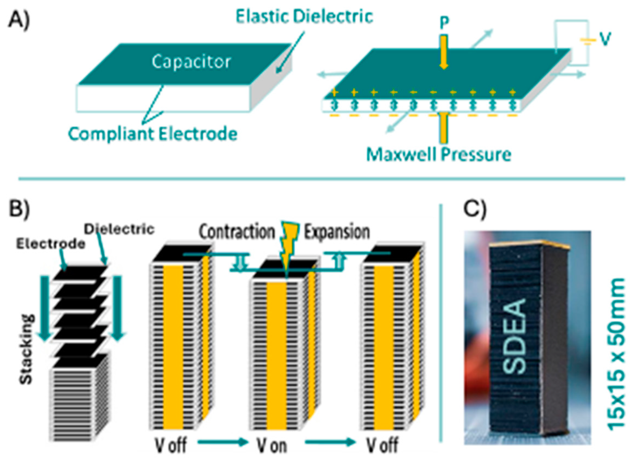
Figure 2.
The control and data acquisition block diagram of the test rig is illustrated. NI MAX was used to control the HV amplifier that drove the actuators (SDEAs) and to read the force data via the NI 9237 module. Displacement data was directly recorded through the micro-epsilon software using a laser sensor.
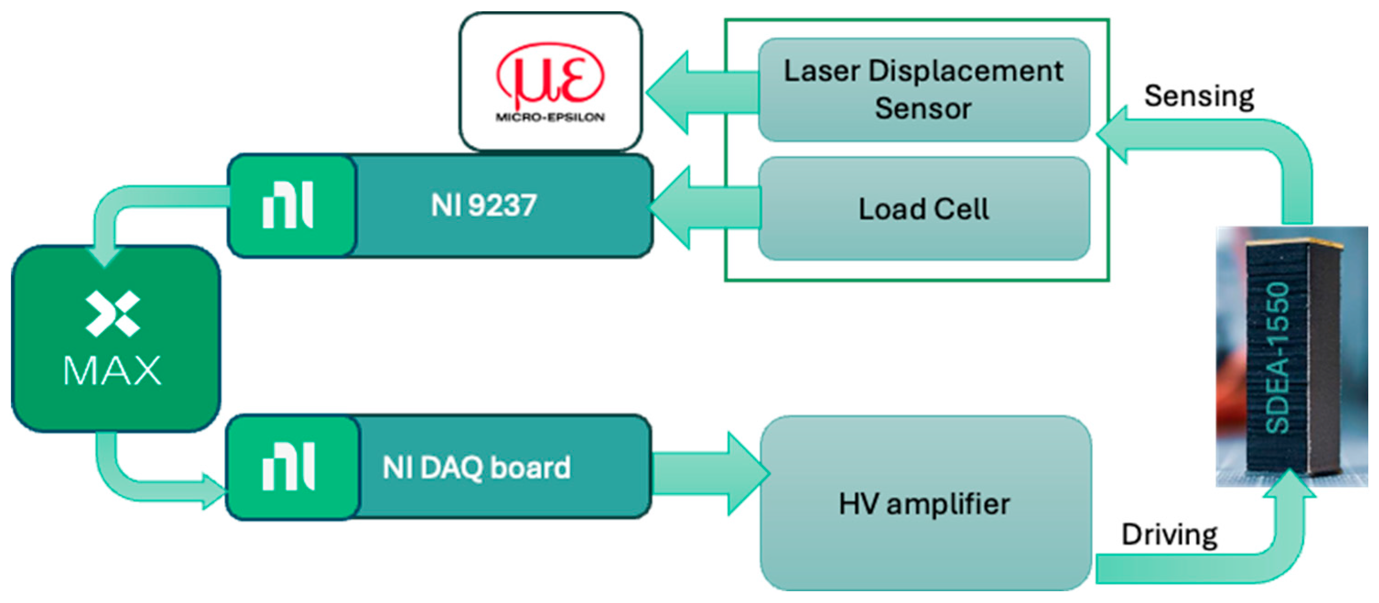
Figure 3.
The figure illustrates an actuator under isometric conditions, with one fixed end at the bottom and the other end connected to a load cell. It is crucial for the actuator to remain vertical; therefore, we used a line laser tool to ensure proper alignment and adjusted the actuator using two precision translation stages.
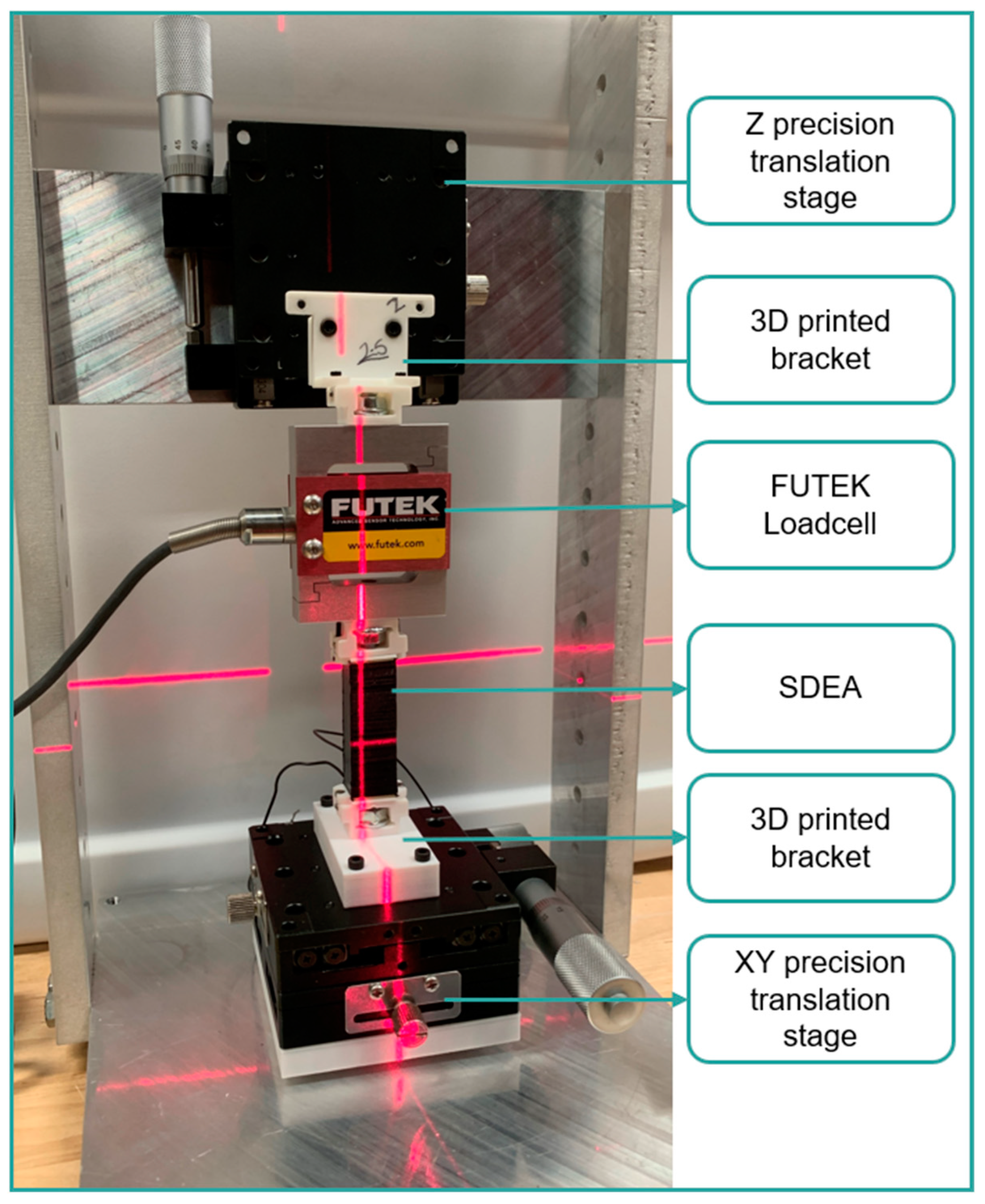
Figure 4.
The figure depicts isotonic conditions, which include: (a) fixing the actuator at the top end, hanging various loads from the bottom end, and measuring contraction using a displacement laser sensor; and (b) fixing a 1x3 configuration of SDEAs, hanging various loads from the bottom end, and measuring contraction using a displacement laser sensor.
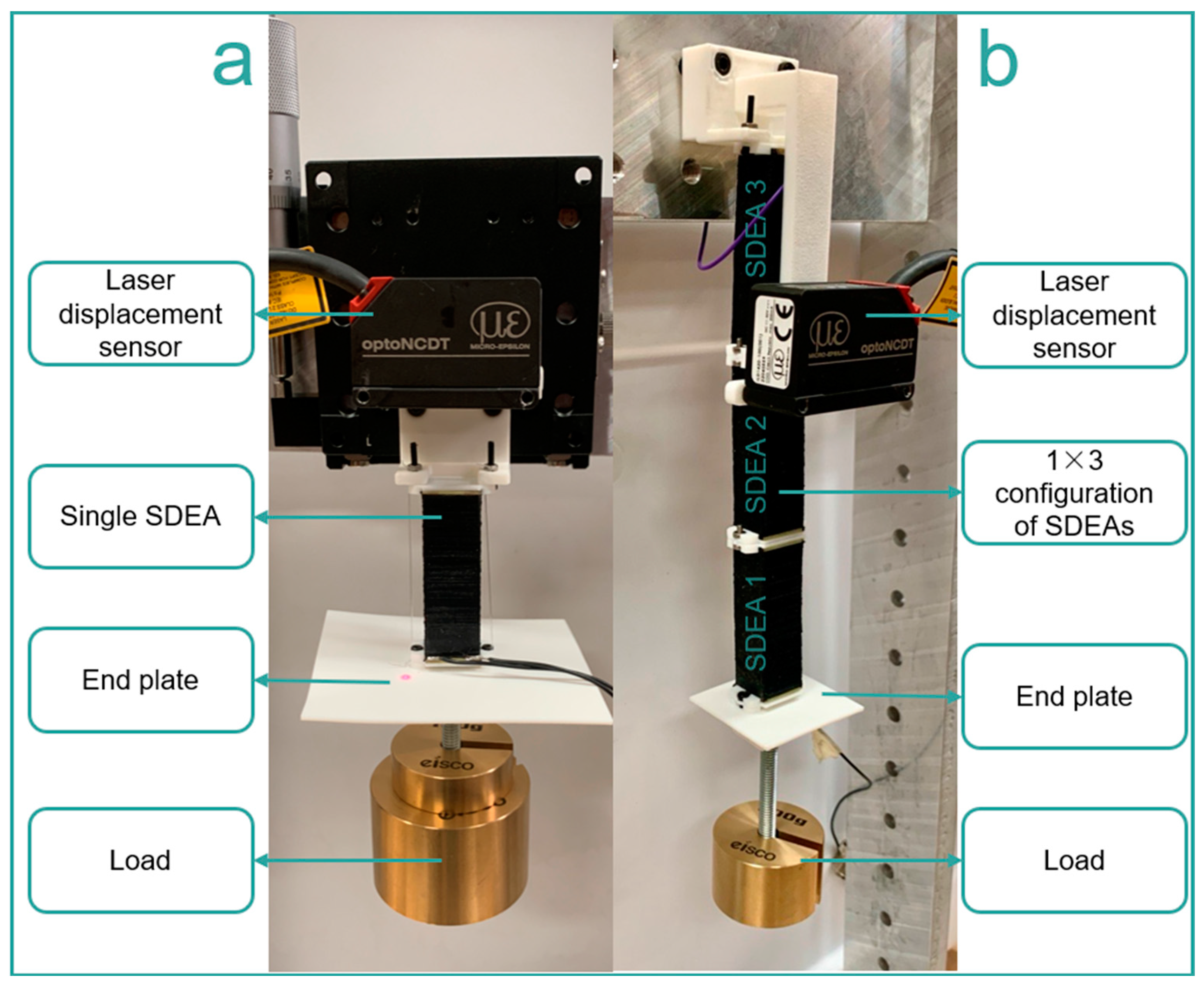
Figure 5.
The figure depics SDEAs under free-standing conditions, which include: (a) applying different voltages to an actuator fixed at the bottom and measuring contraction using a laser displacement sensor; and (b) applying different voltages to a 1x3 configuration of SDEAs and measuring contraction using a laser displacement sensor.
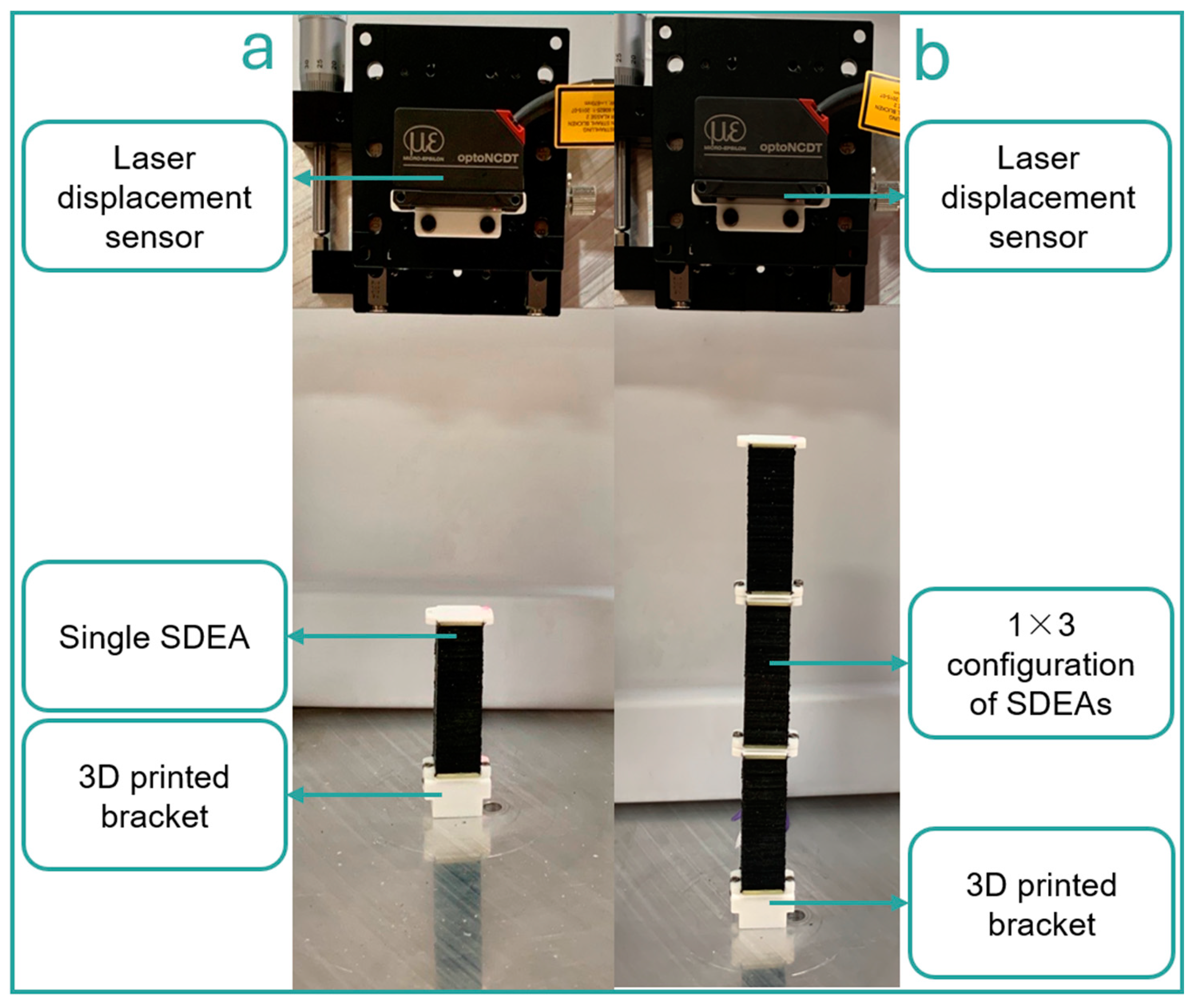
Figure 6.
The figure depicts an actuator under stiffness testing, first (a) in a horizontal orientation and second (b) in a vertical orientation. A Shimadzu universal testing machine applies a 1 mm displacement to the actuator at different voltages, and the feedback force is measured using the machine’s load cell.
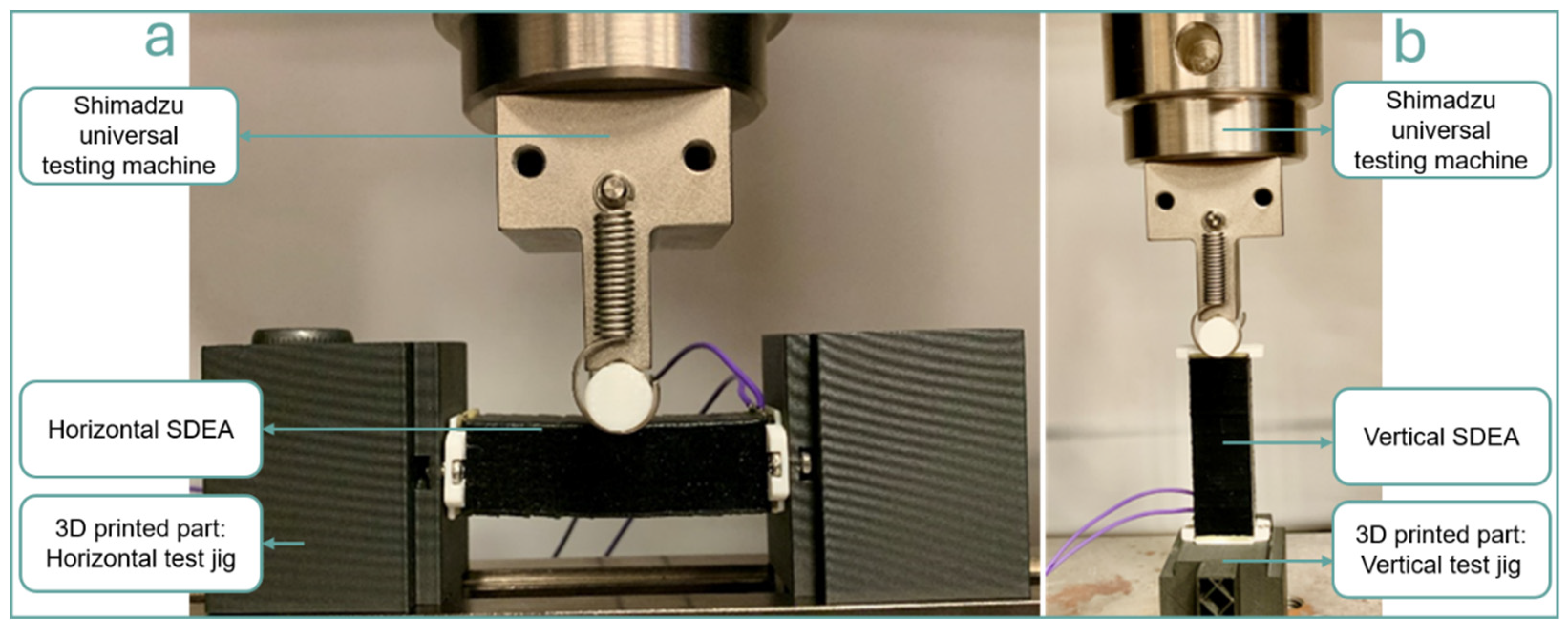
Figure 7.
The graph shows the force that each of the five actuators can generate in Isometric condition at voltages up to 1200 V.
Figure 7.
The graph shows the force that each of the five actuators can generate in Isometric condition at voltages up to 1200 V.
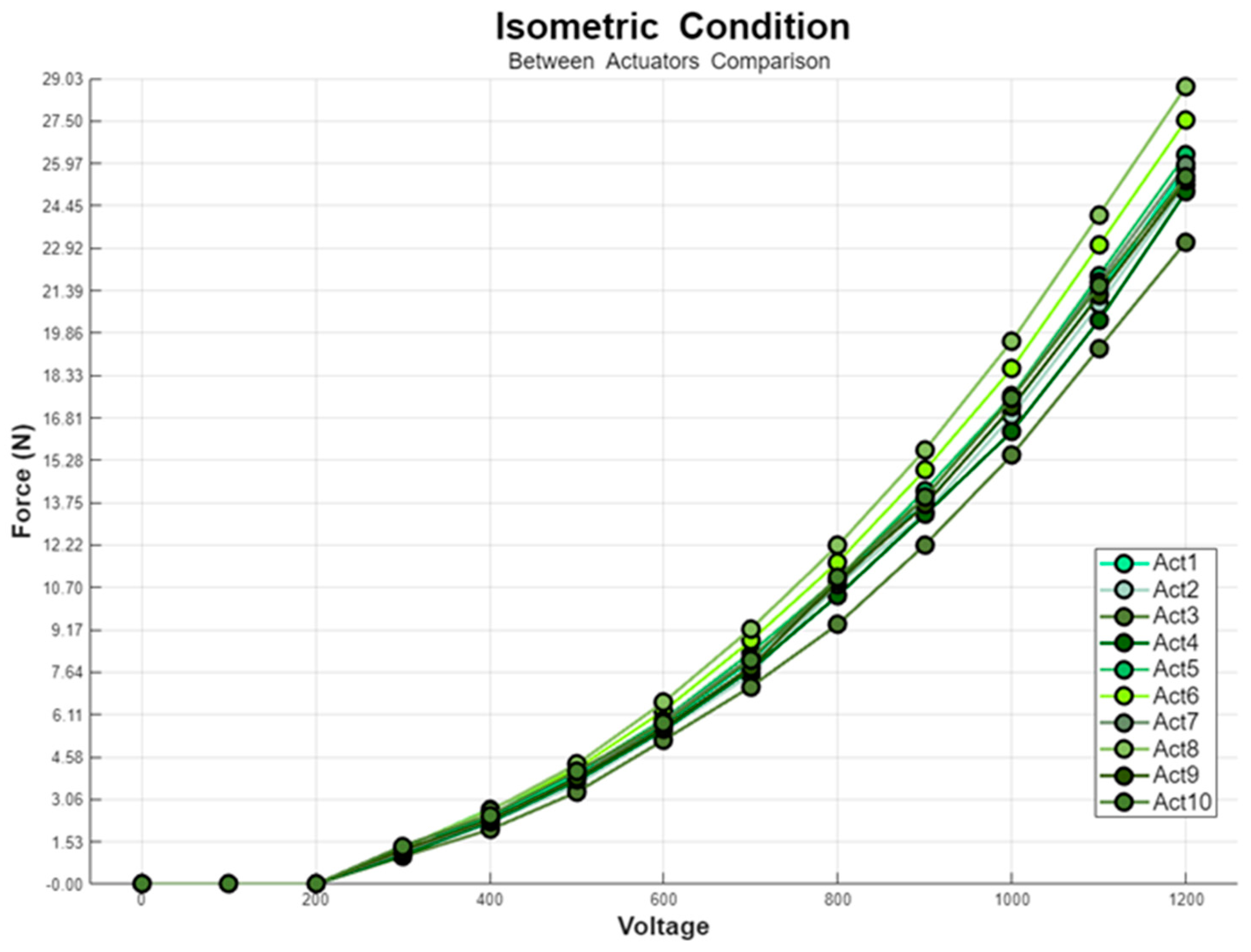
Figure 8.
The graph shows seven separate experiments on one actuator at different voltages, up to 1200 V, using loads ranging from 100 g to 700 g.
Figure 8.
The graph shows seven separate experiments on one actuator at different voltages, up to 1200 V, using loads ranging from 100 g to 700 g.
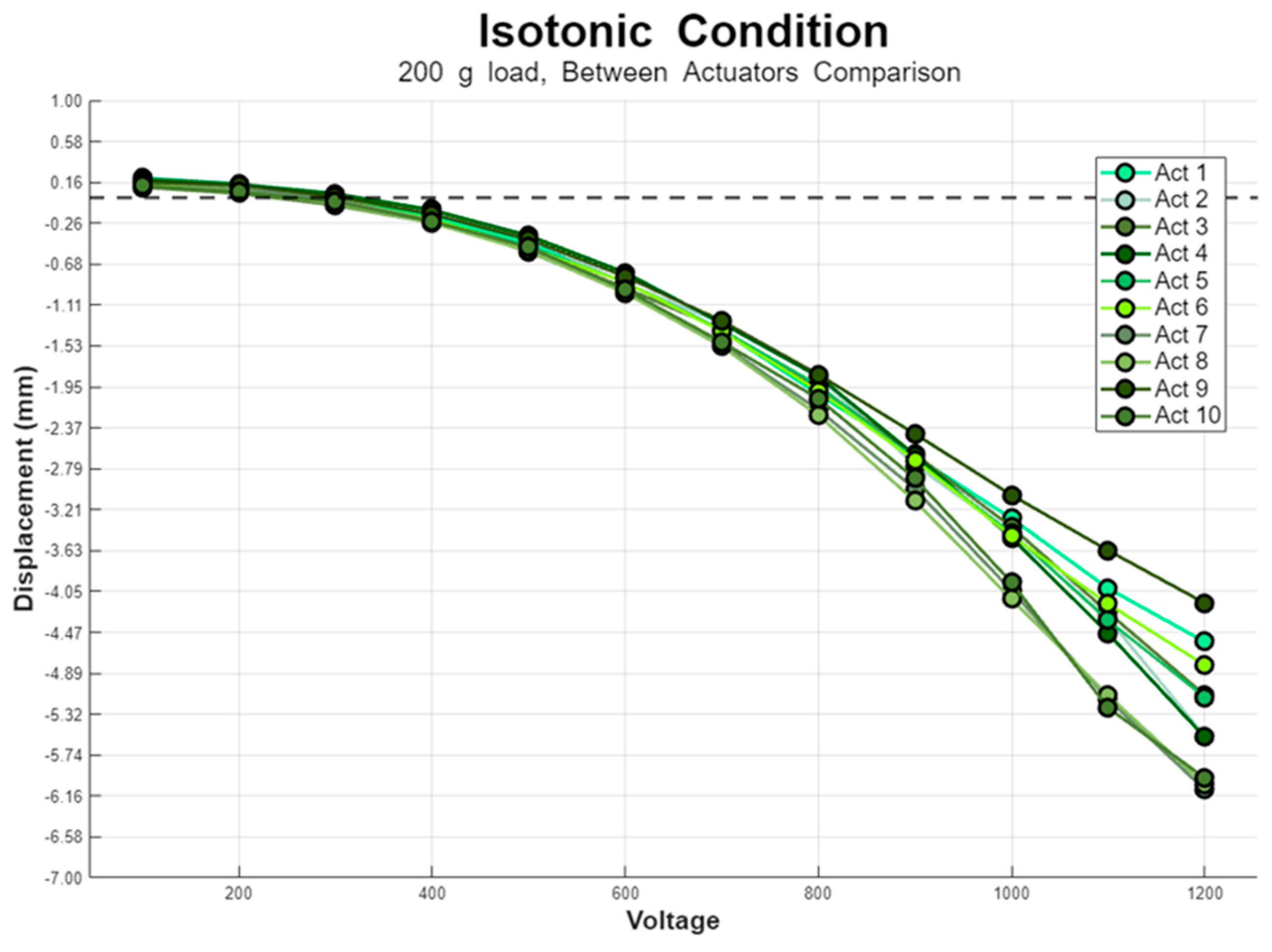
Figure 9.
The graph shows the shortening of ten different actuators under a 200 g load and various voltages up to 1200 V.
Figure 10.
The graph shows the shortening of a 1×3 configuration of DEAs under different loads, ranging from 100 g to 700 g, and voltages up to 1200 V.
Figure 10.
The graph shows the shortening of a 1×3 configuration of DEAs under different loads, ranging from 100 g to 700 g, and voltages up to 1200 V.
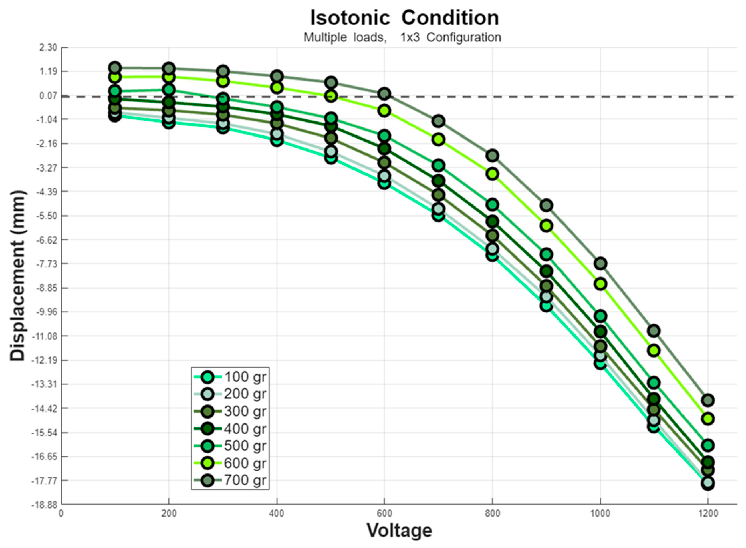
Figure 11.
The graph shows the shortening of ten different actuators under voltages up to 1200 V in a no-load condition.
Figure 11.
The graph shows the shortening of ten different actuators under voltages up to 1200 V in a no-load condition.
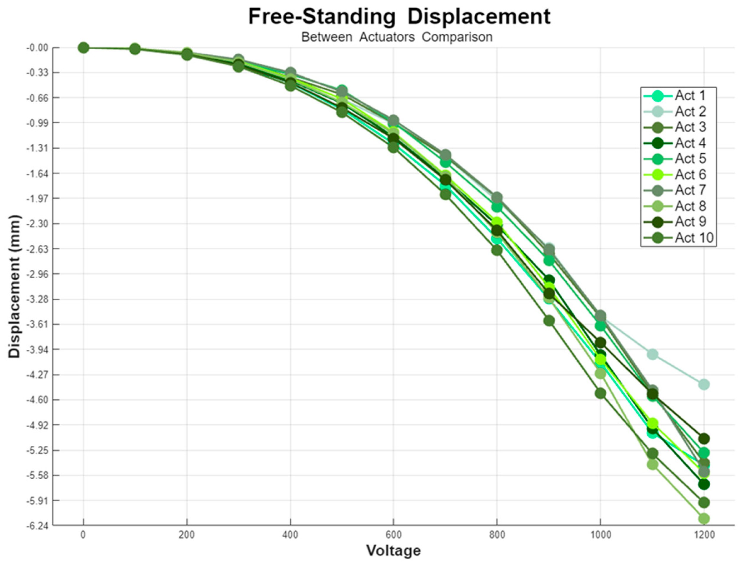
Figure 12.
The graph shows the shortening of a 1×3 configuration of DEAs under voltages up to 1200 V in a no-load condition.
Figure 12.
The graph shows the shortening of a 1×3 configuration of DEAs under voltages up to 1200 V in a no-load condition.
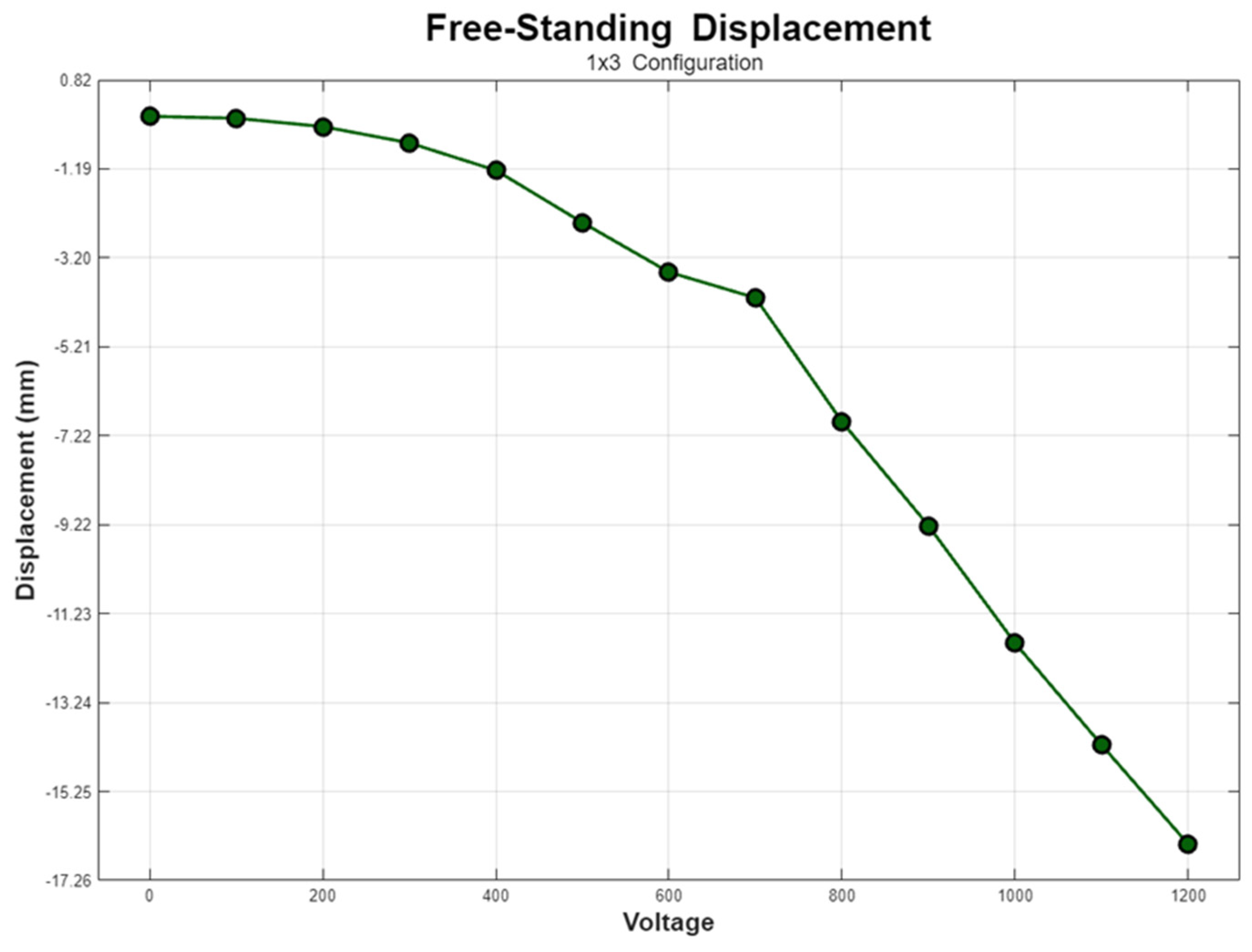
Figure 13.
The graph shows the stiffness of one actuator in the X and Y directions under different voltages, ranging from 800 V to 1200 V.
Figure 13.
The graph shows the stiffness of one actuator in the X and Y directions under different voltages, ranging from 800 V to 1200 V.
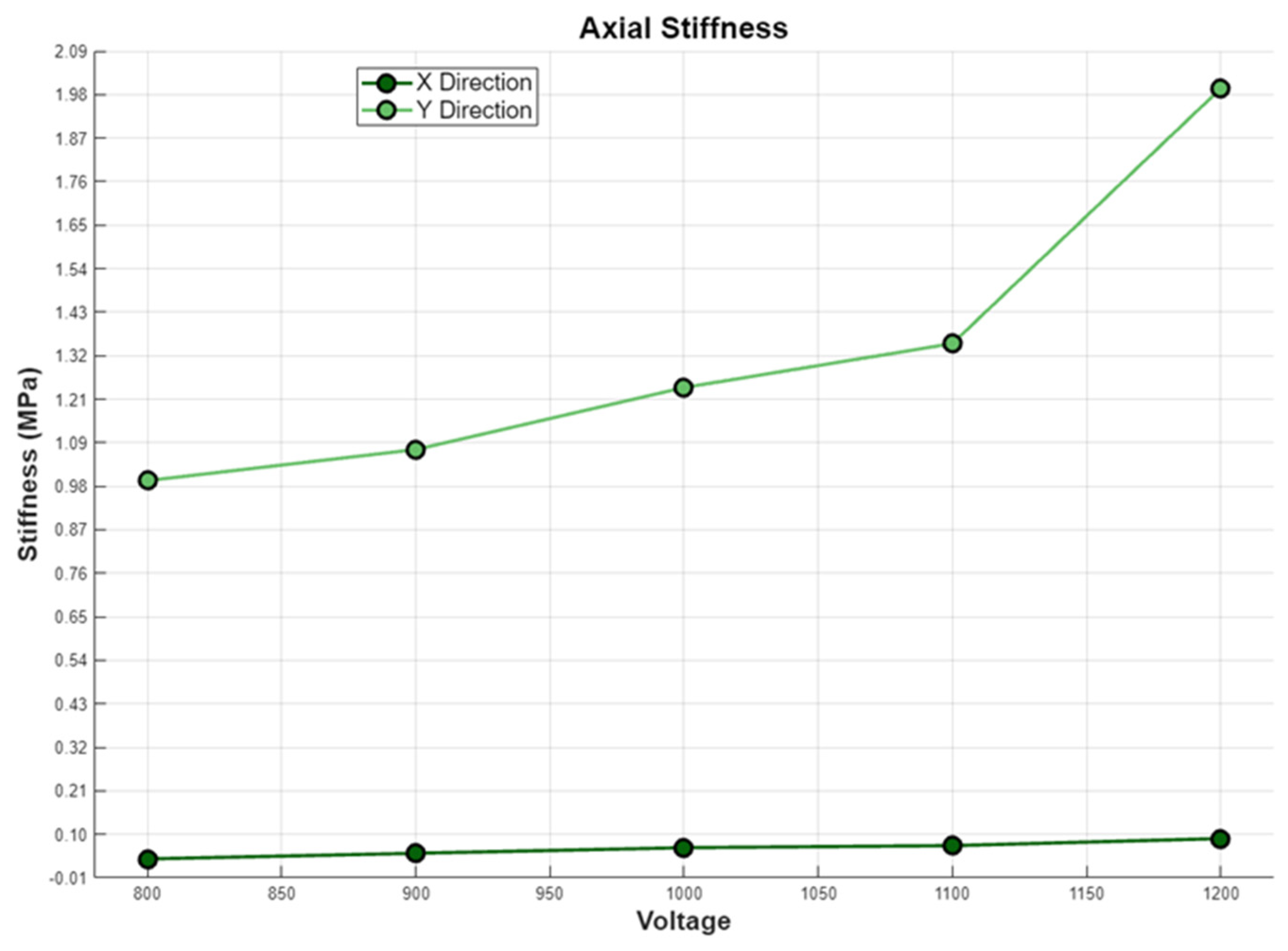

Table 1.
Properties of Freestanding DEA Configurations: Strain values are no-load; Stroke lists measurement load; Forces show isometric force; Dimensions in parentheses indicate active length.
Table 1.
Properties of Freestanding DEA Configurations: Strain values are no-load; Stroke lists measurement load; Forces show isometric force; Dimensions in parentheses indicate active length.
| Configuration | Strain | Force | Dimension(mm) | Voltage | Weight |
|---|---|---|---|---|---|
| Tubular(12) | 3 % | 100(60 active) | 2700 V | 105 g | |
| Helical(13) | 8 % | ~0.65 N | 80×13 | ~1200 V | |
| Folded(14) | 5 % | ~3 N | 85×25 | ~1000 V | |
| Stacked(15) | 18 % | 32 N | 25×20 | 4200 V | 4 g |
| Rolled(16) | 2.5 % | 0.18 N | 60x4 | 3000 v |
Table 2.
The Reported Mechanical Property of CTsystems’ CT25.0-1515-71 (CT-SDEA).
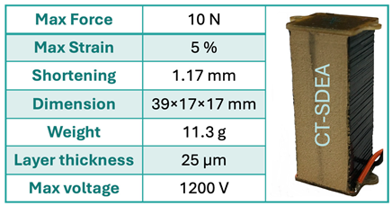
Table 3.
The measured mechanical property of SDEA-1550 at 800 v (recommended voltage) and 1200 v (recommended voltage for CT-SDEA) in comparison to our reported value for CT-SDEA(18). The presented values are the mean values; the force and shortening values are presented as mean ±SD.
Table 3.
The measured mechanical property of SDEA-1550 at 800 v (recommended voltage) and 1200 v (recommended voltage for CT-SDEA) in comparison to our reported value for CT-SDEA(18). The presented values are the mean values; the force and shortening values are presented as mean ±SD.
Disclaimer/Publisher’s Note: The statements, opinions and data contained in all publications are solely those of the individual author(s) and contributor(s) and not of MDPI and/or the editor(s). MDPI and/or the editor(s) disclaim responsibility for any injury to people or property resulting from any ideas, methods, instructions or products referred to in the content. |
© 2024 by the authors. Licensee MDPI, Basel, Switzerland. This article is an open access article distributed under the terms and conditions of the Creative Commons Attribution (CC BY) license (http://creativecommons.org/licenses/by/4.0/).
Copyright: This open access article is published under a Creative Commons CC BY 4.0 license, which permit the free download, distribution, and reuse, provided that the author and preprint are cited in any reuse.


