3.1. Wear Curve of the Saw Tooth
Starting from the tool life of 0.08 m
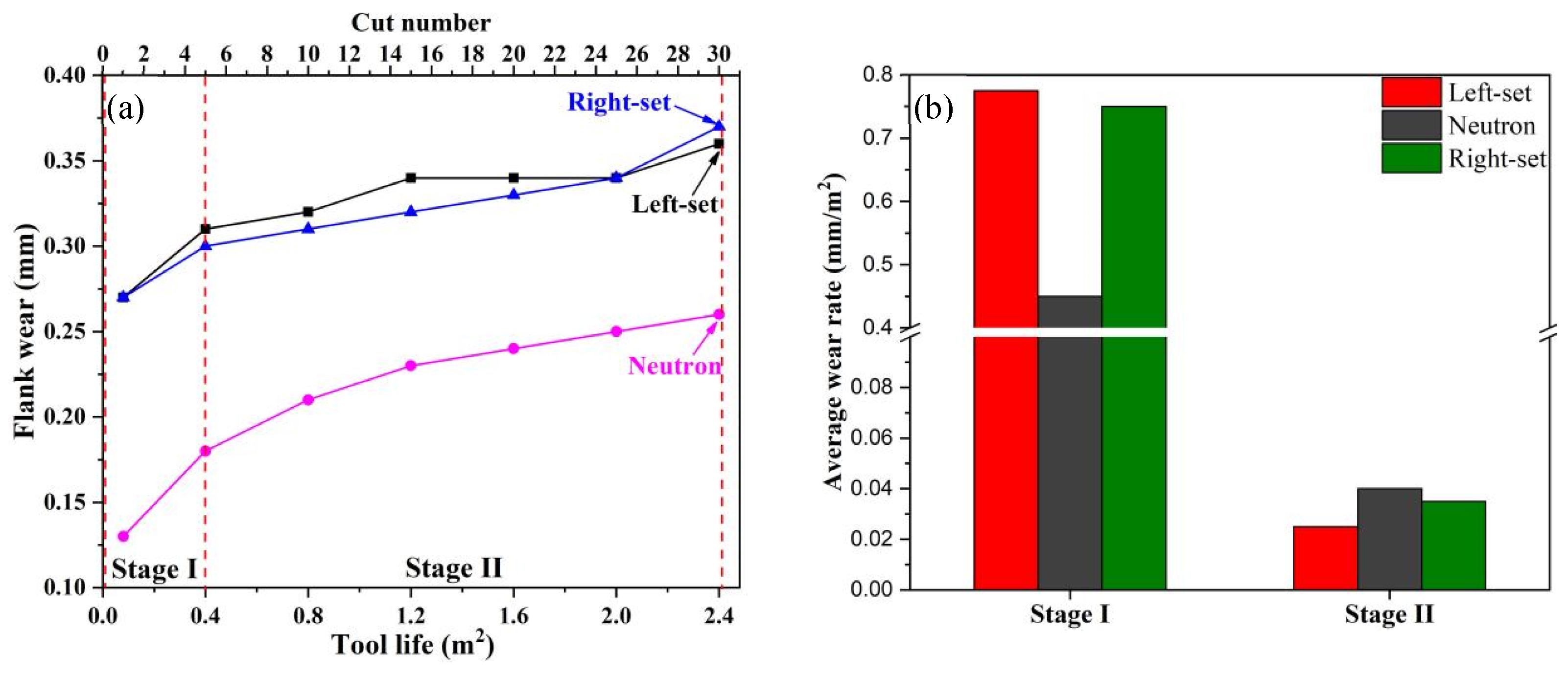
2 (the first cut), the bandsaw was removed off after every five cuts for flank wear measurement. The wears of the neutron, left-set, and right-set teeth were measured individually, and the wear curves are shown in
Figure 4a. The bandsaw employed in the sawing test finally fails after sawing 2.4 m
2, and the failure mode is out-of-square due to the large wear of the teeth. The flank wears of the neutron, left-set, and right-set tooth reach 0.26 mm, 0.36 mm, and 0.37 mm, respectively.
As shown in
Figure 4a, the flank wear of the neutron tooth is less than that of the set tooth due to the shape characteristics of different teeth. The wears of both the neutron and set teeth are divided into two stages: Stage I—sawn area below 0.4 m
2, and Stage II—sawn area over 0.4 m
2. When the sawn area reaches 0.4 m
2, the flank wears of the neutron, left-set, and right-set tooth are 0.18 mm, 0.31 mm, and 0.30 mm, respectively, which are 69.2%, 86.1%, and 81.1% of those of the failed bandsaw, while the tool life percentage at this time is only 16.7% (= 0.4/2.4 × 100%). After the sawn area exceeds 0.4 m
2, the tooth wear enters into Stage II, when the wear rate decreases significantly. The average wear rates of the neutron, left-set, and right-set teeth at Stage II are 0.04 mm/m
2, 0.025 mm/m
2, and 0.035 mm/m
2, respectively, which are largely lower than those at Stage I (as shown in
Figure 4b).
Common tool wear curves are characterized by three stages: rapid wear in the first stage, uniform wear in the second stage, and severe wear in the later stages [
18,
19]. However, in this study, the bandsaw teeth does not exhibit severe wear in Stage III. Bandsaw blades are flexible cutting tools and fail mainly because of out-of-square or body fracture. When teeth are severely worn, the feed force increases, forcing saw blade body to bend. When the bending reaches a critical value, out-of-square wear will occur. At this time, the tooth wear has not entered into Stage III (severe wear stage). If out-of-square wear did not occur, the saw teeth would be violently worn (the third stage of wear), called as “domino stripping of teeth” phenomenon, which does not happen in this study.
3.2. Saw Tooth Wear Mechanism in Stage I
To explore the mechanism of tooth wear in Stage I, the bandsaw was removed after the first cut, and a total of 200 teeth were randomly selected for morphological observation, and significant differences were found in the wear modes of the different teeth. For the purpose of discussion, the wear modes of teeth at this stage are divided into four types.
The first type is mild wear without chipping, as shown in
Figure 5a. The vast majority of teeth are characterized by a small amount of saw tooth wear (usually flank wear below 0.1 mm), and no wear is found on a few saw teeth, indicating that they are not hurt by the workpiece. The saw teeth are relatively intact without chipping. Eleven of the 200 teeth are found to be with such characteristics, accounting for 5.5%.
The second type is significant wear without chipping, as shown in
Figure 5b. Compared with the first type, the wear of this type is larger, generally over 0.1 mm, and the built-up edge (BUE) can be observed on several teeth. However, the integrity of the teeth is good, and no chipping is found. A total of 64 teeth with these characteristics are identified, accounting for 32% of the total.
The third type is chipping, as indicated by the red arrow in
Figure 5c. In this type of wear, the chipping positions can be on the middle or corner of the teeth. The chipping width is less than 1/2 of the tooth width, usually being between 1/5 and 1/3 whatever the chipping positions are. This type of wear accounted for the largest proportion of the saw teeth (107 saw teeth, or 53.5% of the total).
The fourth type is tooth breakage, as the position indicated by the red arrow in
Figure 5d. In this type the saw tooth is seriously damaged. Both sides of the corner have large breakage, and the size is more than 1/2 of the width of the saw tooth, and in extreme cases, a complete broken saw tooth can be seen. A total of 18 teeth with the wear type are found, accounting for 9%.
The phenomenon is probably due to the different cutting depths, resulting in the cutting force alternations of different teeth. When a saw tooth is subjected to a large force, the third and fourth wear types are inclined to occur, and when a saw tooth is subjected to a small force, the first and second wear types are more likely to occur. To verify the assumption above, high-speed photography was used to obtain a real-time picture for in situ observation during bandsawing by a new saw blade, as shown in
Figure 6. Large differences were found in the cutting depths of different teeth. Some of the teeth had larger cutting depths and formed thicker chips, as shown in
Figure 6a. In this case, the cutting force of the teeth was high, causing significant wear or chipping, and in extreme cases, tooth breakage could occur. The cutting depth of some of the teeth was relatively small, and the formed chip was fine and thin, as shown in
Figure 6b. In this case, the cutting force was relatively small, the corresponding wear was mild, and the saw teeth were only slightly worn, as shown in
Figure 5a. In the high-speed photographic observations, a few teeth were found not to be in contact with the workpiece, as shown in
Figure 6c, and thus did not cut the workpiece; consequently, tooth wear did not occur.
This phenomenon is probably due to the bandsaw processing accuracy. For bimetal bandsaws, the teeth are usually shaped by a milling cutter followed by a setting process to form neutron teeth, left-set teeth, and right-set teeth. In the case of milling, production is stroke by stroke rather than continuous, where the stroke length is determined by the length of the milling cutter, and a joint is formed between two adjacent strokes [
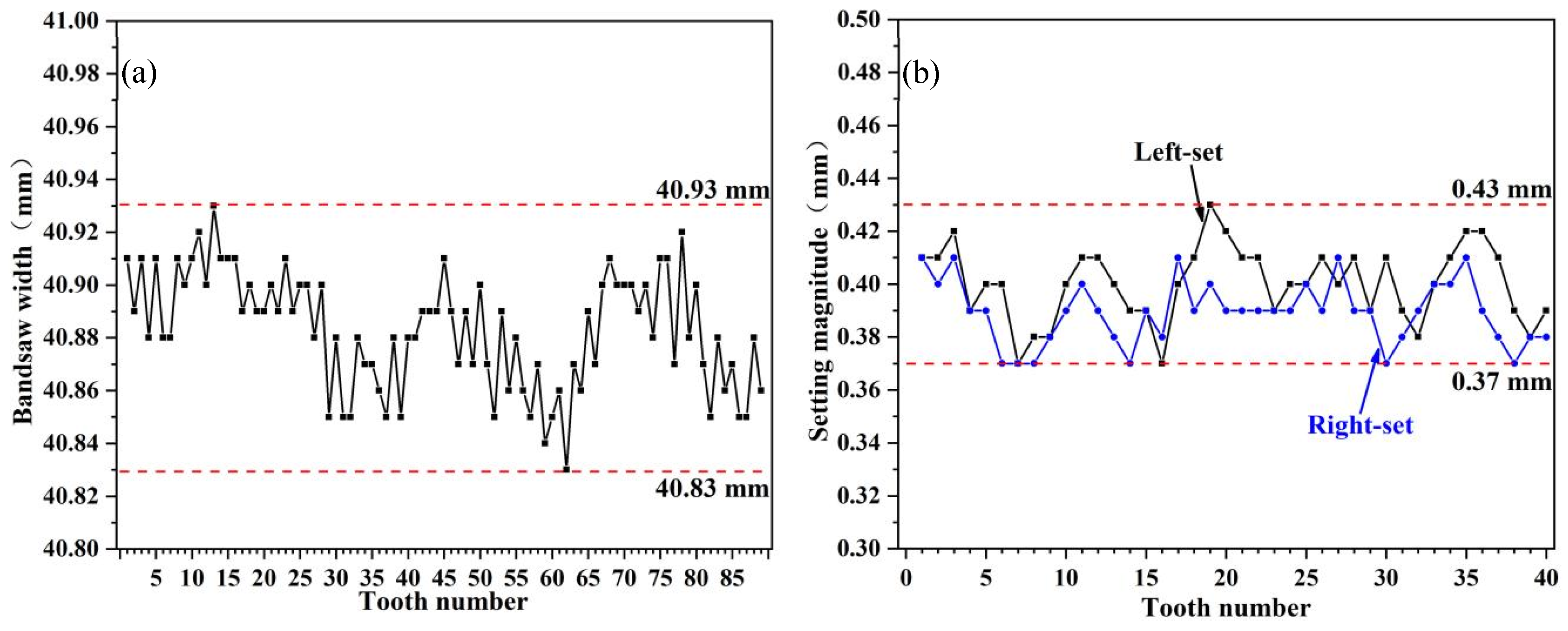
20]. The accuracy of the joint will affect the accuracy of the bandsaw. Meanwhile, the milling cutter will also experience wear during use, and as the milling cutter edge becomes worn, the width of the bandsaw during formation processing will change (usually, the width will gradually increase). The milling cutter needs resharpening when worn to a certain extent, and the width before and after resharpening is likely to alter. All these factors will affect the accuracy of the bandsaws. Similarly, tooth setting processing is affected by several factors, such as equipment rigidity, operator experience, and wear of the setting tool. To determine the deviation of the width of the bandsaw (distance from the tooth tips to the bottom edge) and the actual accuracy of tooth setting magnitude, the widths of 89 consecutive teeth of the new saw blade, setting magnitude of 40 consecutive left-set teeth and 40 consecutive right-set teeth were measured, which are shown in
Figure 7. The width of the bandsaw fluctuates from 40.83 mm to 40.93 mm, i.e., within a tolerance of 0.1 mm (as shown in
Figure 7a), and the setting magnitude varied from 0.37 mm to 0.43 mm, i.e., within a tolerance of 0.06 mm (as shown in
Figure 7b). The average cutting depth per tooth is usually small [
21] and is only 0.0025 mm in this study, which is only 1/40 of the width fluctuation range and 1/28 of the setting fluctuation range. Fluctuations in the width and setting magnitude are inclined to result in different cutting depths of different teeth. The tooth with a relatively small width and small setting magnitude withstands a small cutting depth, and in contrast, a large cutting depth occurs on the tooth with a relatively large width and small setting magnitude, which is easily chipped or broken.
As a multi-point cutting tool, the cutting depths and forces on different teeth of a new bandsaw should ideally be uniform. However, the actual cutting depths and forces of different teeth varied due to the processing accuracy of the bandsaw. Thus, the saw teeth were worn in different types. For most of the saw teeth, because of the relatively large cutting depth, the cutting resistance was large, so the saw teeth wore quickly, and chipping or breaking tended to occur. Chipping is the main wear type, and it is the main reason for the rapid wear of the bandsaw blade in Stage I. After Stage I (rapid wear), the wear of saw teeth entered Stage II (stable wear) due to the relatively even saw teeth after worn in Stage I.
3.3. Saw Tooth Wear Mechanism in Stage II
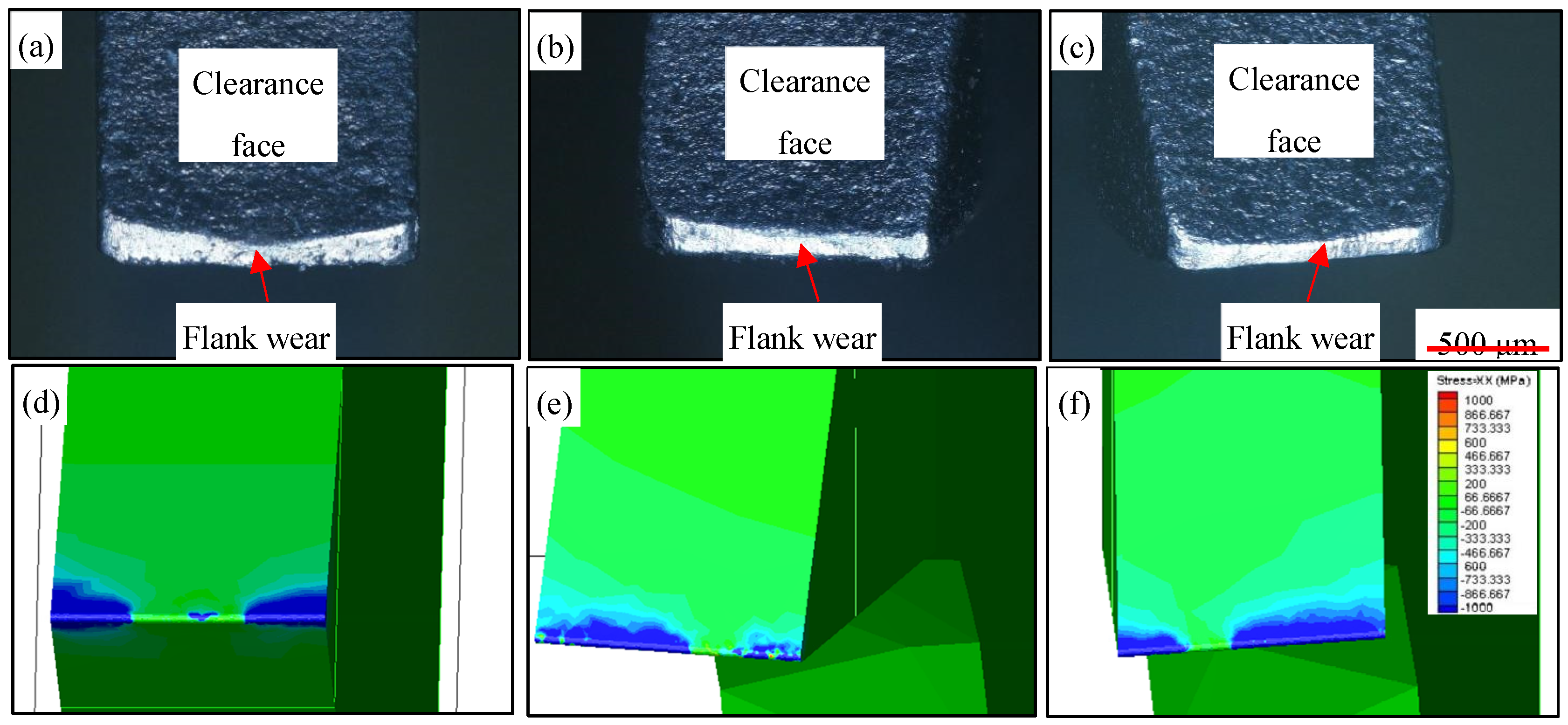
When the saw tooth wear enters Stage II, the different saw teeth become even until the bandsaw blade fails. Except for seriously damaged saw teeth (the fourth type) in Stage I, most of the remaining saw teeth eventually present uniform wear, as shown in
Figure 8a–c. However, because of the specificity of the distribution of the bandsaw blade teeth, the wear characteristics of different teeth are distinguished. For neutron tooth, both sides of tooth are worn more severely than the central part of tooth, forming an arc shape after uniform wear, as shown in
Figure 8a. For the set tooth, the major part that withstands wear is the outside of the saw tooth, that is, the left side of the left-set tooth and the right side of the right-set tooth. Therefore, wear mode of the set tooth is mainly unilateral wear, as shown in
Figure 8b,c, which meets the results of research by Sӧderberg et al. [
22].
Figure 8d–f show the stress fields of different saw teeth obtained by finite element method. The main loading positions of the neutron tooth are on both sides of the cutting edge, and the stress fields on both sides are basically the same. The main loading position of left-set tooth is on the left side of the cutting edge, and the loading area on right side of the tooth is relatively small. Accordingly, the main loading position of right-set tooth is on the right side of the cutting edge, and the loading area on the left side of left-set tooth is relatively small. By comparing
Figure 8a–c and
Figure 8d–f, it can be seen that the severe worn areas of the tooth match those with relatively concentrated stress fields.
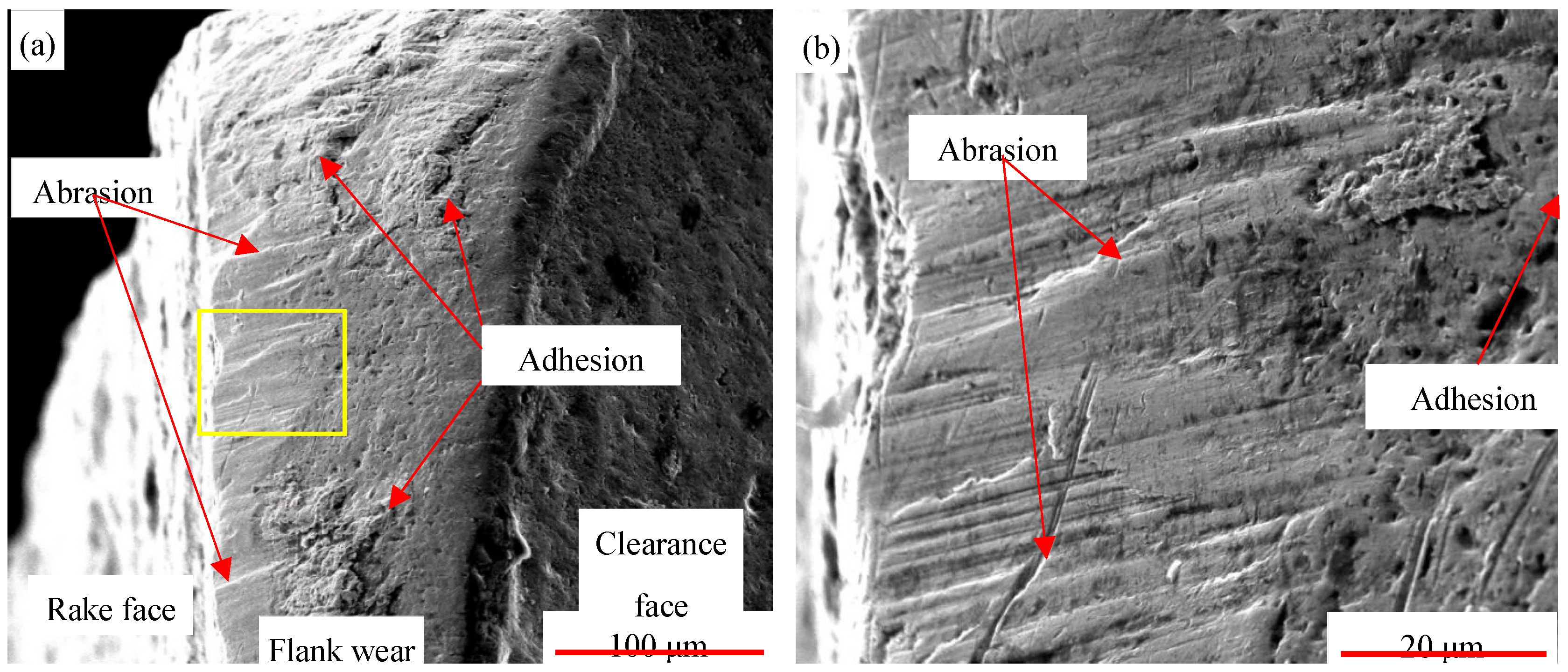
In Stage II, the saw teeth gradually become even, so chipping of the saw teeth infrequently occurs, and the wear of the saw teeth presents a wear mechanism different from that in Stage I. The SEM images of the bandsaw blade teeth after failure are shown in
Figure 9, which exhibits two different tooth wear mechanisms in Stage II. Obvious adhered workpieces are observed, and most of them are tightly adhered to the saw teeth. However, cracks can be found between some adhered workpieces and the saw teeth, indicating that they are about to peel off. The parts show the characteristics of adhesive wear. Meanwhile, small scratches exist on the worn surface of the saw tooth, and the direction of the scratches is consistent with the cutting direction, which presents abrasive wear.
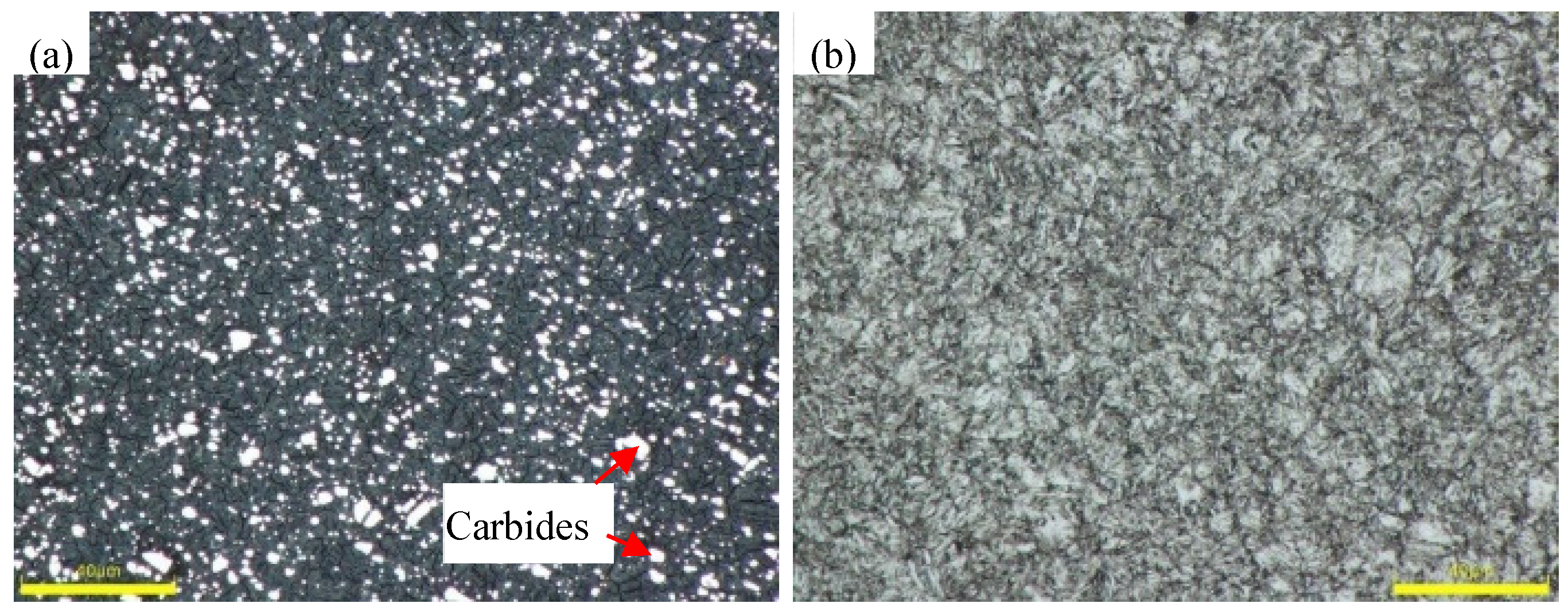
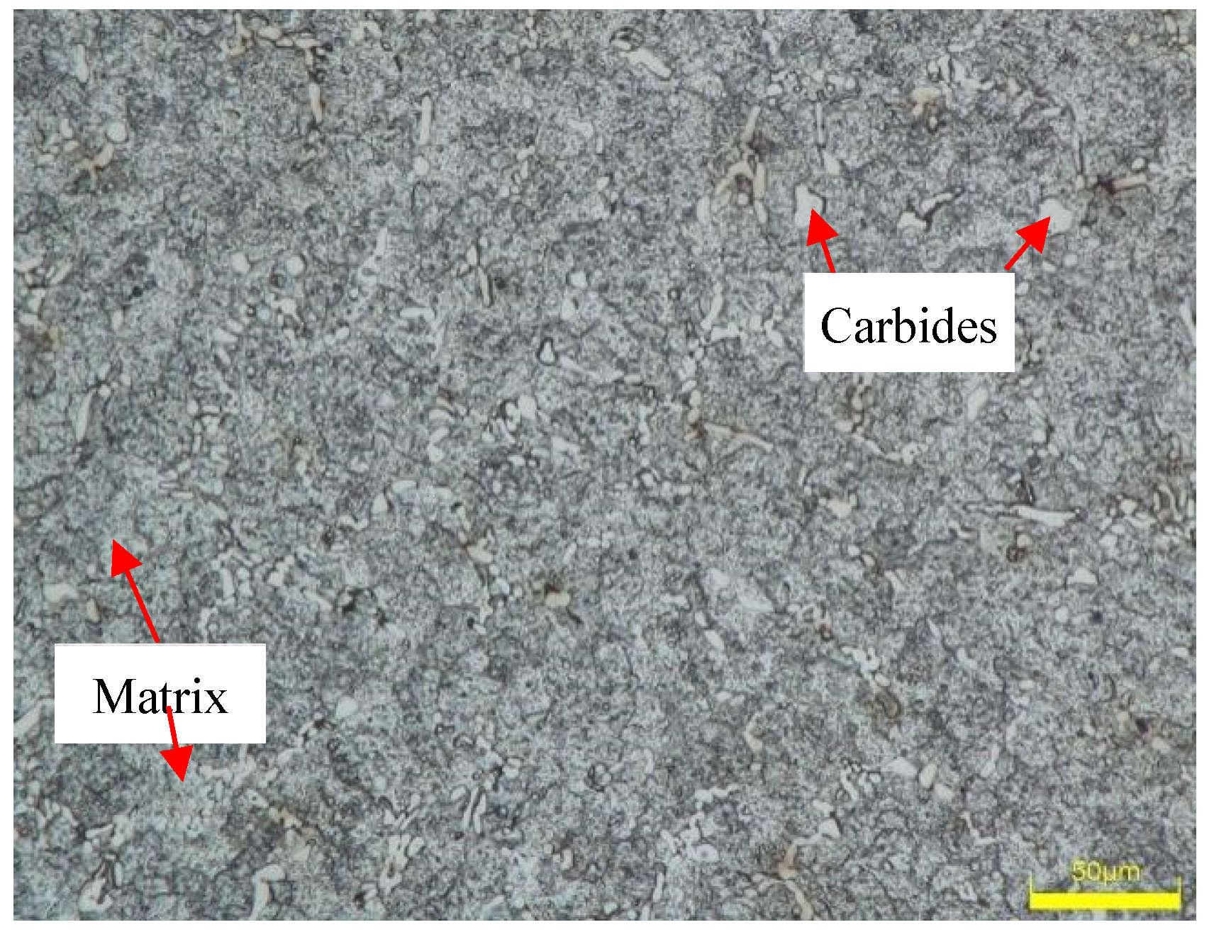
Mostly, abrasive wear is caused by the scraping of hard particles. The workpiece material (Cr12MoV cold-work die steel) used in this study is high-Cr martensitic stainless steel with a high C content of ~ 1%. There are amounts of carbides with high hardness distributing on the matrix (as shown in
Figure 2). These hard carbides abrade the saw teeth during bandsawing, which is the original of abrasive wear.
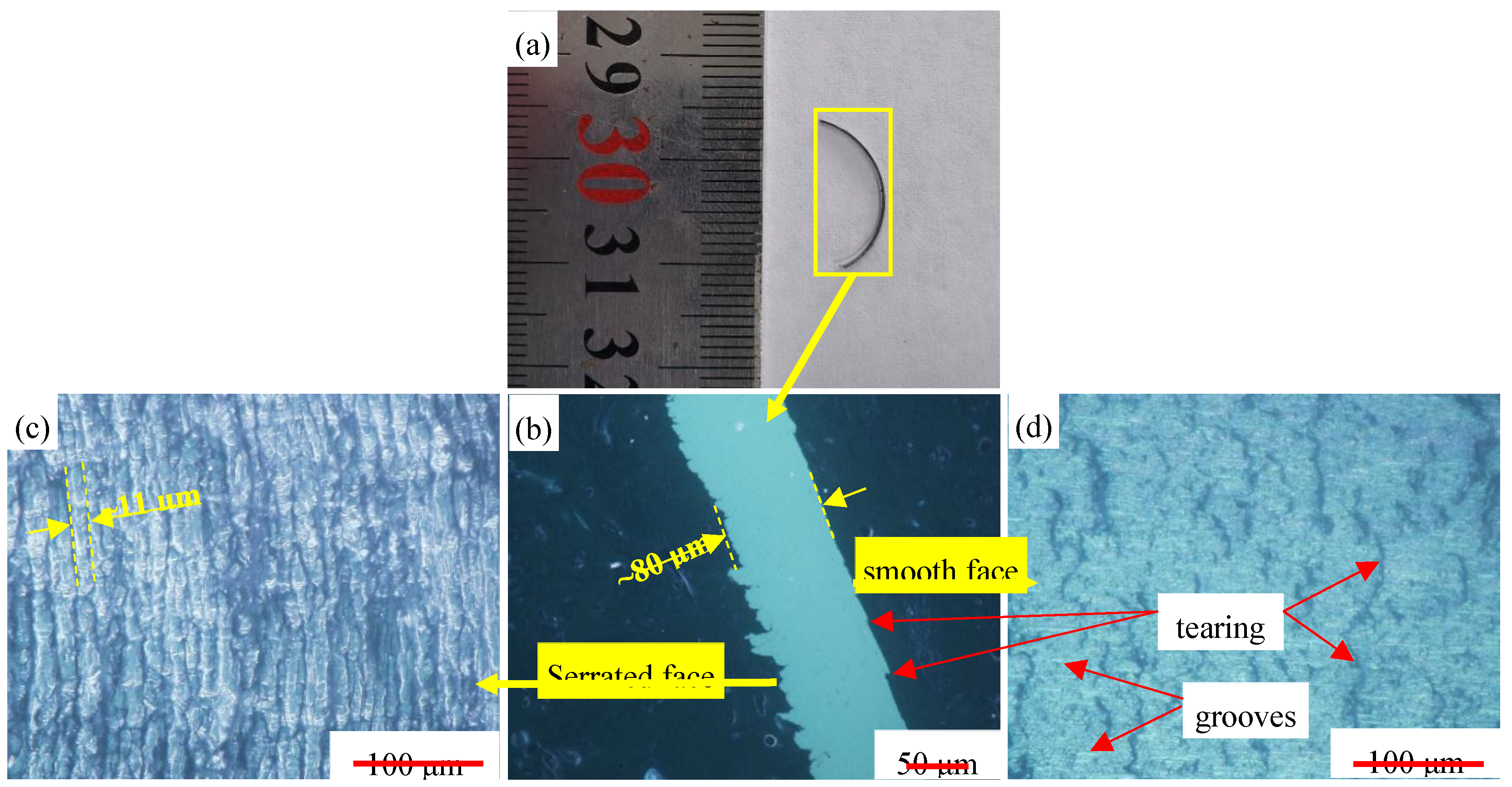
Figure 10a is the photo of a typical chip formed in Stage II, and
Figure 10b is the picture showing details of the chip in
Figure 10a. The chip thickness is about 80 μm, which is 32 times of the average cutting depth. One side of the chip is irregularly serrated, with the space between two adjacent serration of about 11 μm, as shown in
Figure 10c. The serrated side is the curved surface of the chip and does not contact with the saw edge. The other side of the chip is a smooth surface, which is in contact with the saw tooth and forms a secondary deformation zone during the sawing process, which is subjected to great shear stress due to the friction between chip and tooth. Small grooves can be seen on the smooth surface, which are formed by the scraping of the fine carbides in the high speed steel. In
Figure 10b,d, obvious tearings can be seen on the smooth surface, and their length and spacing are not significantly regular, suggesting that the tear on the chip surface is formed randomly. The workpiece Cr12MoV adopted in the test was annealed to a hardness of about 267 HV, composed of hard carbide and soft steel matrix. Cutting temperature can reach 300~400 ℃ due to the heat generation during bandsawing. The heat makes the soft steel matrix of the workpiece very adhesive and a part of the matrix adheres on the tooth. The adhered chip may be peeled off from the tooth under the large shear stress. By the action of the adhering-peeling cycle, the chips will form irregular tearings on the smooth surface, as well as adhesive wear on the saw teeth.
3.4. Suggestions for Improving the Sawing Performance of Bandsaws
As mentioned above, the wear of bandsaw teeth when sawing Cr12MoV was divided into two stages: Stage I-rapid wear stage, during which the dominant wear mechanism was chipping with flank wear and tooth breakage coexisted; and Stage II-homogeneous wear, during which adhesive and abrasive wear were the main wear mechanisms. Therefore, suppressing chipping in Stage I and adhesive and abrasive wear in Stage II are the main strategies for improving the sawing performance of bandsaws.
Edge preparation of saw teeth by sandblasting was previously proposed to reduce the previous chipping of bandsaw teeth [
23,
24]. Since bandsawing features a small cutting depth of a single tooth (the average cutting depth of a single tooth in this study was 2.5 μm, while the cutting depths of other methods such as turning, drilling, and milling were usually more than 100 μm [
25,
26,
27]). The edge radius of bandsaws shall not be too large, which is distinguished from other cutting tools. The main reason for chipping in Stage I is the large tolerance of the processing accuracy of the bandsaw blade (greater than the cutting depth of a single tooth); thus, improving the processing accuracy of the bandsaw blade is an effective way to reduce chipping. A method to manufacture a bimetal bandsaw blade by CNC grinding instead of milling was proposed to improve the width accuracy of the bimetal bandsaw blade from 0.1 mm (as shown in
Figure 6a) to ≤0.05 mm [
28]. Break-in procedures are widely used in bandsawing, especially for hard-to-machine materials with work-hardening rate, such as stainless steel and superalloys. When executing the break-in procedure, the operator needs to decrease the feed rate to reduce the average cutting depth per tooth to reduce the cutting force. Then, the feed rate is increased gradually to the normal value after break-in. However, there are many factors that will influence the break-in procedure, such as the bandsaw’s quality, stability of the bandsaw machine and workpiece. Operators generally perform the break-in procedure based on their own experience.
Adhesive and abrasive wear are the main wear mechanisms of Stage II, so improving the wear resistance of the saw teeth is beneficial for reducing the wear during Stage II. The application of powder metallurgy HSS instead of traditional HSS is effective. For example, ASP2042 [
29] and ASP2051 [
30] are better options for saw tooth materials. PVD technology has been broadly used for various tools, such as lathing tools, milling cutters, drills, and circular saws. Researchers have tried to apply PVD technology to improve the sawing performance of bandsaws, and the life of bandsaws has been obviously improved [
14]. However, unlike other tools, PVD coating is not widely utilized in bandsaws at present due to its high cost and the special shape of bandsaws.
