1. Introduction
Polymer-dispersed liquid crystals (PDLCs) are film-like solid composite materials comprising phase-separated liquid crystal (LC) domains and a polymer matrix. Among the multitude of phase separation methods, the most common is polymerization-induced phase separation. This method entails irradiating isotropic solutions of LCs, photocurable monomers, and a photo-initiator with ultraviolet (UV) light. Reorientation of LC molecules by applying an electric field (
E-field) to PDLCs, which are electro-optical (EO)-responsive materials, has been used in practical applications [
1,
2,
3,
4,
5]. PDLCs are generally opaque because of their optical inhomogeneity, which causes the transmitted light to scatter. Applying an
E-field to a PDLC would render it optically uniform and transparent owing to LC reorientation. Additionally, PDLCs exhibit light scattering–light transmission switching upon turning the
E-field off and on, respectively. This characteristic enables their application as light-regulating materials. Transparent PDLCs (nano-PDLCs), even in the absence of an applied
E-field, can be obtained by reducing the LC weight fraction in the raw material while increasing the UV irradiation intensity to form a phase-separated structure smaller than the visible wavelength. Nano-PDLCs, such as those with suppressed random light scattering, have been proposed as attractive EO-responsive materials [
6,
7,
8,
9,
10,
11]. While general PDLCs switch between light scattering and transmission with
E-field off and on, respectively, nano-PDLCs are initially optically isotropic because of the random orientation of the LC molecules. However, when an
E-field is applied, the LCs reorient and macroscopic birefringence is induced, exhibiting an electro-birefringence effect. The EO responsivity of nano-PDLCs is also based on the reorientation of LC molecules inside the LC domain by the applied
E-field. Because of the smaller size of the LC domains, nano-PDLCs require a stronger
E-field than do general PDLCs for driving because of the large specific surface area of the LC/polymer interface and also the strong influence of interface anchoring. High voltages are required to drive nano-PDLCs. Therefore, attempts have been made to lower the driving voltage by doping nano-PDLCs with conductive materials, [
12,
13,
14] such as low-
Tg polymers [
15]. Recently, we realized a transparent PDLC by using a highly polar nematic (N) LC mixture, DIO [
16], and its analog compounds. These compounds exhibit large dielectric anisotropy (Δ
ε) values and induce birefringence at low driving voltages. The induced birefringence was partially maintained even after the removal of the
E-field (memory effect) [
17]. In a previous study, the birefringence viewed from the substrate’s normal direction was reversibly erased by switching the electrical circuit with a relay switch and applying an
E-field in the out-of-plane direction of the substrate. Nano-PDLCs exhibit electro-birefringence effect, which is based on the reorientation of LC molecules; the memorized birefringence (up to 50% of induced birefringence) is also derived from the retention of the molecular orientation. The orientation memory effect of LC molecules after the removal of the
E-field is expected to be more stable in layered structures with mechanical stability and in highly viscous smectic (Sm) LC phases; consequently, Sm LC-based memory-type PDLCs have also been reported [
18,
19,
20]. In general, the LC molecules in the smectic A (SmA) phase form a layered structure and are more viscous than those in the N phase. Therefore, the threshold voltage required for reorientation by the
E-field for the SmA phase is higher than that for the N phase. However, the high elastic modulus also suppresses the relaxation of the molecular orientation after the removal of the
E-field. Therefore, we focused on SmA LCs with high dielectric constants parallel to the LC director. Among the aforementioned DIO analogues, several molecules have been reported to exhibit a ferroelectric SmA (SmA
F) phase with spontaneous polarization parallel to the LC director and dielectric constants reaching several hundred or higher [
21,
22]. Development of materials that can be driven at voltages lower than the driving voltages of conventional SmA LC-based materials, while exhibiting better retention of molecular orientation than N LCs, can be achieved by using SmA LC materials with greater dielectric anisotropy than that of conventional materials. In this study, we fabricated a transparent PDLC by using a SmA
F LC, EST (previously referred to as EST-4 [
22]). The structure and physical properties of the fabricated PDLC were assessed, and the impact of memory effect on the electro-birefringence was investigated.
3. Results and Discussion
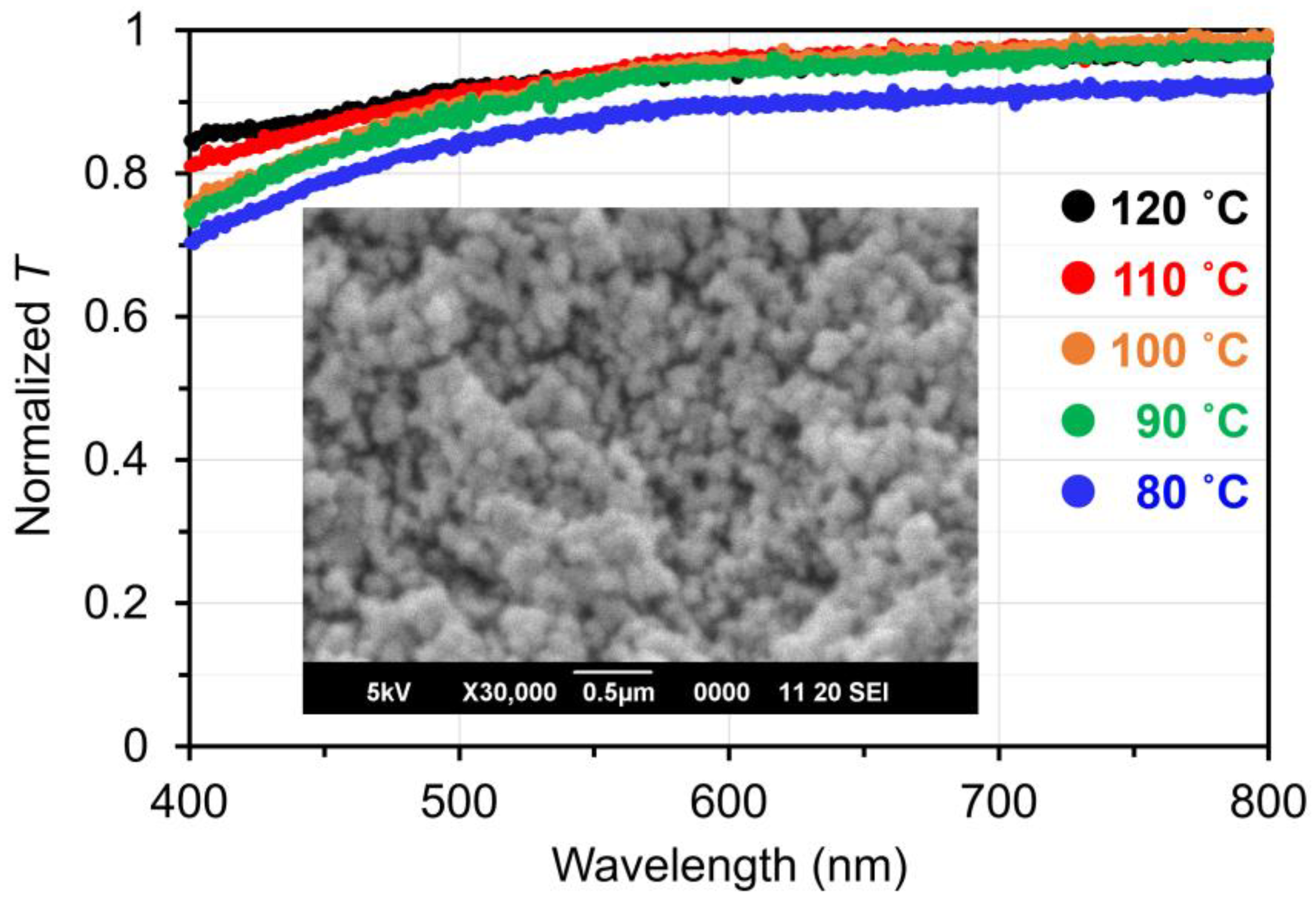
At temperatures over 80 °C, where EST exhibits LC phases, the PDLC exhibited higher normalized transmittance (
T > 0.7), suggesting the formation of phase-separated structures smaller than visible light wavelength (
Figure 2). Furthermore,
T was found to decrease with decreasing temperature. This decrease in
T can be attributed to the slight coarsening of the phase-separated LC domains due to the lowering of the compatibility between the EST molecules and polymer matrix with decreasing temperature. The SEM images show a phase separation of approximately 60–120 nm in size with a polymer ball-type morphology (
Figure 2 inset and
Figure S1 in the Supporting Information). LC droplet structures have not been observed in the memory PDLCs with micrometer-sized phase-separated structures [
23]. However, a similar polymer morphology was observed in this study.
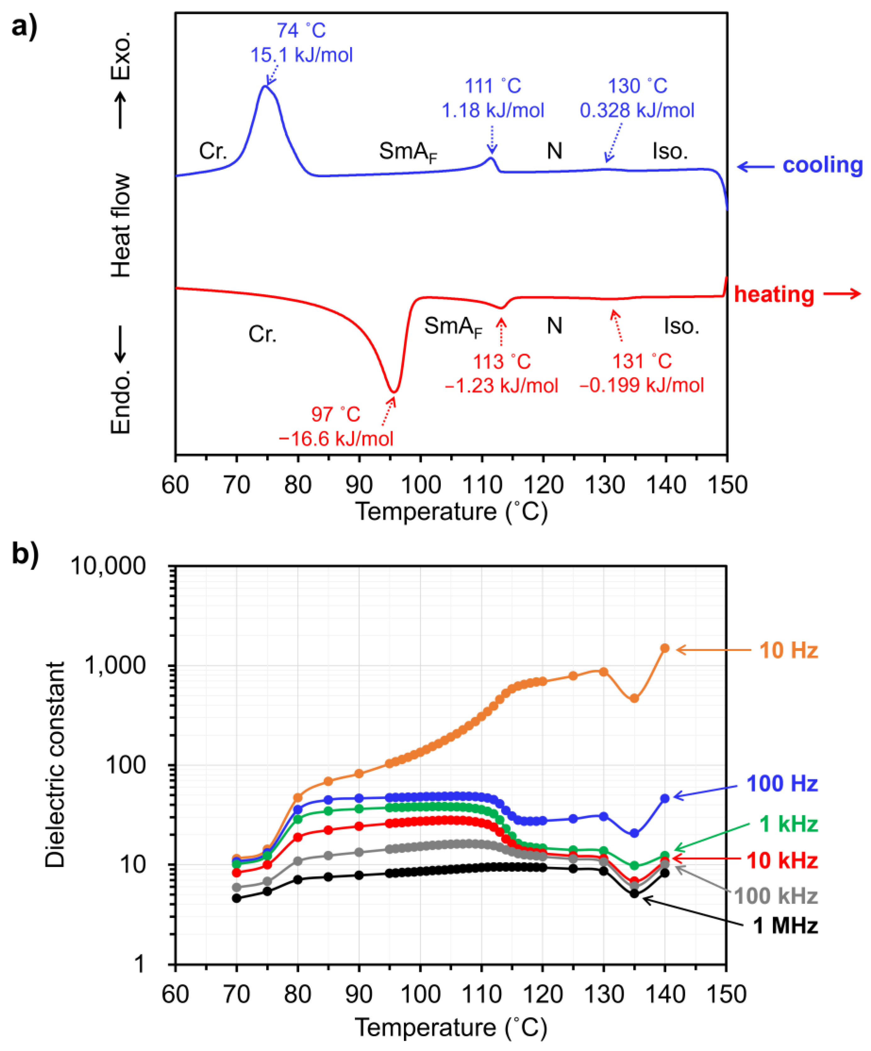
All the observed phase transition points, both during heating and cooling, shifted toward lower temperatures than those of the bulk EST [
22]. In the cooling step, exothermic peaks were observed at 130 °C (Iso. to N), 111 °C (N to SmA
F), and 74 °C (SmA
F to Cr.), depending on phase transition (
Figure 3A). Furthermore, the phase transition enthalpy of EST in the PDLC were clearly lower than that of the bulk—0.328 kJ/mol, 1.18 kJ/mol, and 15.1 kJ/mol, which were 78%, 45%, and 56% of that of the bulk, respectively. The small apparent enthalpies of phase transition observed in the DSC measurements is attributable to the fact that many of the ESTs dissolved in the polymer matrix or were dispersed to such a small size that they did not exhibit phase transition. The lower transition point of the Iso. to N in the PDLC as compared to the bulk LC suggests a higher solubility or affinity between the LC and polymer [
24]. Furthermore, the broadening of each phase transition peak in the DSC curves suggests that materials undergoing phase transitions are thermally destabilized and that their degree of destabilization varies widely. The phase transitions of EST proceed over a broad temperature range, indicating that EST molecules adopt various states in the polymer matrix.
Next, dielectric measurements were performed to investigate the relationship between the phase transitions and electrical properties of the PDLC. The dielectric constants (
ε’) of the PDLC was measured within the range of 130–70 °C during the cooling process, as shown in
Figure 3B. A comparison of the temperature dependence of
ε’ at different frequencies indicates that the magnitude of
ε’ tends to be smaller at higher frequencies, with a large change in
ε’ between 115 and 110 °C at all frequencies. This marked temperature-dependent change in
ε’ may be associated with the change in
E-field responsivity due to the SmA
F to N phase transition of the dispersed EST molecules in the polymer matrix. The
ε’ value is large in the low-frequency range; however, the large apparent
ε’ may include the conductive components of small amounts of adsorbed water in the material and small amounts of ionic conductive impurities. In addition, the LC domains in insulating polymer matrix is less likely to be subjected to the E-field, which should be considered in the low-frequency range [
25]. As evident from the DSC curves in
Figure 3A, the change in electrical properties around 115–110 °C can be attributed to the phase transition of EST molecules.
As regards Δ
n values, Δ
napp. and Δ
nrem. denote the Δ
n values during the application of an
E-field and that after the removal of an
E-field, respectively. As shown in
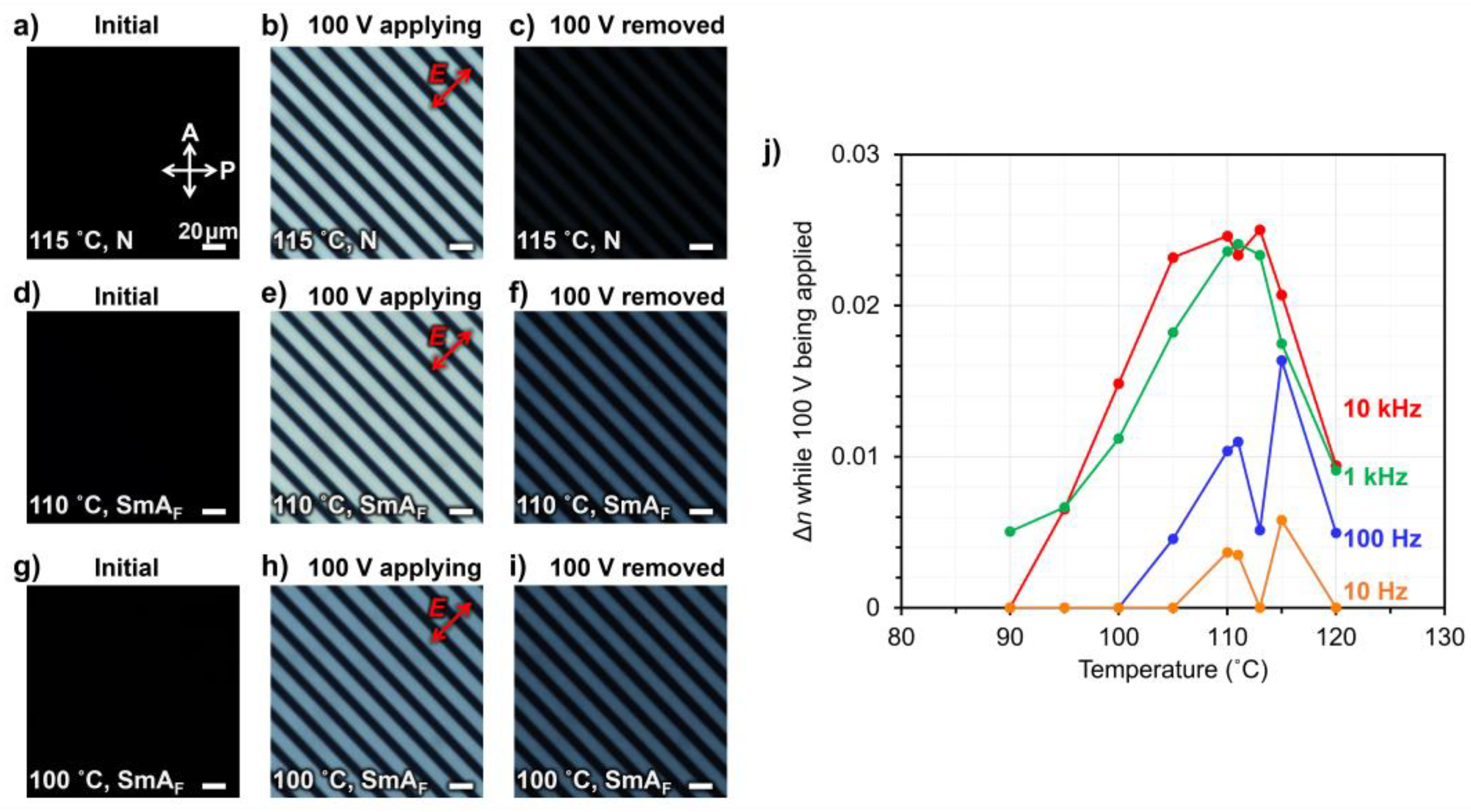
Figure 4A,
Figure 4D and
Figure 4G, before the application of the
E-field, the PDLC sample does not show Δ
n and does not transmit light in the polarizing optical microscopy (POM) observation under crossed nicols. When a voltage of 100 V was applied at a frequency of 10 kHz, Δ
napp. was induced by the
E-field because light was transmitted between the electrodes (
Figure 4B,
Figure 4E, and
Figure 4H). The same procedure was also used to measure Δ
napp. at frequencies of 1 kHz, 100 Hz, and 10 Hz, at various temperatures, when 100 V was applied. A comparison of Δ
napp. during the application of 100 V at various frequencies indicates that larger Δ
napp. values were observed at higher frequencies. This is contrary to the trend of
ε’, wherein larger
ε’ values were observed at lower frequencies. This result suggests that when 100 V is applied to the PDLC, a sufficient voltage is not applied to the EST-rich domain to reorient the EST molecules unless it is in the high-frequency range of approximately 1 kHz or higher. If larger phase-separated structures were obtained, the PDLC would exhibit higher light scattering; however, a larger Δ
napp. would be induced. Δ
napp. was almost zero during the application of 100 V in the case of a transparent PDLC with an SmA LC, 4-cyano-4’-
n-octyloxybiphenyl (8OCB). This also confirms that this PDLC using EST is more EO-responsive compared to other SmA LC-based materials. After the removal of the
E-field, Δ
nrem. decreased significantly as only a small amount of light is transmitted between the electrodes at 115 °C (
Figure 4C). Meanwhile, at 110 and 100 ˚C, the light intensity transmitted between the electrodes was higher (brighter), indicating the retention of larger Δ
nrem values (
Figure 4F and
Figure 4I). The retention of Δ
nrem. after the removal of the
E-field indicates that the EST molecules did not completely relax to their initial (random) molecular orientation after the removal of the
E-field and that the molecular orientation induced by the
E-field was partially maintained. Δ
nrem. was completely erased upon heating the sample above 130 ˚C.
The relationship between the Δ
n memory properties and temperatures after the removal of the
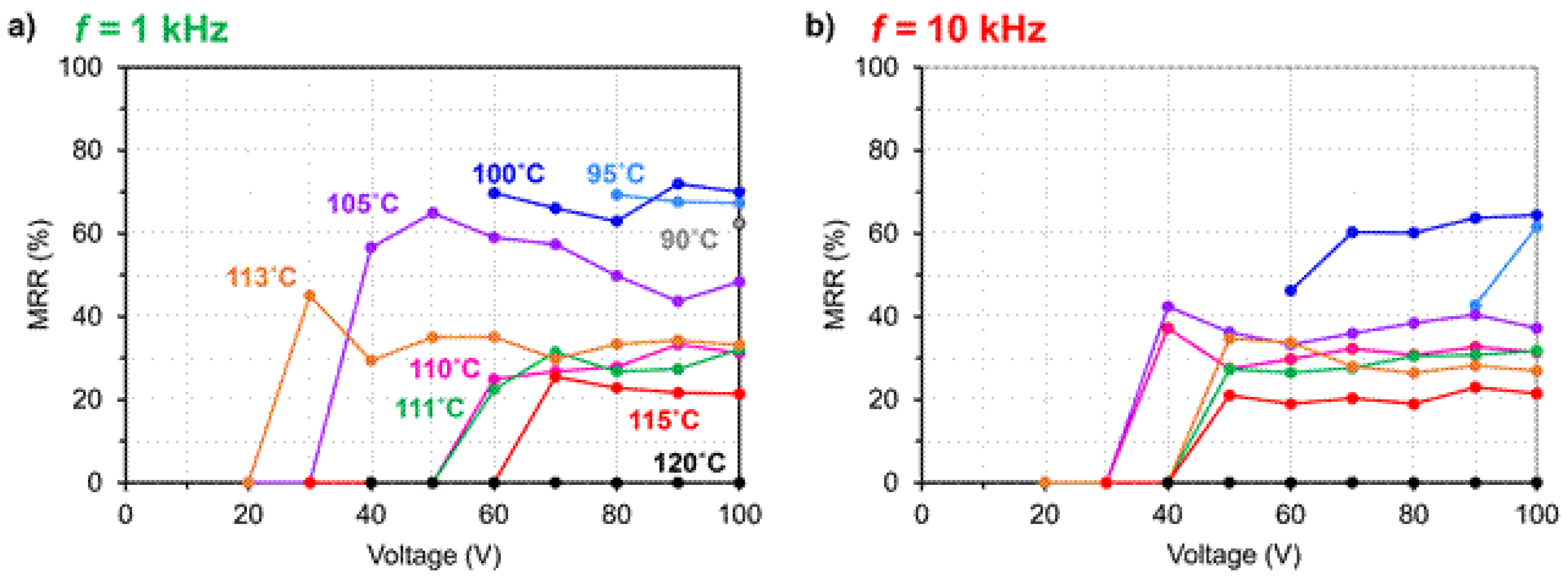
E-field was meticulously investigated for the frequencies of 1 kHz and 10 kHz, where the better electro-birefringence effects were observed. The proportion of Δ
n memorized after the removal of the
E-field was defined as the memory retention rate, MRR, which is calculated as follows:
As regards the temperature dependence of MRR, it is less than 40% above 111 °C, indicating that EST is considered to be the N phase in the PDLC sample. However, below 100 °C, where the EST is considered to have completely transitioned to SmA
F, the MRR is more than 60%. These features were similar at the frequencies of 1 and 10 kHz (
Figure 5). As evident from the DSC curve in
Figure 3A, the phase transition from N to SmA
F proceeds within broad temperature ranges; the MRR was not likely to be high given the presence of both SmA
F phase and N phase at 110 °C. At higher temperatures, the MRR is less than 40% because of the relaxation of the molecular orientation of the EST to the initial orientation upon the removal of the
E-field. In contrast, in the temperature range of the SmA
F phase, the elastic modulus of EST was relatively higher than that of the N phase, and the relaxation of the molecular orientation after the removal of the
E-field was apparently suppressed. In addition, when a triangular-waveform
E-field was applied to the material, currents due to polarization reversal were observed, confirming its ferroelectricity (
Figure S2 in the Supporting Information).
Previously, we fabricated N LC-based nano-PDLCs with phase-separated structure sizes of 100–200 nm, with an MRR of at most 50% [
17]. The material in this study used the polar monofunctional vinyl monomer NVP, which was thought to provide a polar anchoring force between the polymer interface and the EST molecules. The anchoring effect was expected to be stronger in the nano-PDLC in this study than in the previous study because of the lower LC constitutive fraction and smaller phase-separated structure; further, the previous work did not use NVP as the monomer. Because anchoring at the interface with the polymer is the driving source of LC reorientation after the removal of the
E-field, a strong anchoring effect is disadvantageous for the memory effect. The high MRR (70%) in this study, despite stronger anchoring than in previous studies, indicates that the ability of SmA
F LC to retain molecular orientation after
E-field removal is beneficial. Because the LC domains within the nano-PDLCs are remarkably fine, the LC confined within them are subjected to large deformations. In the memory state of nano-PDLCs, slight deformations of the Sm layers and presence of minor defects may be acceptable; conversely, large layer deformations and presence of numerous defects would lead to memory degradation [
20]. The loss of approximately 30% of the Δ
n memory is apparently due to the complex polymer structure and anchoring forces that distort the molecular orientation of EST near the polymer interface. This results in the inability to maintain a Sm layered structure near the polymer, as well as a partial N-like orientation ordering and enhanced relaxation. The anchoring of polymers with large polarities may be effective in maintaining the molecular orientation by retaining the ferroelectric polarization of EST molecules. This PDLC fabricated in this study can be driven at voltages lower than the driving voltages of conventional SmA LC-based materials. It can also be pinned at any Δ
n value more efficiently than N LC-based materials, making it suitable for applications such as display elements without viewing angle dependence and electrically tunable micro lenses.


