1. Introduction
Plant cultivation in special physical circumstances, especially in different magnetic and gravitational conditions, is a relatively new research trend related to the development of space technologies. It is necessary, however, since plants are known to be influenced by gravitropism, resulting in roots growing downwards, while shoots grow upwards, led not only by light, but also by gravity [
1,
2,
3].
Such research can be carried out in two different ways. The first one relies on sending samples into space [
4] and placing them on board of the International Space Station (ISS) [
5,
6,
7]. This approach is relatively expensive and limited by the capabilities of today’s space technology. The second method is to arrange experiment in conditions similar to those met in space. A common approach to simulate plant growth in space is given by a clinostat which constantly changes the plant orientation, so that on the average all directions are indistinguishable [
8,
9]. Typically, rotational speeds of around 1 rpm are used for plant experiments [
10], while too slow rotation may lead to helical plant growth [
11].
Comparison of experiments in a clinostat and in real microgravity often show similar results, as long as suitable rotational speeds are chosen [
12,
13]. Nevertheless, another important impact on plant growth, besides gravity, is often disregarded, that is the Earth magnetic field with its induction of the order of 45 μT = 0.045 mT. Magnetic fields with a broad range of magnitudes have been investigated with respect to their impact on plant growth. Static and alternating magnetic fields of 400 mT and 30 mT, respectively, were shown to positively impact seed germination and chlorophyll content of soybean seeds, respectively [
14]. Static magnetic fields between 420 mT and 580 mT were also found to increase root growth of
Arabidopsis thaliana [
15]. By applying a static magnetic field of 110 mT, the growth of
Pelargonium graveolens could be improved regarding plant height, root length, chlorophyll content, and other parameters [
16]. While such relatively large magnetic fields are mostly regarded as positive for plant, only few experiments were found on the influence of switching off the Earth magnetic field, and those showed often inconsistent or irreproducible results [
17,
18,
19,
20], underlining the importance to further investigate plant growth in zero magnetic field for future space missions. Shielding the Earth magnetic field is possible with a Helmholtz cage [
21], as it is described in the next section.
Here we report the construction, electrical configuration and software for system consisting of a two-axial two-frame clinostat and a Helmholtz cage large enough to be coupled with the clinostat. We also show preliminary bio-inspired results of experiments in clinostat with beans as an example of simple edible plants.
2. Design and Construction
2.1. Principle of Clinostat Operation
The two-axis clinostat developed in the recent project, also called random positioning machine [
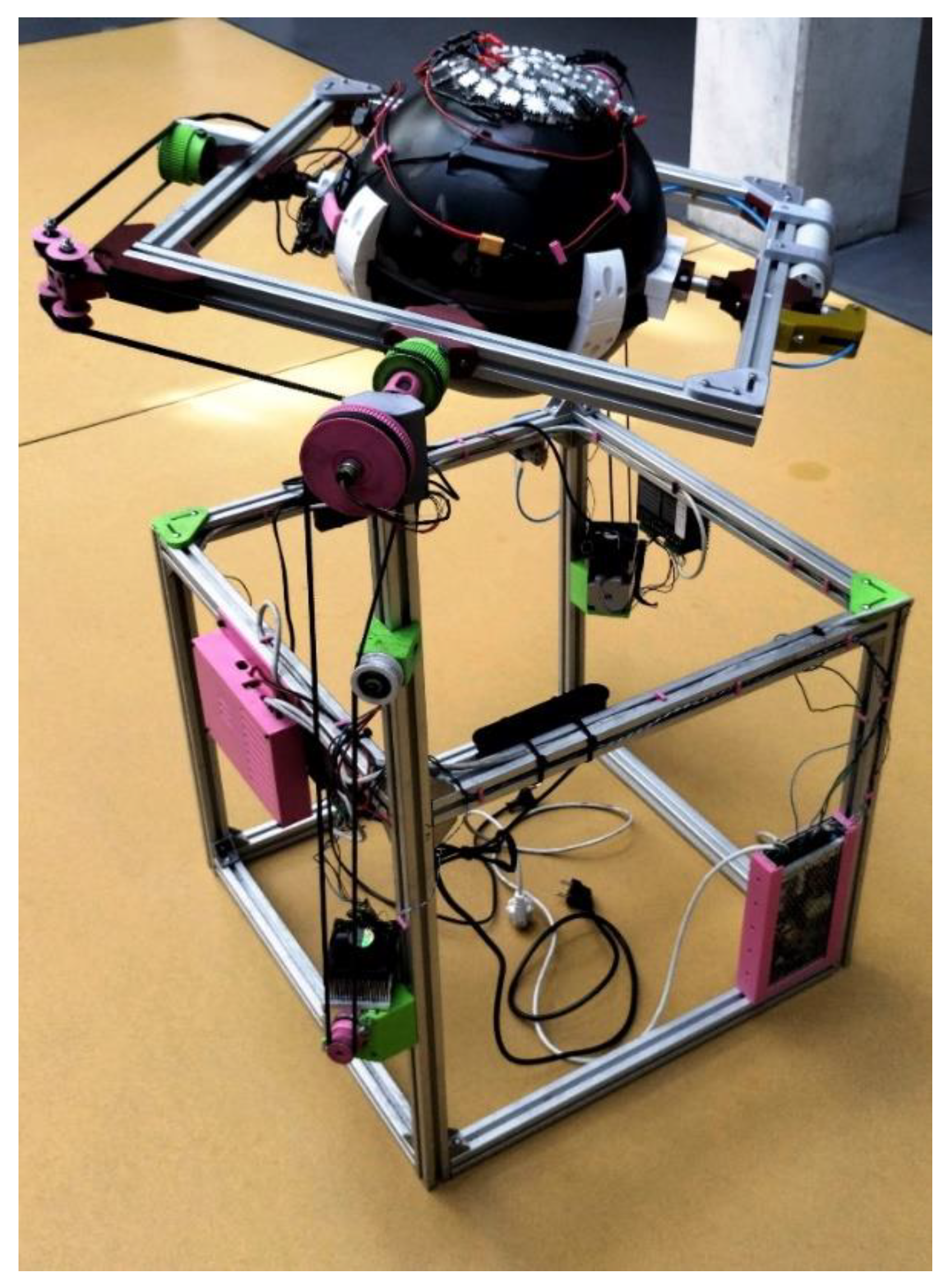
22], consists of an aluminum frame (
Figure 1) which rotates relative to the clinostat base that is also made of aluminum. Inside the rotating frame, a spherical region rotates independently, where experiments in simulated microgravity can be carried out. In the sphere, several physical parameters, such as acceleration, angular velocity, temperature, humidity, and light intensity can be measured and sent remotely to an external computer. Moreover, the cultivation area can be observed by a camera providing on-line visual information about the growth progress.
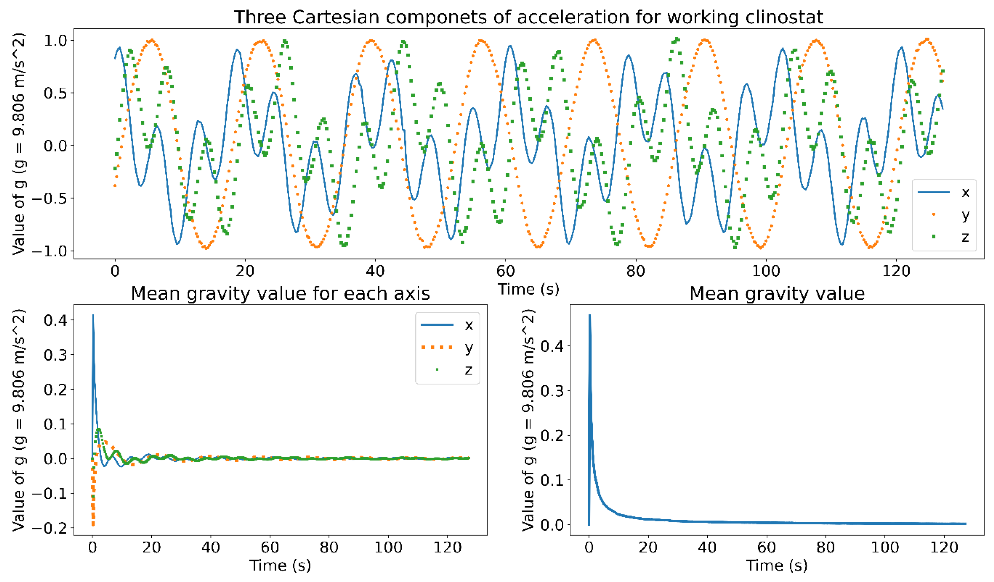
The two rotations, one of the frame and one of the cultivation sphere, create a situation in which the average effective value of gravity is reduced to zero. Because of that, plants are not able to sense gravity direction and are thus enforced to grow in a state similar to weightlessness in cosmic space. The ratio of angular velocities, of the frame and the sphere, define the number of turnovers for which the optimum conditions of average zero-gravity will be achieved. Our calculations and tests showed that the ratio of 1:2.2 (frame to sphere velocities) gave also the lowest mean gravity fluctuations, leading to values between 0.0657 g and 0.0072 g. Since the axes operate at constant speeds, the devices belongs to 3D clinostat class.
Figure 2 depicts the results of time-dependent measurements of the acceleration components using built-in accelerometers. Additionally, which is worth noting, the angular velocities have to be kept at low values to get satisfactory conditions for plant growth, especially if to take into account the spatial distribution of humidity in cultivation area [
23]. Thus, we usually used a velocity of 0.31 rad/s for the frame and 0.68 rad/s for the sphere.
2.2. Mechanical Components of the Clinostat
In the construction process, we applied strictly the postulate to limit ferromagnetic material as much as possible. Timing gears, pulleys, construction connectors for the clinostat frames, and the other cultivation parts are made of poly(lactic acid) (PLA) or polyethylene terephthalate glycol (PETG) filaments using 3D printing technology. The cultivation sphere is made from polyester and its parts are connected with screws and bolts made of nylon.
The mechanical part of the clinostat consists of the static mechanical housing and the cultivation area. The frames are made of typical V-SLOT type aluminum profiles. The cultivation chamber was adopted from a commercially available geographical globe. The rotating alumina frame is driven by two-timing gears and one belt (cf.
Figure 1 – the motor mounted at the back vertical edge). To pass rotation from the second stepper motor to the sphere, a two-timing belt mechanism was used. The rotating frame axle is mechanically independent from the sphere axle, whereby it can rotate at its own speed and can change orientation. The gearbox is kinked at a right angle and the belt is guided with idler pulleys to power sphere rotations. Each timing belt has its independent tensioning mechanism. The axles are made of aluminum pipes in which water pipes and electrical cables are embedded. The water supply system is made of a peristaltic pump (DP-DIY type, 12 VDC, efficiency of 5-10 mL/min, made by INTLLAB®), Polyurethane tubes of internal diameter equal to 2 mm, rotational connectors, and perforated silicon tubes located close to the cultivation area. A peristaltic pump prevents reverse water flow. To reduce angular velocity fluctuations, resulting from uneven weight distribution, additional counterweights were used, for example, to balance the LED lighting system.
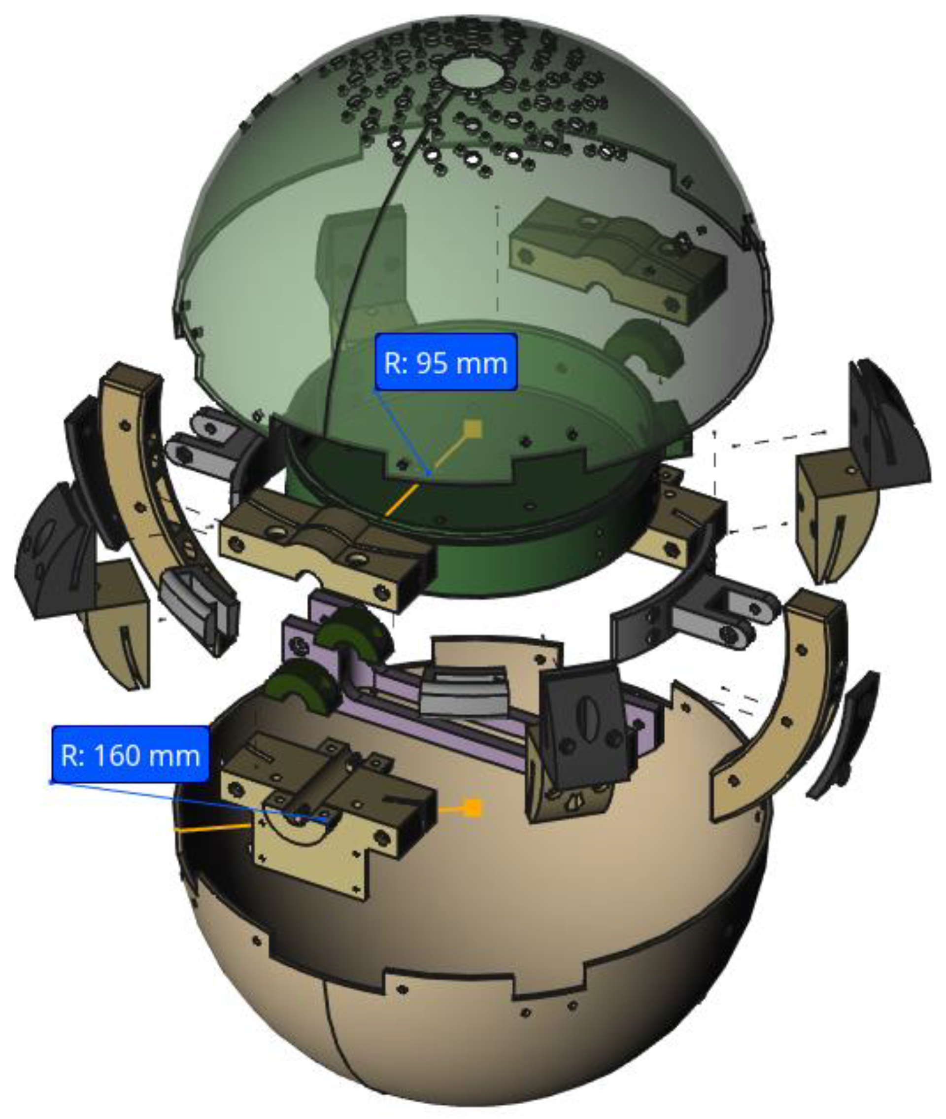
The cultivation process has to be protected from external light sources to keep it controlled. The sphere has a diameter of 320 mm (
Figure 3) and is divided into two semi-spheres to allow access and enable preparation of seeds, cleaning, and harvesting. Inside the sphere, there is a plastic cylindrical basket with radius of 95 mm, located symmetrically at the main cross-section, which is the base for cultivation. Directly attached to the plastic sphere, a second (apart from the main computer mounted to the main frame – cf.
Figure 1), small single-board computer of the Raspberry Pi type is used to acquire data from sensors. The clinostat stepper motors (Nema 24 manufactured by Nanotec®) have 4 Nm torque. Each motor is driven by a DM556 stepper motor driver manufactured by Leadshine®. The total size of the clinostat fits a volume of 620 mm width and length, respectively, and 963 mm height.
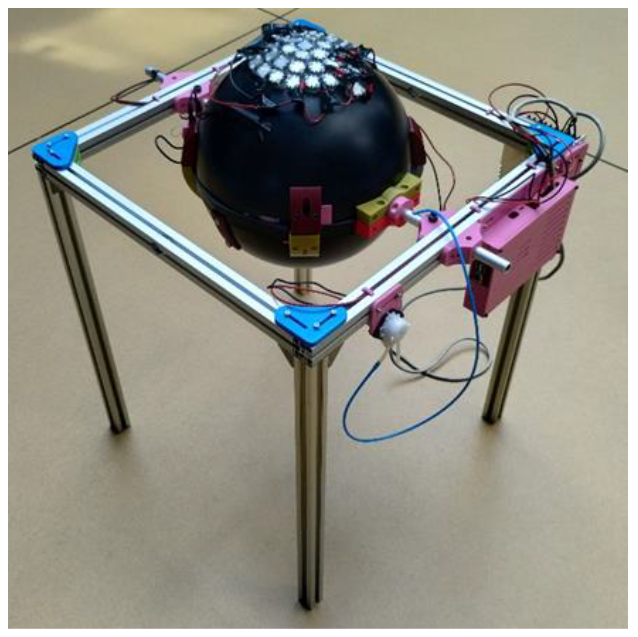
In addition to the clinostat, a static copy – the reference device – was constructed. It is used to compare results from zero mean gravity experiment to normal Earth gravity circumstances.
Figure 4 shows the static version.
2.3. Electrics and Sensors of the Clinostat
Electric power is provided to the microcomputer and LEDs with cables that are run inside aluminum profiles and axles. Due to rotations of the construction elements, special slip rings with up to 12 connectors were used (KYM12B type made by Asiantool®).
In the cultivation area, diverse sensors are applied to monitor the experiment. Two temperature sensors MCP9808 (Adafruit®) at opposite positions measure the temperature. Light intensity sensors APDS9960 (Adafruit®) are placed on basket guides. The soil moisture sensor is made of two aluminum rods mounted parallelly and distanced with plastic spacers. The 3-axis LIS3DH (Adafruit®) acceleration sensor is mounted in the center of the sphere to monitor the microgravity state. Additionally, two cameras are added to take pictures of cultivated plants.
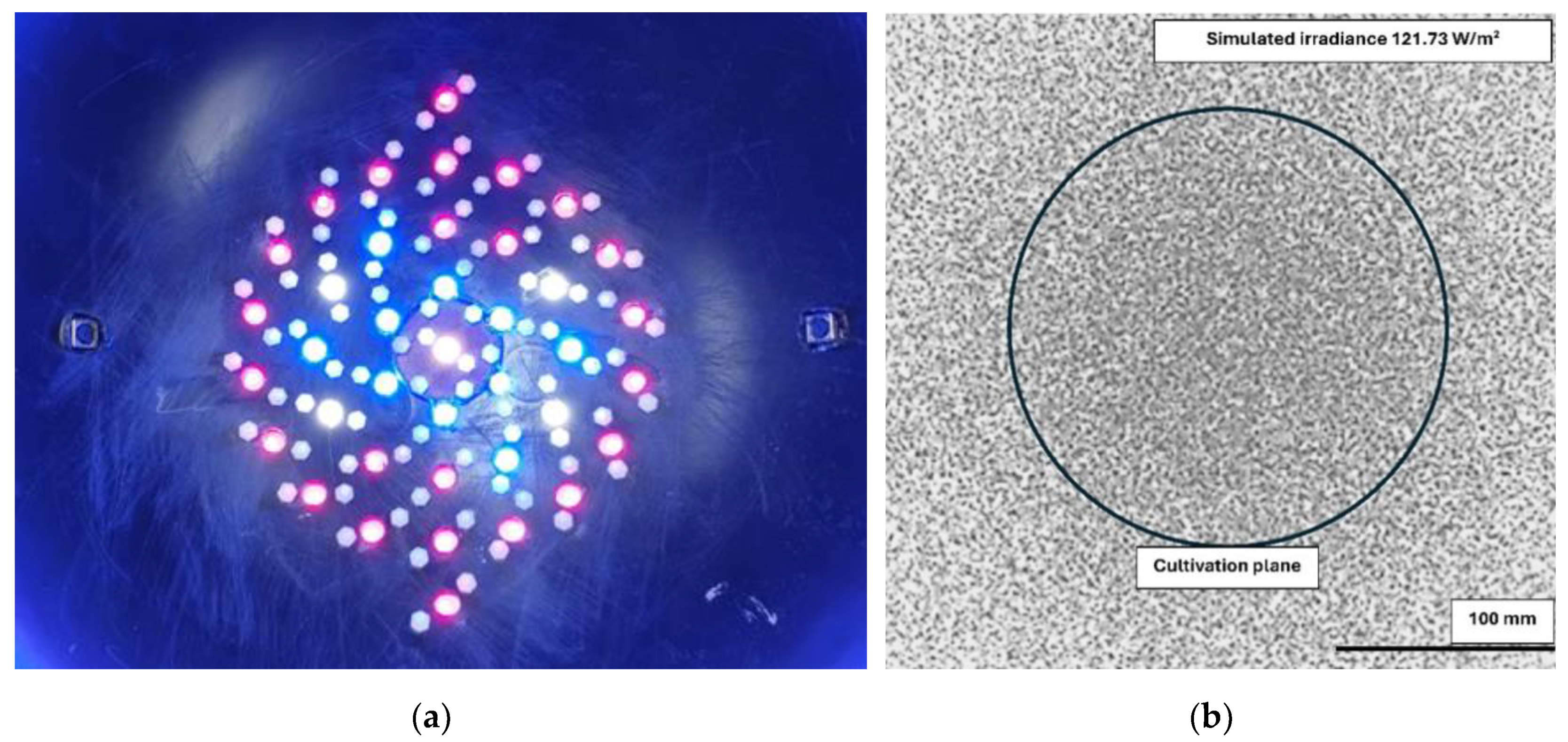
The LED illuminator, shown in
Figure 5a, consists of 24 red (PK2N-3LME-HSD, 650-670 nm, 3 W), 10 blue (PM2E-3LBS-SD, 455-475 nm, 3 W), and 5 white diodes (PM2E-3LVS-R7, 3 W), manufactured by ProLight Opto®. Each one has a maximum power of 3 W. The total mass of diodes with radiators equals 273 g. The number of diodes and colors was chosen in such a way to mimic the spectrum supporting photosynthesis of plants [
24]. Light intensity is controlled with a 12 V pulse width modulation (PWM) signal. Each diode has its radiator to remove heat. Diodes are mounted on the upper half of the sphere and point toward the basket. The position of diodes was examined by Monte Carlo simulations to find the illumination area uniform (
Figure 5b).
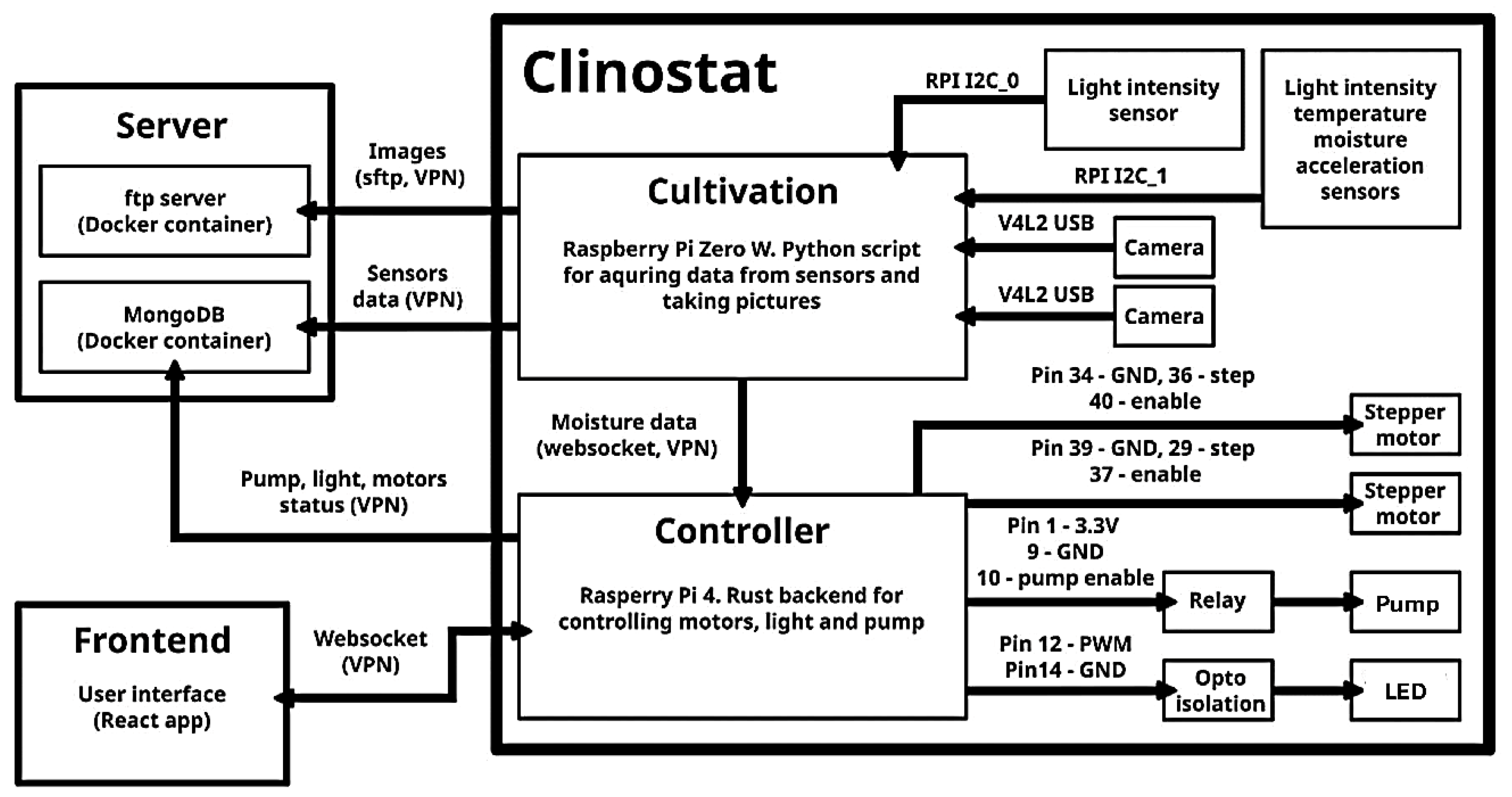
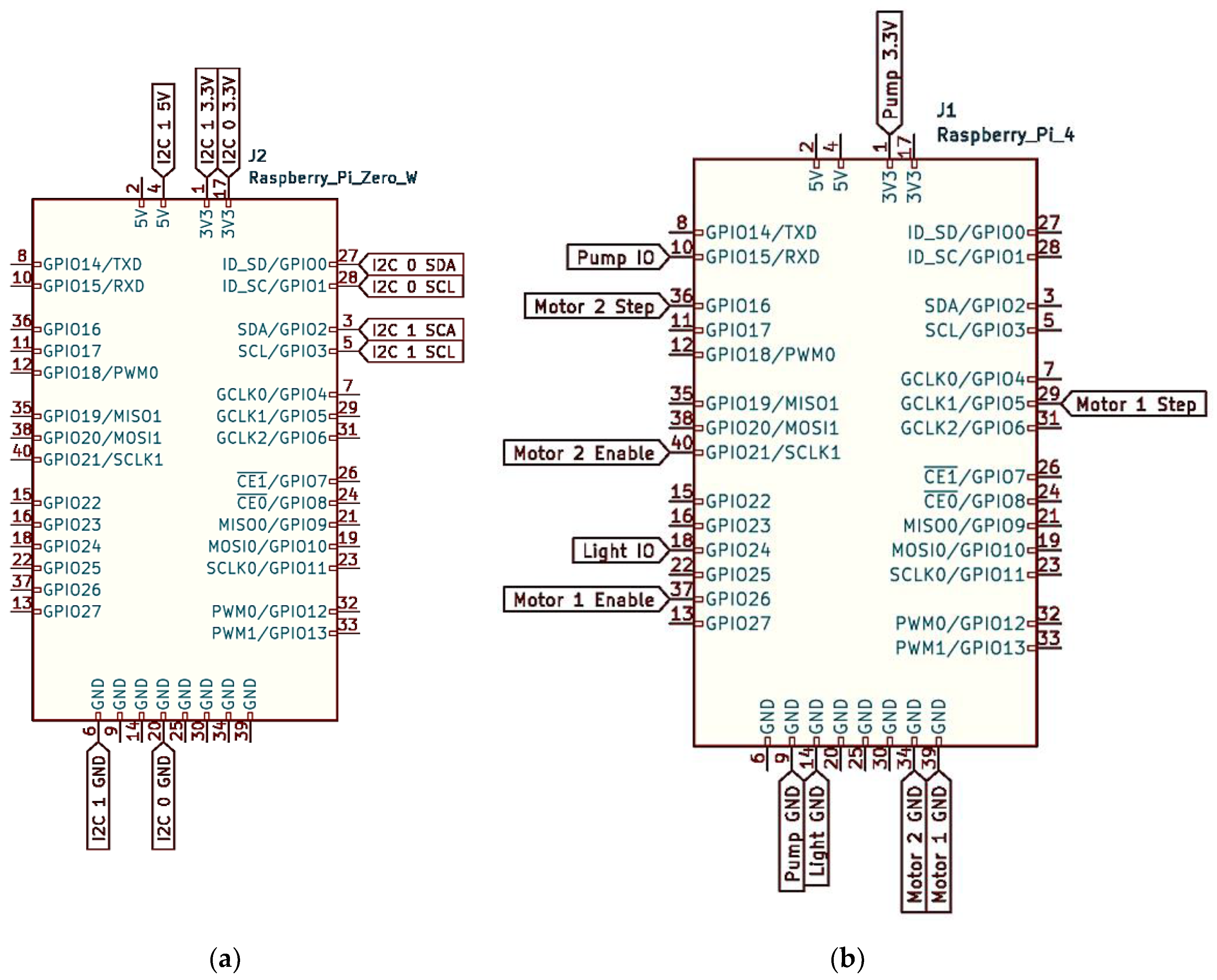
The main clinostat computer (Raspberry RPi4) controls motors, light intensity of diodes, and water pump flow. The second computer (Raspberry Pi Zero W) was mounted on the sphere to collect signals from sensors and cameras. The general view of clinostat signals flow is given in
Figure 6. Details about computers (Cultivation, Controller) signals are seen in
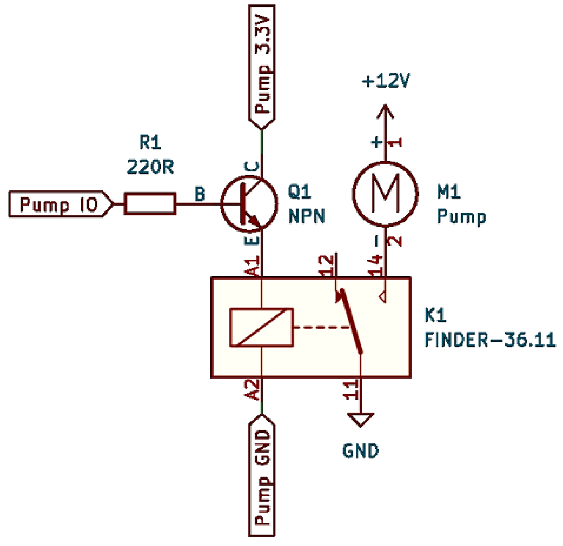
Figure 7. Details about the relay block and the opto-isolation block are explained in
Figure 8, and
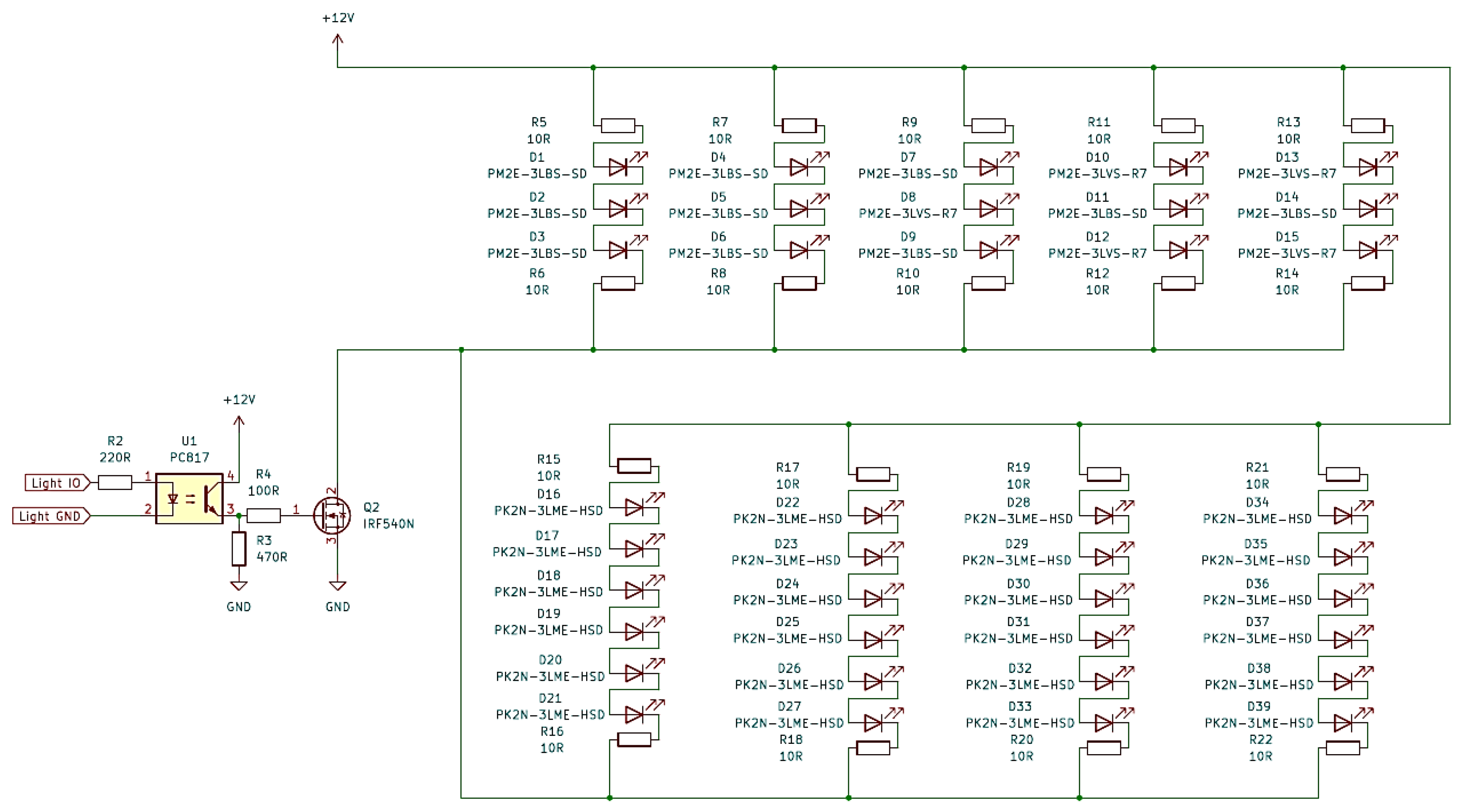
Figure 9, respectively. The control of a pump by the RPi4 computer met some electric incompatibility. The current that can be taken from the RPi4 IO pins is too low to power devices, so a solution with BC547 transistor was applied to pass enough amount of energy. Similarly, the lighting control circuit uses the IRF540N MOSFET to control the LED’s lighting system
2.4. Clinostat Software
A part of software, associated with the image processing of cultivation area, is written in Python on the base of a so called microservice conception that is commonly used in network applications. Each component is treated as an elementary networked service that can be connected to a hardware device or to another software part. Each service sends data or responds to requests from other services. The WebSocket protocol is used in this way to communicate between all the parts (cf.
Figure 6).
Image acquisition is realized by Python script that utilizes sftp protocol, while the captured images are processed with the Open CV library. They are saved to the file system and sent remotely to the external sftp server to release local memory. Hence, the file names are sent to the external MongoDB [
25] database as HTTP strings, so everyone connected via the VPN service to the system computer can open each image in a browser.
The main clinostat software controls motors, light, and pumps. It is written in Rust Programming Language [
26] using so called Tokio library [
27]. Tokio is an asynchronous input/output framework for Rust, and it is used for network communication between parts with the use of WebSockets protocols.
The user interfaces for the clinostat and the cage were realized using the React framework [
28] and the Electron framework [
29], respectively. The choice of such tools was arbitrary, and the only reason was to test these and familiarize with them. The frameworks utilize component ideology – each element of the web page can be symbolized as a programmable block, which has its functionalities and can share its properties. The component can be independently refreshed, so if new data come from the system, information will be updated at the frontend, i.e. the user interface layer. The clinostat frontend enables controlling light intensity, moisture, and angular velocities, while the cage frontend controls electric parameters.
2.5. The Helmholtz Cage
The constructed Helmholtz cage is a device that can modify the magnetic field inside its central part where the clinostat can be located. The cage is built from three pairs of octagonal coils with the biggest one inscribed in a circle of diameter 2 m – the other two pairs of coils are slightly smaller to be mounted inside the largest coils. 90 turns per coil were wound on alumina skeletons using 1.2 mm diameter copper wire. The octagonal coil shape was chosen because of its induction properties being very close to those of a circle, while the mechanical construction is simple enough. It is worth mentioning that in the simplest case, square cages are commonly used [
30,
31,
32], but they have limited magnetic field homogeneity.
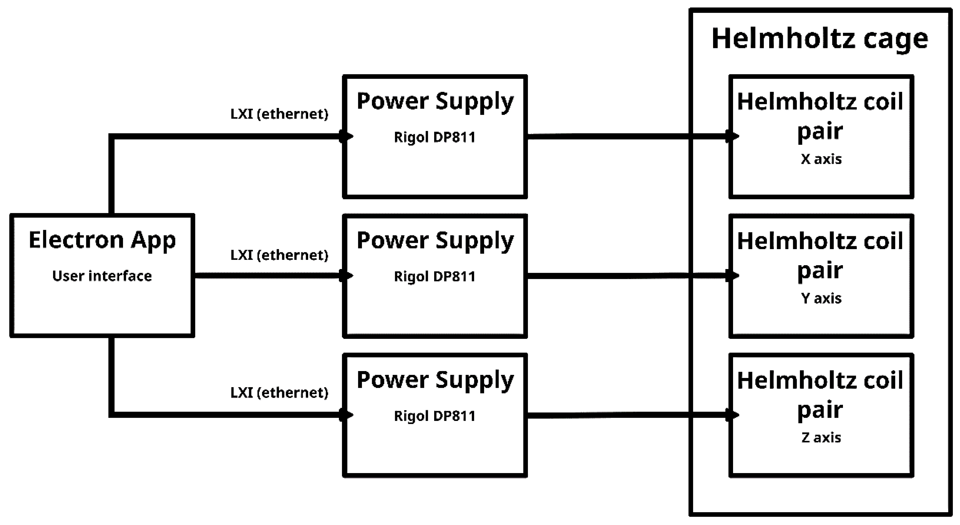
The cage is powered with three Rigol® DP811 variable power supplies (
Figure 10). Each supply powers one Helmholtz coil pair. The maximum power that can be delivered to one pair of coils equals 100 W (20 V, 5 A).
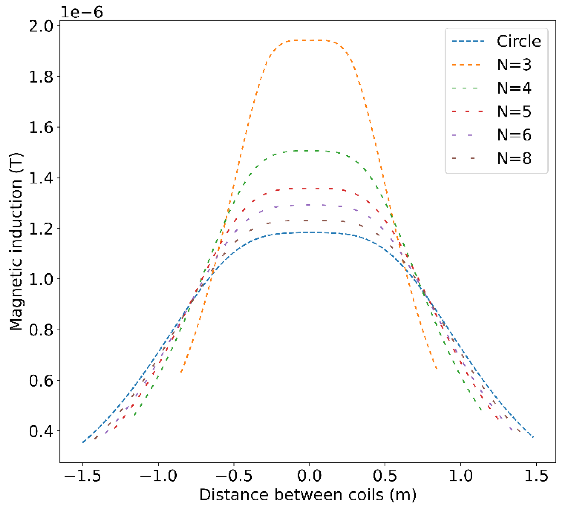
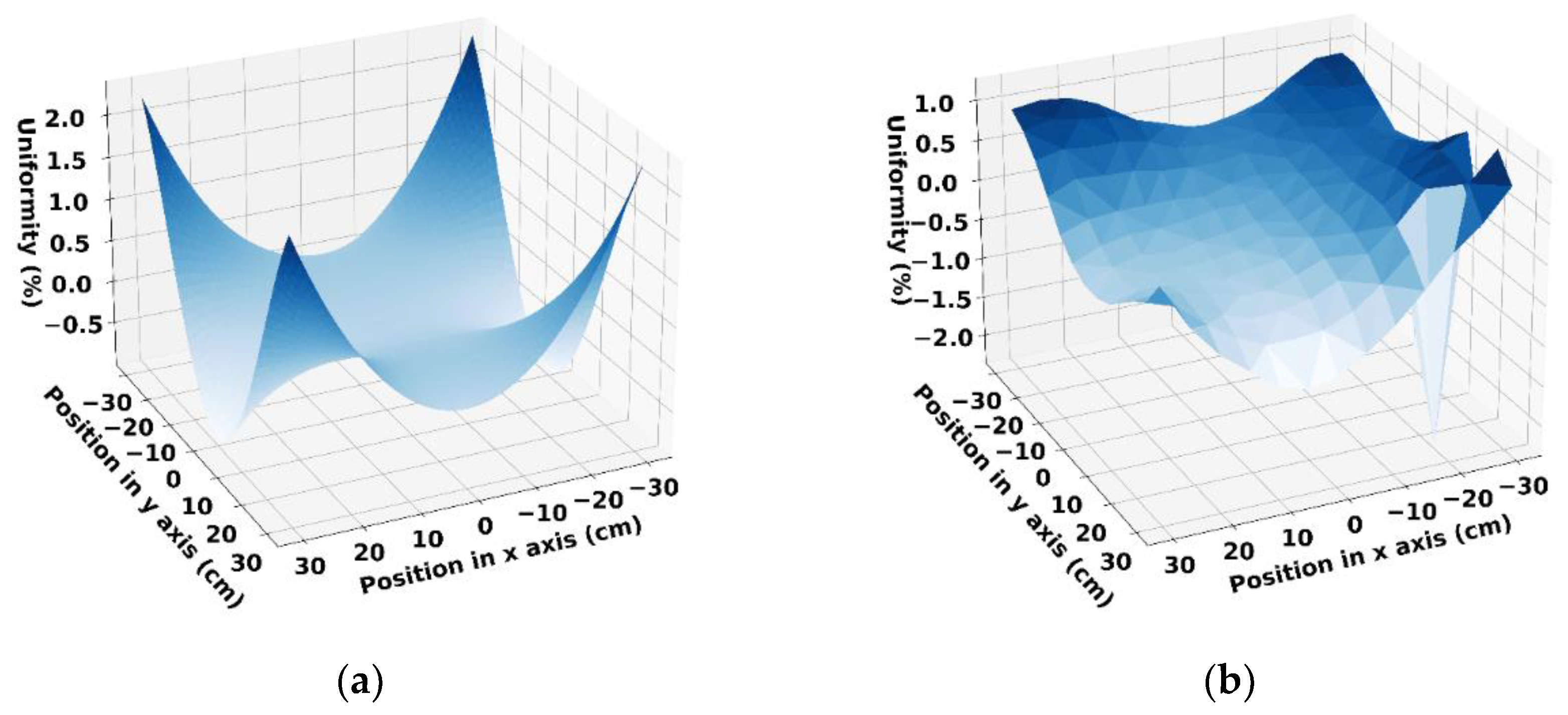
To find the magnetic field spatial distribution inside the cage, adequate calculations, on the base of Ampere’s law using a custom-made Python code, were performed. The imposed condition of about 1% deviation from the field value in the cage center (located 1 m above the construction base) resulted in determination of the optimum experimental region of homogeneity. In
Figure 11 and
Figure 12, the results of simulations are presented for different numbers
N of hypothetical coil polygon sides (we used
N=8). The simulation was further validated with measurements inside the built Helmholtz cage.
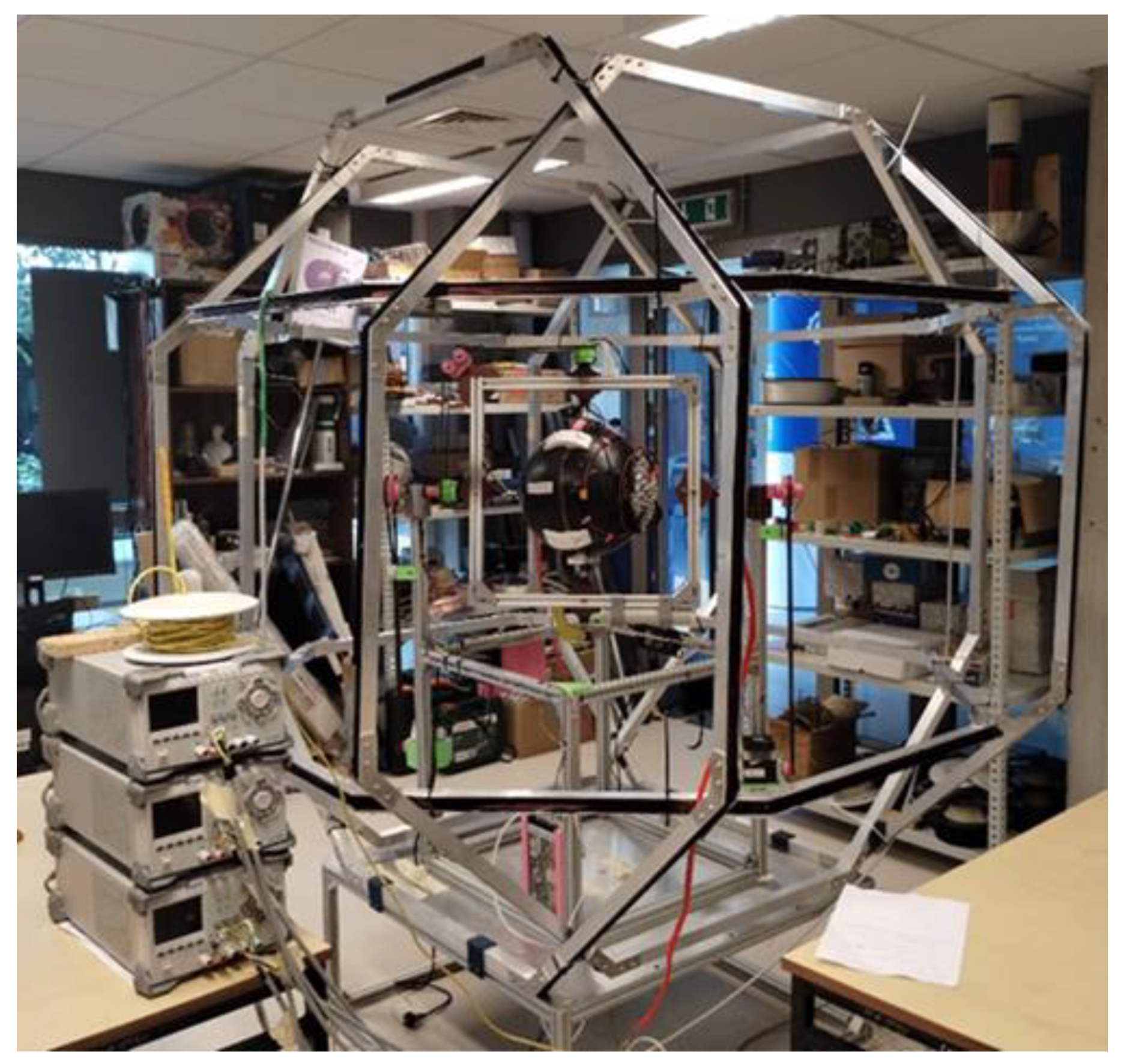
As mentioned earlier, the clinostat and the Helmholtz cage were designed complementary, in the sense that they are dimensionally compatible (
Figure 13) – the center point of the cultivation sphere is identical to the middle of the cage. Importantly, the diameter of the sphere is comparable with the previously simulated region (0.4 m x 0.4 m x 0.4 m) possessing adequate field homogeneity.
2.6. Cultivation Experiments
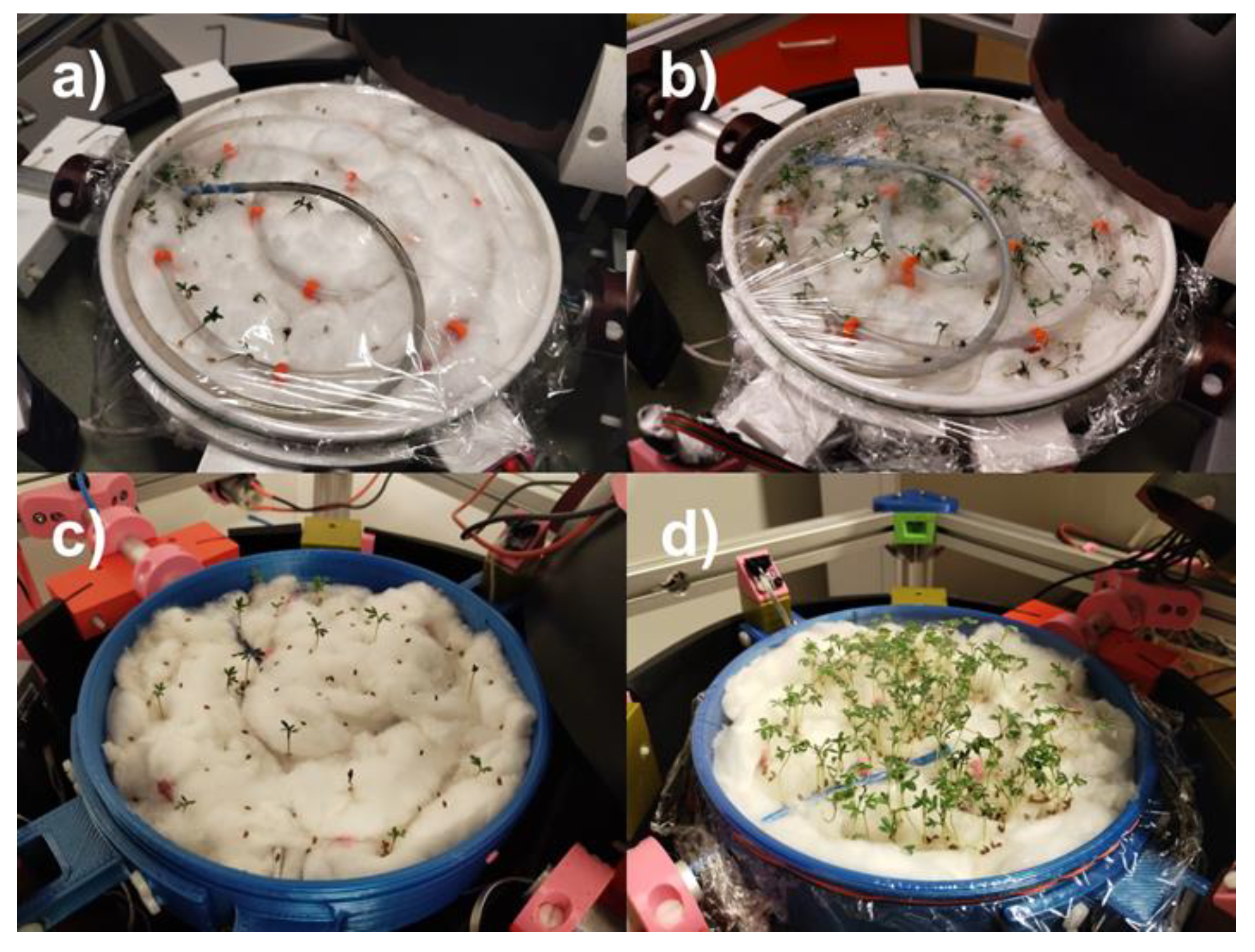
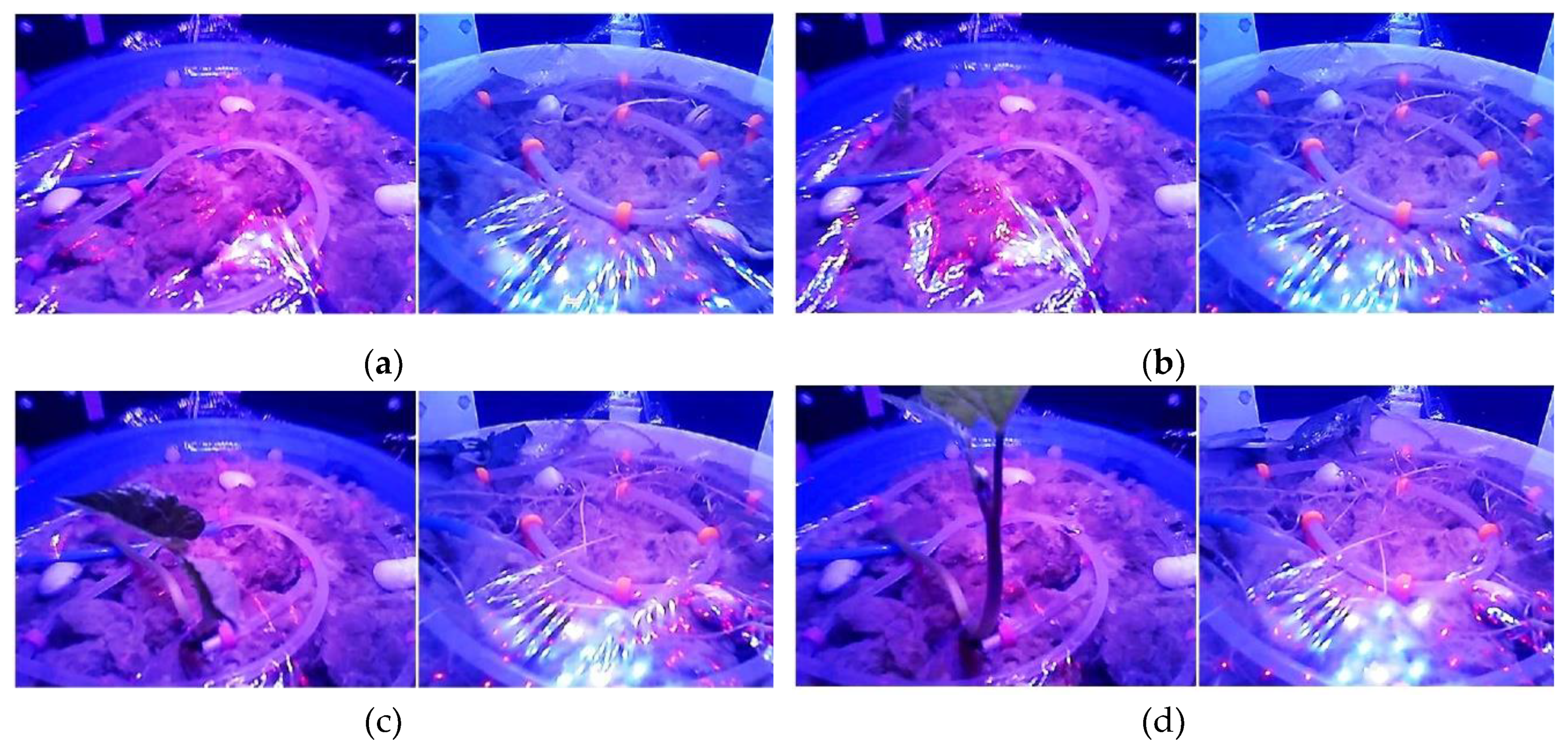
To investigate the clinostat’s effect on plant growth, we performed several preliminary cultivations (
Figure 14 and
Figure 15). We used
Lepidium sativum L. (
Figure 14) and
Phaseolus coccineus L. (
Figure 15) as test plants because they are easy to grow and have a short vegetation period. The figures present the two one-week growth results in the clinostat and in the reference static sphere. Videos of the cultivation process of
Phaseolus coccineus L. can be found as supplementary information or on request from authors. Gravitropism is highly visible in all plant’s parts: stems, roots, and leaves. Cotton was used as the substrate material because of its good water retention capabilities. In the first experiments to block the movement of the breeding, a properly perforated foil with holes was used. This is not the only solution. It is also possible to use the appropriate mesh made of plastic material. The results have preliminary character, and future experiments in a variety of circumstances will be conducted, especially with the inclusion of magnetic field variation.
3. Conclusions
In the manuscript, a clinostat with a surrounding Helmholtz cage were presented. The system enables plant growth under simulated microgravity with the Earth magnetic field cancelled out or modified, respectively. Due to the impact of both factors on plant growth, simulations of plant cultivation in space can be performed with very conveniently, without organizing special orbital missions. First experiments with Lepidium sativum and Phaseolus coccineus showed a significant difference between plants grown in simulated microgravity, i.e. in the clinostat, and under static conditions, i.e. in the usual Earth gravitational field. Future experiments will also be conducted in the absence of a magnetic field to show its impact on the dynamics of the growth of biological structures. Further research will also be conducted with microscopic objects, such as, for example, bacterial colonies. The authors hope that the information presented will also be useful for scientists who want to build their own similar experimental system.
Author Contributions
Conceptualization, T.B. and A.E.; methodology, T.B.; software, M.M.; validation, T.B.; formal analysis, M.M. and T.B.; investigation, M.M.; resources, T.B.; writing—original draft preparation, T.B. and A.E.; writing—review and editing, all authors; visualization, M.M. and T.B; supervision, T.B.; funding acquisition, T.B. All authors have read and agreed to the published version of the manuscript.
Funding
The process of designing and building was supported by the student research clubs GOLF and SAT at the Institute of Physics – Center for Science and Education, Silesian University of Technology in recent years. Further development of the system and the recent results were made possible thank to the BKM-747/RIF2/2024 (14/020/BKM24/0051) grant obtained from Silesian University of Technology Program received by the first author (M.M.).
Institutional Review Board Statement
Not applicable.
Informed Consent Statement
Not applicable.
Data Availability Statement
The original contributions presented in the study are included in the article, further inquiries can be directed to the corresponding author.
Conflicts of Interest
The authors declare no conflicts of interest. The funders had no role in the design of the study; in the collection, analyses, or interpretation of data; in the writing of the manuscript; or in the decision to publish the results.
References
- Chen, R. J.; Rosen, E.; Masson, P. H. Gravitropism in higher plants. Plant Physiology 1999, 120, 343–350. [Google Scholar] [CrossRef] [PubMed]
- Mancuso, S.; Shabala, S. Rhythm in plants: Phenomenology, mechanisms, and adaptive significance. Springer, Berlin Heidelberg New York, 2007.
- Blachowicz, T.; Ehrmann, A.; Malczyk, M.; Stasiak, A.; Osadnik, R.; Paluch, R.; Koruszowic, M.; Pawlyta, J.; Lis, K.; Lehrich, K. Plant growth in microgravity and defined magnetic field. Proc. of International Conference on Electrical, Computer, Communications and Mechatronics Engineering (ICECCME), 1-8 (2021).
- Driss-Ecole, D.; Legué, V.; Carnero-Diaz, E.; Perbal, G. Gravisensitivity and automorphogenesis of lentil seedling roots grown on board the International Space Station. Physiol Plant. 2008, 134, 191–201. [Google Scholar] [CrossRef] [PubMed]
- https://ntrs.nasa.gov/api/citations/20160005059/downloads/20160005059.pdf (accessed 29-06-2024).
- https://www.nasa.gov/wp-content/uploads/2019/04/veggie_fact_sheet_508.pdf (accessed 29-06-2024).
- Zabel, P.; Bamsey, M.; Schubert, D.; Tajmar, M. Review and analysis of over 40 years of space plan growth systems. Life Sci. Space Res. 2016, 10, 1–16. [Google Scholar] [CrossRef] [PubMed]
- Hoson, T.; Kamisaka, S.; Buchen, B.; Sievers, A.; Yamashita, M.; Masuda, Y. Possible use of a 3-D clinostat to analyze plant growth processes under microgravity conditions. Adv. Space Res. 1996, 17(6-7), 47-53.
- Theoret, N. Honors Theses. 2783, Western Michigan University, Kalamazoo, 2016.
- Boucheron-Dubuisson, E.; Manzano, A. I.; Le Disquet, I.; Matía, I.; Sáez-Vasquez, J.; van Loon, J. J. W. A.; et al. Functional alterations of root meristematic cells of Arabidopsis thaliana induced by a simulated microgravity environment. Journal of Plant Physiology 2016, 207, 30–41. [Google Scholar] [CrossRef] [PubMed]
- Sievers, A.; Hejnowicz, Z. How well does the clinostat mimic the effect of microgravity on plant cells and organs? ASGSB Bulletin 1992, 5, 69–75. [Google Scholar] [PubMed]
- Lorenzi, G.; Perbal, G. Root growth and statocyte polarity in lentil seedling roots grown in microgravity or on slowly rotating clinostat. Physiologia Plantarum 1990, 78, 532–537. [Google Scholar] [CrossRef]
- White, J. Formation of red wood in conifers. Proc. Royal Society Victoria 1908, 20, 107–124. [Google Scholar]
- Michalak, I.; Lewandowska, S.; Niemczyk, K.; Detyna, J.; Bujak, H.; Arik, P.; et al. Germination of soybean seeds exposed to the static/alternating magnetic field and algal extract. Engineering in Life Sciences 2019, 19, 986–999. [Google Scholar] [CrossRef] [PubMed]
- Jin, Y.; Guo, W.; Hu, X. P.; Liu, M. M.; Xu, X.; Hu, F. H.; et al. Static magnetic field regulates Arabidopsis root growth via auxin signaling. Sci. Rep. 2019, 9, 14384. [Google Scholar] [CrossRef] [PubMed]
- Nyakane, N. E.; Sedibe, M. M.; Markus, E. Growth response of rose geranium (Pelargonium graveolens L.) to calcium:magnesium ratio, magnetic field, and mycorrhizae. Hortscience 2019, 54, 1762–1768. [Google Scholar] [CrossRef]
- Dhiman, S. K.; Galland, P. Effects of weak static magnetic fields on the gene expression of seedlings of Arabidopsis thaliana. Journal of Plant Physiology 2018, 231, 9–18. [Google Scholar] [CrossRef] [PubMed]
- Harris, S. R.; Henbest, K. B.; Maeda, K.; Pannell, J. R.; Timmel, C. R.; Hore, P. J.; et al. Effect of magnetic fields on cryptochrome-dependent responses in Arabidopsis thaliana. Journal of the Royal Society Interface 2009, 6, 1193–1205. [Google Scholar] [CrossRef] [PubMed]
- Ahmad, M.; Galland, P.; Ritz, T.; Wiltschko, R.; Wiltschko, W. Magnetic intensity affects crypto-chrome-dependent responses in Arabidopsis thaliana. Planta 2007, 225, 615–624. [Google Scholar] [CrossRef] [PubMed]
- Rakosy-Tocan, L.; Aurori, C. M.; Morariu, V. V. Influence of near null magnetic field on in vitro growth of potato and wild Solanum species. Bioelectromagnetics 2005, 26, 548–557. [Google Scholar] [CrossRef] [PubMed]
- Magdaleno-Adame, S.; Olivares-Galvan, J.; Campero-Littlewood, E.; Escarela-Perez, R.; Blanco Brisset, E. Coil Systems to Generate Uniform Magnetic Field Volumes. Comsol Conference 2010, Boston, USA, October 2010.
- Brungs, S.; Egli, M.; Wuest, S.L.; et al. Facilities for Simulation of Microgravity in the ESA Ground-Based Facility Programme. Microgravity Sci. Technol. 2016, 28, 191–203. [Google Scholar] [CrossRef]
- Lyon, C.J. Choice of rotation rate for the horizontal clinostat. Plant Physiol. 1970, 46, 355–358. [Google Scholar] [CrossRef] [PubMed]
- Muneer, S.; Kim, E. J.; Park, J. S.; Lee, J. H. Influence of Green, Red, and Blue Light Emitting Diodes on Multiprotein Complex Proteins and Photosynthetic Activity under Different Light Intensities in Lettuce Leaves (Lactuca sativa L.). Int. J. Mol. Sci. 2014, 15, 4657–4670. [Google Scholar] [CrossRef] [PubMed]
- https://www.mongodb.com/ (accessed July 12th, 2024).
- https://www.rust-lang.org/ (accessed July 12th, 2024).
- https://tokio.rs/ (accessed July 12th, 2024).
- https://react.dev/ (accessed July 12th, 2024).
- https://www.electronjs.org/ (accessed July 4th, 2024).
- Mahavarkar, P.; John, J.; Dhapre, V.; Dongre, V.; Labde, S. Tri-axial square Helmholtz coil system at the Alibag Magnetic Observatory: upgraded to a magnetic sensor calibration facility. Geosci. Instrum. Method. Data Syst. 2018, 7, 143–149. [Google Scholar] [CrossRef]
- da Silva, R. C.; Ishioka, I. S. K.; Cappelletti, C.; Battistini, S.; Borges, R. A. Helmholtz Cage Design and Validation for Nanosatellites HWIL Testing. IEEE Transactions on Aerospace and Electronic Systems 2019, 55, 3050–3061. [Google Scholar] [CrossRef]
- Goyal, T. Design and development of a three-axis controlled Helmholtz cage as an in-house magnetic field simulator for cubesats. International Astronautical Congress 2017, Adelaide, Australia, 25 – 29 September 2017.
Figure 1.
Designed and constructed clinostat with the centrally mounted, optically isolated, spherical area (diameter of 300 mm) in which the micro-gravity experiment can be carried out. The system is powered by two stepper motors (one visible in front at the vertical edge, and the second, symmetrically mounted at the vertical edge in the back) and a system of rubber stripes along with transmission gears. In the bottom-right corner, the control unit for the stepper motors is visible. The box on the left, mounted at the upper horizontal edge, is the main control computer. On top of the sphere, the system of LED’s (light emitting diodes) illuminating the cultivation process is visible.
Figure 2.
Results of measured gravitational acceleration components (x, y, z) in the rotating clinostat with angular velocities ratio (frame to sphere) equal to 1:2.2. In the top panel, the temporary values are given. In the bottom-left panel the averaged values of gravitational acceleration components (x, y, z) are provided, while in the bottom-right panel the absolute (square root of the squares of three acceleration-component instantaneous values), averaged value of g is presented. The normal g acceleration is parallel to z-axis.
Figure 3.
3D view of the cultivation sphere and the construction details.
Figure 3.
3D view of the cultivation sphere and the construction details.
Figure 4.
The static version of clinostat giving opportunity for natural Earth gravity experiments and comparative studies.
Figure 4.
The static version of clinostat giving opportunity for natural Earth gravity experiments and comparative studies.
Figure 5.
The LEDs mounted in the upper semi-sphere (a) and the simulated light intensity spatial distribution at the cultivation plane.
Figure 5.
The LEDs mounted in the upper semi-sphere (a) and the simulated light intensity spatial distribution at the cultivation plane.
Figure 6.
Blocks diagram of the signals flow for the clinostat system. The server is the external desktop computer.
Figure 6.
Blocks diagram of the signals flow for the clinostat system. The server is the external desktop computer.
Figure 7.
Electric diagram of connections and control signals (a) for the cultivation sphere computer Raspberry Pi Zero W and (b) for the main clinostat computer Raspberry RPi4 (on the right).
Figure 7.
Electric diagram of connections and control signals (a) for the cultivation sphere computer Raspberry Pi Zero W and (b) for the main clinostat computer Raspberry RPi4 (on the right).
Figure 8.
Details of current supply of the pump where transistor base (Q1, BC547) is controlled by the pump IO signal and where the electric relay K1 is applied.
Figure 8.
Details of current supply of the pump where transistor base (Q1, BC547) is controlled by the pump IO signal and where the electric relay K1 is applied.
Figure 9.
Electric diagram of LED’s control and electric supply of the lighting system. The opto-transistor PC817 controls the MOSFET IRF540N gate.
Figure 9.
Electric diagram of LED’s control and electric supply of the lighting system. The opto-transistor PC817 controls the MOSFET IRF540N gate.
Figure 10.
Block diagram of the control signals flow for the Helmholtz cage.
Figure 10.
Block diagram of the control signals flow for the Helmholtz cage.
Figure 11.
Result of simulation the magnetic induction spatial distribution at the vertical main cross-section of the Helmholtz cage.
Figure 11.
Result of simulation the magnetic induction spatial distribution at the vertical main cross-section of the Helmholtz cage.
Figure 12.
(a) Results of simulations and (b) the measured magnetic field values inside the central region of the Helmholtz cage. The measurements were carried out with the AlphaLab Milligauss MR3 magnetometer.
Figure 12.
(a) Results of simulations and (b) the measured magnetic field values inside the central region of the Helmholtz cage. The measurements were carried out with the AlphaLab Milligauss MR3 magnetometer.
Figure 13.
The general view of the experimental system. Inside the Helmholtz cage the clinostat is placed.
Figure 13.
The general view of the experimental system. Inside the Helmholtz cage the clinostat is placed.
Figure 14.
Results of Lepidium sativum L. cultivations: (a) cultivation in the clinostat with humidity 35% and light 10% of its maximum value, (b) cultivation in the clinostat with humidity 75% and light 8% of its maximum value; the static cultivation results (c) and (d) corresponding to the conditions of (a) and (b), respectively.
Figure 15.
Results of Phaseolus coccineus L cultivations. An each left panel shows results for normal gravity, while a right panel shows the simulated microgravity conditions. The photographs depict levels of growth after (a) 6 days, (b) 10 days, (c) 13 days, and (d) 14 days. In zero-gravity conditions, the plant cannot develop a root system around the dominant direction. Its growth is retarded and the emerging leaf growth is chaotic.
|
Disclaimer/Publisher’s Note: The statements, opinions and data contained in all publications are solely those of the individual author(s) and contributor(s) and not of MDPI and/or the editor(s). MDPI and/or the editor(s) disclaim responsibility for any injury to people or property resulting from any ideas, methods, instructions or products referred to in the content. |
© 2024 by the authors. Licensee MDPI, Basel, Switzerland. This article is an open access article distributed under the terms and conditions of the Creative Commons Attribution (CC BY) license (http://creativecommons.org/licenses/by/4.0/).
