1. Introduction
Increasing the quality of the design and construction of the tracks for railway vehicles and improving the safety and comfort of their driving are among the main tasks of the international railway group UIC and the European Community. Depending on the quality of the designed track, the smooth running of train sets may be disturbed by some objects built into the tracks. The shock wave hits these objects, spreading from the wheels. These objects are called transition zones (TZ), in which the rail upper structure and lower substructure objects suddenly change the track's stiffness. They are located on all railway lines as a transition between a fixed railway track (FRT) and a classic one with a gravel track bed (railway ballast) or between gravel track construction and reinforced concrete structures embedded in the railway substructure of the fixed track of bridges or tunnel portals.
Research has been carried out at the Department of Railway Engineering for several years since 2013 at transition zones near the Turecky Vrch railway tunnel in Trencianske Bohuslavice and the railway bridge over the Vah River in Trencin, both with FRT. The research involves continuous measurements, ensuring a comprehensive understanding of the transition zones. Currently, a new section near the Milochov bridge near the city of Puchov is being prepared with a continuous gravel bed. The measurements were carried out continuously with the KRAB measuring device [
1]. In addition, sensors for measuring the forces between the rail and sleeper and acceleration and speeds will be built into the upper part of the railway structure. Measurements will be made while the train sets are passing. In the first phase at the Milochov bridge (in the 3rd stage measurement), based on the previous monitoring, the positions of these devices (sensors) in the transition zones will be determined, and now preparation is underway.
2. Inspection and Monitoring
In the inspection and monitoring courses, research is conducted on the transition zones built into the railway's upper structure and lower substructure. The train creates a longitudinal shock wave, which hits a solid object, such as a reinforced concrete slab (FRT) or, for example, constructing a railway bridge, tunnel portal, etc. The research was carried out on the track with these objects, either with FRT or a classic track bed.
Sanudo et al. [
2] research presents the measurement program and data collection on the Dinatrans track transition solution. This novel solution consists of two inner and outer rails from slab track to ballast track, pads with different stiffness over sleepers of variable lengths installed from ballast track to slab track, and a simple substructure formed by non-structural concrete poured over the natural ground. Authors Park et al. [
3] mentioned that track irregularities in the transition zone often occur due to differential settlement, which arises from the difference between the vertical supporting stiffness of the abutment and the backfill. This is disadvantageous because it increases the maintenance requirements and deteriorates the ride quality.
Jain et al.'s comprehensive study [
4] addresses the persistent issue of transition zone degradation in railways, evaluating the efficacy of the most used mitigation measures and proposing a novel Safe Hull-Inspired Energy-Limiting Design of a transition zone structure. These same researchers in [
5] solve railway transition zones' experience with higher degradation rates compared to open tracks, which leads to increased maintenance costs and reduced availability.
Weaker zones of a railway body, such as the approach sections, are prone to differential settlement under the action of repeated train loads by Idczak et al. [
6]. The layer and objects degrade more quickly at a critical section adjacent to a traditional rail bridge because of progressive deterioration as a transition zone. Opting for an integral abutment instead of a conventional bridge is gaining importance due to its improved track stiffness and reduced settlement performance. Subsequent research by Hu P. et al. [
7] introduces a multi-depth deflectometer combined with a global navigation satellite system, which was developed for measuring the deformation of railway slab track layers with the addition of laser sensor modules for increasing precision in which the system head is fixed at the top of the track slab.
Park, S. et al. built a numerical analysis model to simulate the deformed concrete slab track [
8]. For verification, they compared it with measured data from field tests. The field tests to measure the stresses on the rail were performed at a train speed of 280 to 300 km/h.
The previous research activities of the Department of Railway Construction [
9,
10,
11,
12] were carried out on transition zones with fixed railway track (FRT only), i.e. the transition of a fixed reinforced concrete track to a gravel bed, including objects with FRT such as small and large bridges, tunnel portals, etc., to a speed zone of 160 km/h. These places with a sudden change in the stiffness of the railway track are also continuously monitored by the KRAB trolley. In this newly presented research, locations are measured in the positions of sensors to detect force effects acting on individual parts of the railway substructure [
13], but this is not the subject of this text.
Basic experimental measurements as part of monitoring were already carried out after the new corridor line was handed over to operation near the Milochov bridge in this new time stage, 4/2023 and 9/2023. We are expected to install the sensors in the upper rail superstructure and proceed with further measurements.
3. Discussion - Results of Measurements in the Track
Experimental measurements were performed continuously in a measurement and evaluation step of 25 cm. A new section with input measurements on the track exclusively with a track bed was also included in the measurements (previous monitoring since 2013 always with FRT). So far, two measurements have been carried out on the new section, i.e. after putting the railway line into operation and then after five months of operation. The characteristic features of the shape of the track geometry include the longitudinal height changes of the deflections (LHD) of the R/L rails. In the transition zone and its adjacent sections, experimental measurements are carried out in the railway substructure at points S1 to S4, i.e. determined in certain characteristic places observed by long-term monitoring in transition zones in the years 2013-2024 [
11,
12,
13], etc.
The accuracy of the KRAB measuring device is reliable ±1 mm of the average height determination error due to the deflection of the LHD rails R/L, which is also documented by the graphic outputs in individual stages; the same waves are recorded everywhere and, what is essential, the curves of the graphs are transformed gradually (also confirmed from previous research measurements). Each new stage of measurement on the transition zone as part of the monitoring confirmed the curve of the last measurements and certain new developments of the deflection of the deformation of the heights of the LHD rails over time.
3.1. Bridge Objects and Transition Zones
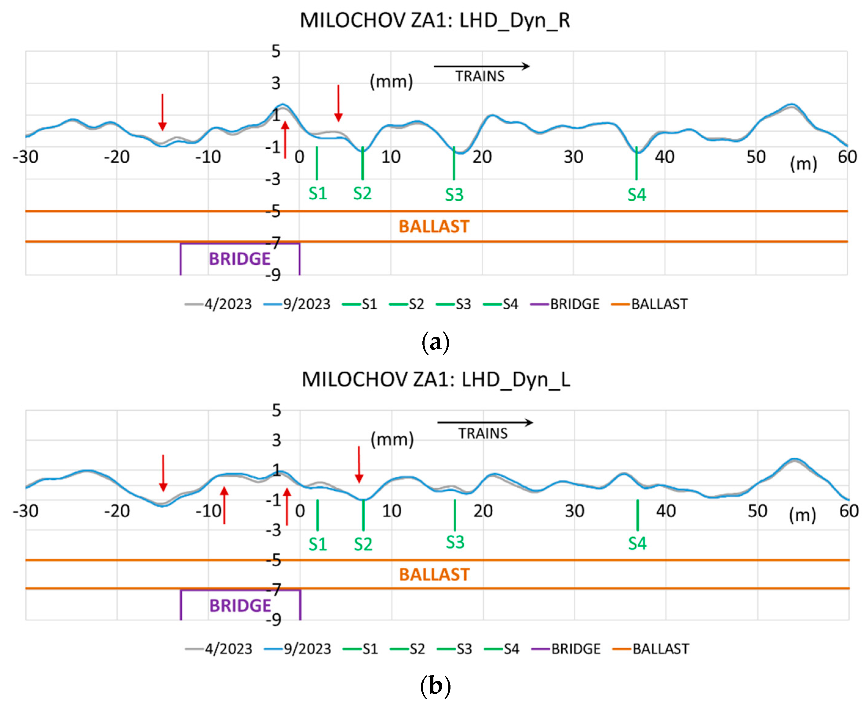
As the first, we point out the bridge object with adjacent parts of track sections, whose measured values of LHD rails R/L are shown in
Figure 1. Markings "ZA1", "ZA2", "BA1", and "BA2" are marked directions of the location of measured transit zones near objects (bridge, tunnel), for example, ZA - towards the city of Zilina, BA - towards the city of Bratislava, 1 and 2 are track numbers. In the figure, the transition zone is in the railway substructure (bridge), where the railway's upper structure forms a classic ballast bed. The arrow represents the prevailing direction of trains (approx. 80 %). We can conclude that the results show characteristic deflections of the track geometry after the train sets pass through the track. The picture shows the bridge object and the positions of the sensors for measuring forces S1 to S4 (they are not the subject of this text and are prepared for subsequent physical measurements in the track, not only monitoring using the KRAB trolley).
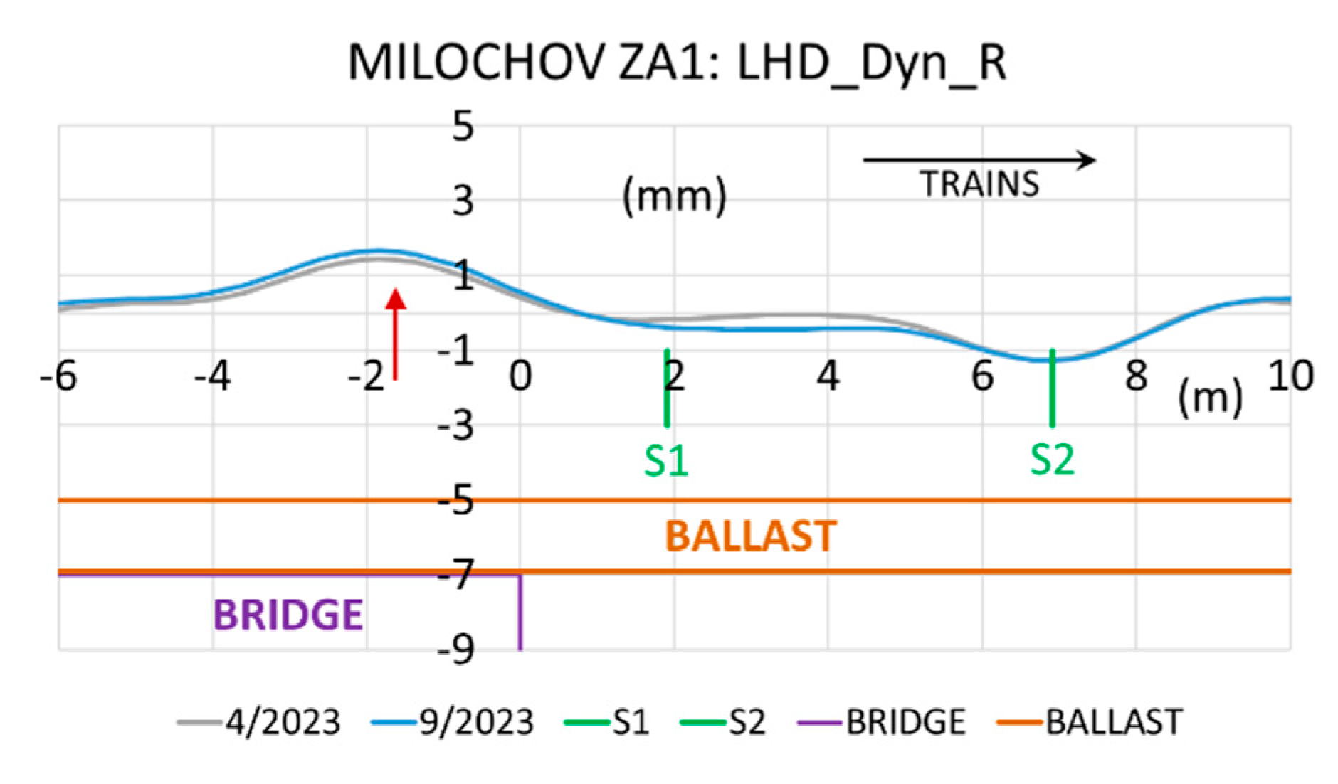
These resulting deflections of the LHD height geometry of the R/L rails are evident in the detailed details of this bridge object in
Figure 2. We note that the height waves at the LHD in the continuous track bed are not as significant as at the ends of the fixed carriageway. This is because a layer of the track ballast dampens the sudden transition change in the railway substructure to the bridge object. As a rule, the track bed is tamped with tamping machines to the required prescribed geometric position and heights of the track (in contrast to a fixed railway track).
Regular tamping works with automatic tamping machines (to the prescribed, designed position and heights) do not allow monitoring the time course of the LHD deflection with the KRAB trolley and similar devices. Evaluations can only be in the interval between two tampings of the track bed, as tamping returns the heights to the same prescribed height position.
This is confirmed by measurements on the fixed railway track near the tunnels and the classic ballasted track (next chapter). A railway line with a classic construction is generally tamped to the projected height (or optimised, prescribed) regularly according to the criteria for evaluating the operational condition in STN 736360-2 [
14] for track monitoring, unlike FRT, where tamping works are not possible. These are operational deviations for the AL level – monitoring limit, IL – intervention or repair limit, and the IAL limit deviation – the limit of immediate intervention in the track.
It is assumed that shocks and shock waves at construction objects under the track bed in the railway substructure. The track will more easily guide the vehicle over these objects in places of stiffness change. This applies if the track is correctly and qualitatively built without subsequent deformations. The FRT demonstrates long-term stability; only when the FRT is affected by a change in the stiffness of the track structure does it adjust in height – it deforms.
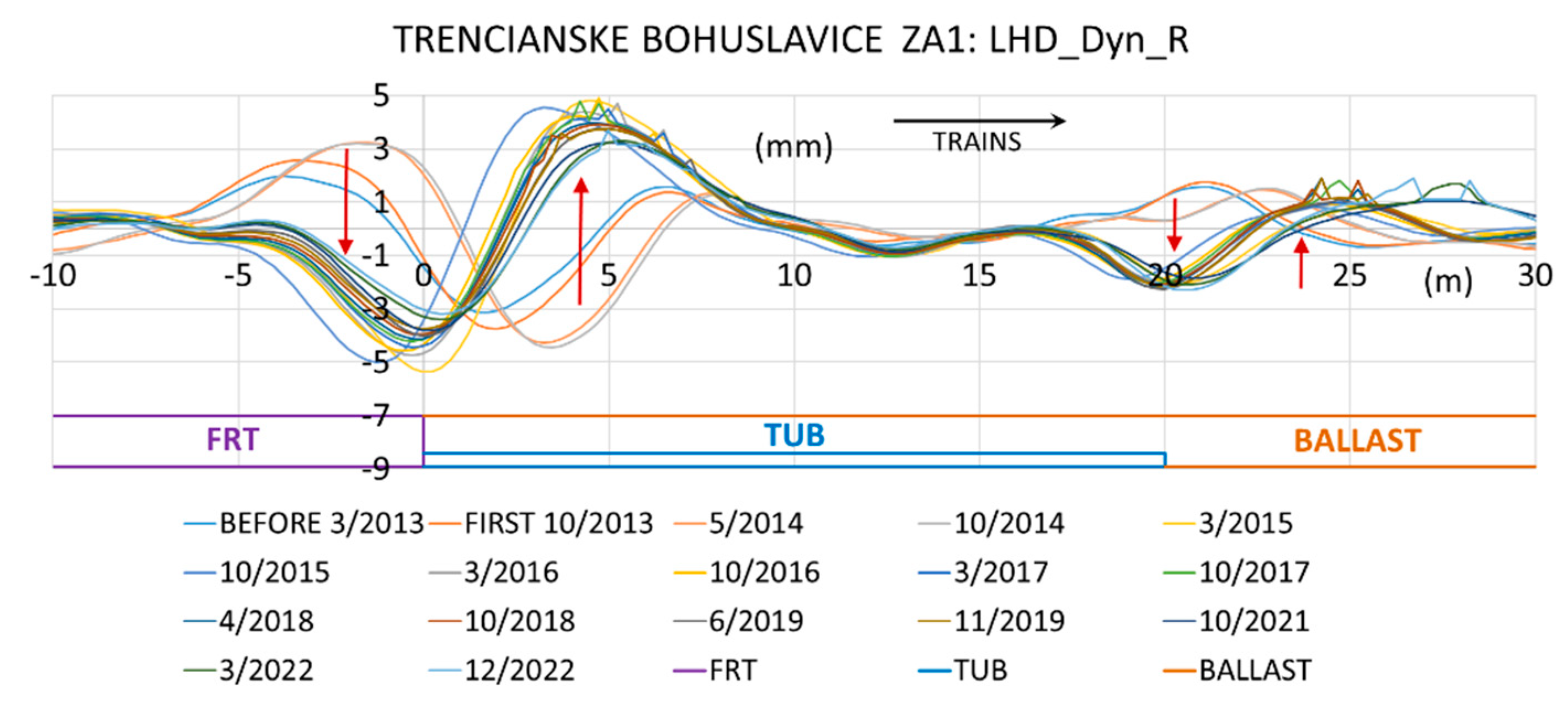
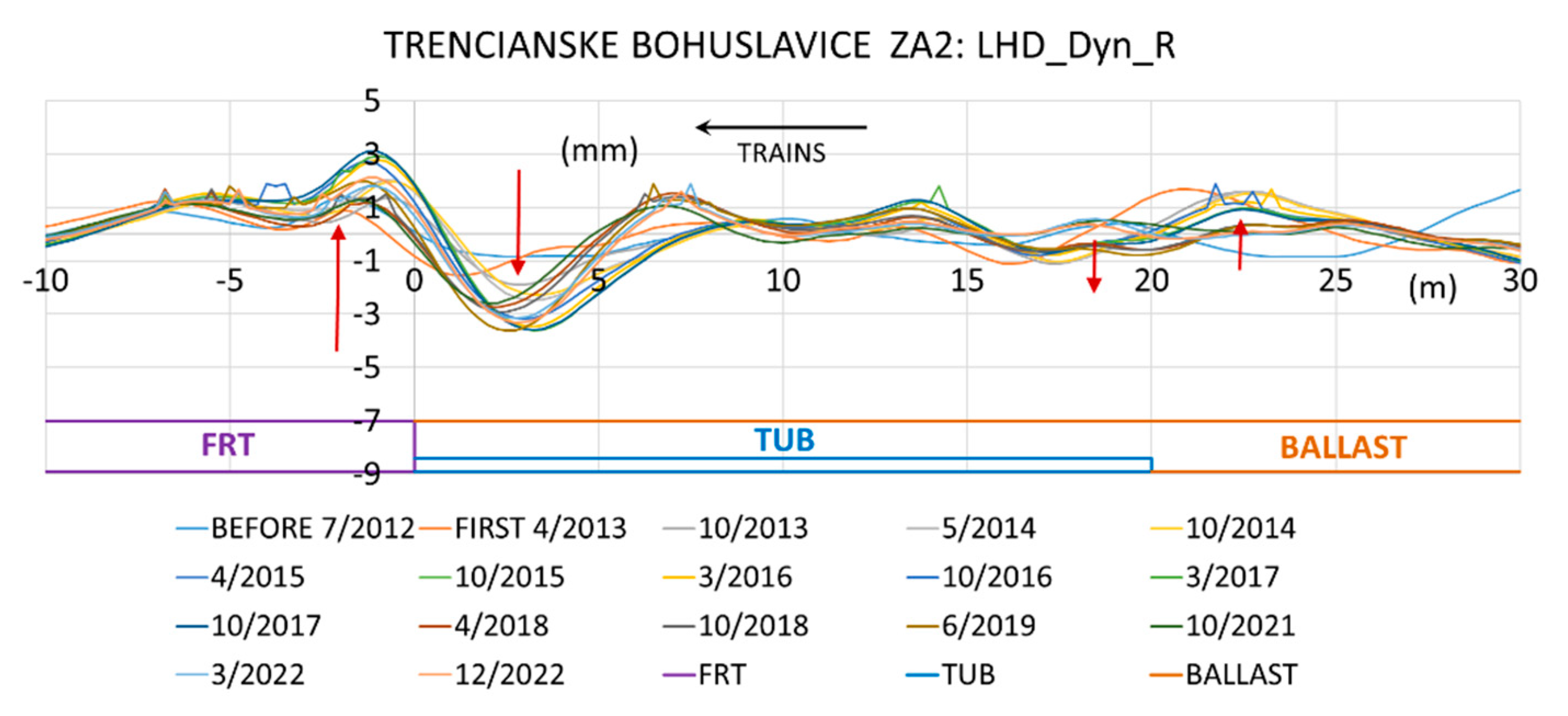
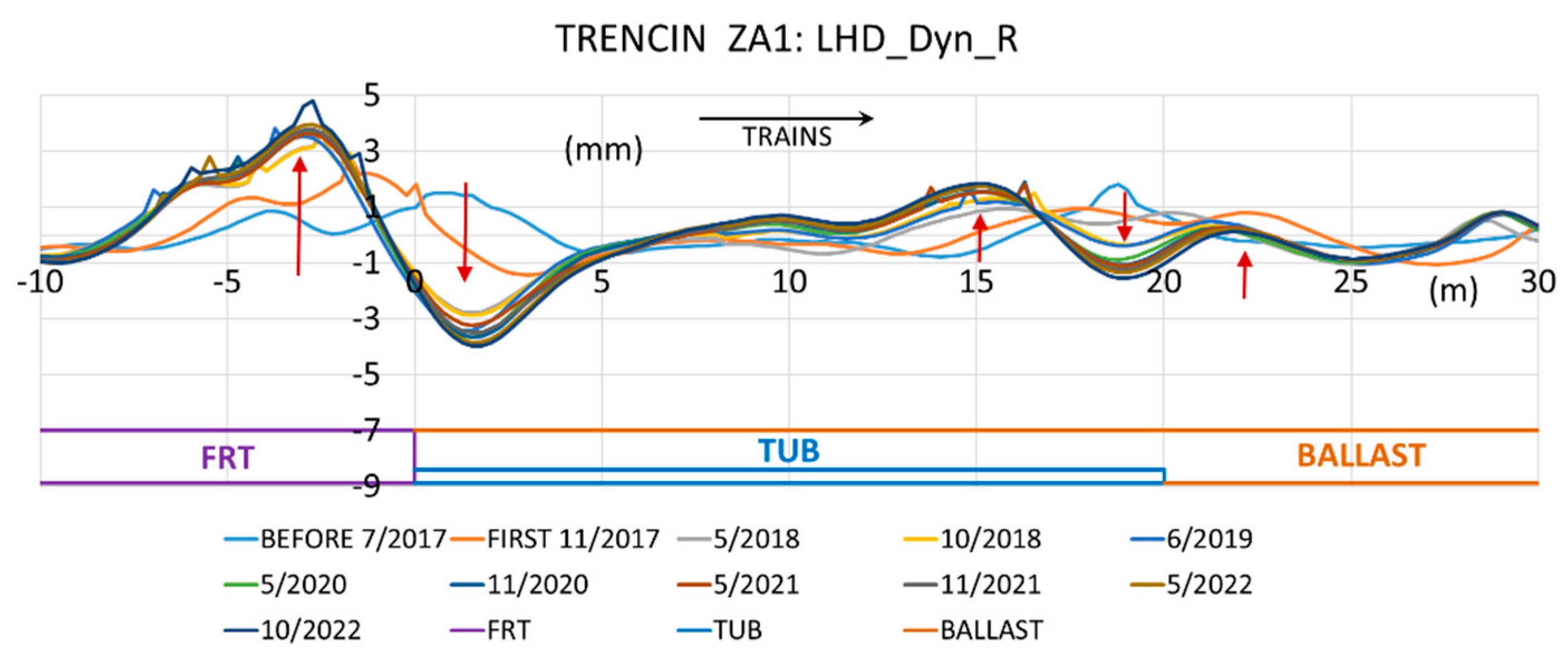
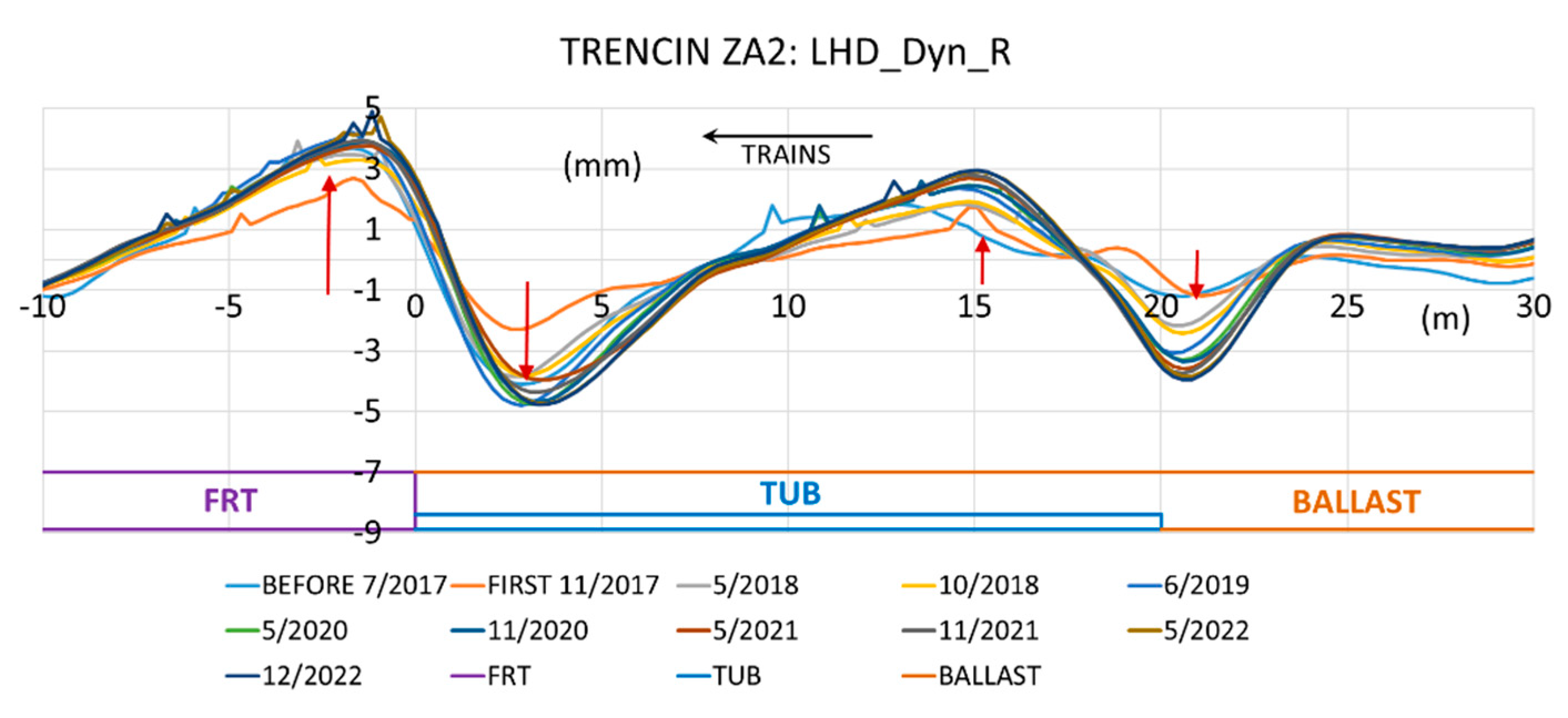
The following results of experimental measurements when changing a track with FRT to a track with a track bed point to problems when changing the stiffness of the railway track. In these places, one structure is interrupted, and there are significant shocks from the wheels of train sets, for example, in
Figure 3,
Figure 4,
Figure 5 and
Figure 6.
To comparison, measurements are presented from the monitoring of a direct transition (at the point of change in track stiffness) from a fixed railway track to a track with a track bed, for example, sections near the Turecky Vrch tunnel near the town of Trencianske Bohuslavice according to figure 3 or near the bridge in the city of Trencin in
Figure 6. Reinforced concrete tubs for the track bed are designed here as transition zones. The zero point “0” represents this transition (“jump”) where structural layers and objects are deformed, and the resulting values are R/L rail geometry position deflections (LHD).
Based on the results of long-term experimental measurements, we can conclude that the transition zone with its beginnings and ends of the fixed railway track (the ends of the FRT), where there is a transition from a reinforced concrete slab to the track bed, or the end of a bridge structure without a track bed, causes more significant problems on the railway line. In contrast to the FRT, in the transition zone from the gravel track bed, for example, at a bridge object located at the railway bottom of the track, Here, the track can be tamped regularly with automatic machine tampers (provided that the structural layers of the railway’s lower substructure under the transition zone can affect their deformations, i.e., the TZ).
During this transition at the end of the FRT structure, a “vertical cut” occurs in the longitudinal profile of the track, causing a significant change in its stiffness. This start or end of FRT at zero point “0” approximately above 1 m in the track bed is tamped poorly or not at all. Also, for this reason, “jumps” (deformation waves) arise, created by the forces of the wheels of train sets at these points.
The research shows that the most significant height wave of the change in the geometry of the R/L rails occurs at the transition point, and in the case of the constructed reinforced concrete tub, also at its end, but approx. with half the value of the height/depth of the wave (“double jump” height curve, in this case, the length of the tub is 20 m). When the trains travel in the opposite direction, the material at this point is pushed under the fixed track or the transitional reinforced concrete tub, or the structural layers of materials under the concrete objects or the reinforced concrete tub of the transition zone are deformed.
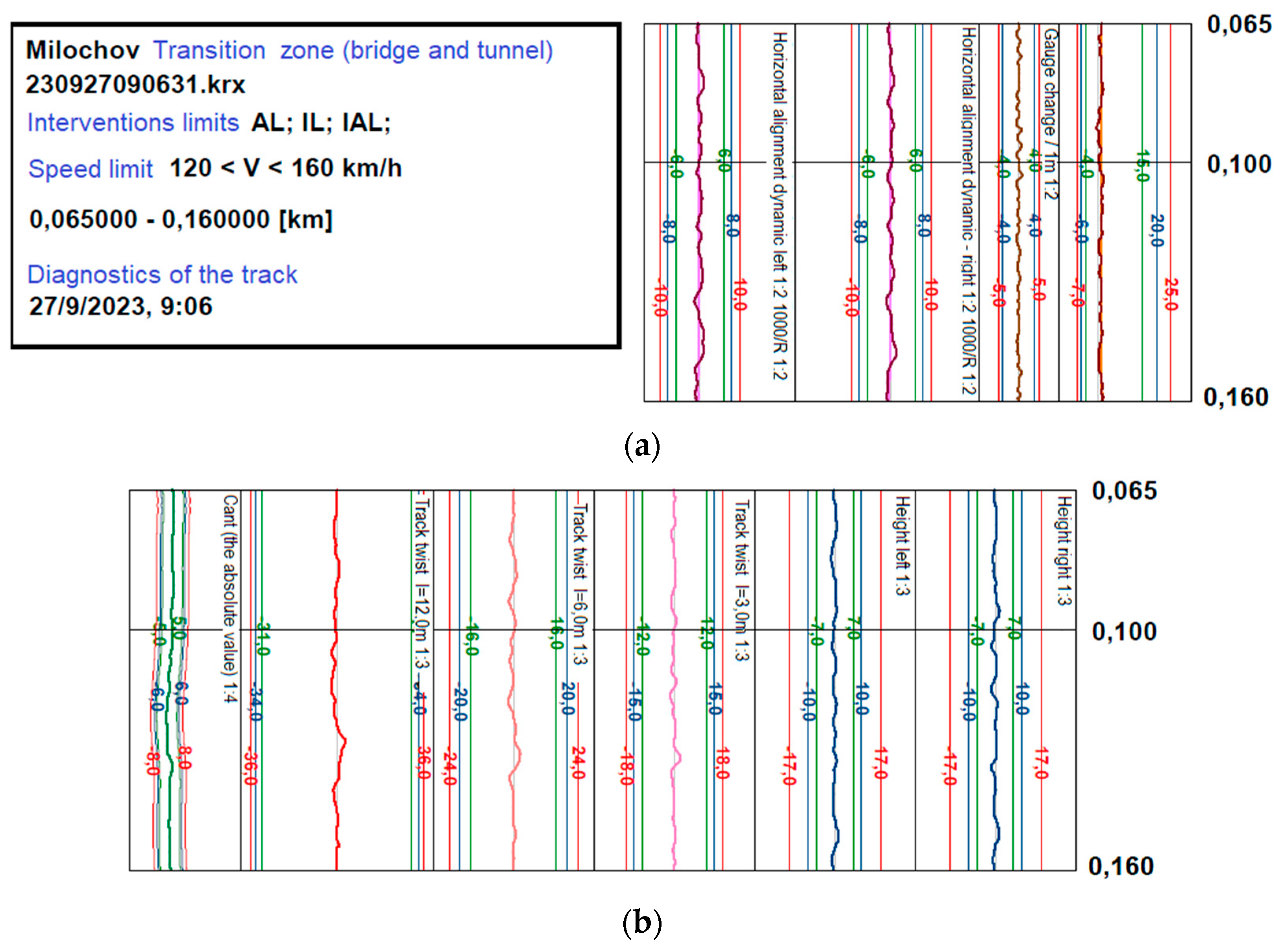
Even if these height waves of the geometric position of the R/L rails (LHD) are detected, solved and analysed, the track in the given section meets the criteria of operational deviations. As an illustration, the resulting graphs from measurements by the continuous KRAB trolley with all its parameters are shown in
Figure 7. The primary task of the research is to reduce the effects of shocks from the wheels of train sets, vibrations, deformations, etc., on objects of track construction, including stress and wear of structural parts of train sets, and increase the comfort of driving on the track (people, goods). If these deformations are not considered, the geometric position and heights may collapse at the point of change in track stiffness.
3.2. Tunnel Portals
Other track stiffness changes, such as tunnel portals, behave similarly to the vertical deformation deflections of the track geometry.
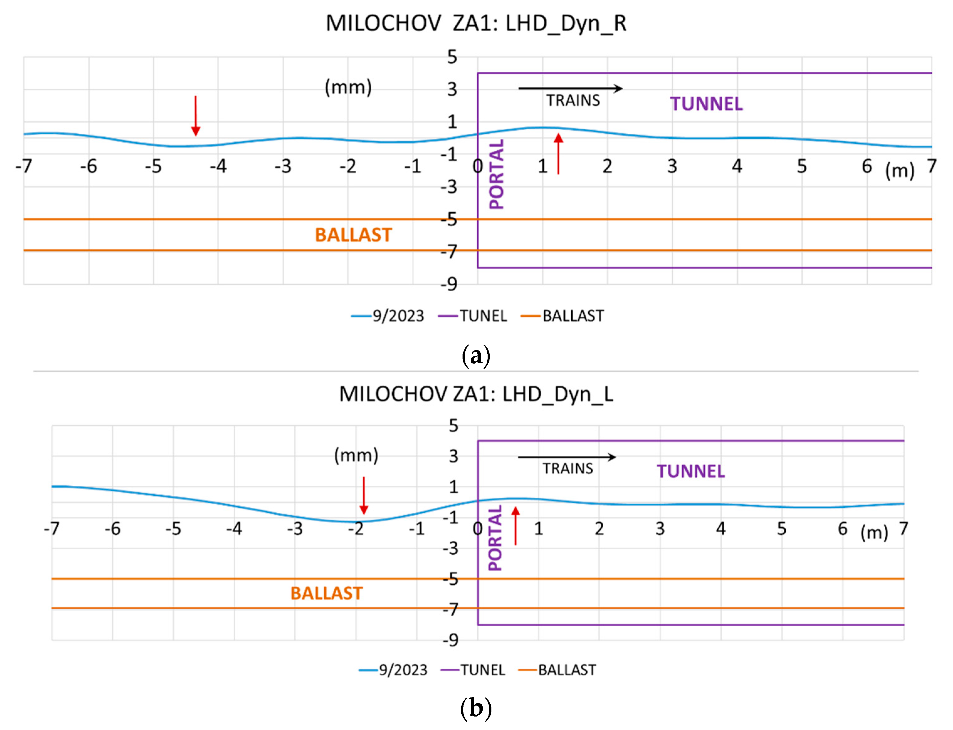
Data are monitored in the measured research section of the transition zone near the portal of the Milochov tunnel, according to
Figure 8, where there are height changes on the R/L rails. Since it is a classic construction of a railway line with a track bed, the section is tamped with automatic tamping machines to the prescribed geometric position and height of the track according to the AL, IL, IAL criteria according to the standard STN 736360-2 [
14].
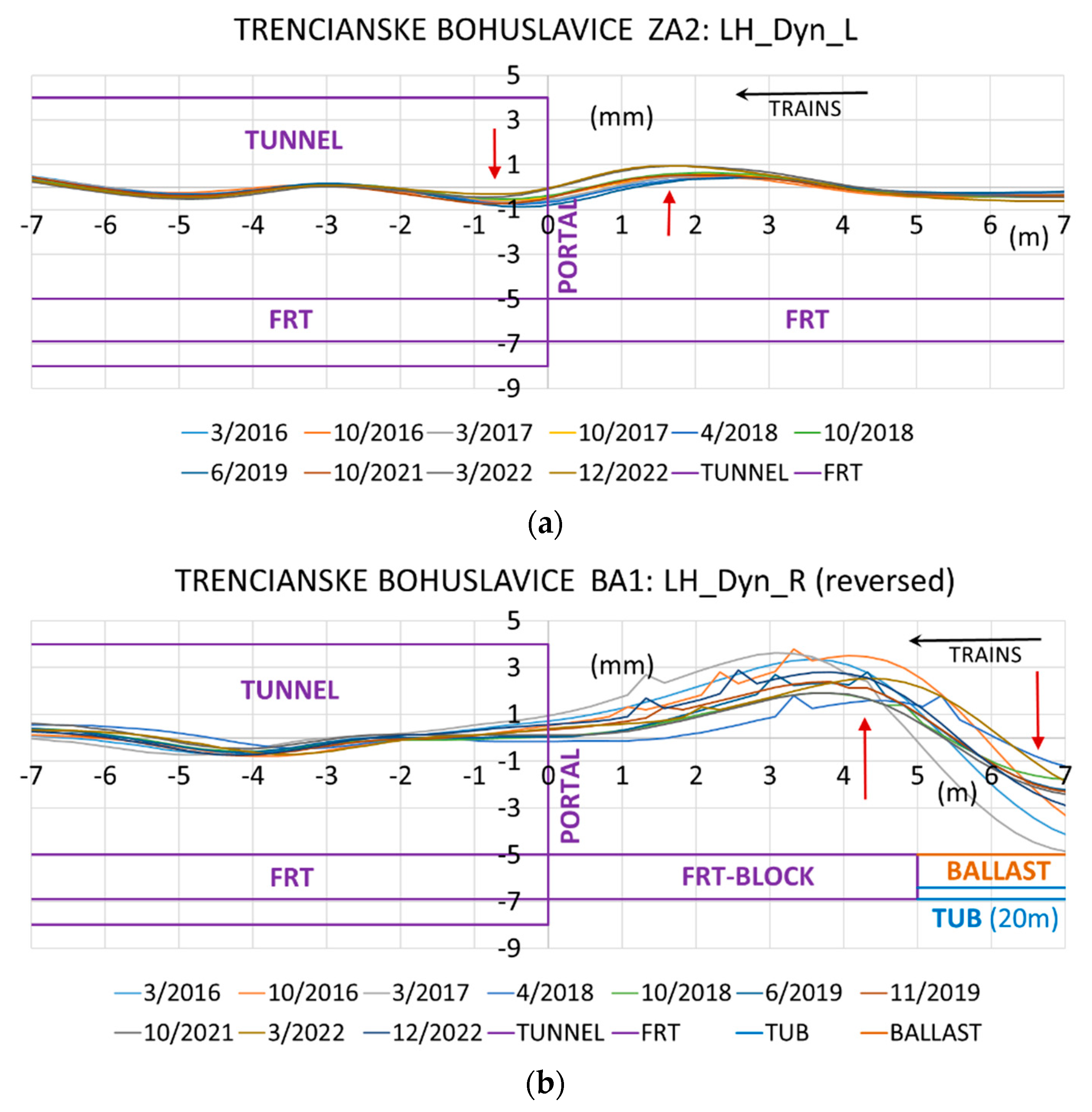
In the case of tunnels with FRT, the research monitoring registered the height changes of the wave of the geometrical position of the track (tunnel portals), where it is proven that there is a pushing of the material into the part of the track with its softer stiffness of the track with the subsequent pushing out of the material of the structural layers at zero point “0” of change. There is also an uplift of the track geometry at the beginning of the reinforced concrete track,
Figure 9b (
Figure 9a is OK), where there is also a terminating reinforced concrete block with an approximate length of 5 m.
The driving of various vehicles during tunnel maintenance, which enters the tunnel from the road network in this location, or the loading of parts and machines at the tunnel portals can contribute to the deformations to a certain extent. Alternatively, there can be a double transition zone, i.e., the end of the fixed carriageway and the associated tunnel portal (2 transition zones in a row in
Figure 9b).
Experimental measurements were carried out using different structural combinations of the railway tracks at the tunnel portals. The results with a continuous track bed were first presented in the paper, but the results are more interesting regarding the results for the railway track formed by the FRT-reinforced concrete track or slabs. In the case of continuous FRT construction at the portal site, it is influenced by this tunnel portal (its massive construction), for example, by the FRT track in front of the portal, or vice versa by the fall or lift of the portal. For a long time, research was mainly carried out for portals with a sudden structural change in the stiffness of the carriageway, where the FRT ends (designed only in the tunnel tube). In these cases, the proposed reinforced concrete tub for the track bed is before the tunnel portal. These transition zones have a proposed reinforced concrete block glued to the foundations of the portal, and here, a “cut” occurs between these objects; for example, they are presented in research publications [
9,
10] and [
12].
4. Common Characteristics of Results and Comments
Based on the mentioned long-term observations of the transition zones, it is possible to state certain characteristic basic features of the behavior of the geometric position of the R/L rails. Differences arise in transition zones with a fixed track (FRT), for example, with a reinforced concrete tub, or a track with only a track bed and built-in bridge objects, tunnel portals, culverts in the railway lower substructure, etc. We have to keep in mind that the track bed (unlike the reinforced concrete track with FRT) is tamped regularly based on design or operational criteria, and it is difficult to determine the behavior of the objects below it because they have the final adjustment of the geometric position and heights of the track made by machine tampers. On the contrary, the track with FRT cannot be tamped, modification is impossible or exceptional (change of pads under the rails with different thicknesses, breaking the reinforced concrete slabs and building a new one), but they have long-term sustainability of the geometric position of the track. The problem is only the contact zones in case of a sudden change in the stiffness of the track of these two systems.
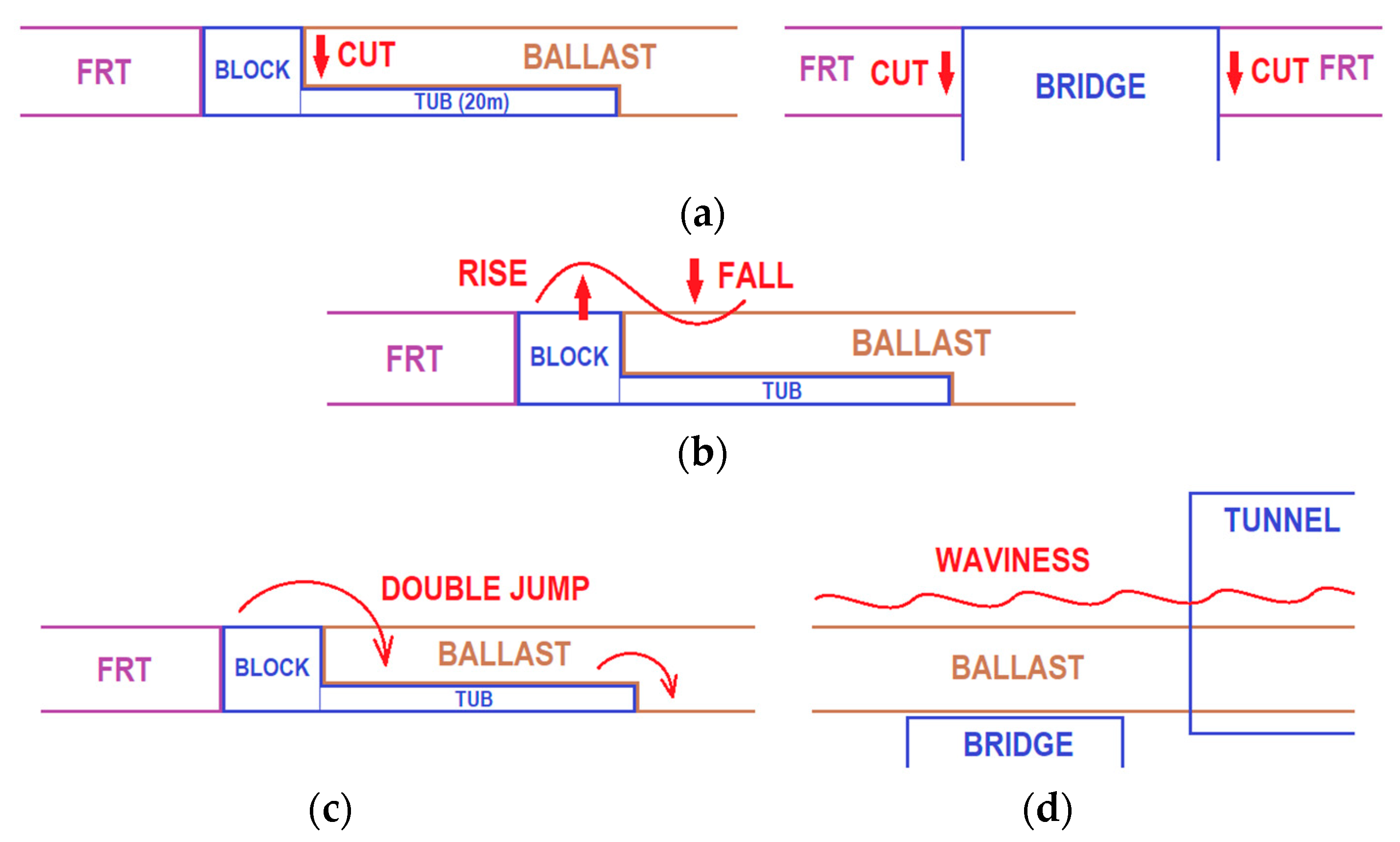
Through monitoring and inspection of the railway track, it has been proven that there are shocks, vibrations, jumps, and pushing and pushing of the materials of the structural layers in the transition zones, according to the diagrams in
Figure 10.
Figure 10 summarises all the detected characteristics on the track with FRT (
Figure 10a-c). However, if the track without FRT is only with a track bed, only the undulation of the geometric position of the track heights is presented (
Figure 10d). In this case, there is no change in track stiffness directly under the rails and sleepers (continuous track bed) because the track is tamped using tampers.
With a continuous track bed, it is not possible to determine during expert measurement the behavior of the geometric position and height of the track depending on the built-in object under the track bed, as even here, the track is tamped regularly or at prescribed intervals (AL, IL or IAL). The geometry of the track is characterised by height waviness in small height changes of ± 2 mm. We have to note that if a bridge, tunnel portal or culvert has a continuous track bed, we cannot record it, for example, with the tunnel portal in
Figure 8 or
Figure 10d. Indeed, if the track is not tamped, its deformations will be recorded. If the continuous track bed ends at a bridge abutment or a tunnel portal, we consider it a classic transition zone, similar to the end of a fixed railway track.
5. Conclusions
The classic construction of the railway upper structure and the construction of the so-called fixed reinforced concrete roadway (FRT), or ballast-less superstructure and in the case of constructions of the body of the railway substructure. Because in the Slovak Republic, this issue is not sufficiently addressed in the relevant legislative documents, it is necessary to proceed with their amendment in connection with the long-term experience of advanced railway administrations and to incorporate European standards into the proposals of designers in railway construction.
Based on experimental measurements of selected test sections established on the European railway corridors, the current options for solving transition zones must be optimised using numerical modelling, or new solutions must be proposed. From this aspect, these solutions must not only respect the experiences gained from the research of the given issue but also accept new experiences and perspectives on the solution of transition zones by advanced railway administrations. At the same time, the effort will be to apply, to the maximum extent possible, innovative structural materials and elements in the construction of the transition zones, not only in the part of the construction of the railway superstructure but also in the railway substructure (different types and shapes of structural layers and their different materials, reinforced concrete plates and wedges, small pilots, etc.). From this point of view, the expected benefit will be the differentiation of structural materials and elements and their influence on achieving a numerically optimal gradation of roadway stiffness between structures with different stiffnesses, which occur in large quantities on every railway line.
A relevant contribution will be, in addition to the optimisation of the applied current transition zones, their modification, i.e. preparation of structurally and materially new constructions of transition zones for different areas of different stiffness parts on modernised railway infrastructure lines, respecting actual operating conditions (track speeds, type and number of trains) and also various parts of construction objects of the underlying structure (bridges, tunnels, culverts, etc.). Several years of track modernisation experience show that increased investments in the quality of transition zones can increase driving comfort and the life of the track and reduce the costs of its maintenance and repairs (by increasing the time intervals between the necessary AL, IL or IAL interventions). At increased speed, the running of trains along these transition zones and their subsequent track sections will be more reliable and safer with increased resistance to their deformations by reducing the effects of the forces acting on the given places. Numerical modelling of these elements and the forces acting between them (from the chassis wheels through the R/L rails to all layers of the railway body) is a subsequent step of the new proposed projects [
15].
Author Contributions
Conceptualization, S.H. and J.I.; methodology, S.H.; software, S.H. and E.V; validation, S.H., J.I.; formal analysis, S.H.; investigation, S.H. and J.I.; resources, S.H. and J.I.; data curation, S.H.; writing – original draft preparation, S.H. and E.V.; writing – review and editing, S.H. and J.I; visualization, S.H.; supervision, S.H. and J.I.; project administration, S.H.; and J.I; funding acquisition, S.H. and J.I. All authors have read and agreed to the published version of the manuscript.
Funding
This research received no external funding.
Acknowledgments
The presented parts of the paper were created within the framework of the research activities VEGA 1/0643/21 [16] by the Department of Geodesy and Railway Engineering at the Faculty of Civil Engineering of the University of Zilina (FCE-UNIZA). The authors would like to thank the editor and reviewers for their constructive comments and valuable suggestions for improving the quality of the article.
Conflicts of Interest
The authors declare no conflict of interest.
References
- KRAB. KZV – Commercial Railway Research. 2024, Available online: S-light EN.indd (kzv.cz) (accessed on 5 August 2024).
- Sanudo, R.; Jardi, I.; Martinez, J.C.; Sanchez, F.J.; Miranda, M.; Alonso, B.; Olio, L.; Moura, J.L. Monitoring track transition zones in railways, Sensors. 2022, 20(1), 76. (accessed on 17 September 2024). [CrossRef]
- Park, S.; Kim, DS.; Kim, U.; Jeong, S. Low Compressibility at the Transition Zone of Railway Tracks Reinforced with Cement-Treated Gravel and a Geogrid under Construction, Applied Sciences. 2022, 12(17), 8861. (accessed on 12 July 2024). [CrossRef]
- Jain, A.; Metrikine, AV.; Steenbergen, MJMM.; van Dalen, KN. Railway transition zones: evaluation of existing transition structures and a newly proposed transition structure, International Journal of Rail Transportation. Taylor & Francis. 2023, 21p. (accessed on 8 July 2024). [CrossRef]
- Jain, A.; Metrikine, AV.; Steenbergen, MJMM.; van Dalen, KN. Design of railway transition zones: A novel energy-based criterion, Transportation Geotechnics. Elsevier. 2024, 46, 101223, 12p. (accessed on 5 June 2024). [CrossRef]
- Idczak, W.; Lewandrowski, T.; Pokropski, D.; Rogojsz, G.; Rudnicki, T. Monitoring track transition zones in railways, Sustainability. 2022, 14(7), 4118. (accessed on 20 June 2024). [CrossRef]
- Hu, P.; Liu, H.; Tang, YZ.; Lin, YL. Field Investigation of the Dynamic Response of Culvert-Embankment-Culvert Transitions in a High-Speed Railway, Materials. 2023, 16(17), 5832. (accessed on 4 February 2024). [CrossRef]
- Park, S.; Kim, J.Y.; Kim, J.; Lee, S.; Cho, K.H. Analysis of Dynamic Characteristics of Deformed Concrete Slab Track on Transition Zone in High-Speed Train Line According to Train Speeds, Applied Sciences. 2020, 10(20), 7174. (accessed on 10 July 2024). [CrossRef]
- Hodas, S.; Izvoltova, J.; Chromcak, J.; Bacova, D. Monitoring the Geometric Position of Transition Zones to Increase the Quality and Safety of Railway Lines, Applied Sciences. 2022, 12(12), 6038. (accessed on 15 April 2024). [CrossRef]
- Hodas, S.; Pultznerova, A.; Izvoltova, J. Protection of Structural Layers of Transitions Zones on Railways against Freezing, Using Materials with a Low Coefficient of Thermal Conductivity. Buildings. 2022, 12(6), 821. (accessed on 10 September 2024). [CrossRef]
- Hodas, S.; Vrchovsky, E.; Pultznerova, A. Monitoring and expertise of sections with a sudden change in railway track stiffness - transition zones of bridges. Buildings, 13(8), 2023, 2056. (accessed on 7 July 2024). [CrossRef]
- Hodas, S.; Pultznerova, A.; Vrchovsky, E. Experimental monitoring of transition zones in railway tunnels. Civil and Environmental Engineering, 19(2), 2023, 464-473. (accessed on 18 July 2024). [CrossRef]
- Izvolt, L. et al. VEGA 1/0084/20. Numerical and experimental analysis of transition zones of objects of structures of railway superstructures and objects of formation substructure. Scientific research, Dept. of Railway Engineering, Faculty of Civil Engineering, University of Zilina, Zilina, http://svf.uniza.sk/kzsth, VEGA - Ministry of Education. Science and research of the Slovak Republic, Bratislava, Slovakia; 2020-2023. 2020, Available from <http://www.minedu.sk/about-the-ministry/ >.
- STN 73 6360-2:2015 - Rev. O1 03/18:2018. Railway applications. Track, Part 2: Acceptation of construction works, maintenance works and assessment of service condition track gauges 1435 mm. Slovak Standard, 2018.
- Hodas, S. et al. VEGA 1/0236/25. Analysis, diagnostics and modification of structural parts in places with a significant change in the stiffness of the railway track. Submitted new scientific research in the evaluation process to the Dept. of Railway Engineering, Faculty of Civil Engineering, University of Zilina, Zilina, http://svf.uniza.sk/kzsth, VEGA - Ministry of Education. Science and research of the Slovak Republic, Bratislava, Slovakia; 2025-2028. 2024, Available from <http://www.minedu.sk/about-the-ministry/ >.
- Izvoltova, J. et al. VEGA 1/0084/20. Analysis of spatial deformations of the railway track targeted by terrestrial laser scanning. Scientific research, Dept. of Geodesy and Railway Engineering, Faculty of Civil Engineering, University of Zilina, Zilina, http://svf.uniza.sk/kzsth, VEGA - Ministry of Education. Science and research of the Slovak Republic, Bratislava, Slovakia; 2021-2024. 2024, Available from <http://www.minedu.sk/about-the-ministry/ >Author 1, A.; Author 2, B. Book Title, 3rd ed.; Publisher: Publisher Location, Country, 2008; pp. 154–196.
|
Disclaimer/Publisher’s Note: The statements, opinions and data contained in all publications are solely those of the individual author(s) and contributor(s) and not of MDPI and/or the editor(s). MDPI and/or the editor(s) disclaim responsibility for any injury to people or property resulting from any ideas, methods, instructions or products referred to in the content. |
© 2024 by the authors. Licensee MDPI, Basel, Switzerland. This article is an open access article distributed under the terms and conditions of the Creative Commons Attribution (CC BY) license (http://creativecommons.org/licenses/by/4.0/).
