1. Introduction
Wind turbine loads are heavily influenced by the operating conditions and environments [
1]. Therefore, it is defined by the standards [
2,
3] that blade designers/manufacturers need to run thousands of load cases that simulate wind turbines under various conditions in the design and certification processes. The test cases vary from normal power production operations (typically aimed at fatigue loads analysis) to the extreme conditions when the turbine is shut-down, either in parked or idling modes. The parked/idling conditions are typically applied for high wind speed cases above the cut-out wind speed of the turbine. In such conditions, wind turbine controller is normally no longer active when no backup power supply is available. Hence, the blade is prone to operate at large angle of attack depending on the yaw angle, and it remains locked at this position. This could lead to strong unsteady characteristics and the aeroelastic behavior of the blade can be dangerous for its own structural integrity. In these conditions, the unsteady aerodynamic effects on the blade can manifest as dynamic stall when the blade sections operate at high angles of attack.
The consideration of unsteady aerodynamic effects becomes even more important in the last few decades since the blade size has increased considerably, making the blade more slender and flexible. The aeroelastic characteristics of such long blades are not well understood where instability and vibrations often become huge concerns and limiting factors for designs. Despite this clear environmental challenge, wind turbine blades are required to be able to survive even in harsh conditions as defined in the set of loads calculation within the IEC [
2] and DNV [
3] standards.
Wind turbine aeroelastic response is strongly affected by the amount of damping on the blade itself, that can generally be divided into the structural and aerodynamic damping. When the total damping of the blade becomes negative, instability of the blade is enhanced. It is well understood that the edgewise direction is prone to negative damping conditions. The structural damping represents the structural design and the material used to manufacture the blade itself, and it is relatively easy to estimate with high confidence level. However, predicting the aerodynamic damping is not a trivial task because it can significantly change depending on the operating conditions of the turbine. This type of damping is affected by the acting forces on the blade, which alter the angle of attack due to elastic response.
The aeroelastic phenomenon in these extreme conditions is highly unsteady, and as a direct consequence, the induction-based blade element momentum theory commonly adopted in engineering tools needs to be corrected using a dynamic stall model. Examples of such models are the Beddoes-Leishman (BL) model [
4], Larsen model [
5], Øye model [
6], Snel model [
7], Risø model [
8], IAG model [
9,
10], ONERA model [
11], Boeing-Vertol model [
12], etc.
Understanding how these dynamic stall models behave in challenging conditions will be an important factor to properly estimate the impacts on aeroelastic characteristics. Several studies have attempted to evaluate the dynamic stall characteristics of wind turbines in standstill conditions (parked/idling) [
13,
14,
15,
16,
17,
18,
19,
20], and it is commonly believed that dynamic stall models tend to underestimate the true aerodynamic damping due to inaccurate hysteresis predictions [
21]. Hansen [
14] provided a proposal for an improved modal analysis to improve the understanding of wind turbine stability. Sarkar and Bijl [
22] evaluated non-linear aeroelastic behavior of an oscillating airfoil during stall-induced vibration in two-dimensional environments. Wang et al. [
15], for instance, focused their studies on the linear model predictions when using the BL model and the ONERA model. Bir and Jonkman [
23] investigated the aeroelastic instability on a 5 floating MW wind turbine, and pointed out the distinction between aeroelastic instability and resonance, where the latter requires external excitation at a distinct frequency. Tibaldi et al. [
24] performed a numerical investigation on wind turbine resonant vibrations, where it was highlighted that depending on the external excitation, different aeroelastic modes can be excited. The responses of different dynamic stall models in wind turbine under standstill conditions are further evaluated for example by Wang et al. [
15], Faber [
25], Bangga et. al. [
13], Andreou [
26], Bangga and Yu [
17]. In Ref. [
27], commonly adopted engineering approaches were reviewed and discussed. Horcas et al. [
28] provided an improved understanding of standstill flow conditions by adopting high fidelity computational fluid dynamics (CFD) approaches, but a direct adoption of the studies to practical engineering methods are still yet to be explored.
The present paper is specifically aimed at addressing the critical issue on how sensitive dynamic stall models actually are when they are exposed to dynamic excitation in edgewise direction. To the best of the author’s knowledge, comprehensive studies in this area are lacking for extremely large wind turbine blade structure. This is especially crucial when different dynamic stall models and excitation frequencies will be considered that lead to uncertainties in wind turbine blade design and certification processes. Considering the current state-of-the-art, the present paper investigates the aeroelastic sensitivity of a large wind turbine blade using three different dynamic stall models commonly applied in the designs, namely (1) the Øye model [
6], (2) the incompressible version of the BL model (Risø model [
8]) and the newly developed IAG model [
10]. The studies start by comparing different dynamic stall models against a pitching airfoil case, where experimental data is available. Then the investigations are extended by exciting the rotor blade by means of an oscillating wind at various frequencies, ranging from below to above the first edgewise modal frequency of the blade. The growth of the angle of attack response is monitored at different wind speeds to quantify the direct influence of the unsteady aerodynamic models on the aeroelastic responses.
The present paper is organized as follows. method provides a description of the employed code, approaches and the test cases of interest. The results are discussed in resultsOSUValidation to resultstwist starting by the comparison of the pitching airfoil data, then continued with the aeroelastic response at the blade level. Finally, the paper will be concluded with suggestions for follow up studies in conclusion.
2. Methodology
2.1. Wind Turbine Design Code Bladed
Bladed is an engineering tool used in numerous wind turbine industries for designs and certifications as well as in research environment. The code solves aeroservohydroelastic problems of wind turbines by utilizing blade element momentum (BEM) theory coupled with structural and control algorithms. The rotor aerodynamic solutions are obtained using time-marching approaches of the induced velocities at each blade section. Bladed uses a full local BEM approach implementation [
8,
29]. The solutions are coupled with the structural dynamic models that adopt a multibody dynamics approach. A multi-part blade method is adopted to allow the structural dynamic equations to model larger deflections using a linear beam theory. Efficient solutions of these complex nonlinear problems are made possible via the fixed-step implicit Newmark-
integrator. Several publications documented the verification studies of the Bladed code performance and accuracy [
10,
30,
31]. Bladed version 4.16.0 is utilized in the present studies.
In the present studies, three dynamic stall models in Bladed are adopted, namely ye [
6], Beddoes-Leishman (BL) [
8,
29] and a recently developed IAG model [
10]. The incompressible version of the BL model [
8,
29] has been widely adopted in wind turbine designs and can be considered as the state-of-the-art model. Although the model works sufficiently well for most conditions, the accuracy of the model is constantly challenged when it operates at complex inflow conditions at large yaw misalignment. This implies that the angle of attack of the blade sections can be significantly large [
10]. The IAG model has recently been developed specifically for wind turbine applications and has been tested against experimental data at various conditions [
9,
10]. The robustness and applicability of the IAG dynamic stall model for wind energy field were further improved in the second generation model by enabling a formulation in the state-space representation, as well as by removing the compressibility effects and by decreasing the number of required constants [
10]. In Ref. [
10], it was demonstrated that the IAG model performs well against experimental data and it outperforms other models when the airfoil operates at large angles of attack beyond stall, and the tests were carried out at various reduced frequencies and amplitudes. The IAG model was further compared against other dynamic stall models for various load cases in Refs. [
13,
17].
2.2. Blade Specification and Airfoil Data Treatment
The present studies mainly adopt a blade constructed by the S809 airfoil. This airfoil is chosen because there is experimental data available both for static and dynamic conditions [
32]. Thus, validation of the results for pitching airfoil case will be possible. This airfoil has a relative thickness of
= 21% and was measured at a Reynolds number of a million. For the present studies, results based on the airfoil equipped with a leading edge grit (turbulator) will be adopted. This is done to simulate the "soiled" effects on a wind turbine blade in field.
In the present studies, the blade geometry of the IEA 15 MW reference wind turbine version 1.1 is adopted [
33]. The blade is selected since it is representative for the current blade design that is associated with all complexity and highly flexible structures. The blade has a length of about 117 m. Starting from 91.33 m of the blade length, the relative thickness of the airfoil section (relative to chord) is about 21%. In the present studies, the IEA 15 MW reference wind turbine blade is modified by replacing the applied airfoils at all blade sections. First, the airfoil data from 91.33 m of the blade length is replaced with the S809 airfoil. The remaining parts of the blade up to the root area are then generated based on interpolation (according to relative thickness). The root of the blade adopts a cylinder with a constant drag coefficient of about 0.35. This process is illustrated in
Figure 1 and
Figure 2. It is noted that most investigations will be focused on the dynamic response of the blade section at 93.68 m except stated otherwise. A more realistic test case can be designed by using the actual blade airfoils without modification. However, this will involve complex behavior of different airfoils with different stall characteristics. This makes it difficult to draw conclusions and to analyze further. Thus, the simplification done in the present paper is used as a starting point.
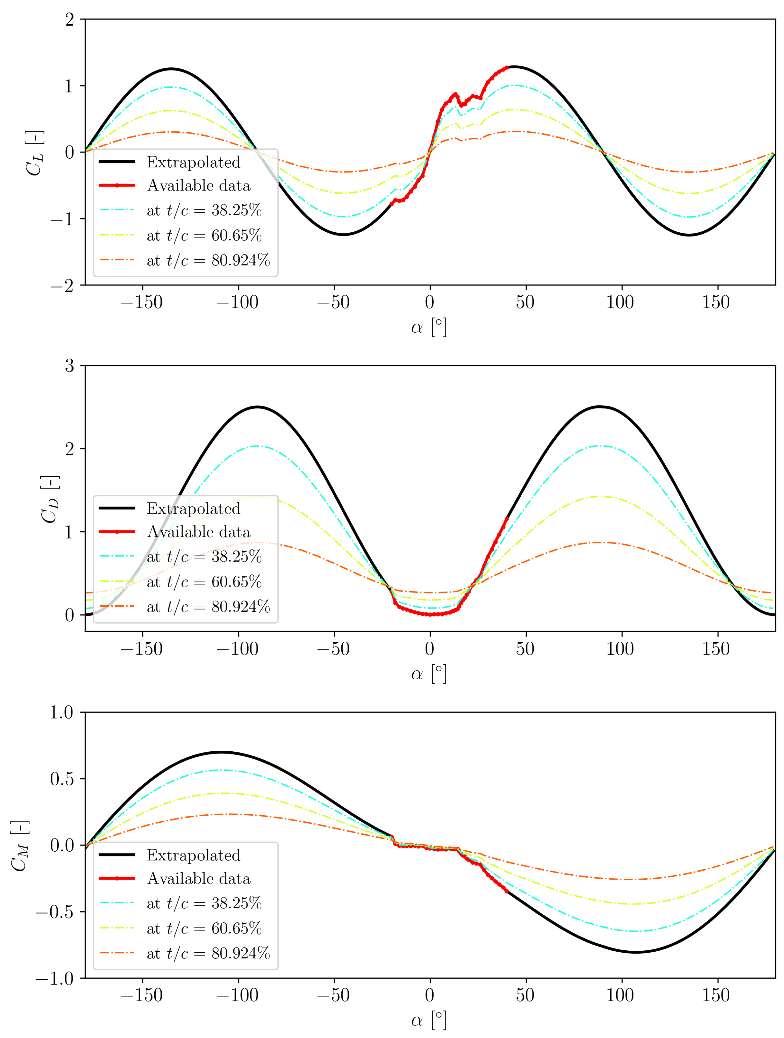
Since the S809 airfoil was measured only to a limited range of the angle of attack (
), it is a common practice to extrapolate the data to cover
= -180
∘ to
= +180
∘ regime. In this paper, a modified Viterna approach [
34] is adopted and the results are plotted in figPolarExtrapolated. The description of the method is given in
Appendix A. The usage of the extrapolated data will affect the accuracy of wind turbine calculations. The reconstruction accuracy deteriorates the shorter the data one has. A 360
∘ extrapolation can be used in early stage of wind turbine designs to give a rough idea about the turbine loads before any further detailed assessments are made. It is highlighted in Ref [
35] how the dynamic calculations are influenced by the steady data reconstruction.
The extrapolated airfoil is then interpolated based on the relative thickness distribution shown in
Figure 3. Toward the root area, cylinder is applied and the interpolation results at various relative thicknesses are shown in
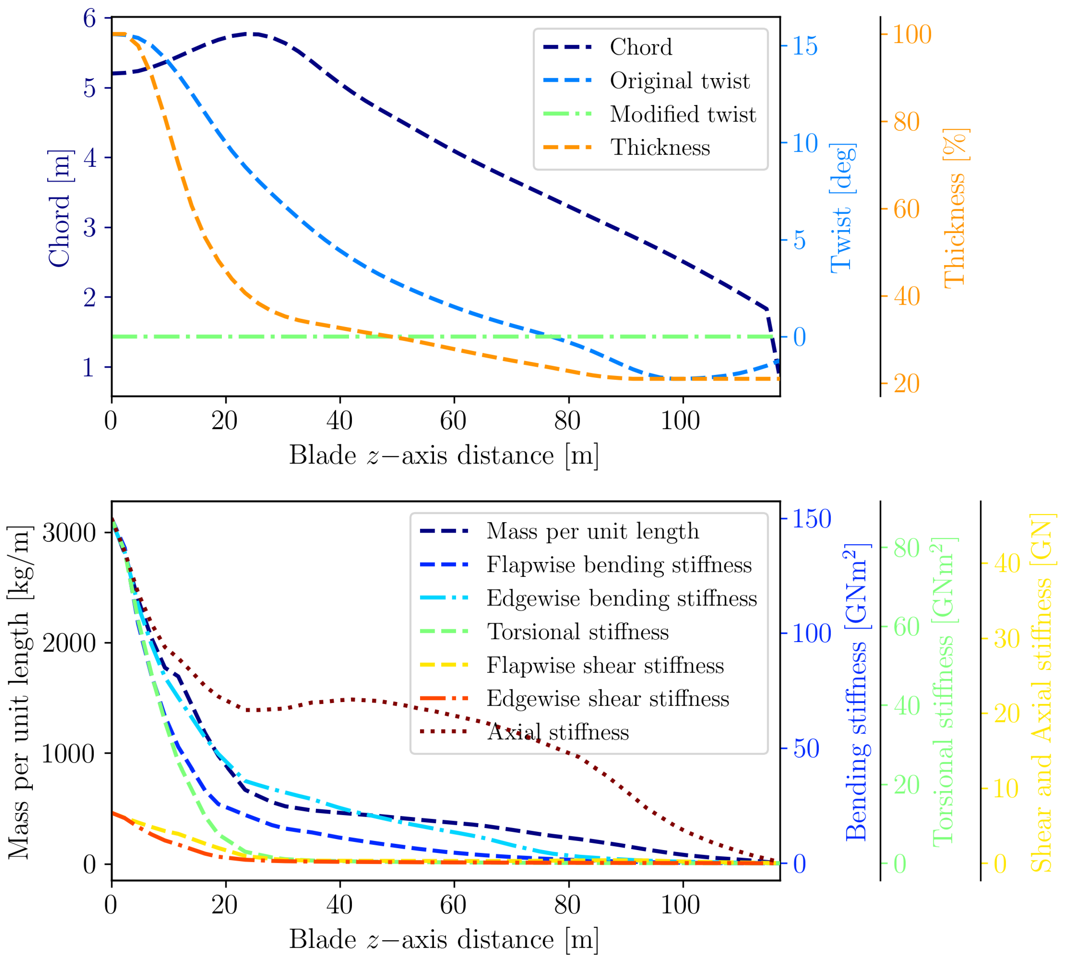
Figure 2. The chord distribution of the IEA 15 MW reference wind turbine is applied without change, but twist distribution is modified to zero (untwisted blade) to simplify the problem of interest. However, it is understandable that this is not realistic for real wind turbine blades. Therefore, the influence of twist distribution will be given in Section 6. The structural properties like mass, bending stiffness, shear stiffness, torsional stiffness and axial stiffness distributions are adopted without any change. This includes the shear center distribution, neutral axis, principal axis orientation and mass axis orientation, but these parameters are not shown in this paper for conciseness.
2.3. Description of the Test Cases
In the present studies, the test case is limited only to cover the blade characteristics to simplify the physical interactions and also to enable isolation of the blade excitation effects. Therefore, tower and all other structures are set to rigid and only one blade is modeled. The blade is parked at an azimuth angle of zero (blade pointing up) with the blade being pitched to 71.45
∘, which effectively creates a mean angle of attack of 18.55
∘ with the wind coming from upstream. This mean angle of attack is chosen to match the experimental data for a pitching airfoil case defined in [
32]. The rotational speed of the rotor is set to zero to simulate the turbine condition in parked operation. The calculation for the momentum theory is no longer relevant for this case, therefore the induction calculations and the associated engineering sub-models like tip loss correction and dynamic wake are switched off. However, dynamic stall effects are included since they are highly relevant for the case. In the present studies, three dynamic stall models are tested: ye, BL and IAG models. The blade is exposed to sinusoidal variation of the wind velocity in the following form:
where
Here,
represents the excitation amplitude and is set to be constant at 10.45
∘, which again corresponds to the experimental data for a pitching airfoil case defined in [
32]. The values of the incoming wind speed
and excitation frequency
f are varied from 10 m/s - 50 m/s and 0.086 Hz - 1.03 Hz, respectively. Depending on the test cases being investigated, it is often more convenient to represent the frequency in non-dimensional form. In the studies, this is done either in form of the reduced frequency:
or as a ratio to the natural frequency. All simulations are performed for 100 s with a timestep size of 0.02 s.
Since the studies are focused on the edgewise resonance, it is a logical choice to use the natural frequency of the blade edgewise mode (
). For this purpose, a modal analysis was performed in Bladed which yields the modes listed in
Table 1. It can be seen that the 1st edgewise modal frequency is about 0.687 Hz. This means that the frequencies being evaluated (0.086 Hz - 1.03 Hz) will be within the range of 0.125
to 1.5
.
3. Comparison of Dynamic Stall Model against Pitching Airfoil Data
To verify the accuracy of dynamic stall models, Bladed calculations are compared with experimental data of a pitching S809 airfoil. This is done specifically at the blade station located at 93.68 m. Since the pitching airfoil data obtained from Ref. [
32] does not include flexibility (measured on rigid airfoil in a wind tunnel), flexibility setting for the blade is turned off in Bladed. Equation (1) and Equation (2) are applied through a Wind DLL module in Bladed with an angle of attack variation in Equation (3) being set such that the reduced frequency in Equation (4) at 93.68 m matches the measurement campaign. This effectively simulates a pitching airfoil case at
k = 0.079.
The results for all three force components - lift (
), drag (
) and pitching moment about a quarter chord (
) - are presented in
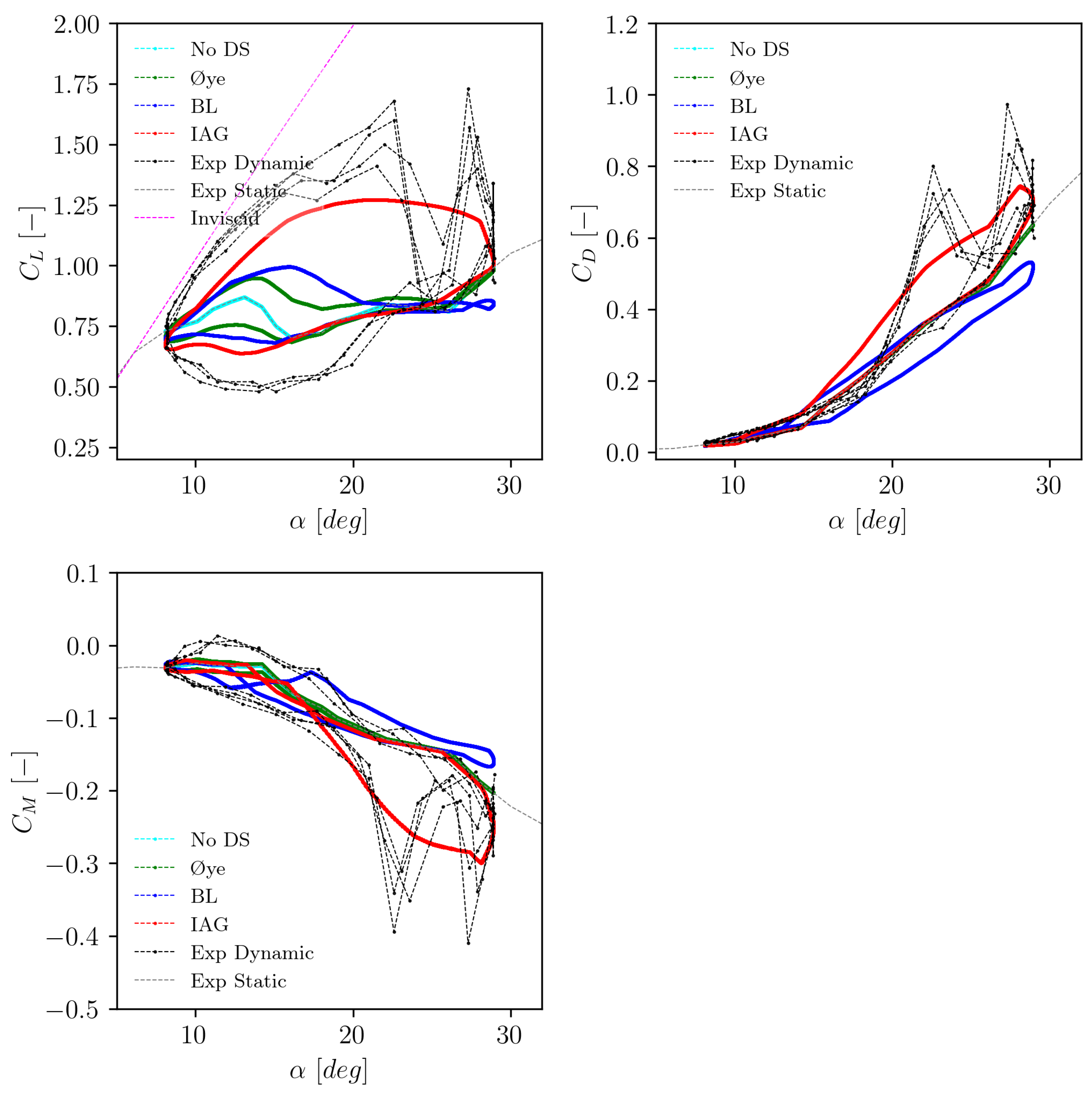
Figure 4. Both static and dynamic data sets obtained from experimental campaign are presented for comparison. It can be seen that the hysteresis effects of
,
and
are massively underestimated by the BL and Øye models. The IAG model clearly shows a better match with the experimental data at this deep stall situation. The improved prediction accuracy can be attributed to a more accurate estimation of the leading edge vortex effects in the IAG model [
9,
10].
4. Dynamic Responses of the Aerodynamic Coefficients
In Section 4.1 and Section 4.2, the effects of blade flexibility are taken into account. Here the dynamic characteristics of lift, drag and pitching moments are evaluated against two different conditions. First, the same reduced frequency as applied in Section 3 will be adopted in the discussion given in Section 4.1, but now with the blade flexibility being activated. Second, resultspolarresonance discusses the dynamic responses of the aerodynamic forces when the excitation frequency f is set to match the 1st edgewise modal frequency of the blade, see tabmodalfrequencies.
4.1. Exposed to a Constant Reduced Frequency
The simulations at a constant reduced frequency of
k = 0.079 (defined at 93.68 m blade station) are performed within
= [10,20,30,40,50] m/s. Here the magnitude of the wind speed becomes important on top of the excitation frequency because this drives the blade deflection. For the sake of conciseness, only the results for
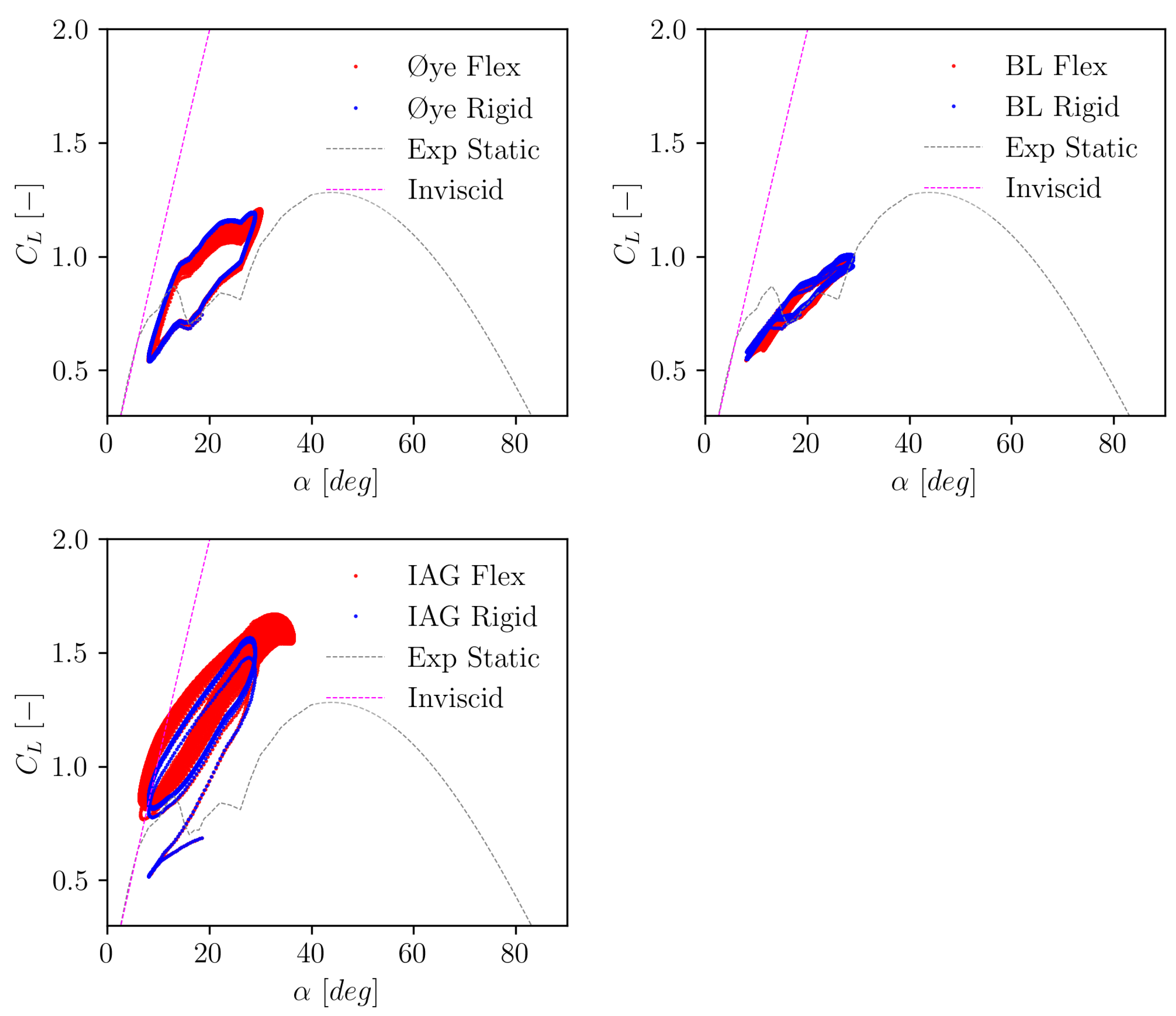
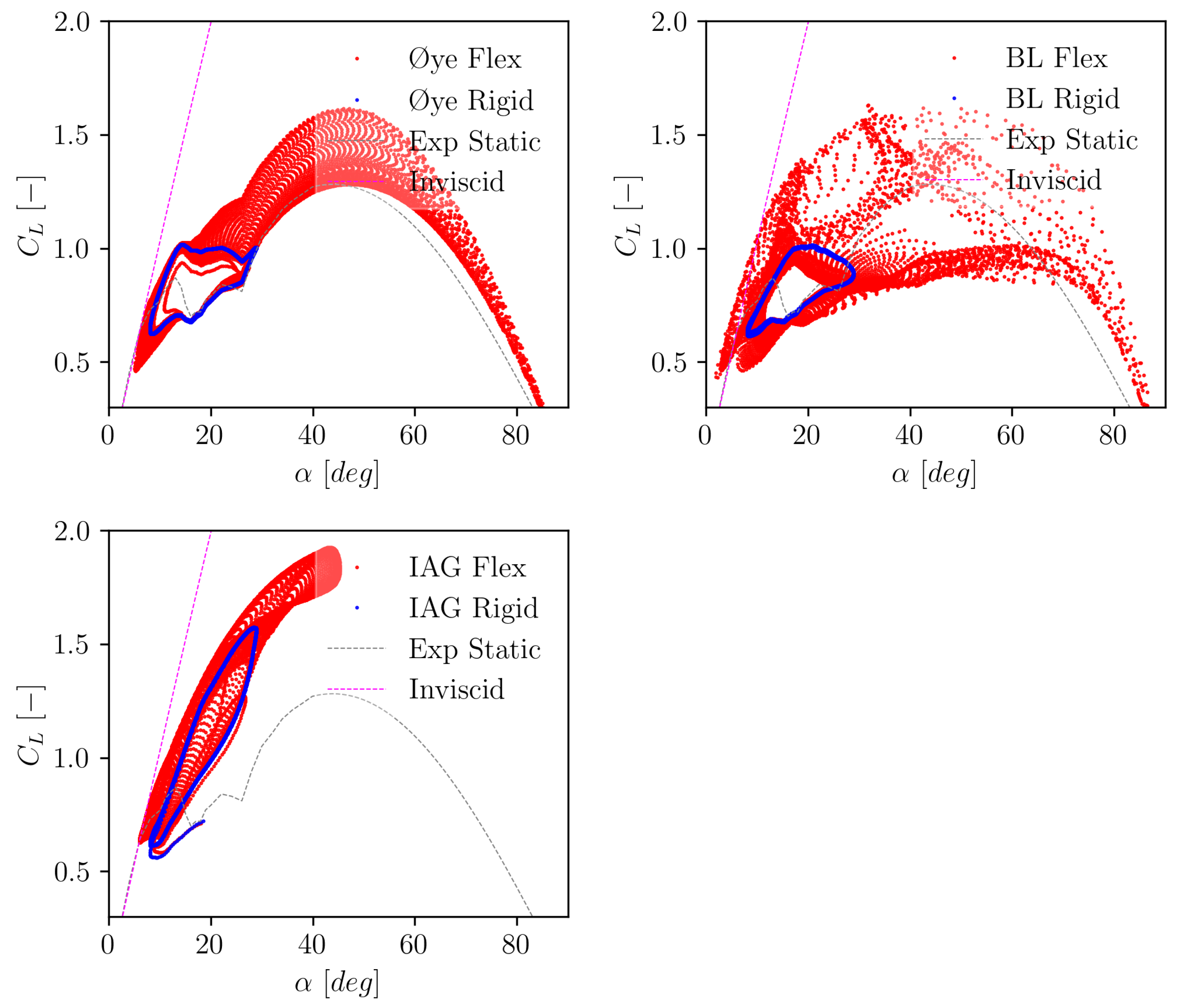
= 10 m/s, 30 m/s and 50 m/s for lift are presented in
Figure 5,
Figure 6 and
Figure 7, respectively. Results for different dynamic stall models for both rigid and flexible blades are presented. The complete plot for lift, drag and pitching moment are available in
Appendix B.1.
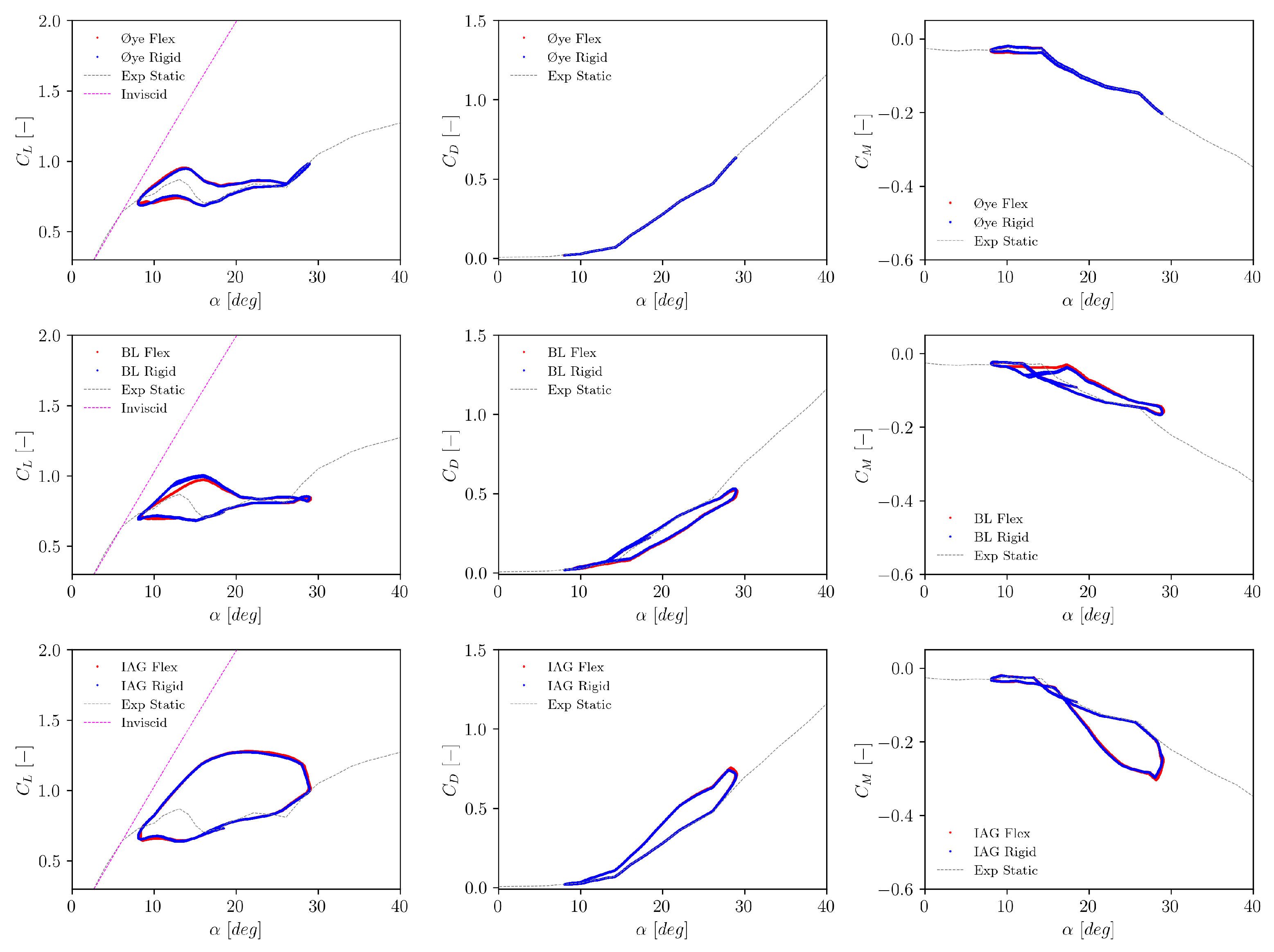
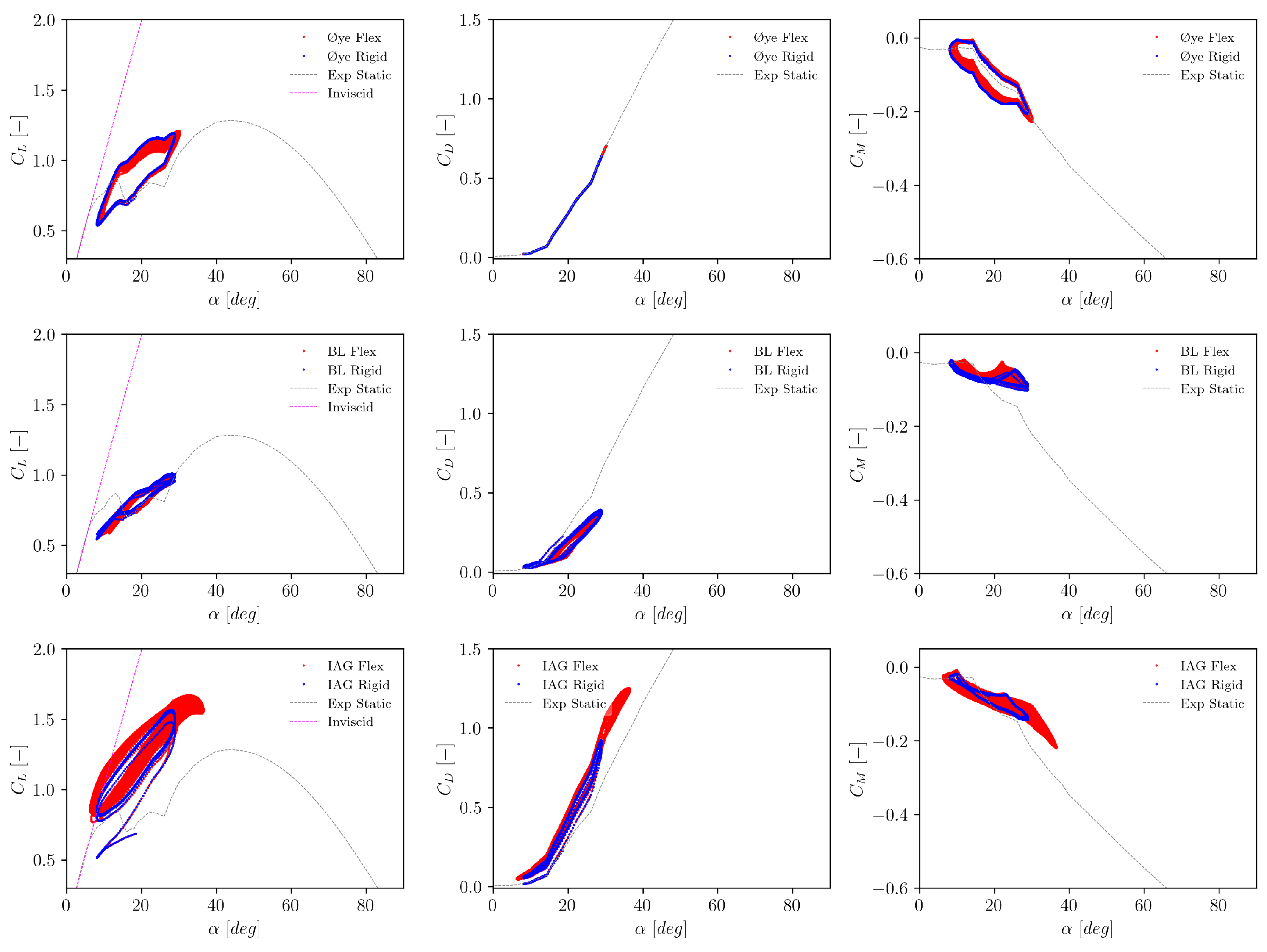
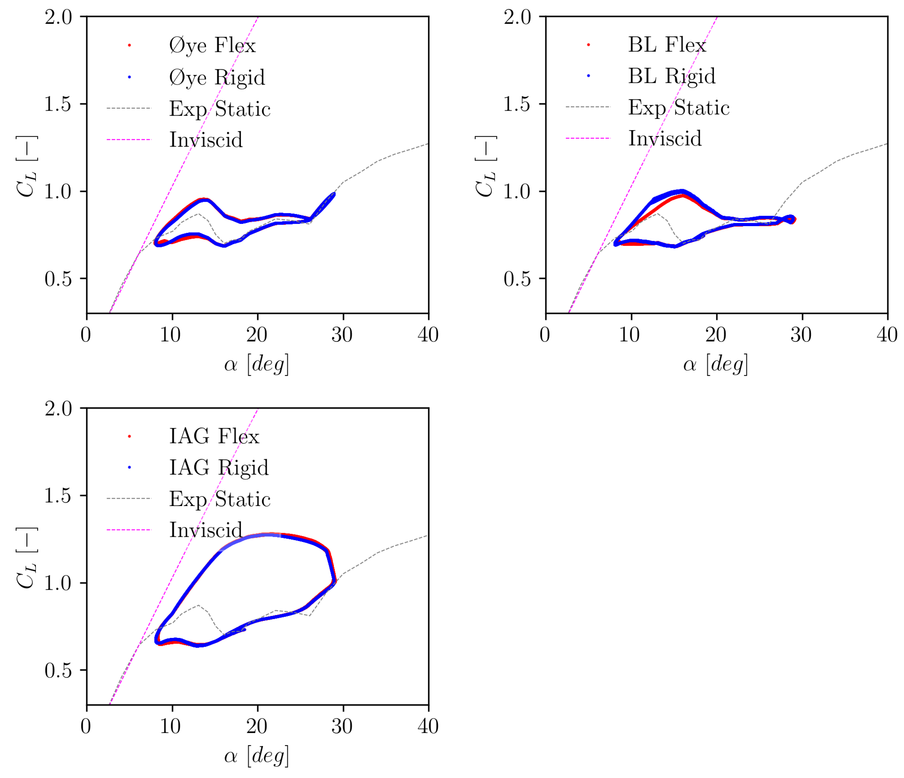
For the smallest wind speed of 10 m/s, it can be seen in
Figure 5 that blade flexibility has practically almost negligible influences. The difference between rigid and flexible settings remains small. Now, by increasing the wind speed to 30 m/s in
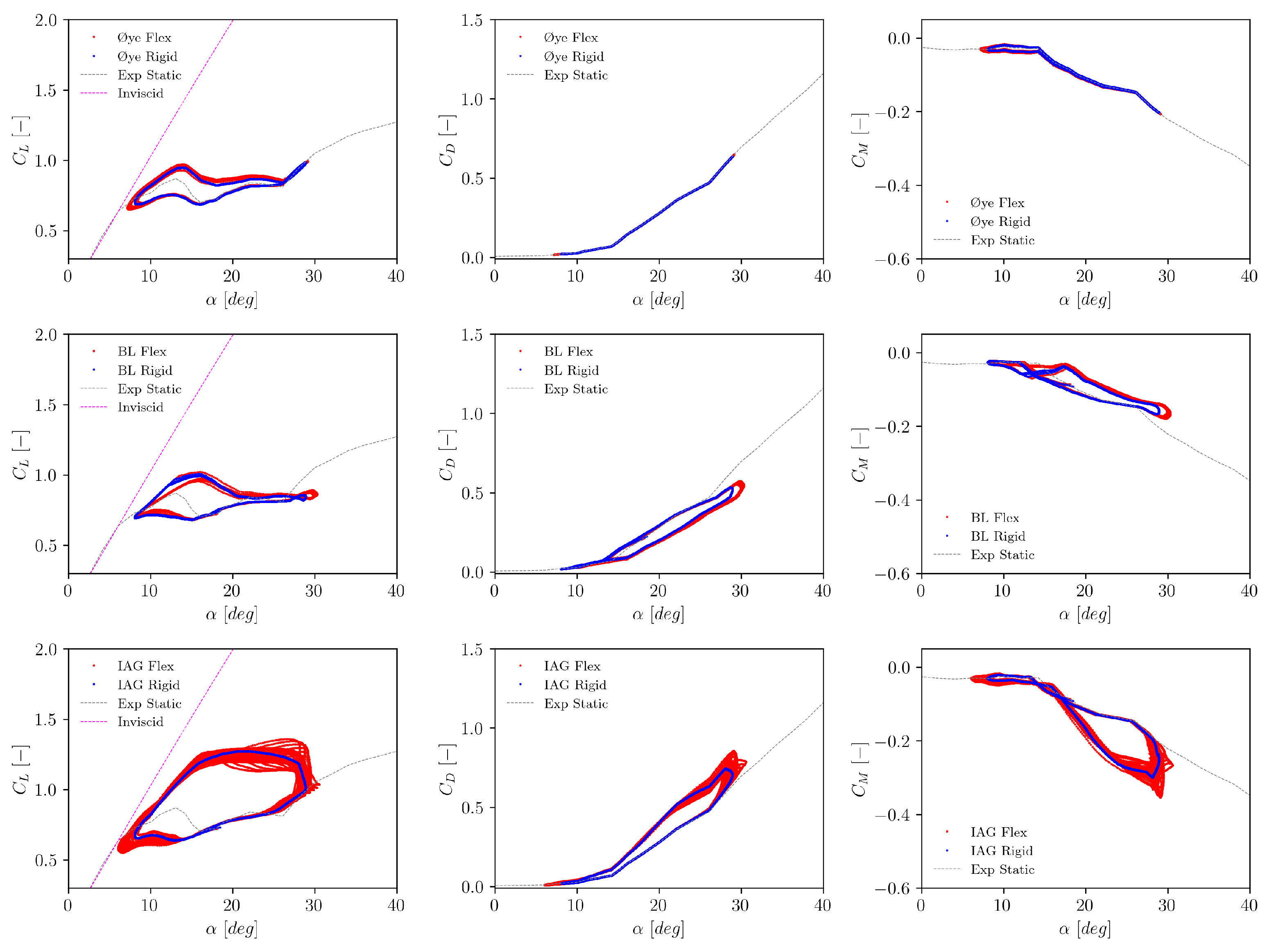
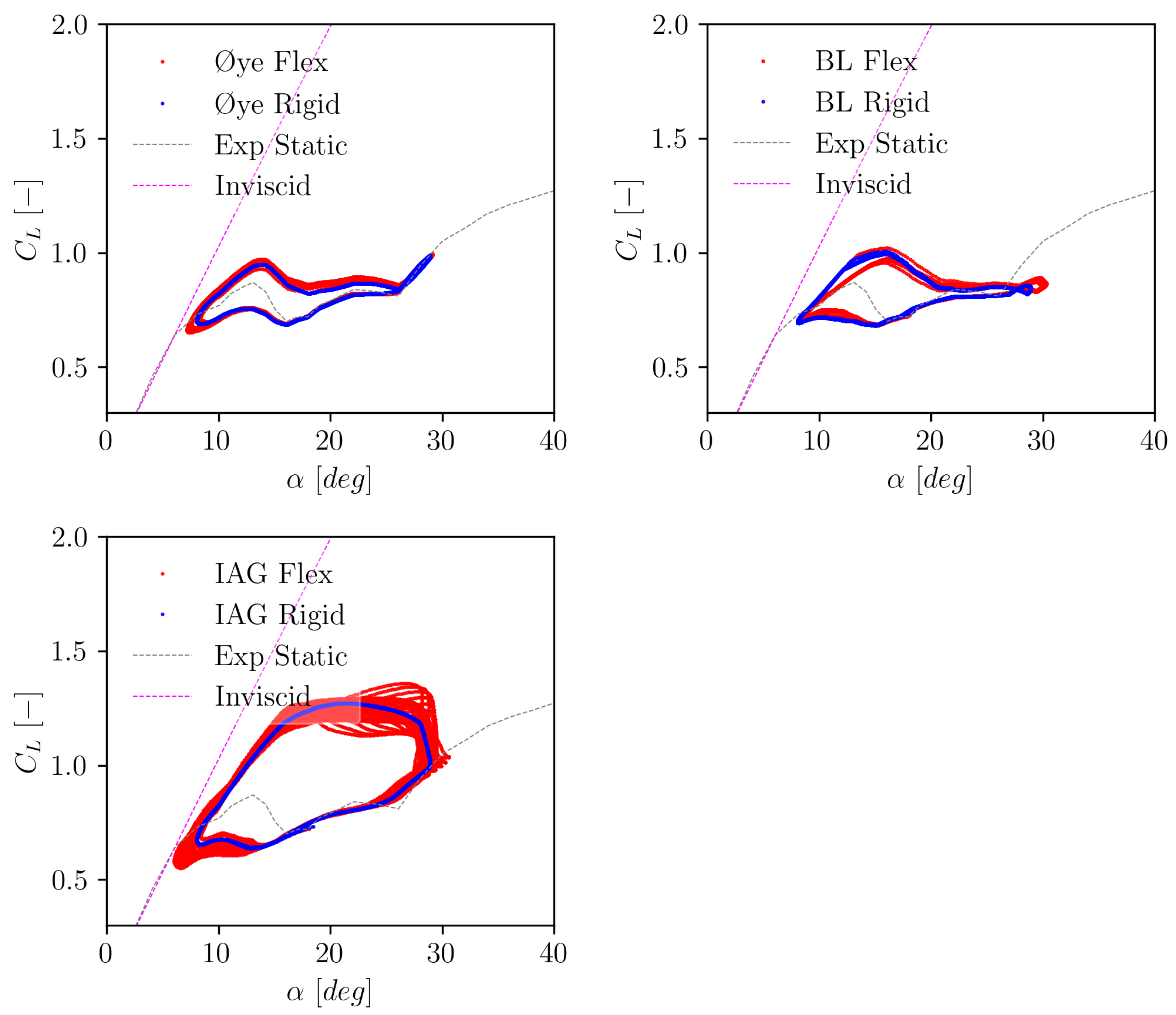
Figure 6, it can be seen that the results with flexible blade start to deviate from the rigid blade setting. This is particularly seen at upstroke regime (e.g., the higher lift part of the hysteresis). This behavior stems from the fact that the angle of attack increases within this part of the dynamic motion and dynamic solutions are more sensitive to engineering models being applied. The IAG model shows increased vibration characteristics compared to other models. Looking back at
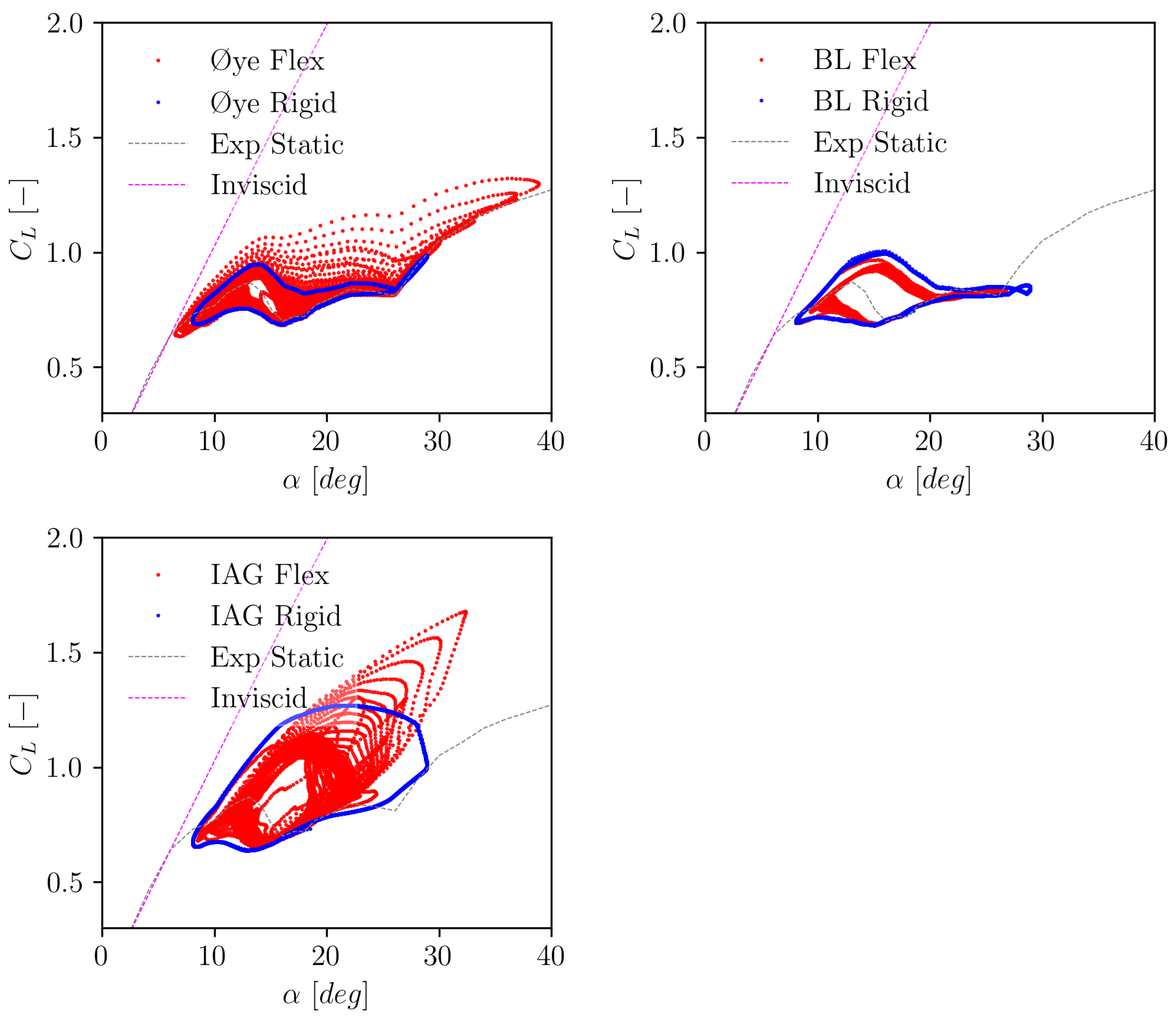
Figure 4, it seems that this is how the blade will likely react in reality (note that the same reduced frequency is simulated here).
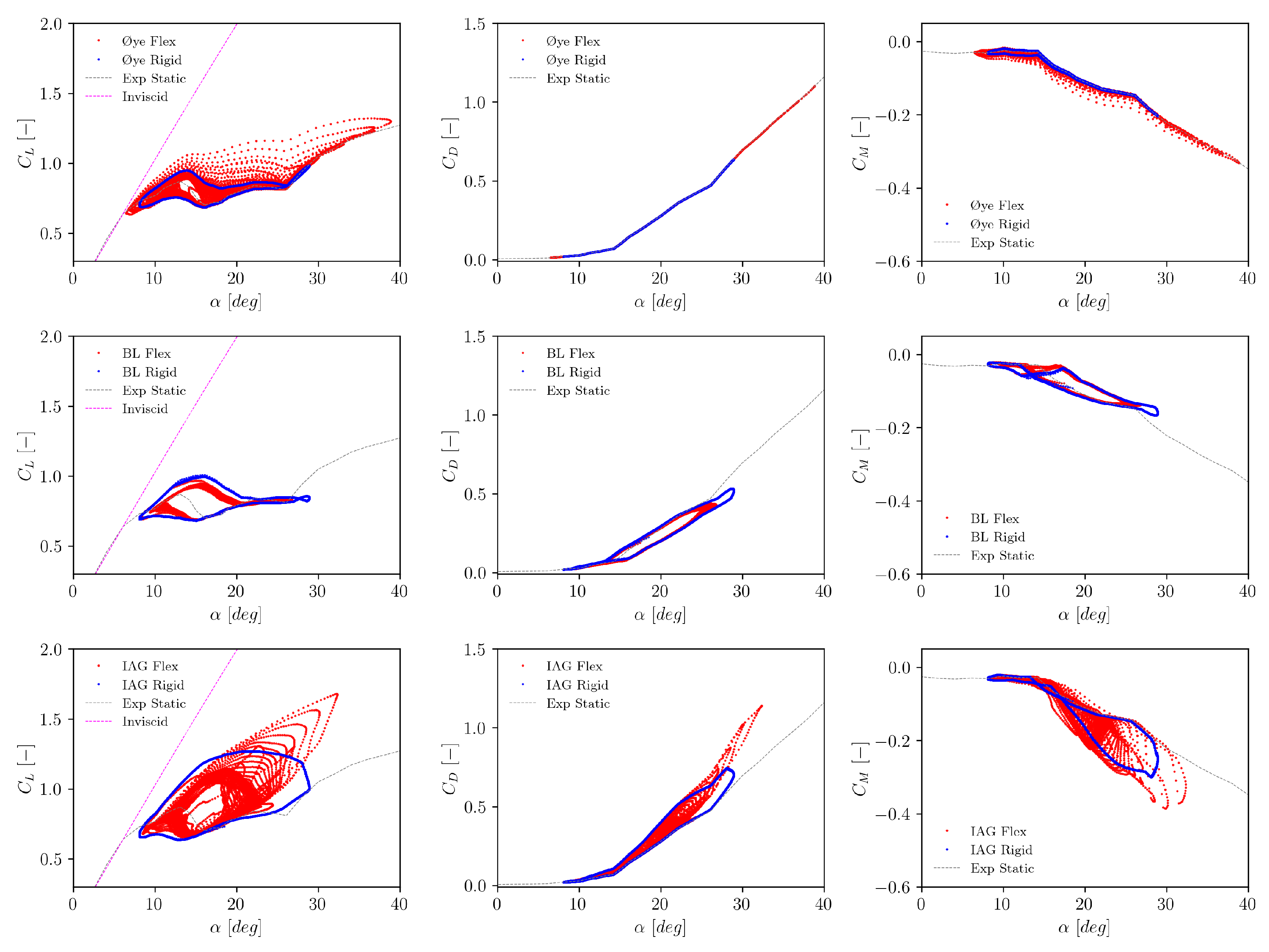
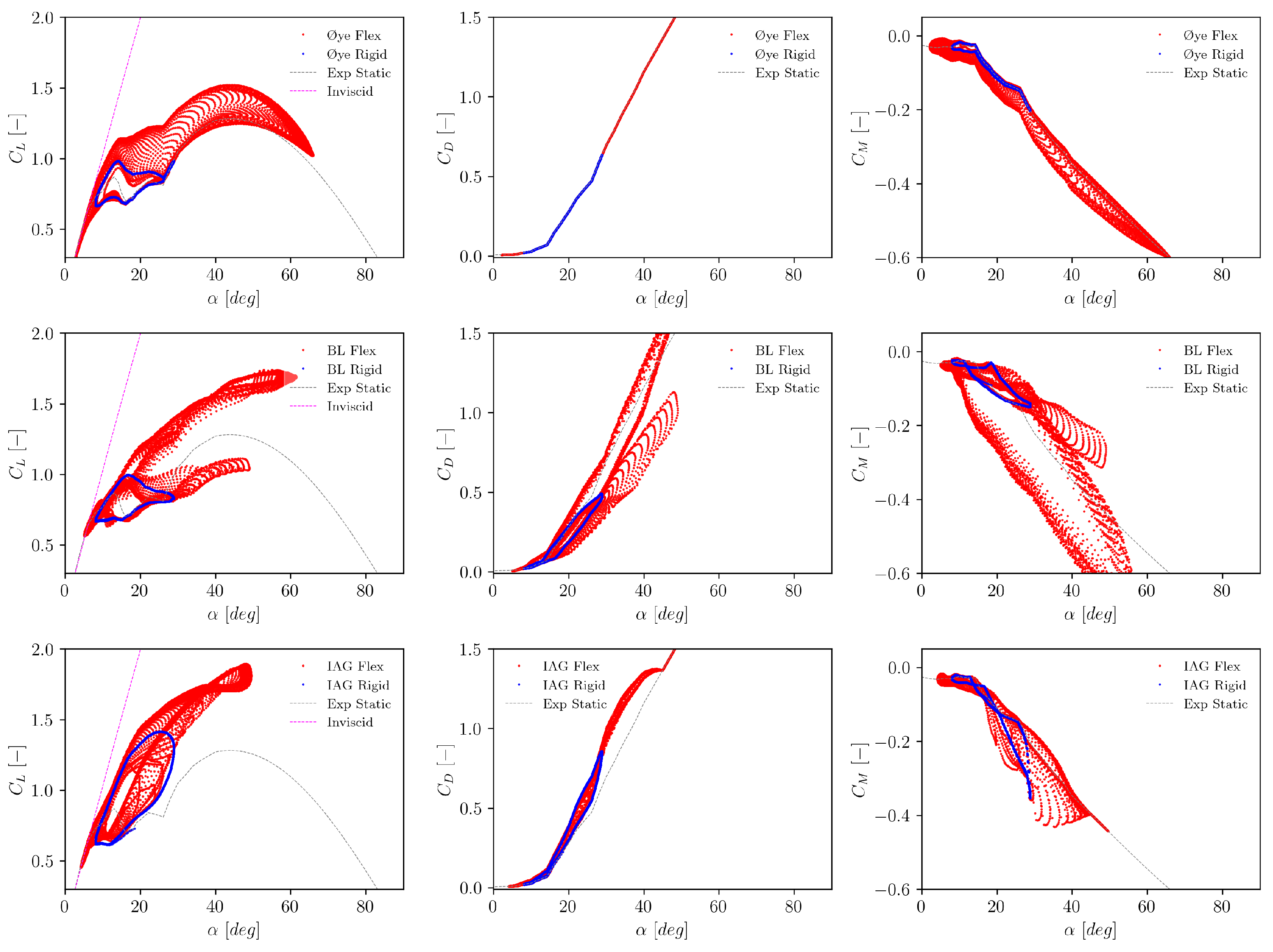
As for the highest evaluated wind speed of 50 m/s, results start to become much more radical as seen in
Figure 7. It can be seen that Øye model, BL model and IAG model behave fairly differently. The Øye model shows some increased variations of
in terms of the force magnitudes and the angle of attack range. In contrast to the Øye model, BL model shows somewhat reduced hysteresis curves. A similar behavior is also observed in the IAG model to some degree. However, since the vortex effects in the IAG model are more pronounced than the BL model, it can be seen that force fluctuations are actually increased locally at high angles of attack. The average dynamic polar gradient of the IAG model seems to increase, which might be attributed to the impulsive effects.
4.2. Exposed to Edgewise Resonance Frequency
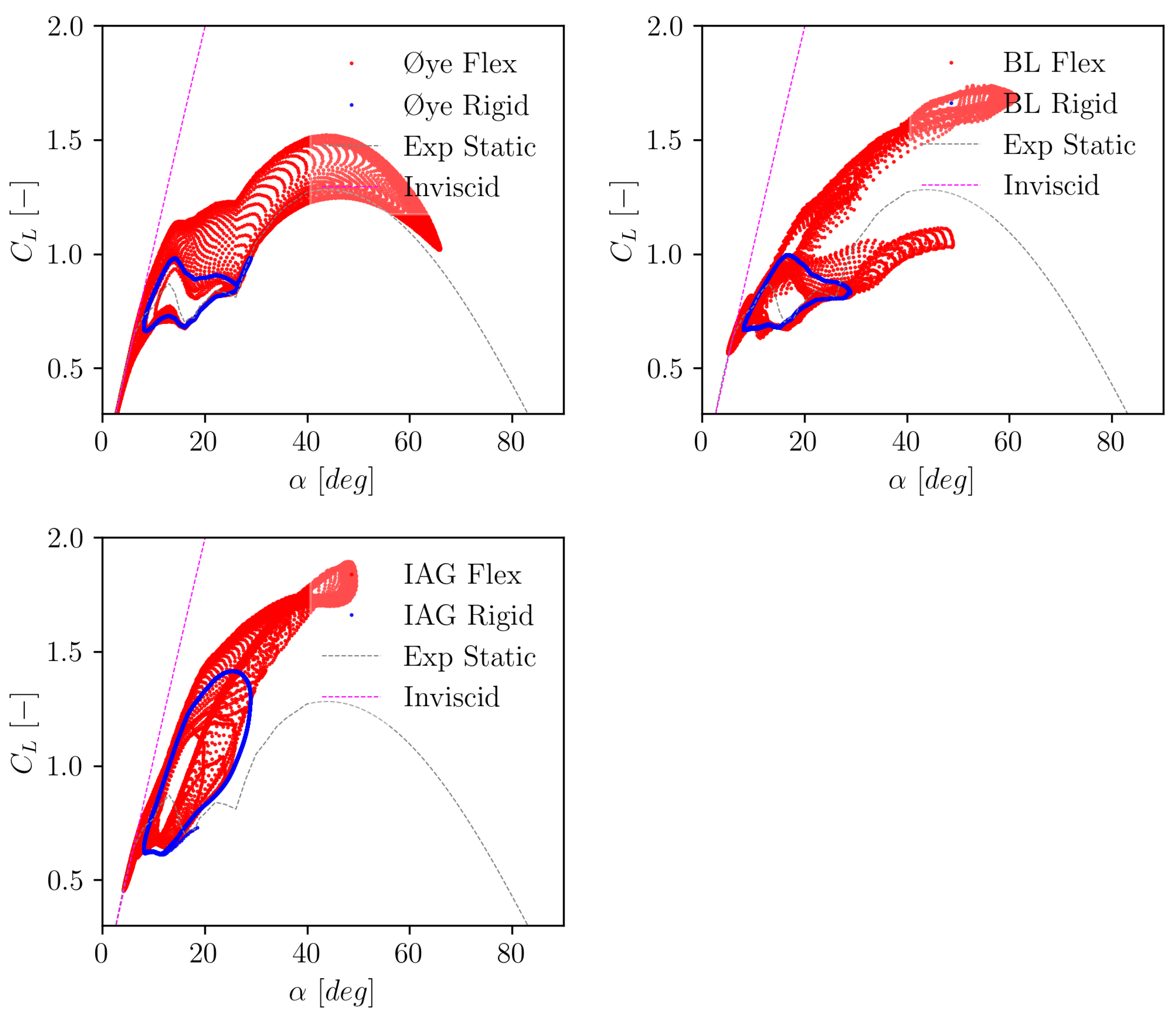
In this section, the blade is exposed to a constant frequency that matches the 1st edgewise modal frequency of the blade, which excites resonance. The simulations were done at varying wind speeds from 10 m/s - 50 m/s. This means that the reduced frequency itself decreases with the wind speed. Similar to the discussion in Section 4.1, only the results for
= 10 m/s, 30 m/s and 50 m/s for lift are presented for the sake of conciseness. The complete plot for lift, drag and pitching moment are available in
Appendix B.2.
In
Figure 8, the results for
= 10 m/ are presented for three different dynamic stall models. It shall be noted that this case has the highest reduced frequency of
k = 0.598, which in theory shall generate the strongest vibration. In contrast, the wind speed is the smallest (10 m/s) which limits the flexibility effects. It can be observed in
Figure 8 that the Øye model yields the weakest vibrations. The IAG model is characterized by the strongest hysteresis effects. This is mainly caused by the impulsive effects being dominant at high reduced frequency. On top of that, the blade flexibility, albeit at the relatively small wind speed, enhances the dynamic stall effects which yield in increased vibrations.
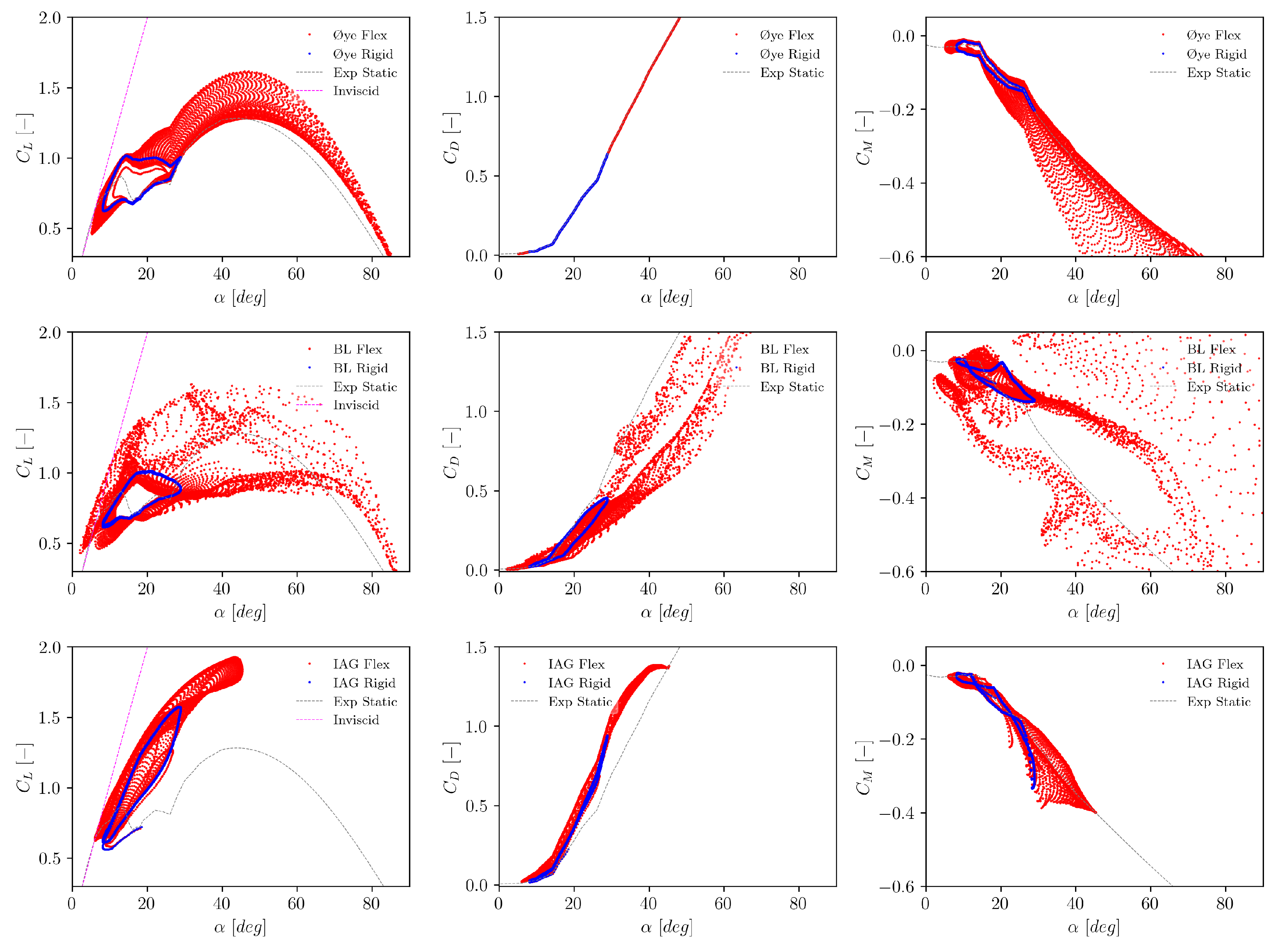
Increasing the wind speed to 30 m/s yields a drastic change of the vibration characteristics. This test case has a reduced frequency of about 0.199 that is still considerably high. On top of that, blade flexibility effects start to become stronger. It can be seen that the vibrations in the Øye model are amplified massively, which occurs mainly only during the vortex breakdown phase, see that the discrepancies of the rigid with the flexible case occur mainly starting from = 18∘. The BL model is severely affected by the resonance effects throughout all considered excitation range. It can be seen that varies violently from the lowest to the highest angle of attack. The IAG model, on the other hand, shows somewhat a more stabilized vibration behavior and the gradient of the dynamic polar is larger than the other models. At this reduced frequency, it is expected that the strength of the impulsive and circulatory effects is fairly comparable.
For the highest considered wind speed of 50 m/s, the vibrations from the ye and BL models are now stabilized to a smaller level than the 30 m/s case. This comes from the fact that the actual reduced frequency is smaller than the 30 m/s case to the 50 m/s case. The vibration characteristics for the IAG model is fairly comparable with the 30 m/s case. For this flow condition, the circulatory effects are getting stronger while the impulsive effects are becoming smaller.
Figure 8.
Dynamic lift polar calculated at a constant resonance frequency of f = 0.687 Hz at 10 m/s (at k = 0.598).
Figure 8.
Dynamic lift polar calculated at a constant resonance frequency of f = 0.687 Hz at 10 m/s (at k = 0.598).
Figure 9.
Dynamic lift polar calculated at a constant resonance frequency of f = 0.687 Hz at 30 m/s (at k = 0.199).
Figure 9.
Dynamic lift polar calculated at a constant resonance frequency of f = 0.687 Hz at 30 m/s (at k = 0.199).
Figure 10.
Dynamic lift polar calculated at a constant resonance frequency of f = 0.687 Hz at 50 m/s (at k = 0.12).
Figure 10.
Dynamic lift polar calculated at a constant resonance frequency of f = 0.687 Hz at 50 m/s (at k = 0.12).
5. Angle of Attack Range Variations
In this section, the range of the angle of attack change from the flexible blade simulation to the rigid blade simulation is compared. This is formulated as:
which highlights how much blade vibration grows over the time. Similar with the discussion in Section 4, two cases are considered: first, at the same reduced frequency as applied in Section 3. For the second case, the excitation frequency is varied from low to high frequency levels within
.
5.1. Exposed to a Constant Reduced Frequency
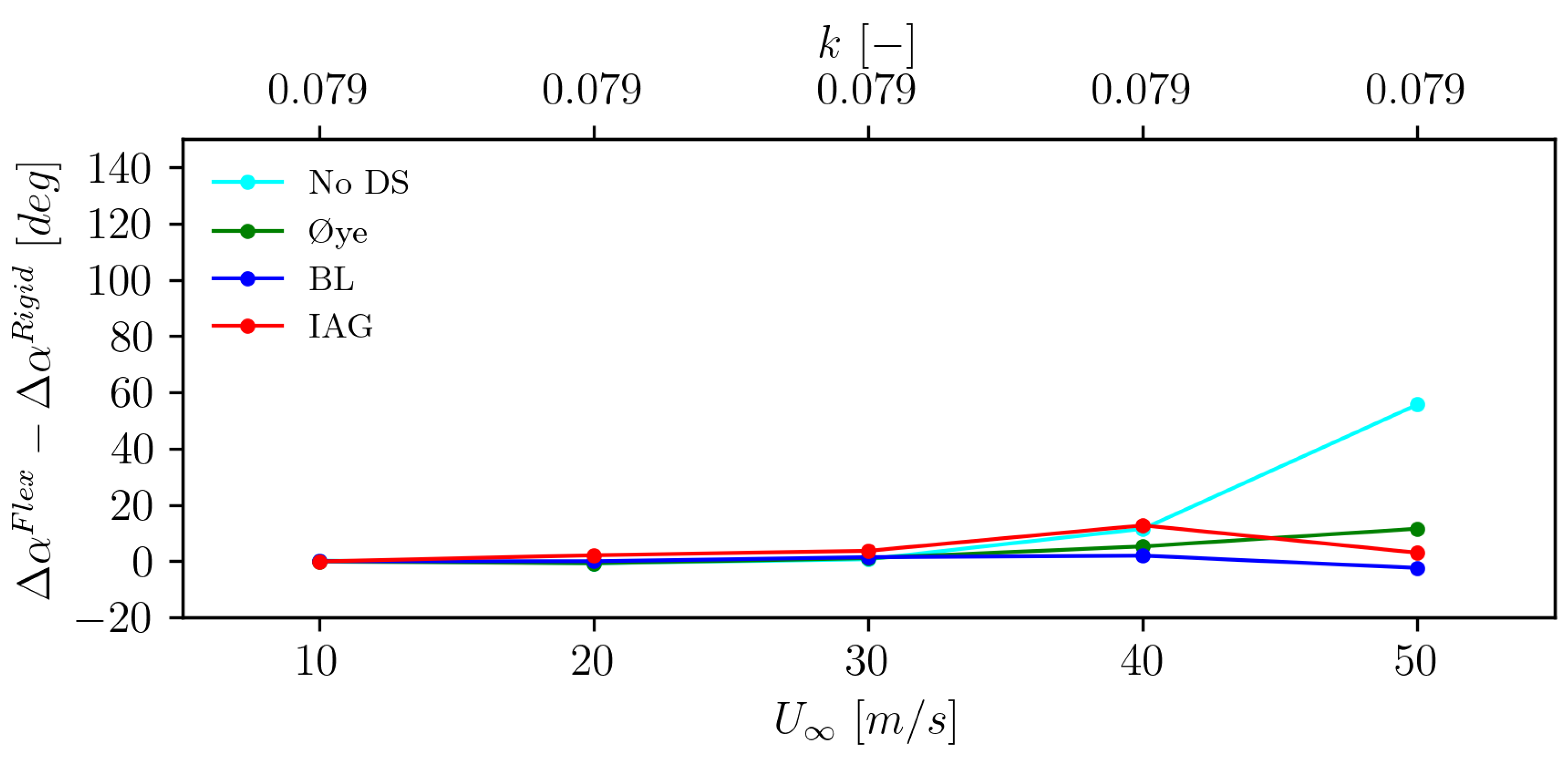
Figure 11 displays the vibration growth for the case at a constant reduced frequency of
k = 0.079 (calculated at 93.68 m of the blade length). It can be seen that the range of the angle of attack is not altered too significantly for the low wind speed case up to 30 m/s. A larger difference between the rigid case and the flexible case starts to occur starting from the wind speed of 40 m/s. It can also be observed that the IAG dynamic stall model has the largest increase of the range up to 40 m/s, before it decreases at the wind speed of 50 m/s. On the other hand, the BL model consistently shows the smallest level of range change across all wind speeds. It is also notable that the case without dynamic stall model shows a consistent increase of the range with increasing wind speed.
5.2. Exposed to Varying Frequencies
The aeroelastic responses of the blade section at varying frequencies are discussed in the present section. To enable a clear comparison about the relative relationship between the excitation frequency (
f) with the 1st edgewise natural frequency (
), the excitation frequency is reported as the normalized frequency (
), and this ranges from 0.125 to 1.5. To enable a comprehensive evaluations of the aeroelastic response, the results are plotted in two different ways:
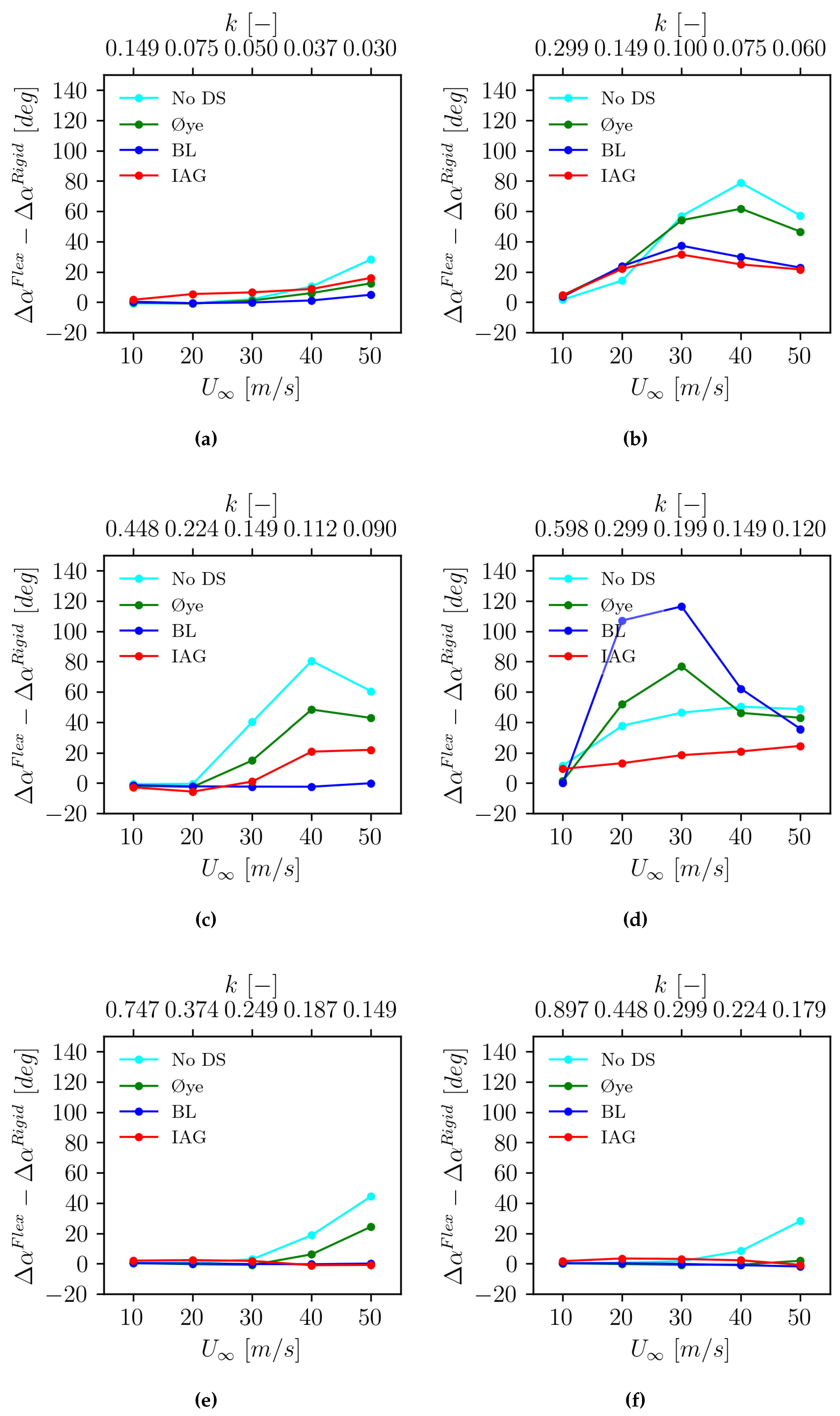
Figure 12 groups the plots based on the excitation frequency and the data are plotted with respect to the wind speed, meanwhile in
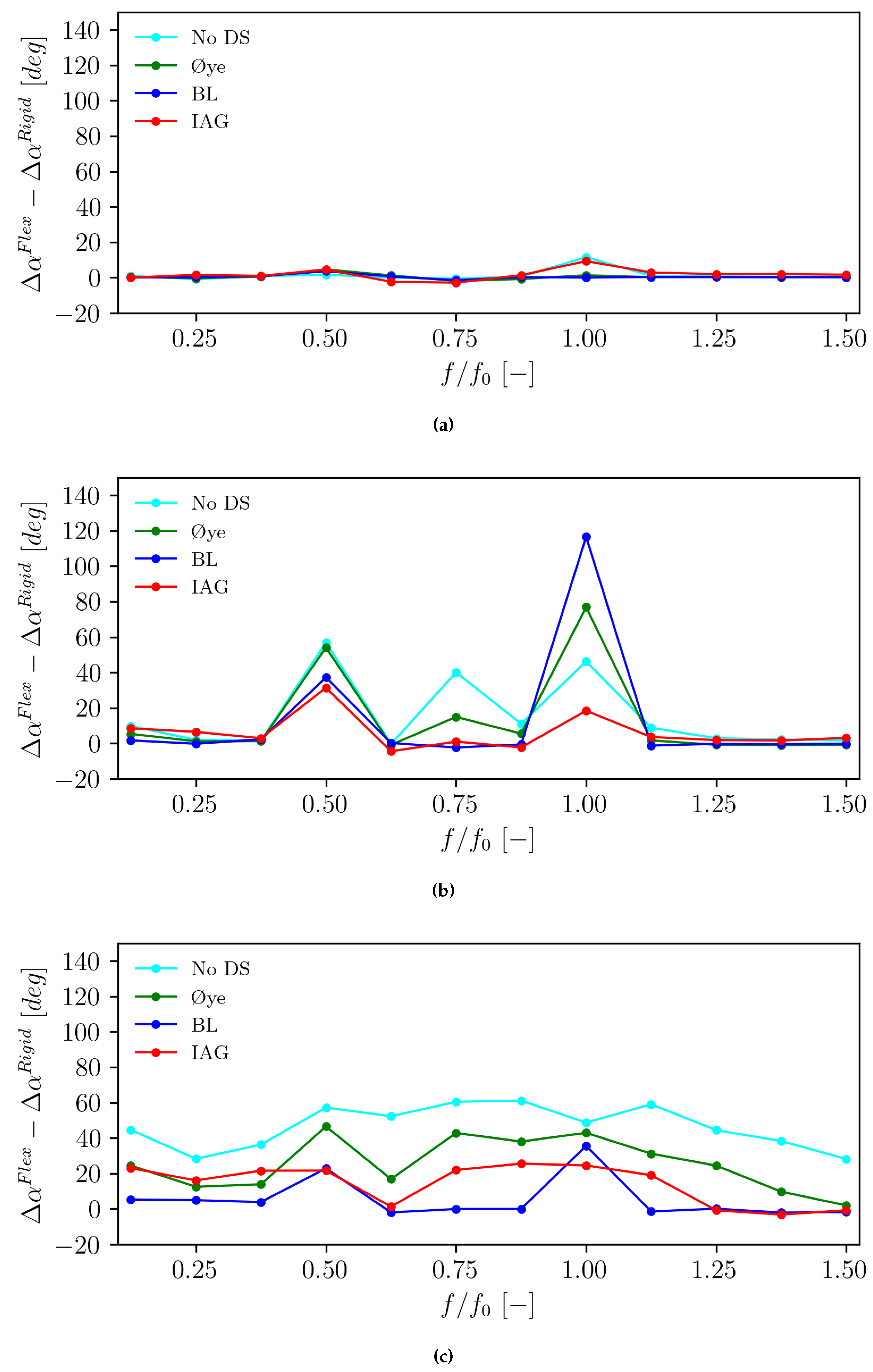
Figure 13 the results are grouped based on the wind speed and the relationship is plotted against the excitation frequency itself.
Figure 12 clearly illustrates how the reduced frequency affects the vibration characteristics of the blade. Note that the same excitation frequency yields a different reduced frequency (
k) for a different wind speed. At the excitation frequency level
of 0.25 in
Figure 12a, one can see that the IAG model generally shows the largest deviation compared to the rigid blade case before it is overtaken by the no dynamic stall case at 50 m/s. Here it can be seen that the BL model case generally shows the lowest deviation compared to the rigid case. By increasing the excitation frequency to half of the 1st edgewise natural frequency (
= 0.25) in
Figure 12b, the IAG model now shows the lowest deviation against the rigid case, followed by the BL model, Øye model and no dynamic stall model cases. This observation is mostly pronounced with increasing wind speed up to 40 m/s, before it decreases again when reaching 50 m/s case. The reason is associated with the reduction of the reduced frequency level becoming more significant than the blade flexibility effect itself.
A similar story is found at the non-dimensional excitation frequency of 0.75 in
Figure 12c, where the discrepancy against the rigid case increases up to a certain wind speed. Here it is also observed that while all other cases generally show an increased level of discrepancy against the rigid blade case, the BL model is largely not affected by this particular frequency. Having observed the magnitude of the frequency in more detail, the applied frequency is actually close to the 1st flapwise natural frequency of the blade. Therefore, the flapwise mode is actually what is being excited.
Now looking closer at the actual resonance frequency of the 1st edgewise mode in
Figure 12d, the IAG model shows the least deviation compared to the rigid blade case and is followed by no dynamic stall, Øye model and the BL model cases. This frequency excitation is considered the most challenging case because generally the edgewise mode is prone to negative damping and aeroelastic codes tend to underestimate the aerodynamic damping. The IAG model clearly shows an increased damping level under this condition.
Further increasing the excitation frequency in
Figure 12e and
Figure 12f, it can be seen that generally the results between the rigid and flexible cases do not deviate too much. This shows that the effects of resonance is not prominent and the blade remains in its stable conditions.
Figure 13 is aimed specifically to assess the characteristics of the dynamic stall model on the aeroelastic response for varying frequencies. At the smallest wind speed case of 10 m/s in
Figure 13a, the excitation frequency largely has no impact on the range of angle of attack. The range only slightly increases for the no dynamic stall case and the IAG model case at the edgewise resonance frequency. By increasing the wind speed to 30 m/s, the blade flexibility plays a stronger role in the aeroelastic characteristics as shown in
Figure 13b. It can be clearly observed that the excitation occurs at
= 0.5 and
= 1.0 due to the edgewise excitation while at
= 0.75 due to flapwise excitation. For the BL model and Øye model cases, the blade section is excited strongly at the resonance frequency and this leads to the angle of attack variation to grow significantly.
Further increasing the wind speed to 50 m/s in
Figure 13c, it is notable that most cases deviate from the rigid blade case for all frequency ranges, except for the BL model. However, it is clearly observed that the deviation is smaller than the one observed in
Figure 13b. The explanation lies in the fact that the blade flexibility effects are prominent for this wind speed case, but the excitation reduced frequency itself is actually smaller than the the case with a wind speed of 30 m/s. This is also supported by the discussion made in
Figure 12d.
6. Twist Angle Distribution Influence
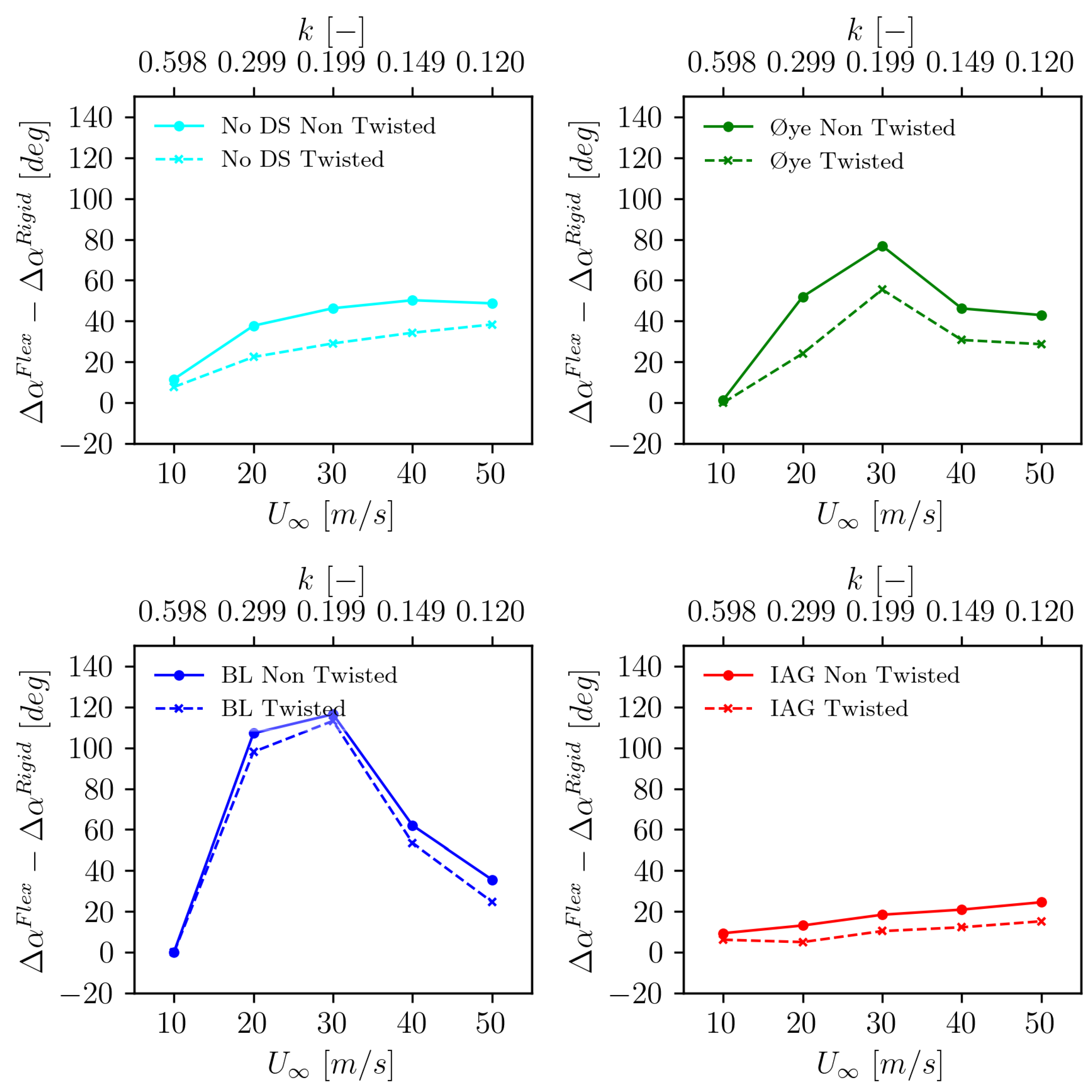
It has been discussed above that dynamic stall model plays a significant role in the aeroelastic effects depending on the excitation frequency. Now, to gain deeper insights into design considerations, it is interesting to see if twist angles affect the characteristics. Therefore, the original twist angle distribution in
Figure 3 is now applied. First of all, to evaluate how much twist angle changes the modal properties (keeping all other structural constraints the same), modal analysis of the blade is carried out and listed in
Table 2. It can be seen that the modal frequencies are altered slightly, but not to a significant degree. The same inflow conditions are then imposed, but the blade set angle is adjusted to maintain the same angle of attack range at
r = 93.68 m for the rigid blade case in comparison with the untwisted blade.
The aeroelastic response of the blade is presented in
Figure 14 for different dynamic stall modeling approaches. For all cases, it can be seen that the addition of twist reduces the growth of the angle of attack range when the blade flexibility is considered. The effects are mostly prominent for the no dynamic stall case and the case employing the Øye model. This is followed by the IAG model and the weakest effect is observed for the BL model. The twist distribution changes the acting angle of attack and pushes the operating range further away from the stall. The twist angle distribution will likely become an important aspect to enhance large wind turbine blade stability during parked or idling conditions.
7. Conclusions and Outlook
The present studies have been conducted to evaluate the sensitivity of different dynamic stall models to edgewise vibrations occurring on large-flexible wind turbine blades. The investigations were done systematically by starting from the rigid response of the blade section with respect to an oscillating wind conditions. The flexibility of the blade is then applied, causing a dynamic response of the angle of attack. From the discussions, the following aspects can be summarized:
It is clear that dynamic stall model plays a strong role in the aeroelastic characteristics. The angle of attack range starts to grow away from the rigid blade case when the excitation frequency is between . It is observed that in between this range, the flapwise mode is one souce of the excitation, though the strongest cause is related to the edgewise mode at = 0.5 and = 1.0. This can be used as a rough guidance when performing wind turbine design and running load cases especially in idling or parked conditions.
The IAG model shows the best agreement with the pitching airfoil data, which represents the rigid conditions. Under the influence of blade flexibility, the IAG model is most sensitive to frequency excitation far from the edgewise resonance. However, when the excitation is close to the edgewise resonance frequency, the IAG model shows a higher aerodynamic damping which increases the blade stability. This explains the characteristics of this model in generating lower loads for the certain idling cases as discussed in [
13,
17].
The characteristics of the IAG model for different excitation frequencies are also dependent upon the impulsive contributions. A higher reduced frequency typically increases the impulsive terms.
Twist distribution is crucial in determining the aeroelastic stability of the blade. Adding a twist distribution (assuming all structural properties the same) only slightly alters the blade modal frequencies, but affects the operating range of the angle of attack.
Future studies might be aimed at investigating the dynamic stall sensitivity at higher excitation frequency levels to gain a better picture of the higher harmonic effects. Furthermore, incorporating the torsional effects will also be important to evaluate the coupling between the edgewise and torsional terms and how the aerodynamic damping actually influences the aeroelastic characteristics.
Institutional Review Board Statement
Not applicable.
Informed Consent Statement
Not applicable.
Data Availability Statement
Data can be made available by contacting the corresponding author.
Conflicts of Interest
The author declares that the research was conducted in the absence of any commercial or financial relationships that could be construed as a potential conflict of interest. It is declared that the author is an associate editor of Energies, at the time of submission. This has no impact on the peer review process and the final decision.
Appendix A. Modified Viterna 360° Extrapolation
The basic Viterna model is described by the following equations:
with
However, the Viterna approach does not taken into account the interpolation for pitching moment. Thus, in the present studies, the pitching moment is extrapolated by a simple hyperbolic function in the following form:
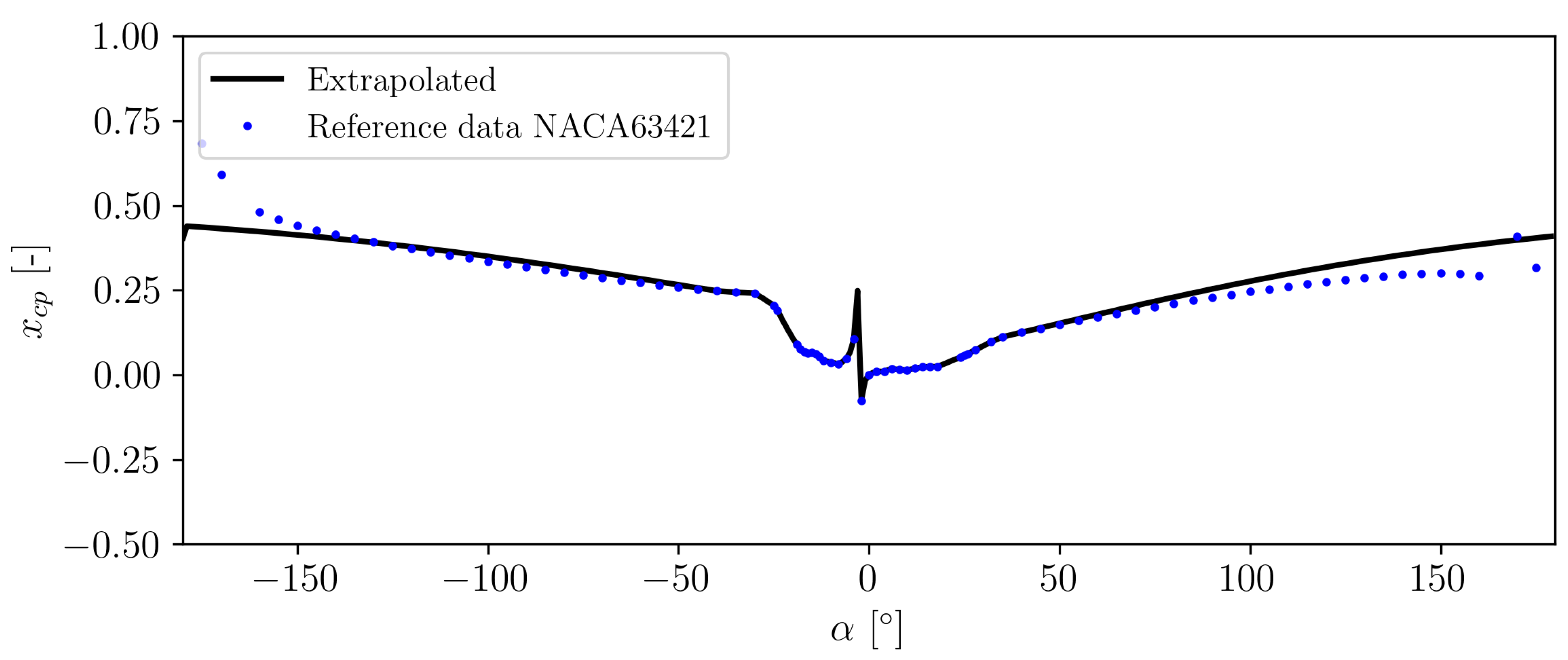
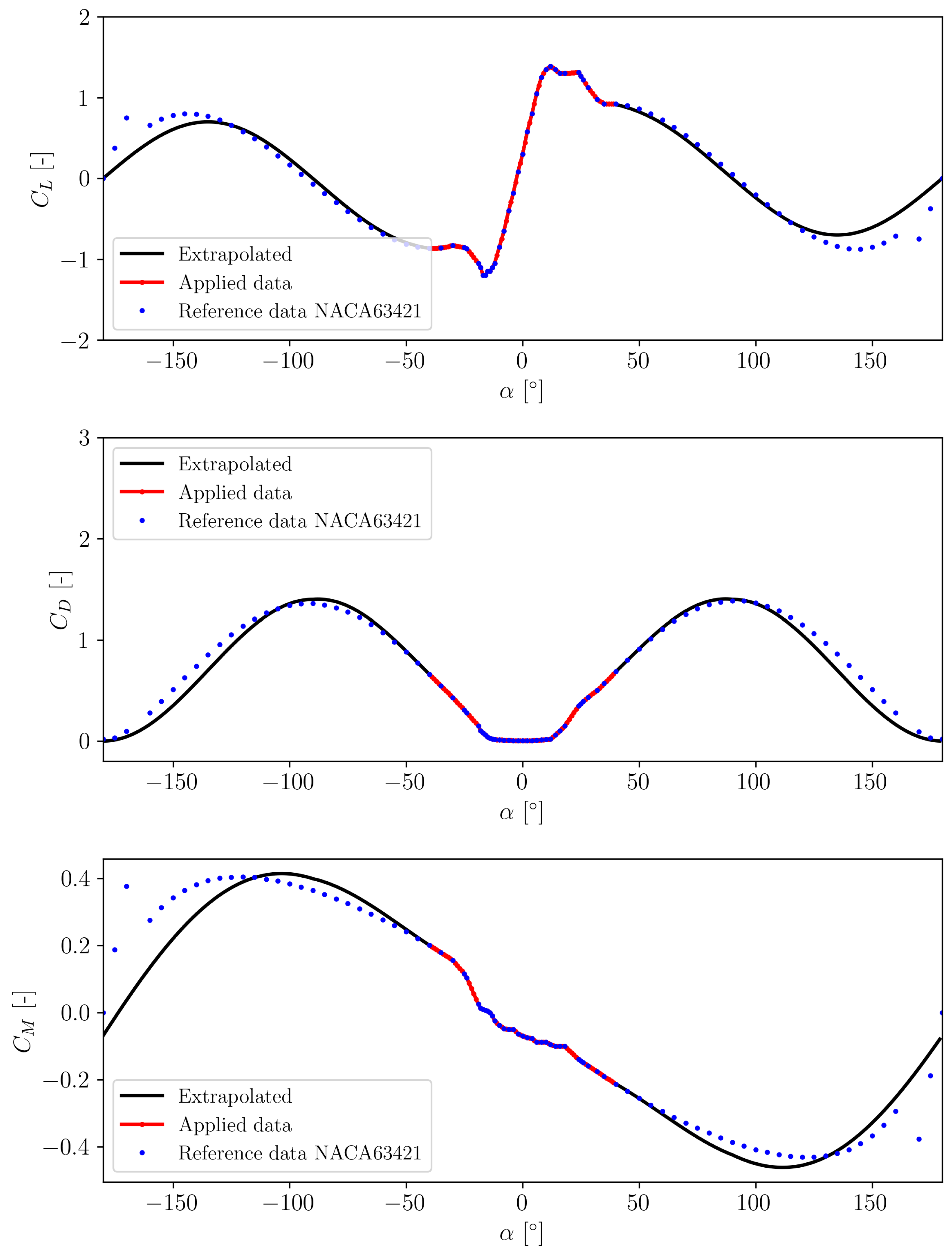
In the above pitching moment equations, represent the pitching moment at zero angle of attack ( = 0∘) while the superscript "end" denotes the values obtained at minimum or maximum of the available polar data set. Variable represents the movement of the center of pressure (normalized by chord) and is a parameter that defines a linear fraction of the angle of attack. defines the maximum location of the pressure center. It is known that moves toward the trailing edge location from the quarter chord when the angle of attack increases. It is assumed that the maximum location is achieved when the airfoil is oriented at , and this is assumed to occur at 25% of the chord measured from the trailing edge (0.5c from the quarter chord, ). Figure A1 illustrates the development of with the angle of attack increase.
Figure A1.
Illustration of movement when the angle of attack changes.
Figure A1.
Illustration of movement when the angle of attack changes.
Figure A2.
Comparison of between the extrapolated and reference data of the NACA 63421 airfoil.
Figure A2.
Comparison of between the extrapolated and reference data of the NACA 63421 airfoil.
In Figure A2, a comparison between the extrapolated value against a reference data for the NACA 63421 airfoil is presented. It can be seen that the general agreement with the reference data is acceptable within . When the angle of attack is increased further, discrepancy starts to occur but the general trend is captured relative well, except the reverse flow stall characteristics (when the trailing edge points toward the relative wind speed), see Figure A1. The comparison against the reference data for lift, drag and pitching moment is given in Figure A3. Similar with , the agreement is satisfactory, while discrepancy starts at a higher angle of attack when the reverse flow occurs.
Figure A3.
Comparison of the aerodynamic polar between the extrapolated and reference data of the NACA 63421 airfoil
Figure A3.
Comparison of the aerodynamic polar between the extrapolated and reference data of the NACA 63421 airfoil
Appendix B. Dynamic Polar Characteristics
Appendix B.1. Exposed to Constant Reduced Frequency
Figure A4.
Dynamic polar calculated at a constant reduced frequency of k = 0.079 at 10 m/s.
Figure A4.
Dynamic polar calculated at a constant reduced frequency of k = 0.079 at 10 m/s.
Figure A5.
Dynamic polar calculated at a constant reduced frequency of k = 0.079 at 30 m/s.
Figure A5.
Dynamic polar calculated at a constant reduced frequency of k = 0.079 at 30 m/s.
Figure A6.
Dynamic polar calculated at a constant reduced frequency of k = 0.079 at 50 m/s.
Figure A6.
Dynamic polar calculated at a constant reduced frequency of k = 0.079 at 50 m/s.
Appendix B.2. Exposed to Edgewise Resonance Frequency
Figure A7.
Dynamic polar calculated at a constant resonance frequency of f = 0.687 Hz at 10 m/s (at k = 0.598).
Figure A7.
Dynamic polar calculated at a constant resonance frequency of f = 0.687 Hz at 10 m/s (at k = 0.598).
Figure A8.
Dynamic polar calculated at a constant resonance frequency of f = 0.687 Hz at 30 m/s (at k = 0.199).
Figure A8.
Dynamic polar calculated at a constant resonance frequency of f = 0.687 Hz at 30 m/s (at k = 0.199).
Figure A9.
Dynamic polar calculated at a constant resonance frequency of f = 0.687 Hz at 50 m/s (at k = 0.12).
Figure A9.
Dynamic polar calculated at a constant resonance frequency of f = 0.687 Hz at 50 m/s (at k = 0.12).
References
- Bangga, G. Wind Turbine Aerodynamics Modeling Using CFD Approaches; AIP Publishing LLC, 2022.
- IEC. Wind energy generation systems-Part 1: Design requirements Ed. 4. In IEC Standard IEC-61400-1:2019; International Electrotechnical Commission, 2019.
- DNV. Loads and site conditions for wind turbines. In DNV Standard DNV-ST-0437; Det Norske Veritas, 2021.
- Leishman, J.G.; Beddoes, T. A Semi-Empirical model for dynamic stall. Journal of the American Helicopter society 1989, 34, 3–17. [Google Scholar]
- Larsen, J.W.; Nielsen, S.R.; Krenk, S. Dynamic stall model for wind turbine airfoils. Journal of Fluids and Structures 2007, 23, 959–982. [Google Scholar] [CrossRef]
- ye, S. Dynamic stall simulated as time lag of separation. Proceedings of the 4th IEA Symposium on the Aerodynamics of Wind Turbines. Rome, Italy, 1991.
- Snel, H. Heuristic modelling of dynamic stall characteristics. EWEC-CONFERENCE-. Bookshop for Scientific Publications, 1997, pp. 429–433.
- Hansen, M.H.; Gaunaa, M.; Madsen, H.A. A Beddoes-Leishman type dynamic stall model in state-space and indicial formulations. Technical report, Risø-R-1354, Risø National Laboratory, Denmark, 2004.
- Bangga, G.; Lutz, T.; Arnold, M. An improved second-order dynamic stall model for wind turbine airfoils. Wind Energy Science 2020, 5, 1037–1058. [Google Scholar] [CrossRef]
- Bangga, G.; Parkinson, S.; Collier, W. Development and Validation of the IAG Dynamic Stall Model in State-Space Representation for Wind Turbine Airfoils. Energies 2023, 16, 3994. [Google Scholar] [CrossRef]
- Tran, C.; Petot, D. Semi-empirical model for the dynamic stall of airfoils in view of the application to the calculation of responses of a helicopter blade in forward flight. 6th European Rotorcraft Forum, 1980.
- Tarzanin, F. Prediction of control loads due to blade stall. Journal of the American Helicopter Society 1972, 17, 33–46. [Google Scholar] [CrossRef]
- Bangga, G.; Carrion, M.; Collier, W.; Parkinson, S. Technical modeling challenges for large idling wind turbines. Journal of Physics: Conference Series 2023, 2626, 012026. [Google Scholar] [CrossRef]
- Hansen, M.H. Improved modal dynamics of wind turbines to avoid stall-induced vibrations. Wind Energy: An International Journal for Progress and Applications in Wind Power Conversion Technology 2003, 6, 179–195. [Google Scholar] [CrossRef]
- Wang, K.; Riziotis, V.A.; Voutsinas, S.G. Aeroelastic stability of idling wind turbines. Wind Energy Science 2017, 2, 415–437. [Google Scholar] [CrossRef]
- Chen, C.; Zhou, J.w.; Li, F.; Zhai, E. Stall-induced vibrations analysis and mitigation of a wind turbine rotor at idling state: Theory and experiment. Renewable Energy 2022, 187, 710–727. [Google Scholar] [CrossRef]
- Bangga, G.; Yu, J. Impacts of dynamic stall on engineering model predictions of wind turbines loads under design load cases. Journal of Physics: Conference Series 2024, 2767, 022007. [Google Scholar] [CrossRef]
- Bidadi, S.; Vijayakumar, G.; Deskos, G.; Sprague, M. Three-Dimensional Aerodynamics and Vortex-Shedding Characteristics of Wind Turbine Airfoils over 360-Degree Angles of Attack. Energies 2024, 17, 4328. [Google Scholar] [CrossRef]
- Jia, Y.; Huang, J.; Liu, Q.; Zhao, Z.; Dong, M. The wind tunnel test research on the aerodynamic stability of wind turbine airfoils. Energy 2024, 294, 130889. [Google Scholar] [CrossRef]
- Chen, C.; Zhou, J.w.; Ruan, Z.; Li, F. Nonlinear vortex-induced vibration and its mitigation of wind turbines in parked conditions. Applied Mathematical Modelling 2025, 137, 115666. [Google Scholar] [CrossRef]
- DNV. New model helps engineers predict wind turbine standstill vibration in extreme conditions. https://www.dnv.com/article/new-model-helps-engineers-predict-wind-turbine-standstill-vibration-in-extreme-conditions/, 2024. Accessed: 27 July 2024.
- Sarkar, S.; Bijl, H. Nonlinear aeroelastic behavior of an oscillating airfoil during stall-induced vibration. Journal of Fluids and Structures 2008, 24, 757–777. [Google Scholar] [CrossRef]
- Bir, G.; Jonkman, J. Aeroelastic instabilities of large offshore and onshore wind turbines. Journal of Physics: Conference Series. IOP Publishing, 2007, Vol. 75, p. 012069.
- Tibaldi, C.; Kim, T.; Larsen, T.J.; Rasmussen, F.; Rocca Serra, R.d.; Sanz, F. An investigation on wind turbine resonant vibrations. Wind energy 2016, 19, 847–859. [Google Scholar] [CrossRef]
- Faber, M. A comparison of dynamic stall models and their effect on instabilities. Master’s thesis, 2018.
- Andreou-Serafeim, G. Multi-disciplinary design optimization of wind turbine blades including passive load control techniques. PhD thesis, National Technical University of Athens, 2023.
- Holierhoek, J.G. Aeroelastic Stability Models. Handbook of Wind Energy Aerodynamics 2020, pp. 1–45.
- Horcas, S.; Sørensen, N.; Zahle, F.; Pirrung, G.; Barlas, T. Vibrations of wind turbine blades in standstill: Mapping the influence of the inflow angles. Physics of Fluids 2022, 34. [Google Scholar] [CrossRef]
- DNV. Bladed Theory Manual 4.16. https://dnvgldocs.azureedge.net/BladedManual/, 2024. Accessed: 27 July 2024.
- Collier, W.; Sanz, J.M. Comparison of linear and non-linear blade model predictions in Bladed to measurement data from GE 6MW wind turbine. Journal of Physics: Conference Series 2016, 753, 082004. [Google Scholar] [CrossRef]
- Bangga, G.; Parkinson, S.; Lutz, T. Utilizing high fidelity data into engineering model calculations for accurate wind turbine performance and load assessments under design load cases. IET Renewable Power Generation 2023, 17, 2909–2933. [Google Scholar] [CrossRef]
- Ramsay, R.; Hoffman, M.; Gregorek, G. Effects of grit roughness and pitch oscillations on the S809 airfoil. Technical report, National Renewable Energy Lab., Golden, CO (United States), 1995.
- Gaertner, E.; Rinker, J.; Sethuraman, L.; Zahle, F.; Anderson, B.; Barter, G.; Abbas, N.; Meng, F.; Bortolotti, P.; Skrzypinski, W. ; others. Definition of the IEA 15-megawatt offshore reference wind turbine. Technical report, National Renewable Energy Laboratory (NREL), 2020.
- Viterna, L.A.; Corrigan, R.D. Fixed pitch rotor performance of large horizontal axis wind turbines. Large Horizontal-Axis Wind Turbines 1982.
- Bangga, G.; Kampers, G.; Weihing, P.; Arnold, M.; Kühn, T.; Hölling, M.; Lutz, T. Modeling the static and dynamic characteristics of a wind turbine airfoil and validation with experimental data. Journal of Physics: Conference Series. IOP Publishing, 2020, Vol. 1618, p. 052020.
Figure 1.
Illustration of the wind turbine blade and placement of the target airfoil. Note: not to scale with the actual blade used in the studies.
Figure 1.
Illustration of the wind turbine blade and placement of the target airfoil. Note: not to scale with the actual blade used in the studies.
Figure 2.
Polar extrapolation to cover the entire operation range and interpolation based on relative thickness.
Figure 2.
Polar extrapolation to cover the entire operation range and interpolation based on relative thickness.
Figure 3.
Geometric and structural properties of the blade adopted in the present studies.
Figure 3.
Geometric and structural properties of the blade adopted in the present studies.
Figure 4.
Comparison of the aerodynamic force calculations of the S809 airfoil section against measurement data. The results represent dynamic characteristics at k = 0.079.
Figure 4.
Comparison of the aerodynamic force calculations of the S809 airfoil section against measurement data. The results represent dynamic characteristics at k = 0.079.
Figure 5.
Dynamic lift polar calculated at a constant reduced frequency of k = 0.079 at 10 m/s.
Figure 5.
Dynamic lift polar calculated at a constant reduced frequency of k = 0.079 at 10 m/s.
Figure 6.
Dynamic lift polar calculated at a constant reduced frequency of k = 0.079 at 30 m/s.
Figure 6.
Dynamic lift polar calculated at a constant reduced frequency of k = 0.079 at 30 m/s.
Figure 7.
Dynamic lift polar calculated at a constant reduced frequency of k = 0.079 at 50 m/s.
Figure 7.
Dynamic lift polar calculated at a constant reduced frequency of k = 0.079 at 50 m/s.
Figure 11.
Range of angle of attack change due to aeroelastic response exposed to a constant reduced frequency of k = 0.079.
Figure 11.
Range of angle of attack change due to aeroelastic response exposed to a constant reduced frequency of k = 0.079.
Figure 12.
Range of angle of attack change due to aeroelastic response exposed to various excitation frequencies. The non-dimensional excitation frequency () is: (a) 0.25, (b) 0.5, (c) 0.75, (d) 1.0, (e) 1.25 and (f) 1.5. The plots are made over the wind speed.
Figure 12.
Range of angle of attack change due to aeroelastic response exposed to various excitation frequencies. The non-dimensional excitation frequency () is: (a) 0.25, (b) 0.5, (c) 0.75, (d) 1.0, (e) 1.25 and (f) 1.5. The plots are made over the wind speed.
Figure 13.
Range of angle of attack change due to aeroelastic response exposed to various excitation frequencies. The wind speed is: (a) 10 m/s, (b) 30 m/s and (c) 50 m/s. The plots are made over the non-dimensional excitation frequency ().
Figure 13.
Range of angle of attack change due to aeroelastic response exposed to various excitation frequencies. The wind speed is: (a) 10 m/s, (b) 30 m/s and (c) 50 m/s. The plots are made over the non-dimensional excitation frequency ().
Figure 14.
Range of angle of attack change due to aeroelastic response exposed to the edgewise resonance frequency for the un-twisted blade (f = 0.687 Hz) at different wind speeds. (a) No dynamic stall model, (b) Øye model, (c) BL model and (d) IAG model.
Figure 14.
Range of angle of attack change due to aeroelastic response exposed to the edgewise resonance frequency for the un-twisted blade (f = 0.687 Hz) at different wind speeds. (a) No dynamic stall model, (b) Øye model, (c) BL model and (d) IAG model.
Table 1.
Results of the modal analysis done on the blade.
Table 1.
Results of the modal analysis done on the blade.
| No |
Mode name |
Modal frequency [Hz] |
| 1 |
1st flapwise mode |
0.508 |
| 2 |
1st edgewise mode |
0.687 |
| 3 |
2nd flapwise mode |
1.515 |
| 4 |
2nd edgewise mode |
2.059 |
| 5 |
3rd flapwise mode |
3.073 |
| 6 |
3rd edgewise mode |
4.035 |
| 7 |
1st torsional mode |
4.485 |
Table 2.
Results of the modal analysis done on the blade for two different twist distributions.
Table 2.
Results of the modal analysis done on the blade for two different twist distributions.
| No |
Mode name |
Modal frequency - zero twist [Hz] |
Modal frequency - twisted [Hz] |
| 1 |
1st flapwise mode |
0.508 |
0.509 |
| 2 |
1st edgewise mode |
0.687 |
0.685 |
| 3 |
2nd flapwise mode |
1.515 |
1.516 |
| 4 |
2nd edgewise mode |
2.059 |
2.054 |
| 5 |
3rd flapwise mode |
3.073 |
3.078 |
| 6 |
3rd edgewise mode |
4.035 |
4.028 |
| 7 |
1st torsional mode |
4.485 |
4.489 |
|
Disclaimer/Publisher’s Note: The statements, opinions and data contained in all publications are solely those of the individual author(s) and contributor(s) and not of MDPI and/or the editor(s). MDPI and/or the editor(s) disclaim responsibility for any injury to people or property resulting from any ideas, methods, instructions or products referred to in the content. |
© 2024 by the authors. Licensee MDPI, Basel, Switzerland. This article is an open access article distributed under the terms and conditions of the Creative Commons Attribution (CC BY) license (http://creativecommons.org/licenses/by/4.0/).
