1. Introduction
With the rapid rise of low-altitude economy, the application of Unmanned Aerial Vehicle (UAV) [
1], as one of its core technologies, in low-altitude airway planning has received wide attention. With its autonomous and controllable, highly flexible, as well as safe and reliable characteristics, UAV has shown great potential in many fields, especially in low-altitude economic application scenarios such as urban mapping, logistics and transport, urban monitoring, crop monitoring, environmental protection, and emergency rescue. With the development of smart cities and intelligent transport, the role of UAVs is not only limited to traditional surveying and mapping and monitoring tasks, but also extends to scenarios that require high timeliness and accuracy, such as urban logistics and distribution, emergency medical supplies transport, disaster monitoring and rescue.
The booming development of low-altitude economy has driven the accelerated progress of UAV technology, especially the innovation and breakthroughs in intelligence, autonomy and collaboration. Among them, trajectory planning, as one of the core technologies of UAS, has a crucial impact on the efficiency and safety of mission execution. In order to adapt to the complex low-altitude environment and diversified mission requirements, trajectory planning not only needs to quickly calculate collision-free and threat-free paths, but also must fully consider multiple factors such as the smoothness of the flight path, mission execution cost, fuel consumption, and flight time. This puts forward extremely high technical requirements for the application of UAVs in complex environments, such as logistics and distribution in dense urban building areas and emergency medical rescue. The path planning of UAVs must not only avoid fixed terrain obstacles, but must also have the ability to cope with dynamic environments, such as weather changes and moving obstacles in flight.
Currently, in order to solve the UAV low altitude path planning problem, many heuristic search algorithms are widely used, such as the ant colony algorithm [
2], which improves the UAV’s obstacle avoidance ability and path optimization efficiency in complex environments by introducing a dynamic pheromone updating mechanism, and the particle swarm algorithm [
3], which, by combining the particle swarm algorithm with simulated annealing algorithms, proposes a hybrid optimization method that significantly improves the path planning accuracy and convergence speed of UAVs in dynamic environments, Grey Wolf Algorithm [
4]Some studies have adapted the predation and tracking strategies in the Grey Wolf Algorithm to make it more adapted to the complex 3D environments of UAVs, A* Algorithm[
5,
6], Whale Algorithm[
7], and Dijkstra’s Algorithm [
8], among others. Recently, many scholars have been making great efforts to solve this problem under special circumstances. Zhang etc. [
9] incorporated an improved slap swarm algorithm to establish a rotary wing UAV trajectory plan model, which considered UAV patrol efficiency, trajectory cost and power consumption cost to overcome the shortcomings of low algorithmic search efficiency and unsmooth paths in open-air warehouse storage environments. Cherif etc. [
10] formulate the cargo-UAV mission as a multi-objective problem to ensure a safe delivery mission, which is aiming to minimize energy consumption, reduce handoff events and guarantee cellular reliability along the trajectory. Yuan etc. [
11] employed enhanced particle swarm optimization to optimize the UAV path planning with terrain constraints, which interpolated new constraint-altitude waypoints above the terrain based on altitude information and terrain resolution. While these algorithms try to find optimal or near-optimal paths for UAVs in complex environments by simulating group behaviour in nature, path search mechanisms, etc. However, these traditional algorithms often face challenges in practical applications, especially when dealing with complex 3D environments and dynamically changing obstacles, they are vulnerable to problems such as initial conditions, algorithmic parameter settings, and local optimal solutions, which affect the efficiency and accuracy of path planning.
To cope with this problem, this paper proposes an improved whale optimisation algorithm, which introduces a reverse learning mechanism and a nonlinear convergence factor to enhance the global search capability of the algorithm and avoid falling into local optimal solutions. Through experimental verification, the improved whale optimisation algorithm shows significant improvement in convergence accuracy and computational efficiency, with 22.1% improvement in convergence accuracy and 74.1% reduction in standard deviation compared with the traditional algorithm. The algorithm can better adapt to the complex three-dimensional environment and effectively improve the overall performance of UAVs in low-altitude route planning, providing more reliable and efficient technical support for the application of low-altitude economy. With the continuous innovation of technology, UAVs will play a more critical role in many low-altitude economic scenarios in the future, such as smart cities, precision agriculture, and emergency response. And efficient and intelligent route planning algorithms will be one of the key drivers of UAV technology breakthroughs.
2. Modelling
2.1. Environmental Modelling
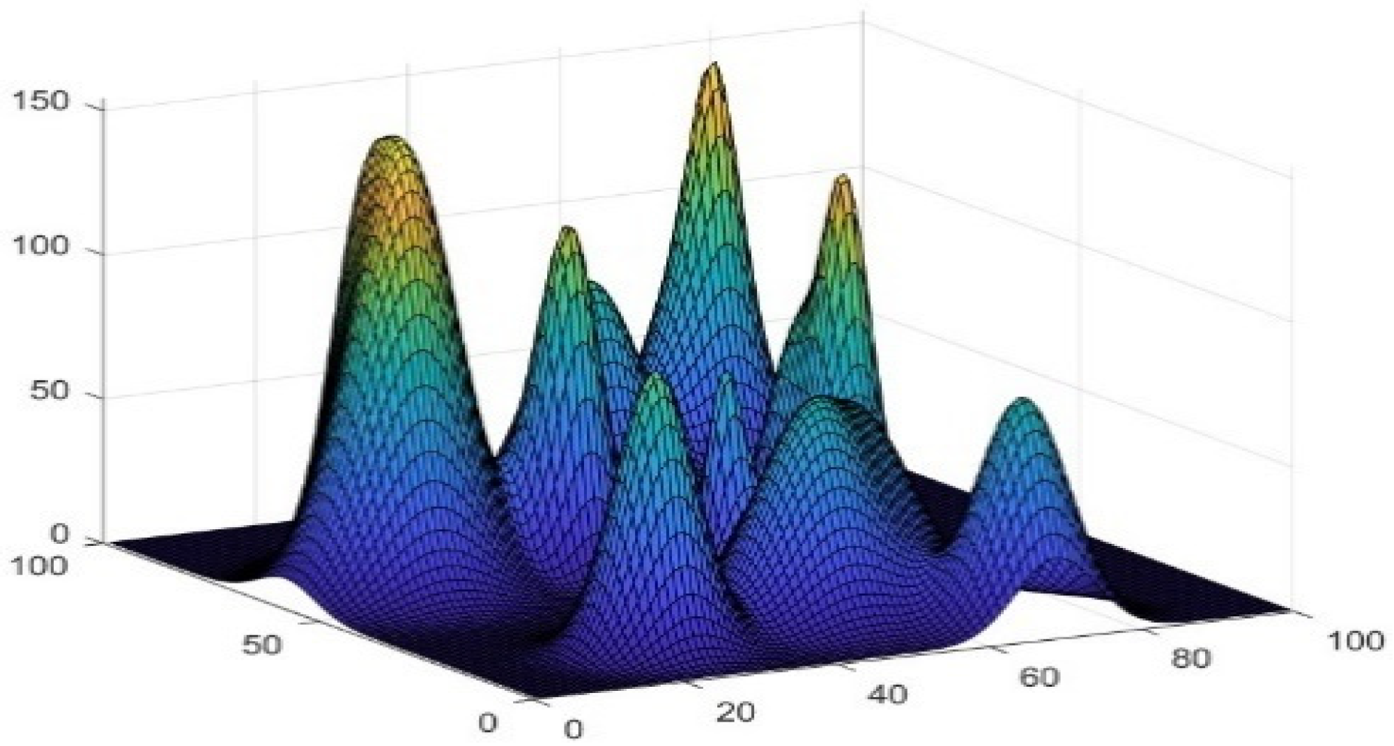
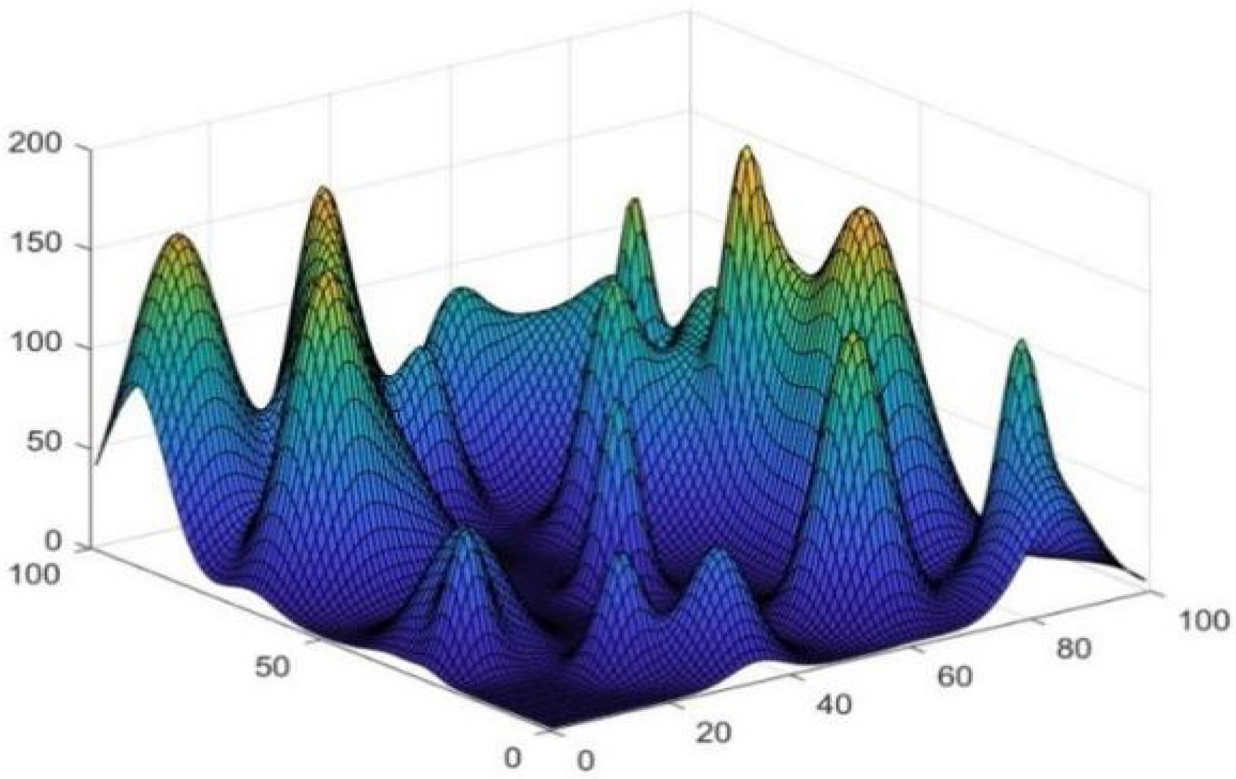
In order to visualise the results and the realism of the simulation environment, this paper selects the study to compare and verify the algorithm in a 3D environment. The 3D space is gridded and numerically coded to simulate the mountainous terrain environment, while the simulation object also includes the no-fly zone. In this paper, the 3D coordinates are planned as ** parts, and all the height information is represented by matrix H, with represents the coordinates of the three-dimensional height, in this study , then the simulated terrain map is shown below:
Figure 1.
The simulation generates mountainous terrain maps, and each simulation generates new maps to verify that the algorithm works for different environments.
Figure 1.
The simulation generates mountainous terrain maps, and each simulation generates new maps to verify that the algorithm works for different environments.
The specific expression for the matrix H is given below:
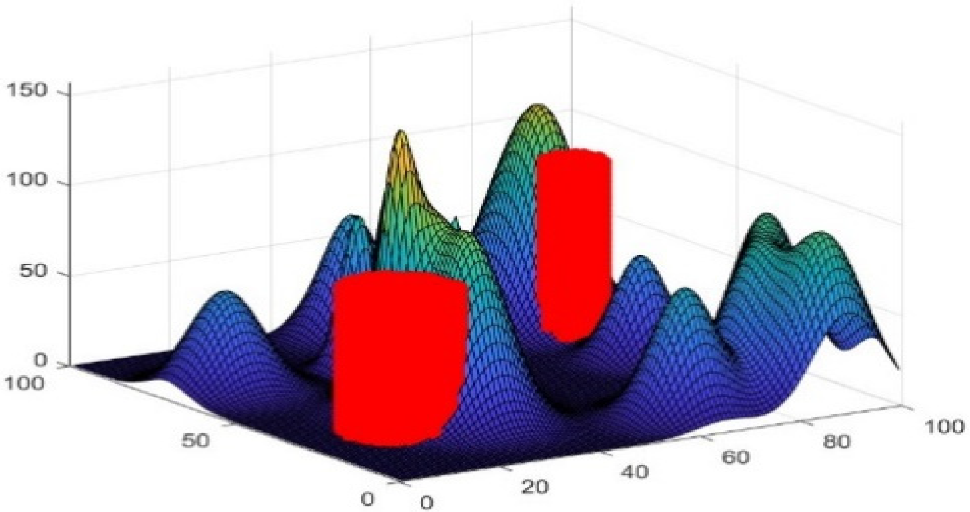
In the real environment, UAV flights are subject to many restrictions, such as crowded areas, military control areas and radar areas, etc. In this paper, these restricted areas are collectively called no-fly zones. In this paper, these restricted areas are collectively referred to as no-fly zones, which need to be avoided during UAV trajectory planning, and are set as cylindrical models in contact with the terrain surface model, and the simulation of no-fly zones is shown below.
Figure 2.
Add a simulated no-fly zone for cylinders to the simulated terrain map, where cylinders are not allowed to fly over at infinite heights.
Figure 2.
Add a simulated no-fly zone for cylinders to the simulated terrain map, where cylinders are not allowed to fly over at infinite heights.
Simulation of all cylinder model information is represented by a matrix as shown in Equation 2.
In the formula: , are the coordinates of the centre and radius of the and the radius of the centre of the threat zone, respectively. From the security point of view, the altitude of the threat zone is set to be infinite, i.e., no flight is allowed over the threat zone.
2.2. Consideration Functions
In order to find the optimal trajectory, it is also necessary to take into account the influence of different factors, and this paper uses a cost function to evaluate the influence of different elements.
In this paper, the total cost of the research design model is the sum of terrain constraint cost, boundary constraint cost, no-fly zone constraint cost, flight path cost, flight altitude cost, flight altitude change cost, and flight path smoothing cost. The objective is to minimize the cost of the solution
2.2.1. Terrain Constraints
In order to avoid collision with the terrain during UAV flight, the height of each point on each trajectory should be greater than the terrain height. In the experiment if it is lower than the terrain height, a positive value is generated indicating the degree of violation of the terrain constraint, otherwise it is 0.
where
represents the degree of violation of terrain constraints, H represents terrain altitude information, N represents trajectory altitude information, P represents a safety threshold to ensure that the altitude of the path point will not be lower than the altitude of the terrain, the actual value is adjusted according to the implementation of the task and the flight environment, usually set a few metres to several tens of metres, in this paper, the value of 1.
2.2.2. Boundary Constraints
In order to avoid the planned UAV trajectory from going beyond the flight region, the path algorithm is investigated with the requirement that each point on the trajectory does not exceed the bounds of the specified spatial coordinates. In the experiments if the boundaries are exceeded, a positive value is generated indicating the degree of violation of the boundary constraints, otherwise it is 0.
where
denotes the total extent to which the path point exceeds the left and lower boundaries of the map;
denotes the total extent to which the path points exceed the right and upper boundaries of the map;
denotes the matrix of the 3D coordinates of the total path points after interpolation;
denotes the total number of path points after interpolation;
Table S shows the first
path point, where
has two coordinate values of x and y; when
when
x coordinate value is taken, when
when
takes the y coordinate value;
Is a vector containing the extent of the map.
2.2.3. No-Fly Zone Constraint Costs
In order to avoid UAVs from colliding with buildings and staying away from restricted areas during flight, all no-fly zones are set as an infinite-height impenetrable cylinder model during the research process in this paper. The distance from each point on the trajectory to the centre of the no-fly zone circle is calculated and then this distance is subtracted from the radius. If this difference is less than zero, it is replaced by zero to ensure that there are no negative values.
where
denotes the degree to which the indicated path point has entered the no-fly zone, and
denotes the number of no-fly zones, and
denotes the track point, and
denotes the radius of the it no-fly zone, and
denotes the distance from the point on the track to the centre of the no-fly zone circle.
2.2.4. Cost of Flight Trajectory
In order to reduce the distance travelled, the shortest paths are sought during trajectory planning in order to save energy. This is done by calculating the square root of the sum of the squares of the differences in the coordinates of two neighboring trajectory points.
where
denotes the degree of flight distance, the
is the first
and
distance between the path points.
2.2.5. Cost of Flight Altitude Change
In order to ensure the safety, stability and energy efficiency of the UAV, the trajectory should be planned with as little altitude fluctuation as possible. This is achieved by calculating the variance of the altitude of the trajectory points during design.
where
denotes the degree of UAV altitude fluctuation.
2.2.6. Flight Altitude Cost
In order to maintain the advantages of UAVs flying at low altitude, such as good manoeuvrability, stealth, clarity of shots, low energy consumption, etc., the trajectory planning should try to ensure a low altitude, which is achieved by calculating the average value of the altitude of the trajectory points during the design.
where
denotes the degree of UAV flight altitude, and
is the number of path points.
2.2.7. Cost of Flight Path Smoothing
In order to ensure the safety of the UAV and its surroundings during flight, and the feasibility of the operation and its own structure, it is required that the path should be kept smooth during trajectory planning.
where
denotes the degree of angle of change in all directions, which is used to measure the smoothness of the path.
is the same as
represents the vector difference between two neighbouring points in the same direction as the UAV flight direction, and
represents the difference between
is the inverse cosine of the cosine of the angle between
the inverse cosine of the cosine of the angle.
3. Whale Optimization Algorithm
Whale Optimization Algorithm (WOA) is a meta-heuristic intelligent optimization algorithm based on the foraging behavior of whales, which was proposed by Seyedali Mirjalili and Andrew Lewis in 2016 [
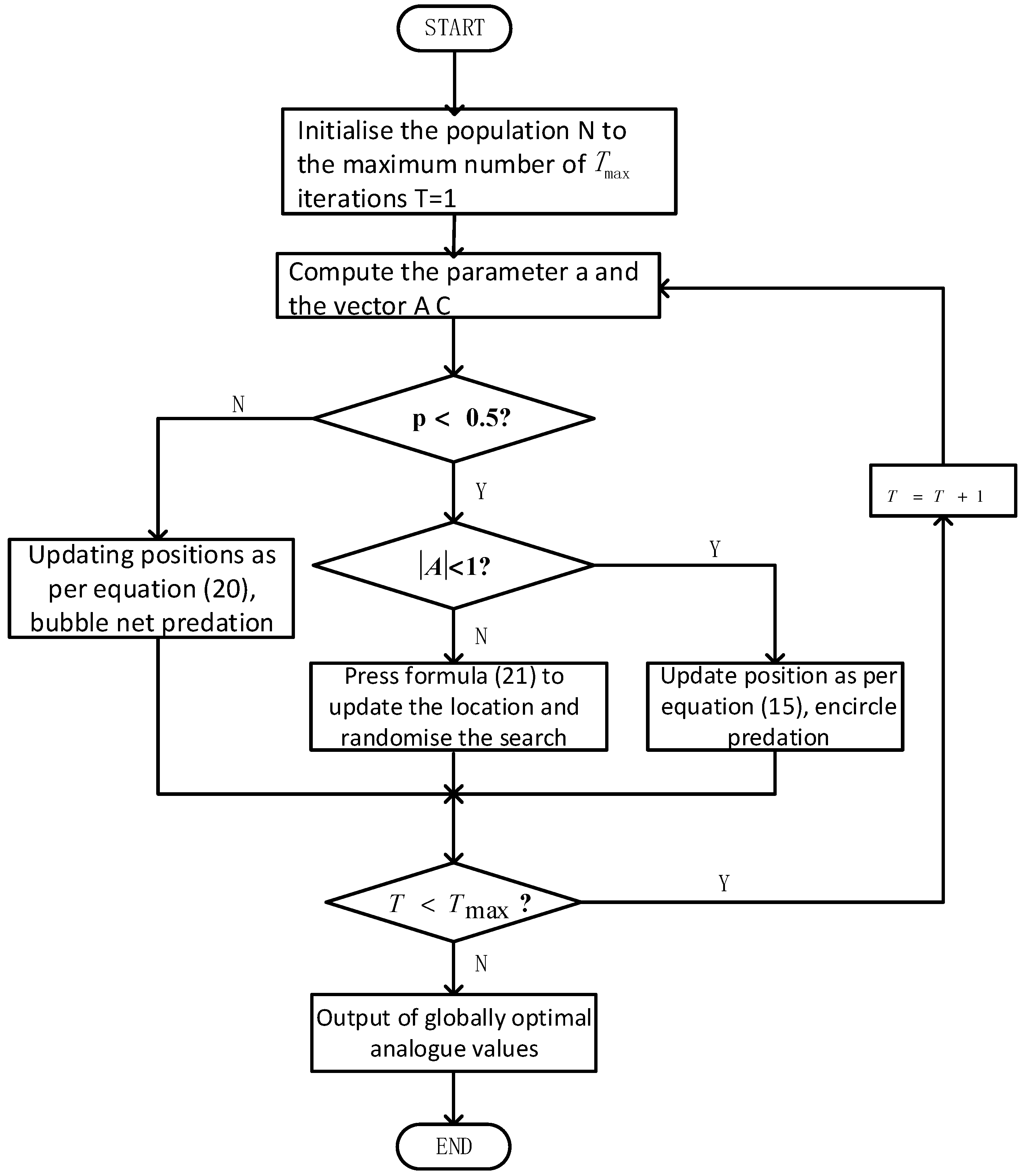
12]. The mathematical model is based on the three foraging behaviors of humpback whales: encircling predation, bubble attack and food seeking. The flow chart of the calculation is shown below:
Figure 3.
Whale optimization algorithm flowchart, the process reflects the stages of initialisation, encircling prey, bubble net predation method, searching for prey.
Figure 3.
Whale optimization algorithm flowchart, the process reflects the stages of initialisation, encircling prey, bubble net predation method, searching for prey.
3.1. Surrounding the Prey
The locally optimal solution for encircling the prey is the one closest to the food, and the other individuals gradually approach the locally optimal individual to encircle the food. The mathematical model for this stage is as follows:
Eq:
is the current optimal solution and
denotes the position of the ith whale in generation t. A and C are coefficient vectors with the expression:
where: r is a random number uniformly distributed on [0, 1] and
is the convergence factor, whose expression is:
where: t is the current number of iterations, and
is the maximum number of iterations.
3.2. Subsection Bubble Attacks
There are two attack mechanisms that occur during bubble net predation, the constrictive encirclement mechanism and the spiral updating position. The constriction-enclosure mechanism is encircling predation, which is achieved by lowering the value of the
value. Now assume that the probability of both is 0.5. The mathematical model for this stage is as follows:
Eq: is a random number on [0, 1] obeying a uniform distribution, and is a constant coefficient, and is a random number between [-1, 1].
3.3. Random Search
Referring to the whale at this point
has a value greater than 1 or less than -1, the search agent’s position in the exploration phase will be updated here based on the randomly selected search agent, not on the optimal search agent so far [
13].
where
denotes the coordinates of any whale.
4. Improving the Whale Optimization Algorithm
This section may be divided by subheadings. It should provide a concise and precise description of the experimental results, their interpretation, as well as the experimental conclusions that can be drawn.
The WOA algorithm has a simple structure with only a few parameters to be adjusted and is suitable for continuous and discrete optimization problems. However, on some complex high-dimensional problems, especially in solving spatially complex and multi-peaked problems, the convergence of WOA [
14] may be slower, and it still falls into the problem of locally optimal solutions even through a larger number of iterations. In this paper, an Improved Whale Optimization Algorithm (IWOA) is proposed. The IWOA algorithm uses reverse learning to increase the diversity of the initial population of the algorithm, and at the same time, the convergence factor is changed from linearly decreasing to nonlinearly decreasing, and a random number generation mechanism is integrated into the iterative process, which coordinates the global search capability and local development capability of the algorithm. The global search ability and local development ability of the algorithm are coordinated [
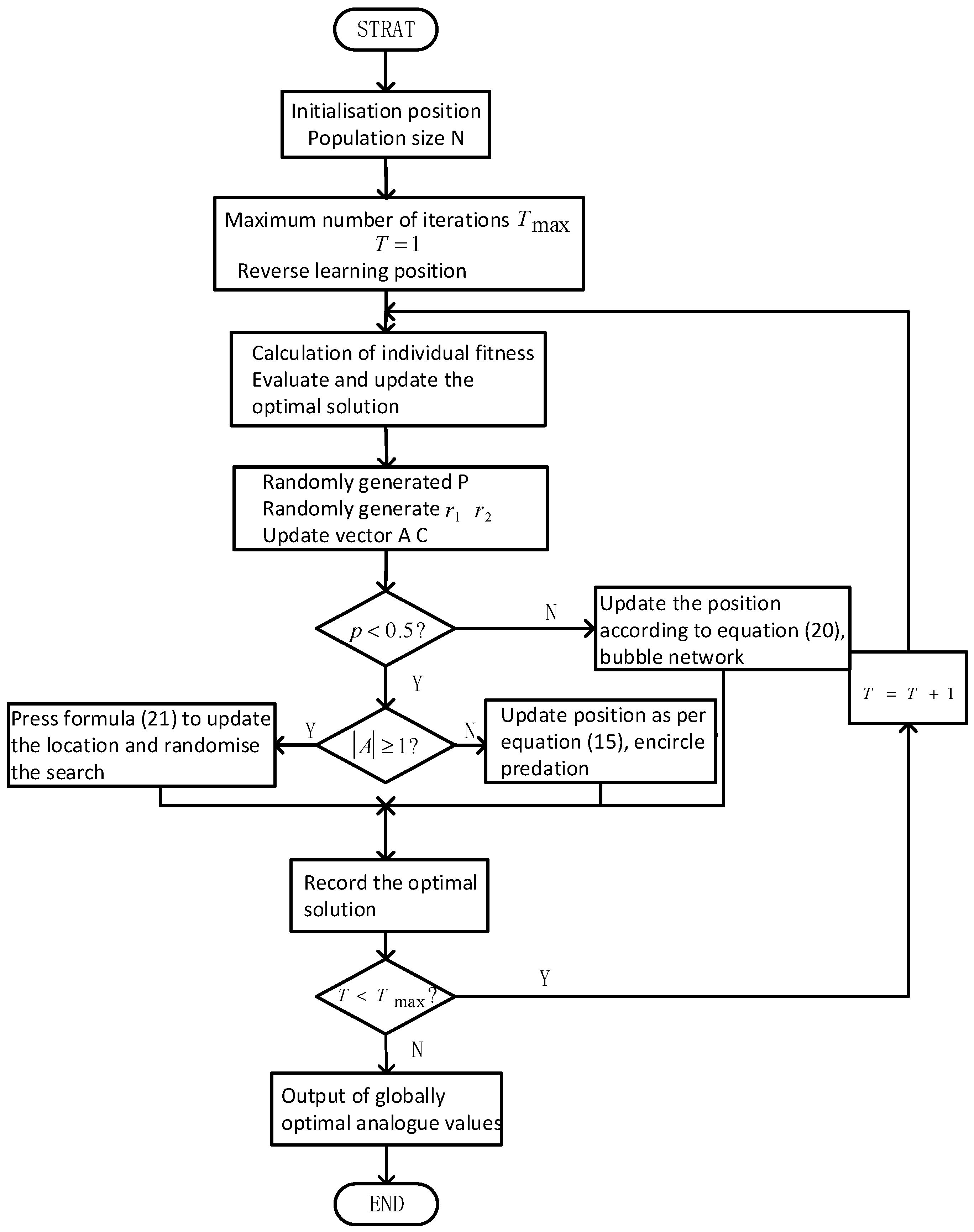
15]. The flowchart of the IWOA algorithm is shown below:
Figure 4.
Improved whale optimization algorithm flowchart, the process compared with the original algorithm in the initial stage with the reverse learning mechanism to expand the search range, the late addition of non-linear convergence factors to improve the ability to solve the local search.
Figure 4.
Improved whale optimization algorithm flowchart, the process compared with the original algorithm in the initial stage with the reverse learning mechanism to expand the search range, the late addition of non-linear convergence factors to improve the ability to solve the local search.
4.1. Reverse Learning Initialization
Inverse learning is a commonly used global optimization strategy that is currently proven and applied in many swarm intelligence algorithms [
16]. The idea of reverse learning is to use the current solution and its inverse solution to improve the search efficiency. In the study, it is assumed that the dimension of the search space is D, the population size is N, the upper and lower bounds of the search space are respectively
, the
, the initial population
of each individual is
and the inverse solution of the population
Each individual of the initial population is
and the formula is as follows:
where
is the backward learning factor, is
the random number on the.
At this point is the population after calculating the fitness update.
4.2. Nonlinear Convergence Factors
In WOA
is the convergence factor [
17], which decreases linearly from 2 to 0, as formulated in equation (19). At
approaching 2 due to the complexity of the space the step size of its searching agent decreases rapidly as a result, which makes the exploration range of the global searching phase shrink rapidly, resulting in missing some potential globally optimal regions. The convergence of the
the convergence of the algorithm from global search to local search can also be a premature shift from global search to local search resulting in local optimums. The algorithm converges to a local optimum at
approaching 0, the linearly decreasing convergence property slows down the change of its own value, which makes the step size of the local search not obvious enough, leading to the weakening of the ability to search in the vicinity of the local optimal solution. Aiming at the above problems this paper proposes a nonlinear convergence factor with the following specific formula:
In order to ensure that the time is close to 2, at time is close to 0, the design The .. The resulting smaller value of t in the early stages when the need to decline is slow, with little change in the numerator denominator, makes the less variation in the early stage and the global search capability is improved. In the middle stage the algorithm’s ability to balance between global and local search is improved because the convergence factor varies nonlinearly. In the late stage when fast descent is required, a larger value of t makes the rapid descent in the later stages and enhances the local exploitation capability.
4.3. Random Number Generation Mechanism
In population intelligence algorithms, it is common to generate random numbers to improve the algorithm’s global and local search capabilities [
18]. In this paper, the random number generation mechanism is used to optimize the algorithm in individual initialization, position update. During individual initialization, the random number
is used to determine the prey action to be selected when the individual is updated. For position update, the random numbers
is used to determine the predator action to be selected during the individual update,
parameter
,
are shown in Eqs. (17) and (18), and the index of the individual is selected by the random number. For the calculation of the nonlinear convergence factor, the random number
is guaranteed to
has randomness as shown in equation (24), so that it can produce different spiral trajectories and avoid the algorithm to fall into local optimum.
5. Simulation Verification and Result Analysis
In this study, the 3D space is planned as a 100*100*100 grid and 30 sittings of peaks are randomly generated as shown below:
No-fly zones are also planned in space, which are non-flyable cylinders with base coordinates and radii as shown in
Table 1:
5.1. Simulation Results
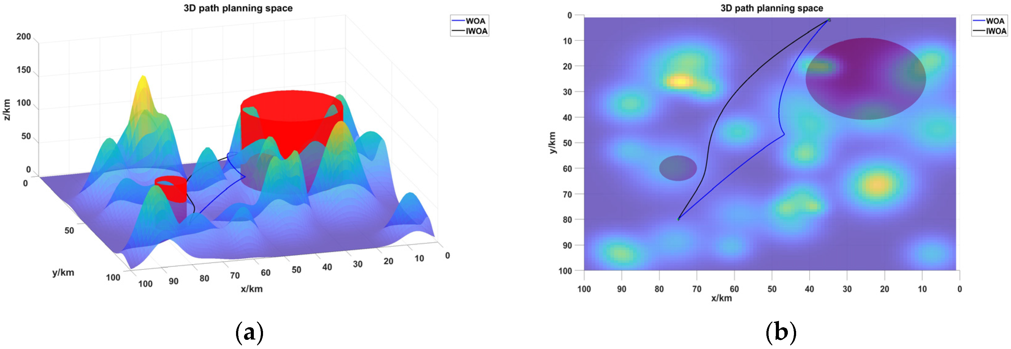
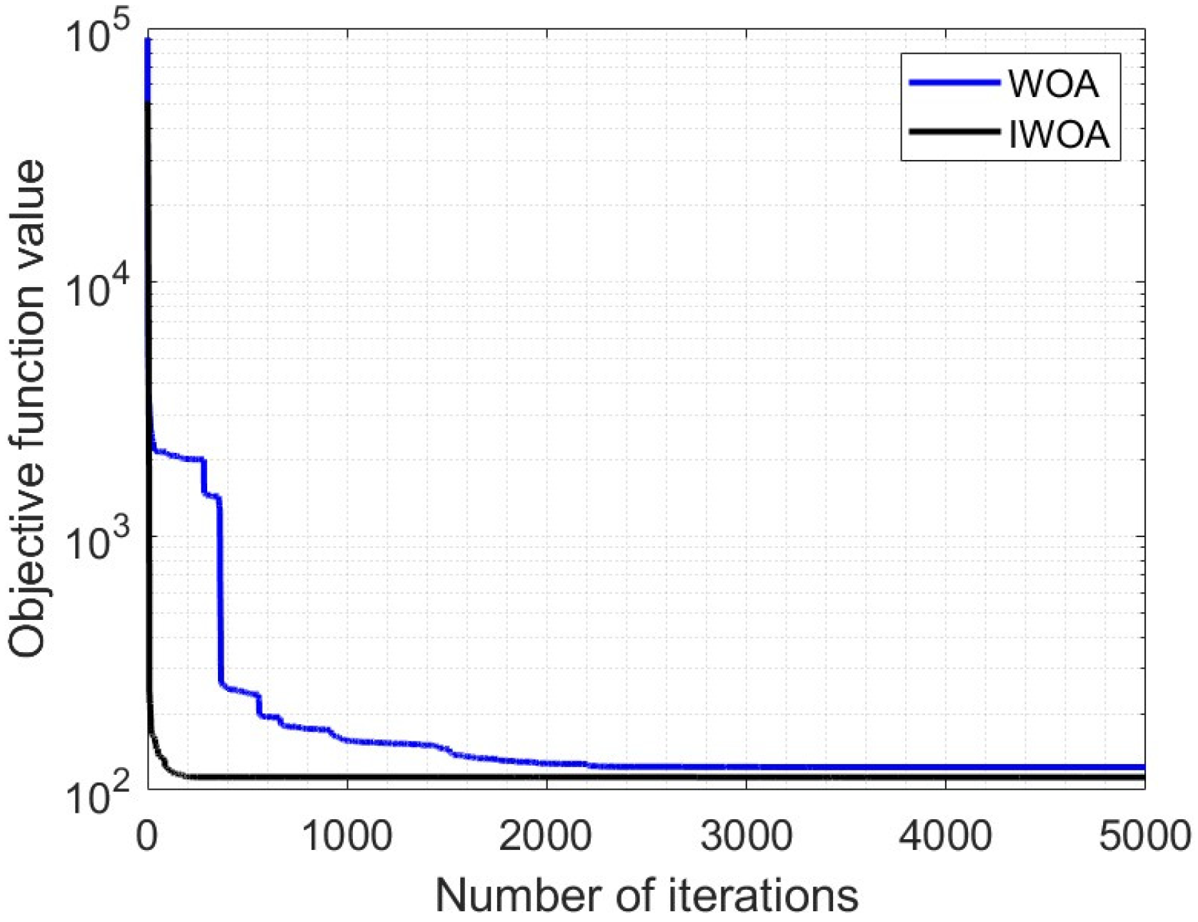
The whale optimization algorithm was modified as described above to study the UAV trajectory. Both algorithms assume a starting point at (35, 2) and an end point at (75, 80), with both heights varying according to randomly generated terrain. The calculation is set three times, the population size is set to 80, and each calculation undergoes 500 iterations. The performance information of the two algorithms is shown in
Table 2, the simulation results are shown in
Figure 6, and the convergence results are shown in
Figure 7.
5.2. Analysis of Results
Firstly, as shown in
Figure 4, the simulation results of the two algorithms in a unified environment, when solving the 3D trajectory planning problem, both algorithms are able to plan a smooth trajectory between the start and the end points and avoid collision with the mountain and the threatening area. Secondly, from
Figure 6(a), we can intuitively see that the IWOA algorithm chooses a shorter route to bypass the mountain and plan a shorter trajectory. And from Figur. 6(b), we can intuitively see that the IWOA algorithm plans a smoother trajectory when avoiding the mountain and the no-fly zone, which can effectively improve the safety of the UAV’s flight operations. This is due to the fact that the WOA algorithm enters the local search too early when solving the trajectory and falls into the local optimum. Finally,
Table 2 shows that the optimal value of the IWOA algorithm increases by about 0.882%, the worst value decreases by about 54.8%, the mean value decreases by about 22.1%, and the standard deviation decreases by about 74.1% compared with the WOA algorithm through five calculations.
Comprehensive analysis of the above shows that the algorithm can be effectively optimized by incorporating the improved methods of inverse learning, non-linear convergence factor, random number generation mechanism, which achieves the enhancement of global and local search capabilities IWOA algorithm can plan a smaller total cost, shorter total path and smoother trajectory compared to the WOA algorithm when solving such problems as three-dimensional trajectory planning.
Four common optimization algorithms were selected LO for Lemur optimization algorithm [
19] SWO is the spider wasp optimization algorithm COA is the coyote optimization algorithm [
20] KOA is the Keplerian Optimization Algorithm [
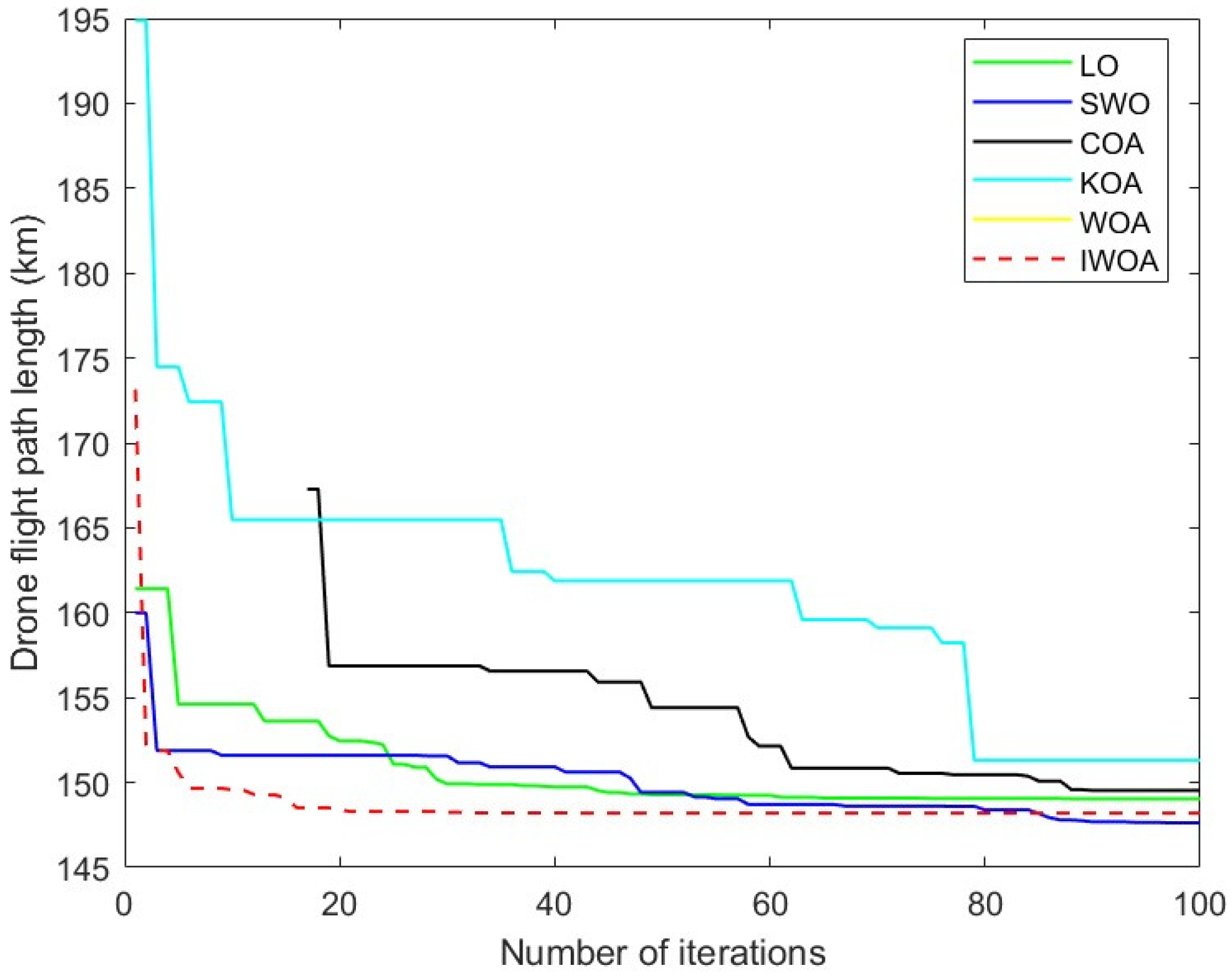
21] to verify the performance of IWOA algorithm. In the comparison test, the populations of the IWO algorithm and WOA algorithm proposed in this paper and the remaining six algorithms are set to 50, and the maximum number of iterations are set to 100, and the test results are shown in
Figure 8.
6. Results Conclusion
In this paper, based on the WOA algorithm, IWOA is proposed by incorporating inverse learning, adding nonlinear convergence factors, and random number generation mechanism. IWOA is able to plan UAV trajectories better than WOA in simulation experiments in compliance with the constraints, which indicates that the improved method solves the local optimum problem, improves the ability to deal with individual boundaries, and ensures the applicability of the algorithm on different problems. In future research, the introduction of more influencing factors to enrich the model will be considered on the one hand, and UAV trajectory planning in dynamic environment will also be considered on the other.
References
- Tao, Y. J.; Li, P. F. An Overview of UAS Development and Key Technologies. Aviation Manufacturing Technology 2014, 20, 34-39.
- Ma, Z.; Zhu, Q.; Zhang, J.; et al. Ant Colony Optimization Algorithm for UAV Indoor Trajectory Planning. J. Xi’an Univ. Sci. Technol. 2022, 42, 307-316.
- Deng, L.; Chen, H.; Zhang, X.; et al. Three-Dimensional Path Planning of UAV Based on Improved Particle Swarm Optimization. Mathematics 2023, 11 9-20. [CrossRef]
- Xu, L.; Zhao, W. UAV Trajectory Planning Based on a Novel Grey Wolf Optimization Algorithm. Electron. Meas. Technol. 2022, 45, 55-61.
- Fu, D.; Fan, P. Improvement of A* Algorithm for 3D UAV Path Planning. Intell. Compute. Appl. 2020, 10, 155-159.
- Funk, N.; Tarrio, J.; Papatheodorou, S.; Alcantarilla, P. F.; Leutenegger, S. Orientation-Aware Hierarchical, Adaptive-Resolution A* Algorithm for UAV Trajectory Planning. IEEE Robot. Autom. Lett. 2023, 8, 6723–6730. [CrossRef]
- Zhang, F.; Liu, Z.; Lin, D. Optimal Design and Implementation of UAV Trajectory Control Module. Compute. Technol. Autom. 2024, 43, 16-24.
- Yang, X.; Qu, D. A Trajectory Optimization Method Based on Genetic Simulated Annealing Algorithm. Sichuan J. Mil. Eng. 2013, 34, 66-70.
- Zhang, J.; An, Y.; Cao, J.; Ouyang, S.; Wang, L. UAV Trajectory Planning for Complex Open Storage Environments Based on an Improved RRT Algorithm. IEEE Access 2023, 11, 23189–23204. [CrossRef]
- Cherif, N.; Jaafar, W.; Yanikomeroglu, H.; Yongacoglu, A. RL-Based Cargo-UAV Trajectory Planning and Cell Association for Minimum Handoffs, Dysconnectivity, and Energy Consumption. IEEE Trans. Veh. Technol. 2024, 73, 7304–7309. [CrossRef]
- Yuan, J.; Liu, Z.; Xiong, X.; Ai, Y.; Chen, L.; Tian, B. UAV Path Planning With Terrain Constraints for Aerial Scanning. IEEE Trans. Intell. Veh. 2024, 9, 1189–1203. [CrossRef]
- Mirjalili, S.; Lewis, A. The Whale Optimization Algorithm. Adv. Eng. Softw. 2016, 95, 51-67. [CrossRef]
- Hua, W.; Huang, W.; Yu, F. Improved Model-Predictive-Flux-Control Strategy for Three-Phase Four-Switch Inverter-Fed Flux-Reversal Permanent Magnet Machine Drives. IET Electr. Power Appl. 2017, 11, 717-728. [CrossRef]
- Yu, J.; Gao, N.; Li, H. A Whale Algorithm Based on Nonlinear Convergence Factor and Local Perturbation. Compute. Eng. Des. 2019, 40, 2861-2866.
- Zhang, Q.; Long, W.; Li, Y.; et al. Wear Monitoring of Milling Cutter Based on Whale Algorithm Optimized LSSVM. J. Sichuan Univ. Nat. Sci. 2022, 59, 68-74.
- Wang, Y.; Huang, L.; Zhong, J.; Hu, G. LARO: Opposition-Based Learning Boosted Artificial Rabbits-Inspired Optimization Algorithm with Lévy Flight. Symmetry 2022, 14, 2282-2282. [CrossRef]
- Zhang, Y.; Du, S.; Zhang, Q. Improved Slime Mold Algorithm with Dynamic Quantum Rotation Gate and Opposition-Based Learning for Global Optimization and Engineering Design Problems. Algorithms 2022, 15 317-317. [CrossRef]
- Shuo, L. B.; Song, K. Z.; Wang, Y. F. FPGA Implementation and Research of Pseudo-Random Number Generator. J. Circuits Syst. 2003, 83, 121-124.
- Abasi, A. K.; Makhadmeh, S. N.; Al-Betar, M. A.; et al. Lemurs Optimizer: A New Metaheuristic Algorithm for Global Optimization. Appl. Sci. 2022, 12, 10057.-10057 . [CrossRef]
- Yang, Z.; Cheng, W. Optimization Method of Quadcopter UAV Formation Trajectory Based on Adaptive Coyote Algorithm. J. Changchun Norm. Univ. 2024, 43, 52-57.
- Hakmi, H. S.; Shaheen, M. A.; Alnami, H.; et al. Kepler Algorithm for Large-Scale Systems of Economic Dispatch with Heat Optimization. Biomimetics 2023, 8, 608-631. [CrossRef]
|
Disclaimer/Publisher’s Note: The statements, opinions and data contained in all publications are solely those of the individual author(s) and contributor(s) and not of MDPI and/or the editor(s). MDPI and/or the editor(s) disclaim responsibility for any injury to people or property resulting from any ideas, methods, instructions or products referred to in the content. |
© 2024 by the authors. Licensee MDPI, Basel, Switzerland. This article is an open access article distributed under the terms and conditions of the Creative Commons Attribution (CC BY) license (http://creativecommons.org/licenses/by/4.0/).
