1. Introduction
The ability to generate high-resolution volumetric images of material samples is of great importance for a wide range of research questions in the natural and material sciences. X-ray-based CT images of samples that are loaded and deformed during the measurement, i.e. where the measurement takes place in-situ, are of particular importance. This allows the observation of deformation processes and the progression of potential damage before the final failure of the sample. This enables the specific conclusions to be drawn about the material behaviour that would not be possible if the material sample were examined post-mortem. [
1,
2]
The aim of this work is to develop a laboratory CT system that fulfils the following requirements: The CT system should be capable of achieving a resolution of less than m and should be able to analyse samples of various materials, in particular those with low levels of absorption. Furthermore, the system should allow for the application of loads up to 5 kN in both tensile and compressive directions while the sample is being measured, and it should be possible to continuously record the applied force. These premises necessitate specific requirements for the equipment used and the mechanical design, which are discussed in the following.
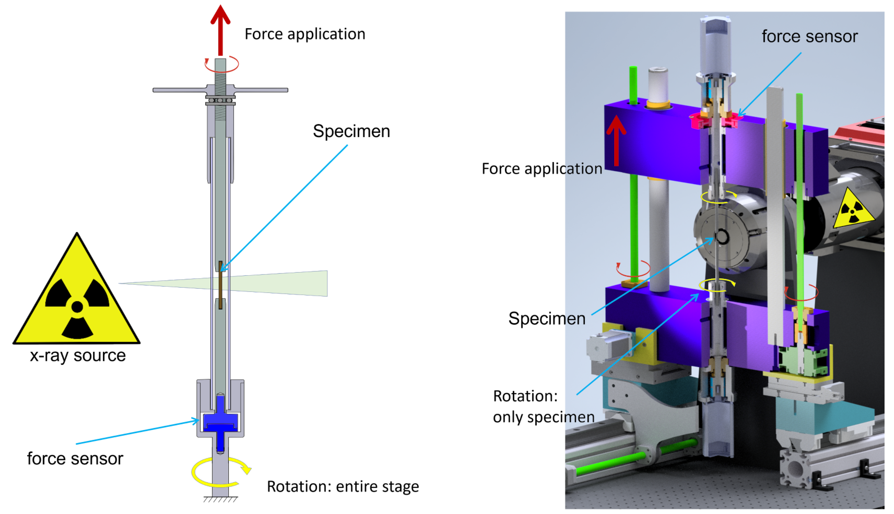
During CT measurement, the sample rotates around its own axis by up to 360°to generate X-ray images from different perspectives. For in-situ mechanical loading, i.e., when a force is applied to the sample along the axis of rotation, a structure must exist which channels the reaction force around the sample. This structure is referred to as the load frame. One is typically not interested in imaging the load frame, instead, only the sample should be visible in the X-Ray image. To achieve this, two different concepts can be employed:, which are briefly introduced in the following (see also
Figure 1).
Closed loading cage: A tube of a slightly absorbent material is placed around the sample. This tube redirects the reaction force of the applied force around the sample. As the tube remains permanently in the X-ray beam, it is important that its X-Ray absorption is low. It is also important that its optical properties are homogenoeous and invariant with respect to rotation, such that the absorption occurs evenly over the entire cross-sectional area of the X-ray beam and remains consistent for each projection. For each projection angle, the entire structure, comprising the sample, the tube, and the load application mechanism, is rotated.
With the closed cage, a force can be applied to a sample with a simple design. However, the additional absorption adversely affects the measurement result. This is a particular drawback for samples which are itself of low absorption and low-contrast. Additionally, since the tube has a certain diameter around the sample, the minimum distance between the X-Ray source and the sample is increased. This implies that the optical magnification in a cone beam X-Ray setup is reduced, compared to the situation without the tube.
Open loading frame: The tube carrying the reaction forces can be dispensed with by using a load frame outside the X-Ray field of view. To obtain artefact-free measurements, a full rotation of the sample around its axis of rotation is required for conventional reconstruction algorithms such as FDK. Consequently, the load frame must not enter the X-ray beam at any time, as stated in [
3]. The load frame does not rotate; only the sample in its fixture is rotated.
In an open load frame, the contrast range of the X-ray system can be fully utilised, as only the sample has an absorbing effect on the X-ray beam. If the load frame is dimensioned accordingly, the sample can be moved right up to the window of the X-ray source to achieve maximum geometric magnification. However, the mechanical complexity of the open frame setup is far more challenging than for the closed frame. As the closed frame simply only induces gravitational forces on the rotation stage only, very precise air bearings can be employed, yielding high stability of the optical axis. This is a prerequisite for successful reconstruction, as the reconstruction algorithms typically assume a stable system, with the only variation from image to image being an increment of the projection angle. For the open frame, in contrast, the axial load on the sample has to be transmitted through the bearings. For the here intended range of axial loads up to 5 kN, this implies that air bearing are too weak, and that instead, ball or roller bearings must be employed. As will be discussed further below, this is a challenging aspect for the targeted resolution below 1 m.
An important aspect of this work is that we deliberately focus on laboratory cone-beam CT. A number of CT results with resolutions of better than 1
exists in the literature, however, these are obtained in a parallel beam setup using synchrotron radiation [
4,
5,
6]. While the properties of this type of radiation provide a brilliant measurement result, the availability of synchrotron sources is limited. Conventional X-ray tubes with conically emitted radiation are comparatively cheap and available at many research institutes [
7]. The intention of this work is to demonstrate that sub-1
m resolution CT is possible for in-situ mechanical loading with cone-beam CT.
1.1. Existing Concepts for In-Situ ct
Setups for in-situ measurement of different material samples in laboratory CT are described by a number of authors employing a closed load cage. [
8] uses a simple load frame with a polycarbonate tube around the sample for the investigation of Al-Li-2090 samples. The tube has an outer diameter of 50.4 mm and a wall thickness of 2.8 mm, which leads to an attenuation of the X-ray beam by 35.6 % at the characteristic line of the silver target (Ag
= 22.5 keV). In the CT measurement, a voxel size of 6.5
could be achieved with this setup. Germaneau et al [
9] investigate the deformation of copper-doped polymer samples in CT and use a load frame with a PMMA tube in the X-ray neck to carry the load. The strongly absorbing copper particles with a diameter of about 150
m are visualised with a voxel size of 6
m.
The deformation of a vertebral cover plate due to the load caused by an implant was analysed by Hulme et al [
10] using micro CT. For this purpose, an in-situ loading device with a POM tube was used. The bone samples were equipped with several glass spheres with a diameter of 1 mm to set reference points for the deformation of the vertebral body. A voxel size of 82
m was achieved.
Lachambre et al [
11] used a loading device with a load-bearing aluminium shell for micro CT and subsequent full-field digital volume correlation (DVC) for analysis of the sample deformation. With an outer diameter of 16 mm, the sample axis could be moved correspondingly close to the X-ray source such that a voxel size of 3.5
m was achieved. The notched sample was made of spheroidal graphite cast iron. The contrast of the X-ray images was not sufficient to observe the progression of the crack, however, the residuals of the DVC algorithm were used for this purpose.
All of these in-situ experiments have in common is that a closed load cage was used. The effects of the polymer or aluminium tubes was ususally not quantified in terms of influence on the X-Ray image quality due to changes in absorption. However, it can be assumed that the tube contribution to the total absorption was negligible, as samples with relatively high absorption were imaged, which required the use of hard X-rays.
For in-situ measurement of samples made of weakly absorbing materials, such as polymers and other organic compounds, however, tubes made of similarly or even more strongly absorbing materials are, a priori, not suitable. Besides the already discussed restriction of a reduced geometrical magnification, closed frame loading cages do not appear suitable for high-resolution CT of samples with low X-Ray absorption.
We were not able to find reports in the peer-reviewed literature for open-frame loading devices. A commercially available 20 kN open-frame in-situ loading rig for CT imaging exists, [
12], which allows in-situ measurement under compression, tension and torsional loading. Due to the dimensions of the sample clamps, the minimum source-object distance is limited to around 45 mm. With additional efforts, the resolution could be increased to a voxel size of
in [
13]
In the following, the design and construction of a CT system is presented which overcomes the described limitations of increased absorption and reduced magnification.
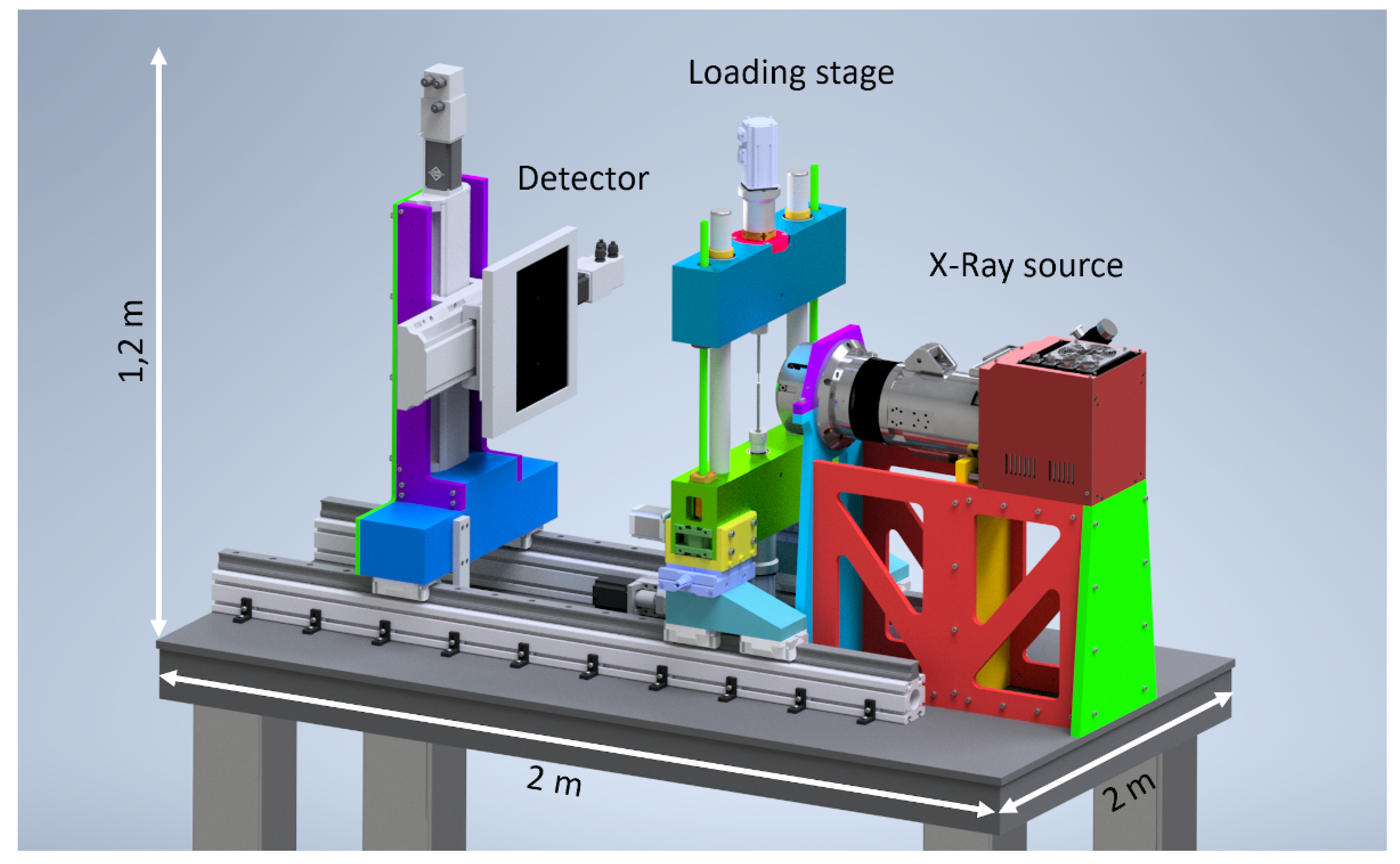
Figure 2.
The open design of the loading frame allows the sample to rotate freely and be moved directly to the X-ray source. Force is applied to the sample by moving the upper yoke of the loading frame. The loading frame and detector, as well as the force application, are realised by electromechanical components.
2. Materials and Methods
2.1. Requirements
2.1.1. X-Ray Setup
The microfocus X-ray tube L10711-03 from Hamamatsu Photonics, Japan, is employed as the X-ray source. The tube voltage can be varied in the range 20 keV to 160 keV. The tube is specified for a maximum resolution of 0.25
m using a beryllium target of 0.5 mm thickness and an opening angle of the emitted cone beam of 140°.
Figure 3.
The schematic structure of the load frame comprises an upper yoke that is guided with precision in a vertical direction via the preloaded ball cage when it is moved by the ball screw drive. The collet chuck, which holds the sample, is supported by high-precision bearings to ensure the axis of rotation when measuring under load. The load on the sample can be continuously analysed during an in-situ measurement via a force sensor that axially records the force on the collet, thereby providing a continuous measurement of the force exerted on the sample.
Two different detector systems are employed. We use a CMOS flat panel detector for large-format imaging and the majority of applications, while a photon-counting detector is optimal for specific energy-resolved measurements. The flat panel detector is a Rad-icon 2329 from Teledyne Technologies, USA, comprising a silicon scintillator. The detector has a resolution of 4608 x 5890 pixels with a pixel pitch of 49.5
m, a dynamic range of 3000:1 and a digitisation depth of 14 bits. For photon counting we employ a Timepix series direct measuring semiconductor detector. The Wide-Pix detector used consists of 15 Timepix sensor elements and delivers a resolution of 3975 x 265 pixels at 55
m pixel pitch. In TimePix detectors, incident X-ray photons can be evaluated for their energy or wavelength, which makes energy-resolved or spectral X-ray imaging possible [
14].
2.1.2. Load Frame Design
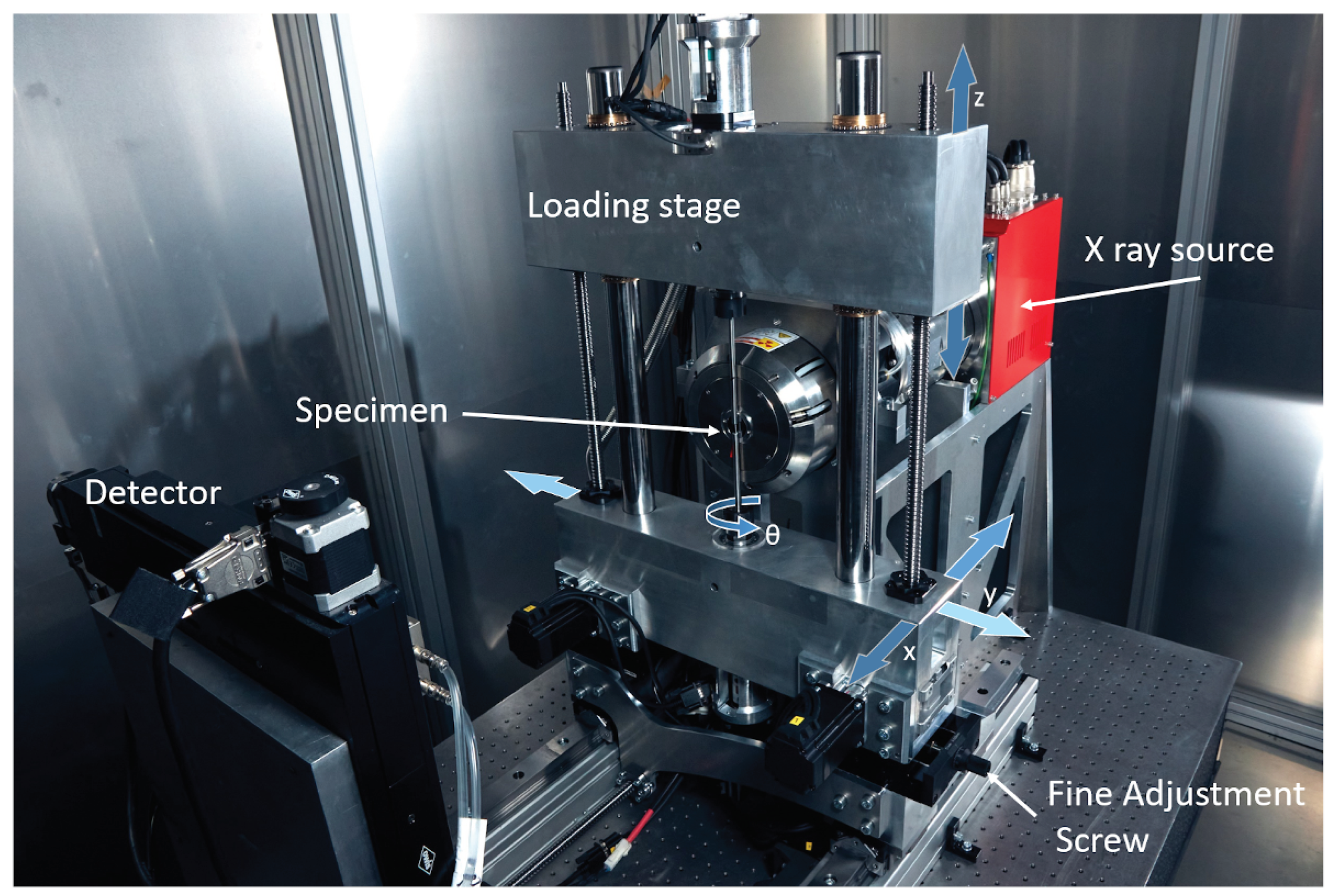
The load frame is a classic design, where a stationary base and a movable crosshead are joined by two vertical linear guides. The base and yoke are made from high-strength EN AW-7075 aluminium and house the drive components to effect vertical displacement and the rotary axis for CT measurement
Figure 4. The vertical displacement loads the testing sample and is realized using two symmetrically arranged ball screws (KGT-R-1605-RH-T5, Smalltec, Germany), driven by stepper motors (drive torque 2 Nm, Leadshine ES-M32320, China) with worm gear reduction (transmission ratio i=20, worm gears H/I Mädler, Germany). This allows to transfer a maximum force of 63 kN to the sample with a resolution of 0.83
m per step.
The vertical guides are two precision ground rods of 40 mm diameter on which the yoke slides using ball cage bearings (Fibro, Germany). The bearings are preloaded, to ensure zero radial play and (pairing classification and preload class 2) and thus only axial movement.
The rotary axis which provides different projection angles is realized using super precision roller bearings with a sliding inner ring and reduced internal clearance (NN3005C1NAP4, NTN, Japan). These bearings with tolerance class 4 according to ISO 429, constrain concentricity error, i.e., the radial run-out, of the inner ring relative to the outer ring to at most 3
m. The axial run-out is constrained using a standard fixed bearing block (FK15, THK, Japan) with a tandem arrangement of super precision axial bearings. This combination of roller bearings and fixed bearings was chosen to fulfil the axial and radial runout requirements laid out in Sec.
Section 2.1.
One FK15 bearing block is mounted to the load cell, which in turn is fixed to the base. The load cell is a ring-shaped force sensor with a nominal force of 5 kN (K3R, ME-Messsysteme, Germany). In this way, the axial load can be monitored while the axis is allowed to rotate. The second FK15 bearing block is mounted to the movable crosshead. Each of the FK15 bearing blocks accepts a rotary axis, which is a precision-ground rod with integrated collet holder (HFER25M-Z25-L1=150, Fahrion, Germany). Commercially available precision shafts with a diameter of between 3 mm and 12 mm are employed as specimen holders. The specimen is typically glued to these shafts using adhesives. The shafts are clamped inside the collet holders with precision collets.
We note that air bearings, which are otherwise considered the gold standard for a stable rotary axis in microtomography, were no option for us. Air bearings are not suitable for the high static axial loads required here.
The rotary axis is driven by two servomotors (EMJ-04AFD22 motor with PRONET-04AMG servo drive, Estun, China). Their 20-bit encoder delivers a theoretical angular step resolution of °, while the maximum achievable torque is 3.8 Nm. The servomotors share the same instruction signal line, ensuring synchronous operation to prevent the sample from twisting.
2.1.3. Mechanical Setup
Both the load frame and the detector are mounted on linear guides and can be moved along the optical axis using ball screws controlled by stepper motors. This allows to dial in different distances and thus different geometrical magnification factors.
Due to the high aspect ratio the Medipix detector – it is essentially a line detector –, rasterisation is necessary for two-dimensional images. For this reason, the detector is mounted to a motorized table, which allows the detector to be moved in the plane normal to the optical axis. The detector is connected to an adapter plate and can be easily interchanged with the flat panel detector. A reproducible connection is ensured by a positive locking mechanism of dowel pins.
2.1.4. Electromechanical Control
The entire control system is housed in a control box, with the stepper drives and servo drives connected to corresponding 24 V or 48 V power supply units. All mechanical degrees of freedom are controlled by using the Grbl motion controller [
15], which accepts G-code instructions over a serial interface. A custom computer program written in Python facilitates the positioning tasks of detector and load frame before the measurement, as well as the movement of the rotary axis to achieve different CT projection angles. This computer program also controls image acquisition with the detector, starting exposure sequences and reading ouzt the detector to hard disk.
2.2. Cooling System
A necessary requirement for successful reconstruction of projections to topographies is that both rotary and optical axes remain stable during the acquisition time, which can be on the order of several hours. It is therefore mandatory that heat generated by its electrical componets is removed from the system to avoid thermal expansion and the associated changes in geometry. At the same time, the temperature within the x-ray tube must be kept constant to achieve a constant photon flux, which is neccessary for constant exposure statistics of the specimen. While the latter requirement is neccessary for CT at all scale, the former becomes critical for CT at the sub-m scale, because dimensionals error due to thermal expansion are measured relative to a very small length scale. This has made it neccessary for us to build a custom cooling system which is detailed in the following, starting with a numerical analysis of the thermo-mechanical behaviour.
2.2.1. Structural Effects Due to Thermal Expansion
The X-ray tube, detector and load frame are components consisting of multiple materials with different thermal expansion coefficients. We require a prediction of how these components move relative to each other. This prediction is necessary to infer maximum allowable temperature differences between the components, to limit geometry changes due to thermal expansion.
To this end, a thermal simulation was performed using FEM. This was possible, because all parts of the system are modelled within the CAD software Autodesk Inventor, which contains the FEM solver Nastran. For this analysis, it was assumed that the optical table remains at a constant temperature, and the CT-system mounted to it is subjected to a temperature change.
We have found that the dominant source of geometrical errors is due thermal stresses arising from the aluminium structures mounted directly to the table: the table is constructed from a stiffened steel honeycomb sandwich structure comprising six millimetre-thick top layers and a core height of 200 millimetres. An 80 millimetre-wide aluminium profile is mounted on the table, with brackets at 100 millimetre intervals used to anchor it. The linear rails are fixed to the aluminium block. An increase in temperature would results in the aluminium profile expanding, which causes the table top to bend and thus tilt the X-ray beam. The second-most dominant error term is the movement of the sample relative to the x-ray source, which results in changes of the magnification.
Using the FEM model, we for the maximum permissible temperature change according to the following constraints: (i) The optical axis must not move more than one pixel within the detector plane, i.e., 10 m. (ii) The source-to-object distance must change less than 1 m. The simulations predicts that, if the temperature of the structure increases by 2°K during the measurement period, bending of the structure at a source-detector distance mm and source-object distance of mm would result in a vertical shift of the optical axis on the detector of 8.9 m. This temperature change also causes a horizontal expansion of SDD and SOD by m and m, which leads to a change in the magnification ratio.
The geometric magnification m results from
and thus by changing one of these variables to
and
which shows the dominant quadratic sensitivity of SOD. The magnification changes
, and
, lead to a total magnification difference of
. The projected change in position P of a point at a distance of
mm from the centre on the object side is therefore given by
which may be considered insignificant compared to the pixel pitch of the detector, 50
m
2.2.2. Thermal Management of the X-ray Tube
As X-ray sources convert less than 1% cent of the supplied energy into X-rays, a considerable amount of heat must be dissipated to the outside of the measuring chamber in order to ensure a stable photon flow [
16]. A constant temperature of the X-ray anode is relevant for longer measurements, as the emitted photon current changes with a change in its temperature and also favours a migration of the focal spot [
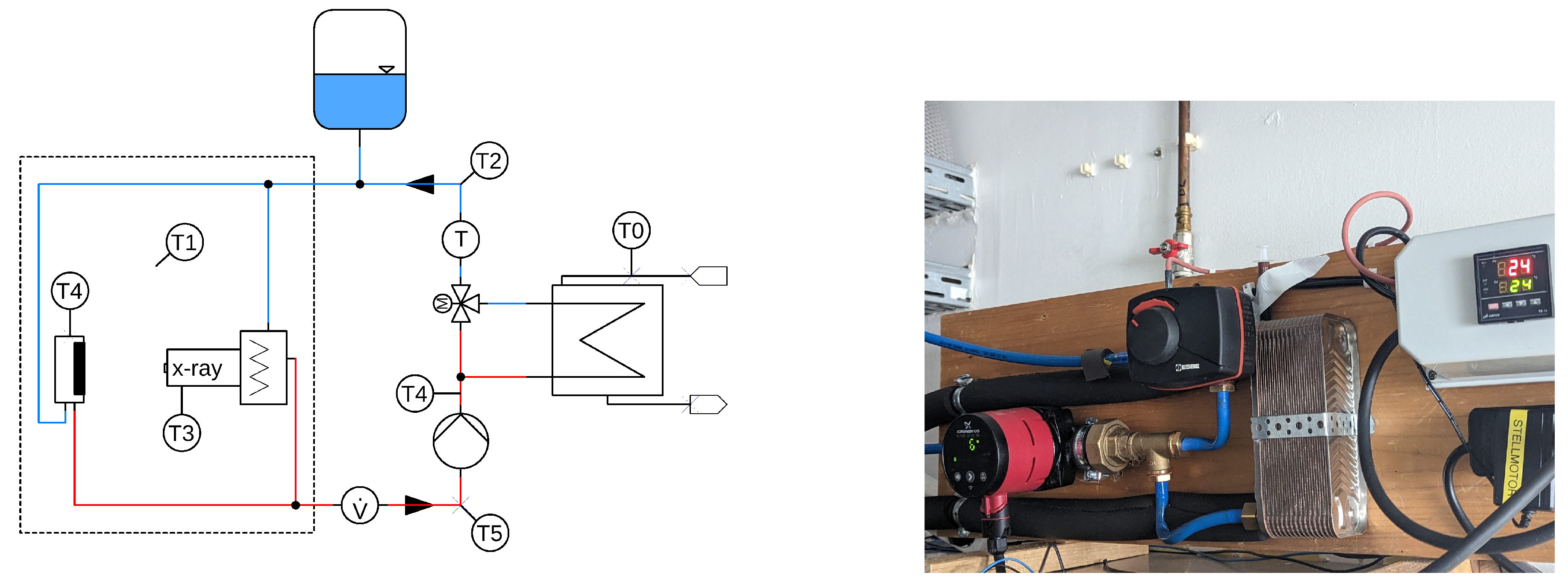
17]. A water cooling system was installed for this purpose, which is shown schematically in
Figure 5. Driven by a circulation pump, the coolant flows through the X-ray tube (and if a detector with cooling connections is used, also through that) and out of the measuring chamber. The flow is then split and part of it passes through a plate heat exchanger (30 plates, max. 66 kW, Wiltec, Germany), which is connected to an external recirculating coolant flow of the laboratory (
). Constant temperature of the coolant is realised by a PID controller and a 3-way mixer, which regulates the mixing ratio of both flows. To avoid condensation inside the X-ray tube and the measuring chamber, the coolant temperature should be within the ambient temperature range. We use (
) as the target temperature. At a volume flow of (
), the setup reliably regulates a temperature jump in the single-digit range to the target temperature within 3 seconds. However, with the smooth heat input from the X-ray tube and the detector, no temperature jumps are to be expected. The tube emits a relatively constant 50 W of heat.
2.2.3. Thermal Stability
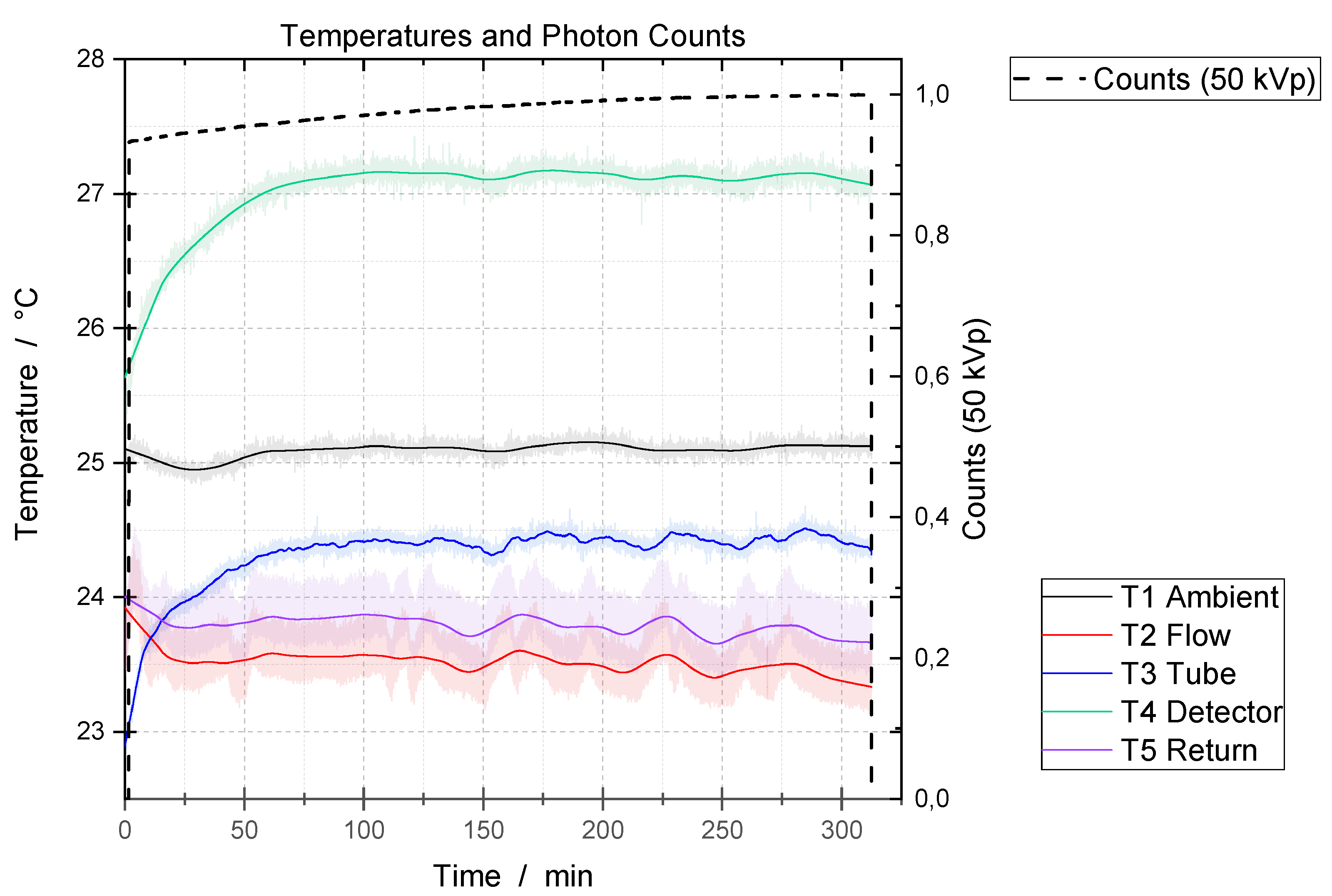
Initial investigations with an uncontrolled cooling circuit and a closed measuring chamber without heat extraction have shown that the measuring environment heats up to an unacceptably high level during longer measuring campaigns. At temperature increases of over a measurement period of 8 h, a significant drop in the photon current was also observed.
In contrast, with active cooling, the temperature and photon counts are stable with respect to time, once a period of equilibration has passed, see
Figure 6. This data is from a recording of 6 hours length. Sensors were attached at the locations T0 – T4, c.f.
Figure 5), in the measuring chamber. At the beginning of measurement, the X-ray tube is at room temperature. The tube is switched on (tube voltage 50 kVp, tube current 140 uA, anode current 10 mA) and starts to warm up. Over the first 100 minutes, a sharp rise in the temperatures of the X-ray tube and detector can be observed. After this equilibration period, all temperatures remain within approximately
. In particular, the tube temperature remains stable within
.
In addition to the temperatures,
Figure 6 shows the photon flux intensity as a function of time. From 100 minutes onwards, the flux is stable with a slight increase of less than 3% over 4 hours. It should be noted that the stability of the photon flux also depends on other factors.
The present cooling concept is thus sufficiently functional for long measurement campaigns with the CT system. The temperatures are constant with fluctuations within the limits shown, which means that no significant measurement inaccuracy or artefacts due to thermal expansion of the structure are to be expected, as outlined in Sec.
Section 2.2.1. The photon flux is also sufficiently constant for long CT measurements, see [
18] for an analysis of the stability requirements.
2.3. Concentricity and Stability of the Rotation Axis
To determine the runout, a 6 mm test pin of tolerance class 0 according to DIN 2269 (roundness: 0.5
m) is inserted into the upper and lower sample holders,, i.e., the collet chucks. Both the concentricity tolerance and the axial run-out are determined in several rotations at a distance of around 10 mm from the collet using a mechanical test indicator (MarTest 800 SGE, Germany, 1
m scale division). The data in
Table 1 shows the runout to be ≤ 3
m.
For an independent measurement, the rotation axis is quantified from image projections using an analytical approach. A high-precision steel sphere with a dimensional and shape tolerance of 0.08 m (diameter 0.8 mm, tolerance class G3) is mounted rotationally eccentric on a sample holder. Projections at 360 discrete angular positions within one full rotation turn are collected with the X-ray system. The trajectory of the sphere’s projections from the sphere’s centres of gravity results in an ellipse whose minor axis becomes larger the further away it is from the X-ray source-detector optical axis. By analysing the trajectories at different vertical distances of the steel sphere, the tilting of the system around the optical axis can be precisely determined. The distances of the optical system, source-detector distance and source-object distance are determined and calibrated by measuring points at different distances and by utilising the sphere diameter.
2.4. Positioning Repeatability of SOD and SDD
The positioning accuracy and, in particular, the repeatability of the SOD and SDD positions were determined using a mechanical feeler lever measuring device, with a result of less than 10 m. It should be noted that due to the backlash of the ball screws, accurate positioning is only guaranteed if the approach is always from the same direction. Automatic backlash correction is implemented in our control software environment by ensuring that the last section of a positioning move always occurs along the same direction.
2.5. Accuracy of Force Measurement
To validate that the force measured by the load frame’s force sensor corresponds to the force applied to the specimen, an axial force sensor was clamped between the collets. This sensor had previously been calibrated in a universal testing machine of the 0.5 accuracy class. Five series of measurements were carried out with different load speeds and cycles up to 1200 N in tension and compression. The force acting on the sample differed from the reference by less than . This difference can be explained by the bearing design: The roller bearings fixing the radial position of the rotation axis permit axial movement, but they require a few turns of rotation to completely eliminate friction. This is the case during a CT measurement, but not during the static situation considered here.
2.6. 2D Resolution of the System
The combination of the fine focus tube and the detector allows for a theoretical limiting resolution of 0.25 m (focal spot size in high resolution mode). During a CT measurement, the sample is rotated around its axis in the sample holder, and a safety distance from the X-ray window must be maintained to protect the sensitive beryllium target from damage in the event of sample rupture. Therefore, a minimum distance of SOD = 3 mm is considered to be a practical minimum. A sample cross-section of 2 mm allows for the realistic theoretical spatial resolution of 0.4 m to be achieved (geometric data: detector width 5890 px, SDD = 437 mm).
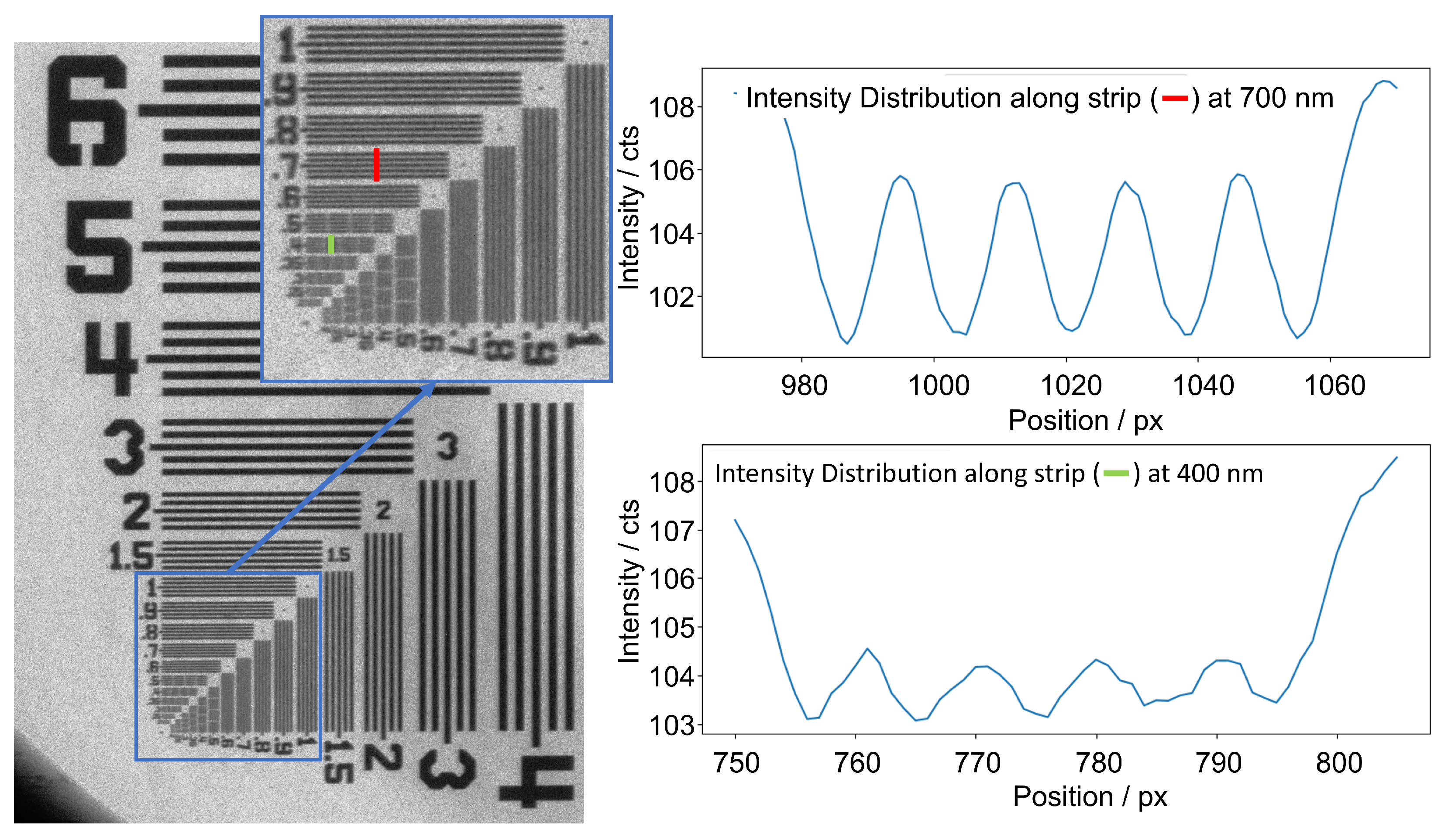
To prove the actual ability of the system to achieve a sub-micrometer spatial resolution, a 2D test target (XRN-SCT-0054, XRnanotech, Villigen, Switzerland) was imaged, which contains line pair pattern with distances between 0.4
m and 50
m. In
Figure 7, the intensity distribution along the vertical red line is plotted across the 0.7
m lines. For this purpose, 10 pixels were averaged in the direction of the stripes. It can be shown that the 5 line pairs of the 0.7
m structure can be clearly distinguished from the background noise. As a benchmark, the 5 minima of the 400 nm line group can still be significantly differentiated in this setting (green line). The following measurement parameters were used: X-ray voltage 80 kV, X-ray current 148
A, 120 measurements averaged at an integration time of 500 ms, SDD 840 mm, SOD 4 mm. A sub-
m spatial resolution can therefore already be realised in the 2D image [
19].
3. Results and Discussion
Validation of the setup was carried out with a basalt fibre-reinforced plastic that had already been characterised and measured in other systems [
20]. It is a quasiisotropic multilayer composite consists of the 8 layers
, with the outer two 0°layers running parallel to the load direction and the inner two layers orthogonal to it. The sample with a cross-sectional area of 1.6 mm x 2 mm was glued into precision shafts with a diameter of 6 mm and clamped in the sample holder of the load frame. The CT settings and parameters used here are listed in
Table 2. The geometric magnification leads to a geometrically native resolution of 0.7
m, which corresponds to the realistically attainable resolution of the system as shown
Section 2.6. The first measurement was carried out in a load-free state. Subsequently, tensile loads of different magnitude were applied and CT imaging was performed at each loading stage. The reconstruction of the image data was carried out using an OSEM-type iterative algorithm from a commercial reconstruction toolbox [
21].
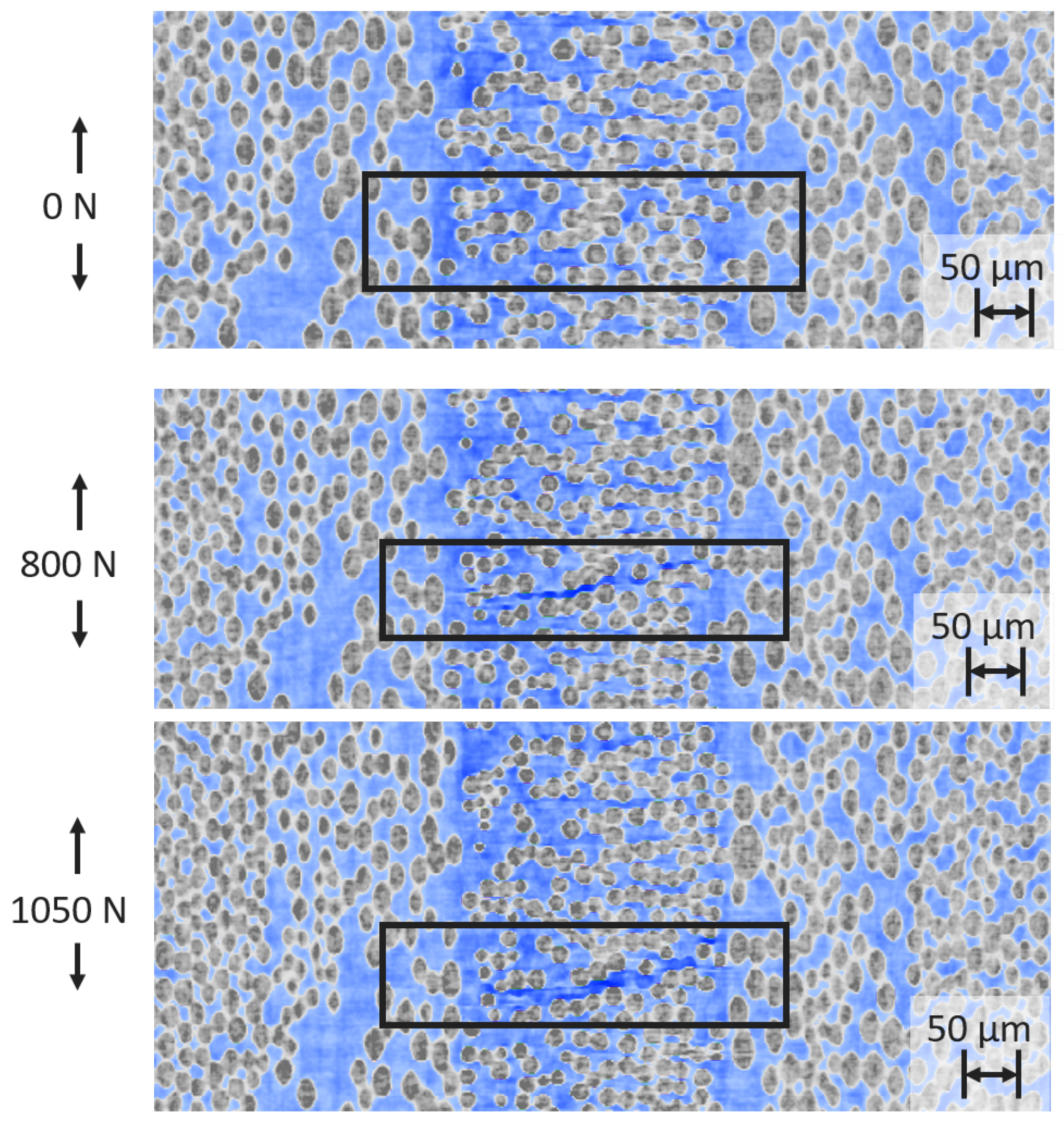
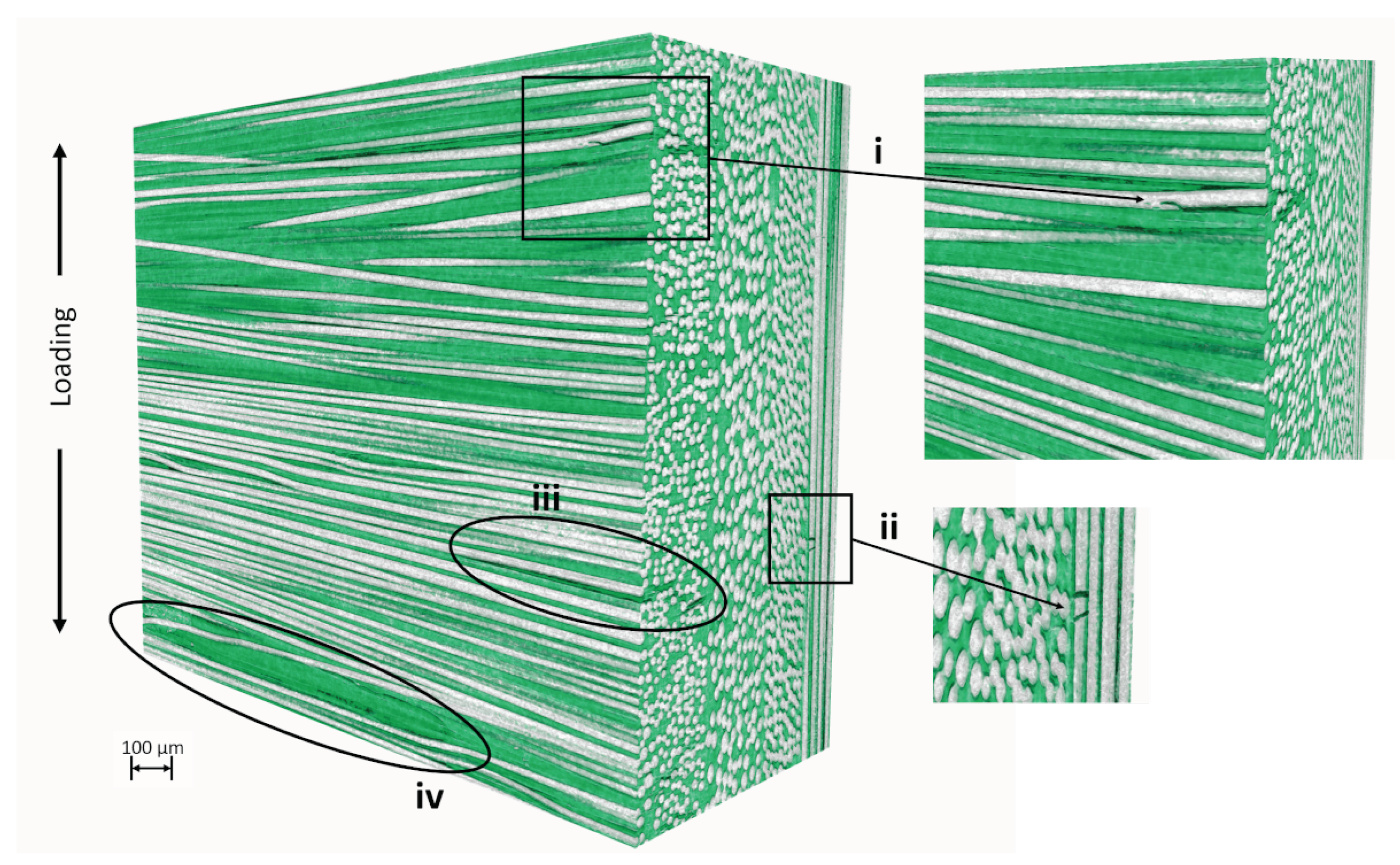
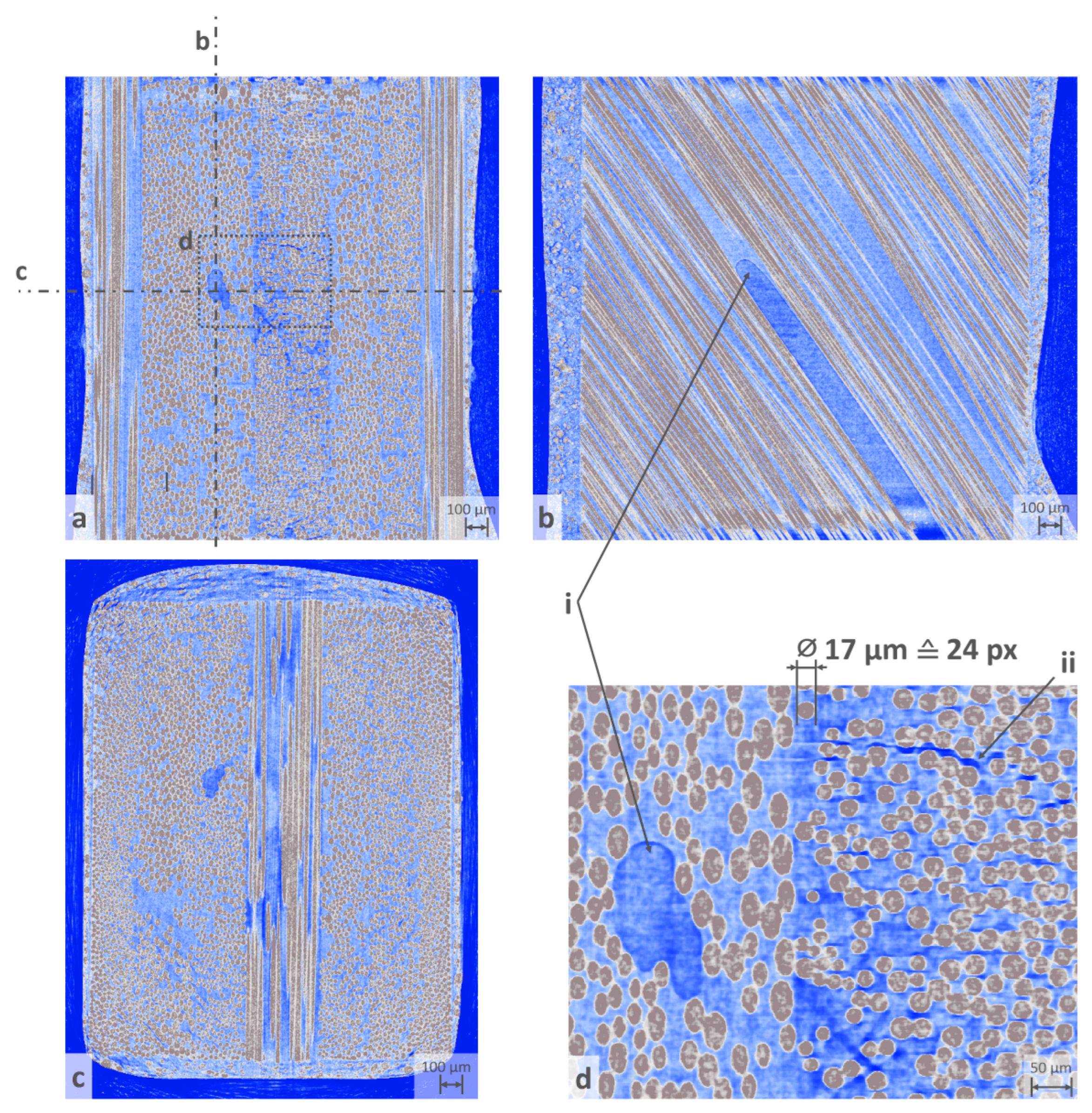
Figure 8 shows 3 sectional images of the reconstructed volume. The highly absorbing fibres can be clearly and continuously displayed free of imaging defects and artefacts. Artefacts in the volume such as ring artefacts are hardly noticeable. Beam hardening effects due to the heterogeneity in the absorption of the materials can be surmised in the corners of the top view. The weakly absorbing epoxy matrix is also resolved with sufficient contrast. It is remarkable that even defects such as air pockets (detail i) and damage to the laminate due to the increasing load can be inferred from the image (inter-fibre break or microcrack, detail ii). The interfibre fracture occurs as the load on the sample increases, as can be seen in
Figure 10.
The intensity distribution along a line through the reconstructed volume, shown in
Figure 9, provides information about the resolution of the system under these test conditions. This so-called edge spread function edge function shows the jumps from weak absorption (matrix) to maximum absorption (fibre). Over an average distance of
px, the contrast increase is
intensity values. Given the pixel-to-length ratio of 0.7
m, this implies that individual features smaller than 2
m can be recognized in the image, underlining the capability of the setup to achieve good quality imaging for difficult materials such as fibre-reinforced polymers.
Figure 9.
The left image shows a line (red, "c") along which the image intensity is sampled. The corresponding intensity profile is shown on the right. The intensity profile starts around zero, corresponding to the absorption of air around the sample. The absorption then switches rapidly between fibre material (image value around 5000) and expoxy matrix/air pockets (image value around 800).
Figure 10.
A basalt fibre epoxy laminate with a quasiisotropic layer structure is loaded vertically and three load states are shown. While the edge layers running parallel to the tensile direction bear the main load (not shown in the picture), intermediate fibre breaks occur in the middle 90°layer.
Figure 10.
A basalt fibre epoxy laminate with a quasiisotropic layer structure is loaded vertically and three load states are shown. While the edge layers running parallel to the tensile direction bear the main load (not shown in the picture), intermediate fibre breaks occur in the middle 90°layer.
Figure 11.
The volumetric rendering shows details such as fibre fractures (i, ii), inter-fibre fractures (iii) and air inclusions in the matrix (iv). Damage i-ii only occurs from a considerable load condition above 75% of the expected universal tensile strength.
Figure 11.
The volumetric rendering shows details such as fibre fractures (i, ii), inter-fibre fractures (iii) and air inclusions in the matrix (iv). Damage i-ii only occurs from a considerable load condition above 75% of the expected universal tensile strength.
4. Conclusion
This work demonstrates the suitability of the open-frame loading frame type for high-resolution in-situ Microtomography. The implementation presented here achieves a native spatial resolution of 0.7 m in projection images. Sample CT data for a fibre-reinforced material shows that the device is capable of identifying minute damage and fracture details at a scale well below a single fibre diameter, i.e., individual features with a size of m can be recognized.
The open-frame construction allows for maximum geometrical magnification, as the X-ray source can be placed directly in front of the object. This is in contrast to the integrated type of in-situ loading devices, which is placed on the rotation stage of an existing CT setup, such as the well-known stages from the manufacturer Deben, UK. However, the open-frame design comes at a price: As the rotation axis also has to transmit axial forces, the use of high precision air or magnetic bearings is prohibitive, as these cannot carry the high axial loads 10 kN required in our case. Instead, roller bearings have to be employed. Our design uses a bearing arrangement similar to high-precision machining spindles, with dedicated axial and radial constraints of the degrees of freedom. We show that this design works satisfactorily for the intended use of in-situ computer tomography of heterogeneous materials, such as the here presented results for a fibre-reinforced composite. A second advantage which comes with the open-frame design is that the X-ray spectrum only need to pass through the object, but not through an additional as in the case for integrated loading stages. This means that materials with very low absorption characteristics can be investigated with the open-frame design, as the X-ray spectrum not filtered.
Author Contributions
Conceptualization, validation, investigation and funding acquisition, D.P., G.G., M.S. and F.F.; methodology, G.G. and D.P.; software, M.C.; resources, G.G. and M.F.; data curation, D.P., M.S., F.F. and M.C.; writing—original draft preparation, D.P.; writing—review and editing, D.P. and G.G.; visualization, D.P. and F.F.; supervision, S.H. and G.G.; project administration, G.G. All authors have read and agreed to the published version of the manuscript.
Funding
The authors thankfully acknowledge funding of this work by the Gips-Schüle Stiftung, Stuttgart, Germany. G. G. gratefully acknowledges funding from Carl-Zeiss Foundation, Germany, Grant Title Skalenübergreifende Charakterisierung robuster funktionaler Materialsysteme. D.P. gartefully acknowledges funding from DFG, grant title "Vollspektroskopisches Timepix3 CT-System für Untersuchungen von Materialien auf mesoskopischer Skala", grant No. 414141599,
Acknowledgments
We extend our sincere gratitude to the late Helmut Zettl at Fraunhofer Ernst-Mach-Institute, Freiburg, for his diligent and expert support in the fabrication of high-precision components for this research work. His contributions are fondly remembered.
Conflicts of Interest
The authors declare no conflict of interest.
Abbreviations
The following abbreviations are used in this manuscript:
| SDD |
Source-detector distance |
| SOD |
Source-object distance |
| CT |
Computed tomography |
| POM |
Polyexymethylene |
| PID |
Proportional–integral–derivative (controller) |
| CMOS |
Complementary metal–oxide–semiconductor |
References
- Zhu, Y.; Saif, T.; DelRio, F.W. Recent Advances in Micro, Nano, and Cell Mechanics. Experimental Mechanics 2019, 59, 277–278. [Google Scholar] [CrossRef]
- Withers, P.J.; Bouman, C.; Carmignato, S.; Cnudde, V.; Grimaldi, D.; Hagen, C.K.; Maire, E.; Manley, M.; Du Plessis, A.; Stock, S.R. X-ray computed tomography. Nature Reviews Methods Primers 2021, 1, 1–21. [Google Scholar] [CrossRef]
- Šalplachta, J.; Zikmund, T.; Zemek, M.; Břínek, A.; Takeda, Y.; Omote, K.; Kaiser, J. Complete Ring Artifacts Reduction Procedure for Lab-Based X-ray Nano CT Systems. Sensors 2021, 21, 238. [Google Scholar] [CrossRef] [PubMed]
- Hufenbach, W.; Böhm, R.; Gude, M.; Berthel, M.; Hornig, A.; Ručevskis, S.; Andrich, M. A test device for damage characterisation of composites based on in situ computed tomography. Composites Science and Technology 2012, 72, 1361–1367. [Google Scholar] [CrossRef]
- Garcea, S.C.; Sinclair, I.; Spearing, S.M.; Withers, P.J. Mapping fibre failure in situ in carbon fibre reinforced polymers by fast synchrotron X-ray computed tomography. Composites Science and Technology 2017, 149, 81–89. [Google Scholar] [CrossRef]
- Cosmi, F.; Bernasconi, A. Micro-CT investigation on fatigue damage evolution in short fibre reinforced polymers. Composites Science and Technology 2013, 79, 70–76. [Google Scholar] [CrossRef]
- Stock, S.R. MicroComputed Tomography: Methodology and Applications, Second Edition, 2 ed.; CRC Press, 2019. [CrossRef]
- Breunig, T.M.; Stock, S.R.; Brown, R.C. Simple load frame for in situ computed tomography and X-ray tomographic microscopy. Materials Evaluation 1993, 51, 596–600. [Google Scholar]
- Germaneau, A.; Doumalin, P.; Dupré, J.C. Comparison between X-ray micro-computed tomography and optical scanning tomography for full 3D strain measurement by digital volume correlation. NDT & E International 2008, 41, 407–415. [Google Scholar] [CrossRef]
- Hulme, P.A.; Ferguson, S.J.; Boyd, S.K. Determination of vertebral endplate deformation under load using micro-computed tomography. Journal of Biomechanics 2008, 41, 78–85. [Google Scholar] [CrossRef] [PubMed]
- Lachambre, J.; Weck, A.; Réthoré, J.; Buffière, J.Y.; Adrien, J. 3D Analysis of a Fatigue Crack in Cast Iron Using Digital Volume Correlation of X-ray Tomographic Images. Imaging Methods for Novel Materials and Challenging Applications, Volume 3; Jin, H.; Sciammarella, C.; Furlong, C.; Yoshida, S., Eds. Springer, 2013, Conference Proceedings of the Society for Experimental Mechanics Series, pp. 203–209. [CrossRef]
- 20kN In-Situ, Tension, Compression & Torsion Rig for Synchrotron & X-ray CT Imaging Deben UK.
- Tomičević, Z.; Smaniotto, B.; Bouterf, A.; Jailin, C.; Mendoza-Quispe, A.; Hild, F. In-situ cyclic experiment on glass fiber reinforced composites monitored via micro-tomography 2019. Publisher: University of West Bohemia.
- Ballabriga, R.; Campbell, M.; Heijne, E.; Llopart, X.; Tlustos, L.; Wong, W. Medipix3: A 64 k Pixel Detector Readout Chip Working in Single Photon Counting Mode with Improved Spectrometric Performance. Nuclear Instruments and Methods in Physics Research Section A: Accelerators, Spectrometers, Detectors and Associated Equipment 2011, 633, S15–S18. [Google Scholar] [CrossRef]
- Grbl - an open source, embedded, high performance g-code-parser, 2022-11-17.
-
Micro-Computed Tomography (Micro-CT) in Medicine and Engineering; Orhan, K., Ed.; Springer International Publishing: Cham, 2020. [Google Scholar] [CrossRef]
- Bushberg, J.T.; Seibert, J.A.; Leidholdt, E.M.; Boone, J.M. The Essential Physics of Medical Imaging; Lippincott Williams & Wilkins, 2011.
- Zhou, W.; Majidi, K.; Brankov, J.G. Analyzer-Based Phase-Contrast Imaging System Using a Micro Focus x-Ray Source. The Review of Scientific Instruments 2014, 85. [Google Scholar] [CrossRef] [PubMed]
- Bushberg, J.T.; Seiberg, J.A.; Jr, E.M.L.; Boone, J.M. The Essential Physics of Medical Imaging; Wolters Kluwer Health, 2020.
- Plappert, D.; Ganzenmüller, G.C.; May, M.; Beisel, S. Mechanical Properties of a Unidirectional Basalt-Fiber/Epoxy Composite. Journal of Composites Science 2020, 4, 101. [Google Scholar] [CrossRef]
- SpeCTive Toolbox, Version 2024.01.30.1635.
|
Disclaimer/Publisher’s Note: The statements, opinions and data contained in all publications are solely those of the individual author(s) and contributor(s) and not of MDPI and/or the editor(s). MDPI and/or the editor(s) disclaim responsibility for any injury to people or property resulting from any ideas, methods, instructions or products referred to in the content. |
© 2024 by the authors. Licensee MDPI, Basel, Switzerland. This article is an open access article distributed under the terms and conditions of the Creative Commons Attribution (CC BY) license (http://creativecommons.org/licenses/by/4.0/).
