1. Introduction
Chaotic maps are widely utilized in the design of pseudorandom number generators (
PRNGs) to generate number sequences that resemble uniform statistical distribution. Due to their simplicity of implementation, chaos-based
PRNGs are often integrated into hardware or software for lightweight cryptography. Specifically, they find applications in symmetric cryptosystems [
1,
2], steganography [
3], authentication processes [
4],
PRNG systems [
5,
6], hash functions [
7], and chaos-based watermarking [
8,
9]. Moreover, there are various types of chaotic maps capable of producing pseudorandom chaotic sequences, categorized into low-dimensional maps [
10], higher-dimensional chaotic systems [
11], maps combined with deep learning networks and complex mathematical models [
12,
13], and those integrated with other methodologies [
14]. However, certain chaotic maps exhibit islands of stability within the intervals of chaotic behavior, compromising system security. Some maps generate number sequences with a non-uniform statistical distribution, while others operate within a constrained space of initial conditions [
15]. To ensure a cryptographically useful chaotic map-based PRNG, the initial conditions must be carefully selected and avoids disrupting chaotic conditions. Furthermore, when chaotic systems are implemented electronically, the potential for dynamic degradation of digital sequences must be addressed.
Consequently,
PRNGs based on a single chaotic map with islands of stability in the chaotic region are considered insecure, as the generated number sequences reveal information related to the initial conditions of the chaotic system. In such cases, an attacker can reduce the computational complexity needed to discover the initial condition. To mitigate this vulnerability,
PRNGs based on a single chaotic system should employ on o more of the following approaches: higher finite precision [
16], methods that minimize dynamic degradation of digital sequences [
17], cascading multiple chaotic systems [
18], combining chaotic maps using modular operations [
19,
20], and coupled chaotic systems [
21]. These techniques make it more difficult to extract information about the system’s initial conditions, as the number sequences are determined by various conditions, configurations, and mixed chaotic orbits.
There are various strategies for constructing
PRNGs with strong statistical properties using chaotic maps. For example, Luo et al. [
22] introduced an n-dimensional non-degenerate chaotic system (nD-NDCS) as a practical framework for generating chaotic systems of arbitrary dimension with desired Lyapunov exponents. Using an FPGA-based hardware platform, they built and implemented a high-speed pseudorandom number sequence generator based on a 3D-NDCS. Similarly, Liu et al. [
23] proposed a method to construct high-dimensional chaotic maps, showing that it increases the Lyapunov exponent and the parameter range of chaotic maps, leading to hyperchaotic behavior. Furthermore, Liu et al. [
24] addressed the issue of chaotic degradation, by proposing a universal modulation method to enhance chaotic systems. Their work highlighted three key contributions: improving chaotic performance by modulating multiple 1D seeds, confining results to a finite range through modular operations, and establishing a closed-loop modulation coupling method, along with parallel acceleration techniques. Zhang et al. [
25] proposed a multimodal chaotification model (MCM) capable of generating numerous new, enhanced 1D chaotic maps by applying specially designed geometric and linear operations on existing 1D chaotic maps. The effectiveness of the MCM was proven through theoretical analysis based on the Lyapunov exponent and the Frobenius-Perron operator, along with supporting theorems and corollaries. Numerical evaluations demonstrated the outstanding properties of the two new chaotic 1D maps generated by the MCM. Liu et al. [
26] presented a delayed feedback control method that increased the complexity, dimension, and period length of a chaotic map. The use of modular operations to control boundaries further improved the chaotic range and ergodicity. For example, using three 1D chaotic maps as seeds, the method generated new high-dimensional chaotic maps.
Other approaches to improving the statistical and chaotic properties of chaotic maps include the use of trigonometric functions. Tang et al. [
27] introduced a 2D interleaved cosine-sine chaotic map (2D-CSIM) without composite operations, confirmed to exhibit hyperchaotic behaviors over a wide and continuous range of parameter intervals. Zhang et al. [
28] proposed the 2D absolute cosine chaotic model (ACCM), consisting of a nonlinear bounded cosine function and an absolute value function, which can construct new chaotic maps with simple structures and complex chaotic behaviors. Zhang et al. [
29] approached chaotic map design from a geometric perspective, constructing a new piecewise cubic chaotic map with complex dynamic behavior. The Lyapunov exponent and associated theorems and corollaries mathematically derived from this map exhibited strong chaotic performance while maintaining high iteration efficiency.
A common strategy to enhance chaotic orbits is to use multiple chaotic maps, which can be achieved by cascading multiple chaotic maps, combining them via modular operations or using coupled chaotic systems. Tangent-based chaotic maps, have shown good statistical properties and are often used in
PRNG design. These maps are relatively easy to implement in hardware, making them suitable for fast and efficient
PRNG implementations. Additionally, tangent-based chaotic maps are resistant to attacks, as the map output is difficult to predict even with knowledge of the initial conditions. Paul et al. [
30] proposed a general framework to enhance the chaotic properties of CMOS-based chaotic maps by cascading multiple maps. Alawida et al. [
31] introduced a hybrid chaotic system to improve the dynamic behavior of these maps by using cascade and combination methods as a nonlinear chaotification function. Kopparthi et al. [
32] presented a 1D piecewise linear chaotic map (PWLCM) to mitigate the digital chaos degradation by cascading the map with a three-stage XOR shift register. Wu et al. [
33] proposed a universal framework called the sine-cascade chaotification model (CSCM) to produce chaotic maps. The method applied a sine transformation to the seed maps’ outputs and then cascades the results to build other systems. Zhang et al. [
34] introduced the turbulence-based chaotic model (TCM), which used turbulence and modular operators to generate numerous chaotic maps with strong dynamic properties from existing 1D chaotic maps. Belazi et al. [
35] proposed a 1D chaotic map called the enhanced sine-tangent map (IST), derived from the sine function, tangent function, and a first-order Chebyshev polynomial. Relative to chaotic maps, the proposed IST map provides better unpredictability and ergodicity, a vast chaotic range, enhanced complex behavior, and competitive computational complexity. Dridi et al. [
36] introduced an architecture based on
PRNGs-SC, which consisted of three weakly coupled discrete chaotic maps, including PWLCM, Skew Tent, and the logistic map. As seen, the topic is current and relevant to improving the use of low-dimensional maps and their implementation in electronic systems. Simulation results, performed over the ISE Design Suite environment, prove the effectiveness of our proposed architecture in terms of robustness against statistical attacks, throughput, and hardware cost.
Given the wide range of strategies available for enhancing chaotic orbits, many emphasize the electronic implementation of these systems for validation. Consequently, our proposal is both timely and relevant, as it builds upon these advancements. We outline the significant contributions made in this field through our proposed work.
1.1. Contribution
To overcome the challenges of low randomness, stability islands, and chaos degradation typically found in low-complexity chaotic maps, we propose an innovative scheme with the following key features:
The randomness quality of a one-dimensional chaotic map was enhanced by applying function transformations and restricting the values of the control parameter. As a result, multiple chaotic maps were obtained, each evaluated in different intervals of the phase space using distinct control parameter values .
The behavior of the multiple maps was controlled by a random source, selecting one of the chaotic maps based on interval definition. This significantly increased the system’s randomness and unpredictability by dynamically switching between different chaotic maps.
A large scaling factor A was introduced to generate amplified chaotic orbits. By applying a sine function to these scaled orbits, the system achieved a high Lyapunov exponent, greatly enhancing sensitivity to initial conditions. This allowed small variations in initial conditions to produce vastly different trajectories.
For FPGA implementation of these chaotic maps using the sine function and scaling factor A, design optimization was crucial. A process called equivalent functions simplified the system for efficient hardware implementation. This approach segmented the chaotic map, with each segment defined by a specific control parameter . Depending on ’s interval, the system selected the appropriate chaotic function for each iteration, creating a more flexible and dynamic behavior. These transformations allow the chaotic map to invert or shift based on , introducing greater dynamic complexity. In practice, the system used both and its complement to adjust the map trajectories, improving FPGA efficiency by simplifying iterative calculations.
The implementation of these equivalent functions in hardware reduced computational complexity and enhances overall system performance, particularly in resource-constrained devices like FPGAs. This approach minimized the use of look-up tables (LUTs) and registers, while reducing processing time per iteration cycle.
This method not only increased the system’s complexity and flexibility but also optimizes resource efficiency when implemented in hardware, which is crucial for high-performance computing environments and embedded systems.
The structure of this document is organized as follows:
Section 2 presents the mathematical model of multiple chaotic Bernoulli maps. It begins with a review of the Bernoulli map and the analysis required to configure it into four chaotic maps using different values of the control parameter.
Section 3 provides an analysis of the behavior of these chaotic Bernoulli maps, focusing on the identification of first, second, and third-order fixed points, as well as the Lyapunov exponent.
Section 4 outlines the proposed scheme’s configuration as a chaotic pseudo-random number generator (CPRNG).
Section 5 discusses the various statistical tests applied to the
CPRNG.
Section 6 covers the implementation of the
CPRNG on FPGA, including comparisons with other proposed schemes. In
Section 7, we present discussions related to the results obtained from the proposed scheme. Finally,
Section 8 offers the conclusions.
2. Mathematical Model of Bernoulli Chaotic Map
Chaotic maps are dynamical systems defined by iterated functions. A well-known example of a low-dimensional chaotic map is the Bernoulli map [
37], which has garnered considerable attention due to its piecewise linear structure, mathematical simplicity, and ease of implementation in both software and hardware [
38,
39]. The classical equation governing the Bernoulli map is as follows:
with
represents the threshold function defined by:
and its iterated version is presented by Equation (
3).
Equation (
3) represents the modified Bernoulli chaotic map (
MBCM), where
denotes the iteration step,
specifies the initial condition of the
MBCM, and
is the output of
MBCM at iteration
n. The function’s limits are
,
and
, with the control parameter
. The
MBCM, denoted as
, exhibits odd symmetry and chaotic behavior when
. This map is defined by
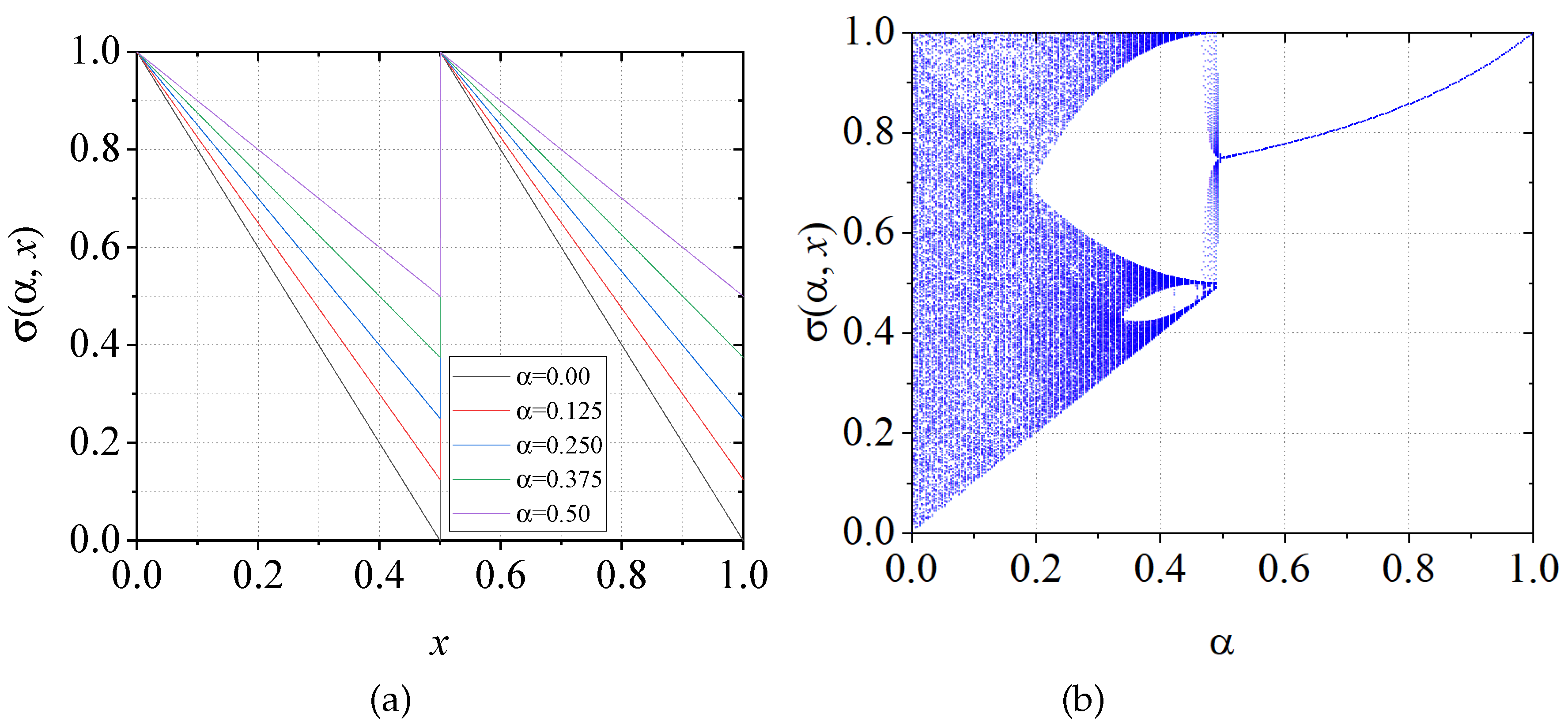
and can be visualized in
Figure 1a under different values of
, while its bifurcation diagram is shown in
Figure 1b. Note that the chaotic region does not cover the entire phase space.
2.1. Multiple MBCM
This section presents an approach to enhancing chaotic behavior by utilizing four distinct
MBCMs, with each chaotic map occupying a specific region within the phase space. Starting from Equation (
3), we apply function transformations to derive the following expressions:
As illustrated in Equations (
4), (
5), and (
6), each can be expressed in terms of Equation (
3). This implies that, with a single chaotic map, the chaotic behavior is primarily dispersed across the phase space. However, the structure of multiple
MBCM (
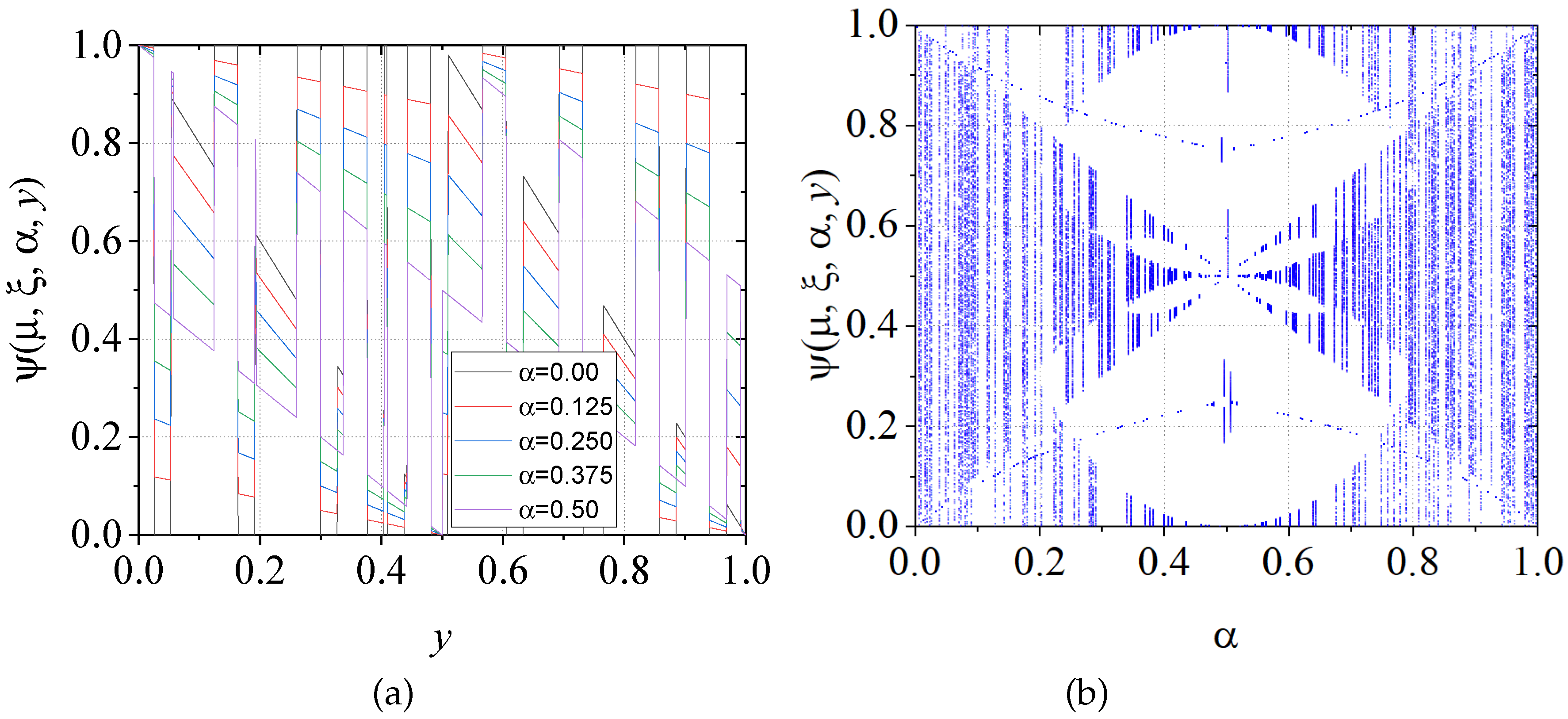
M-MBCMs) significantly increases the complexity and unpredictability of the chaotic sequences.
Figure 2 depicts the bifurcation diagram, demonstrating this enhanced chaotic behavior.
Equation (
7) represents the iterated version of the system composed of multiple
MBCMs, referred to as Multiple Modified Bernoulli Chaotic Maps (
M-MBCM). This system comprises a set of functions:
, each of which is randomly selected using the function
, where
is a control parameter in
, and
is an initial condition of the map in
. The variable
represents the system’s state at time
t, governed by the map selected by
, which dictates the evolution of
over time. At each iteration
t,
is computed using different maps
, chosen randomly based on
.
Additionally, serves as a control parameter that regulates the dynamics of the M-MBCM, specifically determining the range in which the various maps are applied. This parameter can be adjusted to influence the behavior of the maps across different regions of the phase space, thereby affecting the nature of the generated chaos. The selection process for is as follows: when , is selected; if , is chosen; if , is used; and when , the function is selected.
2.2. Sine Function and M-MBCM
As noted by [
33,
40,
41,
42], robust chaos is characterized by the absence of periodic windows and coexisting attractors across the entire chaotic range, maintaining its chaotic behavior despite small perturbations in parameters or initial conditions. A robust chaotic system should not lose its chaotic behavior or become periodic under such variations. To enhance numerical resolution of
, we apply a large scaling factor
A (in our case,
or higher precision) to increase the variability of chaotic orbits. The sine function is used to modulate or normalize the chaotic sequences to the range
. Applying the scaling factor and the sine function, we obtain:
where
represents the iteration step,
is the initial condition set,
is related to the selection of
MBCM,
is the control parameter,
is the initial
MBCM control parameter, and
. Equation (
3) operates within the limits
,
, and
. By combining the low-dimensional chaotic map with the sine function, we generate a low-dimensional robust chaotic map called the sine
M-MBCM (
SM-MBCM), as illustrated in
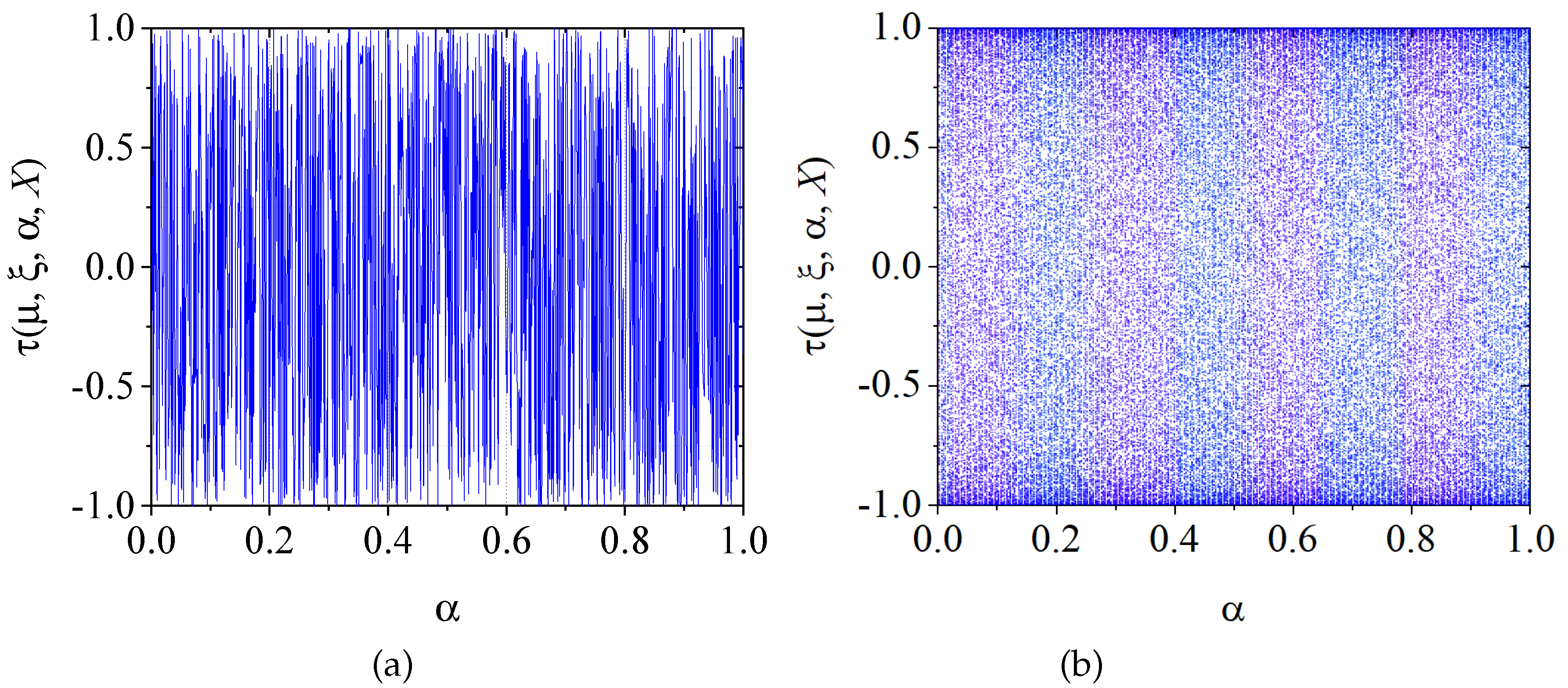
Figure 3.
Figure 3 highlights that the
SM-MBCM demonstrates greater sensitivity to initial conditions compared to the
M-MBCM (see
Figure 3a). Notably, the bifurcation diagram reveals the absence of stability islands and exhibits complex chaotic behavior across all parameter settings (
Figure 3b).
3. Behavior Analysis of the SM-MBCM
In dynamical systems, a fixed point satisfies
. Identifying fixed points is crucial, as they may indicate stable or unstable behaviors within the system. For the
SM-MBCM, we analyze the conditions that lead to the emergence of periodic sequences, as well as those that result in aperiodic sequences. First, we focus on determining the conditions that suppress chaotic behavior in the proposed Bernoulli maps. To find the fixed points, we must solve
for each
, where
and 4, and for each interval
,
,
, and
. These fixed points serve as a reference for identifying new fixed points defined for
SM-MBCM.
Table 1 shows the fixed points for each Bernoulli map.
Similarly, the analysis was extended to obtain second- and third-order fixed points. A second-order fixed point, denoted as
, must satisfy
. The expressions obtained for second-order fixed points are presented in
Table 2. Additionally, for a third-order fixed point, denoted as
, the function applied three times must satisfy
. The expressions derived for
is shown in
Table 3.
The identification of fixed points enables a more comprehensive understanding of the system’s behavior under varying conditions, facilitating the identification of regions where the system may exhibit periodic or chaotic behavior. In dynamic systems, identifying higher-order fixed points provides insight into the system’s capacity to generate periodic sequences of varying lengths. To illustrate, second- and third-order fixed points indicate that after two or three iterations, the system returns to the same value, suggesting cycles of period two or three. These cycles are essential for grasping the structure of the SM-MBCM and its prospective applications. In order to obtain the fixed points of the SM-MBCM function, we applied numerical methods using Mathematica’s
FindRoot function, subject to the following criteria. We began by evaluating and identifying subsequent fixed points using the first-, second-, and third-order expressions as a starting point. In the evaluation, we considered the first 50 fixed points with different values of A within each interval defined by
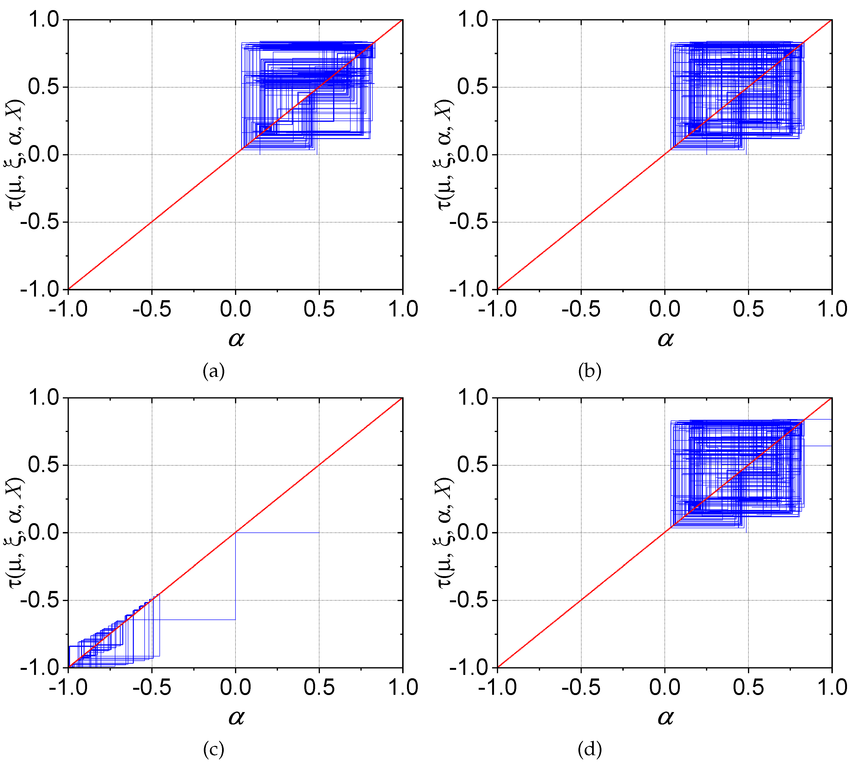
. To test each fixed point, 300 iterations were completed and the resulting chaotic sequences were plotted.
Figure 4 illustrates the behavior of the 50 fixed points under the following conditions: (a)
and
; (b)
and
; (c) The next set of conditions to be considered is as follows: (a)
and
; (b)
and
. It should be noted that
Figure 4 depicts a fixed point selected from a specific Bernoulli chaotic map, but the subsequent evolution is not shown. In subsequent iterations of the function
, a different chaotic map may be selected, which may not necessarily take the same fixed point into account. This results in a loss of continuity, which in turn means that the evolution of the initial fixed point cannot be observed; instead, a set of discontinuous fixed points emerges.
Similarly, the results can be verified by generating a trajectory diagram of the
SM-MBCM for different values of
A over 300 iterations.
Figure 5a depicts the trajectory diagram for
with
.
Figure 5b demonstrates consistent results for
with
.
Figure 5c demonstrates comparable behavior to the previous cases, but for
and
.
Figure 5d illustrates the trajectory for
and
. It should be noted that the fixed points are confined to a limited area in phase space. As a result, it is not possible to observe the evolution of the initial fixed point, and instead, a set of discontinuous fixed points appears. Consequently, the development of chaotic behavior in the
SM-MBCM remains inconclusive.
In contrast, considering a large value of
A of about
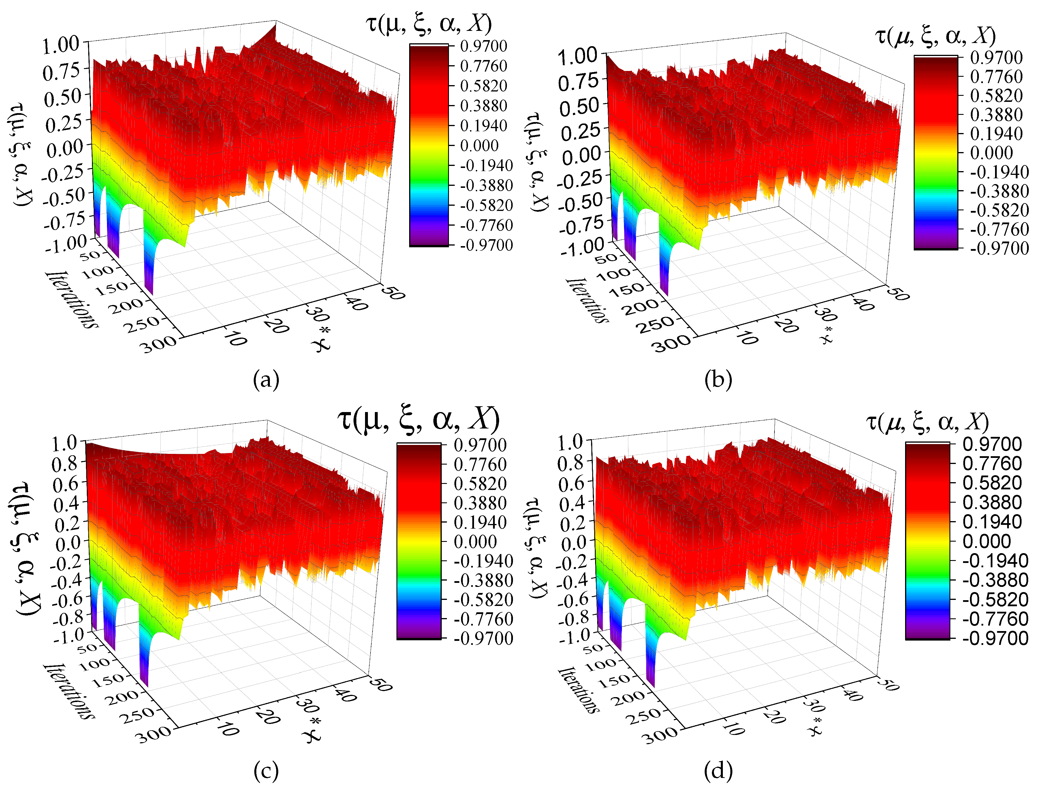
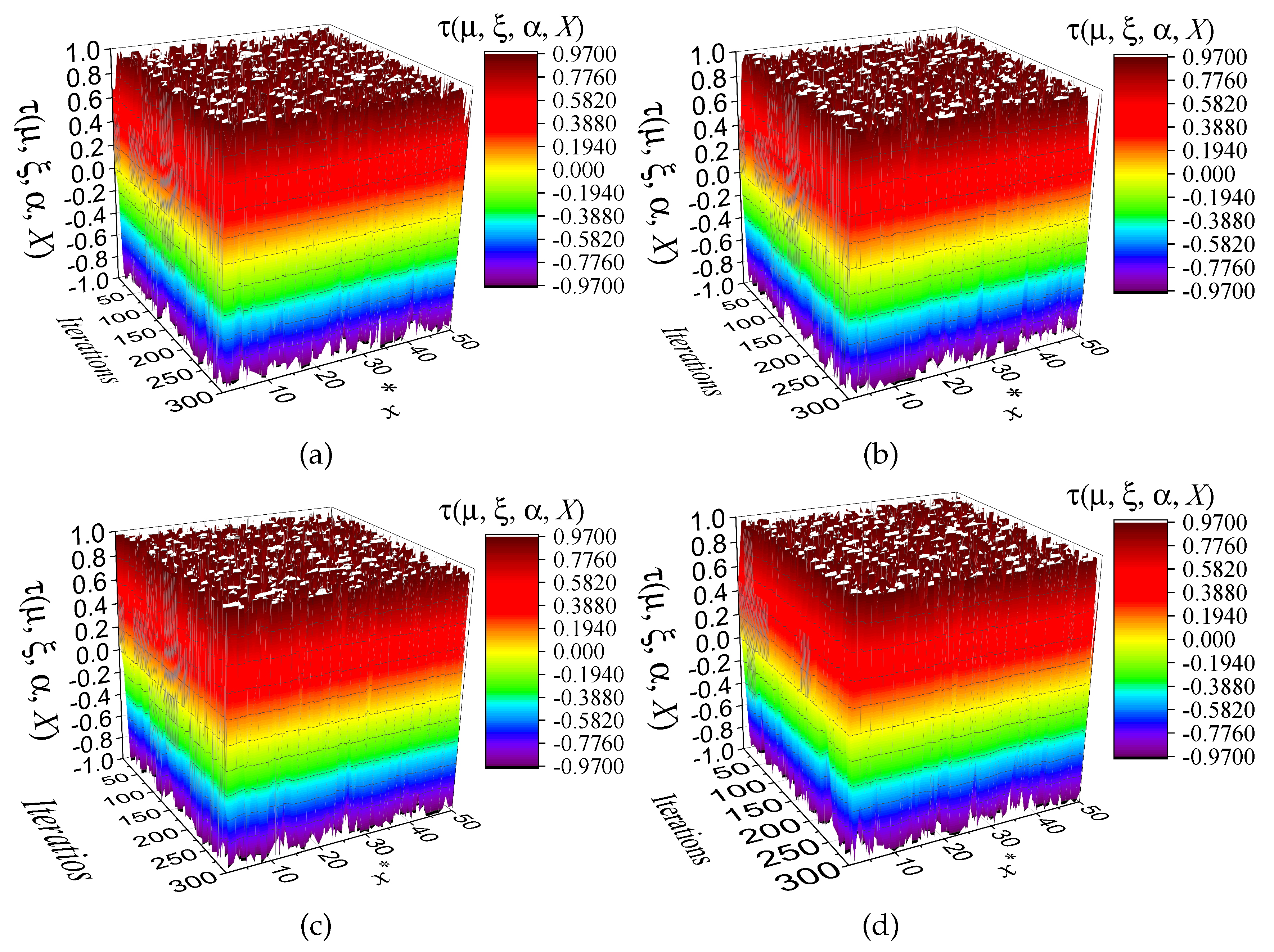
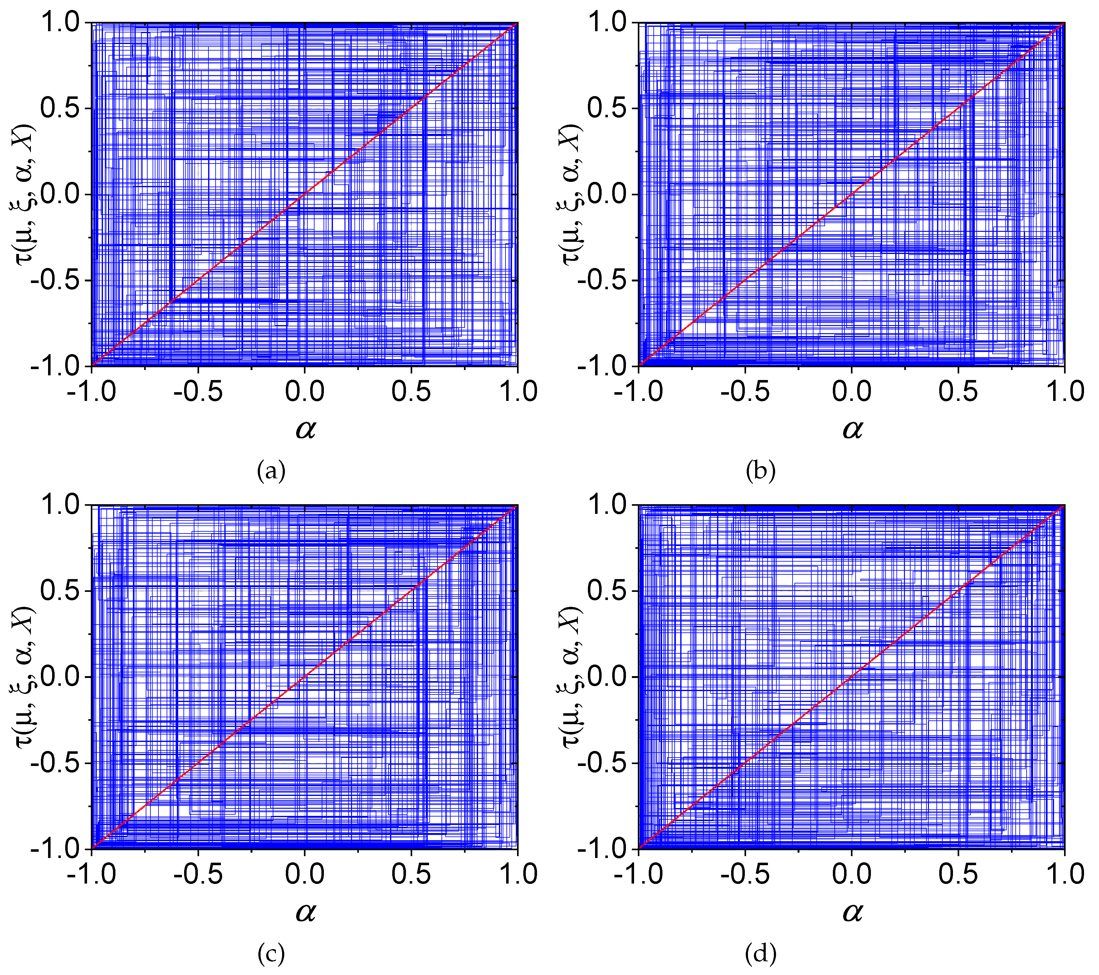
or higher precision generates number chaotic sequences with better properties. We have considered the same 50 initial conditions, each iterated 300 times. It can be observed in
Figure 6 that the chaotic orbits appear within the interval -1 to 1. This indicates a substantially evolved chaotic behavior over 300 iterations using an ensemble of 50 initial conditions. Similarly, as shown in
Figure 7, a comparable result can be seen in the trajectory plots, where a fully developed phase space is observed after 300 iterations, with initial values of
= 0.1,
= 0.25,
= 0.75 and
= 0.99 corresponding to panels (a), (b), (c) and (d), respectively.
3.1. Sensitivity Analysis of SM-MBCM
In the analysis of chaotic systems, the Lyapunov exponent serves as a key metric for quantifying the system’s sensitivity to initial conditions. It specifically measures the rate at which nearby trajectories in phase space diverge over time. A positive Lyapunov exponent indicates chaos, as it reflects the exponential divergence of initially close states, resulting in unpredictable long-term behavior. For the function under consideration, defined as:
In this section, we derive an expression for the Lyapunov exponent.
represents the
i-th iteration of the map, while the function
encapsulates the dynamics of the Bernoulli map, incorporating essential parameters such as
,
,
, and
that govern the system’s behavior. This expression provides a basis for analyzing the system’s sensitivity to initial conditions and its resulting chaotic evolution. To compute the Lyapunov exponent, we considered the distance between two initially close points in phase space, denoted as
and
. The difference in their mapped values after one iteration is given by Equation (
10).
where
is a small perturbation in the initial condition. Using the trigonometric identity for the difference of sines:
, we can express the difference as:
where
. Given that
is small, we can expand
around
using a Taylor series expansion.
Substituting this into the sine difference:
The Lyapunov exponent
is defined as:
For the given system, the derivative
corresponds to:
This expression represents the Lyapunov exponent for the system described by the iterated function
, which captures the dynamics of the
M-MBCM. A positive value of
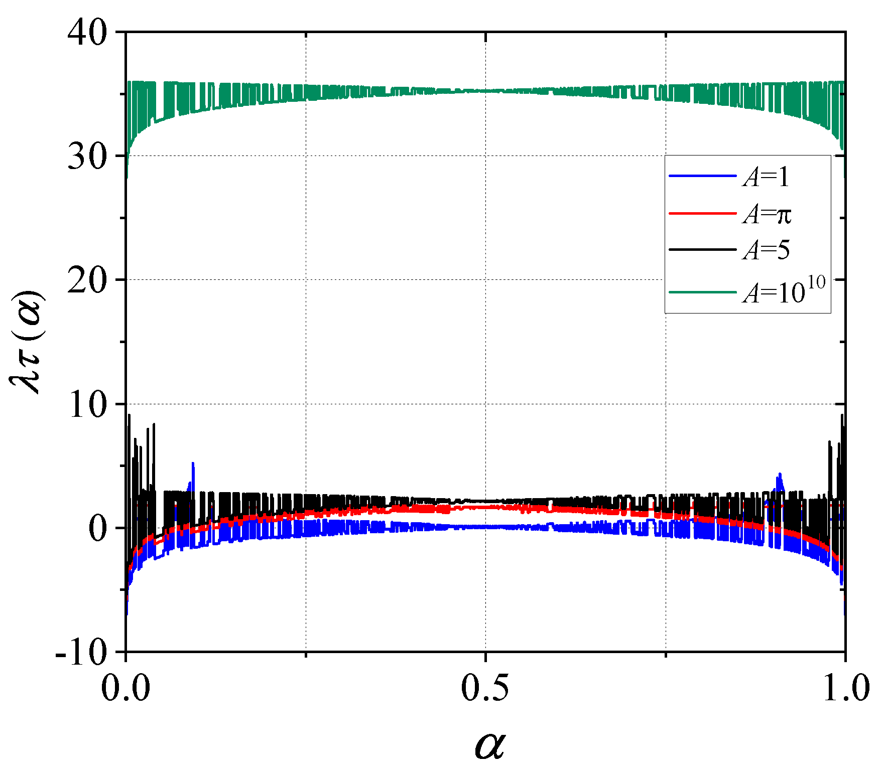
consequently indicates chaotic behavior, where small differences in initial conditions result in an exponential divergence of trajectories in phase space. As shown in
Figure 8, for lower values of
A, the Lyapunov exponent remains near zero or even negative. However, with larger values of the scaling factor
A, the amplitude of variations in the chaotic system
SM-MBCM increases. This leads to heightened sensitivity to small perturbations, which are rapidly amplified due to the increasing frequency and amplitude of the
sin function oscillations. Such behavior is characteristic of highly chaotic systems, where the exponential growth of initial differences becomes more pronounced as
A increases.
4. CPRNG Based on SM-MBCM
According to various statistical mechanics tests, the
SM-MBCM demonstrates high complexity and supports a wide range of chaotic behaviors within the interval (
). Furthermore, increasing the scaling factor
A significantly amplifies the small variations inherent in the system. As the value of
A grows, even minor changes exert a greater influence on the chaotic behavior of the
SM-MBCM, as confirmed in
Section 3. Consequently, the chaotic pseudo-random number generator (
CPRNG) leverages the
SM-MBCM, with outputs scaled via 32-bit modular multiplication.
Algorithm 1 illustrates the integration of a single MBCM to represent the execution of four MBCMs using . The pseudo-random function generates to determine the selection of with varying values of . The float2fixed function converts X from a 64-bit floating-point format to a fixed-point format. Additionally, a scaling factor B with a value of is applied. The selection criterion for is defined as follows: for , is selected; for , is chosen; if , is used; and for , is selected.
The product of
B and
X generates large angles, which must be reduced to the range
using the
function in
format. The
function calculates the sine using the Coordinate Rotation Digital Computer (CORDIC) algorithm in
fixed-point format. The updated value of
X is then converted back to a 64-bit floating-point format for further evaluation. Finally,
K is obtained through the
operation in 64-bit fixed-point format.
|
Algorithm 1:CPRNG based on SM-MBCM. |
|
function [K] ← SM-MBCM(, , , X, n)
- 1:
A←
- 2:
B←
- 3:
, PI_BY_2_val]← Q54.10 Format - 4:
- 5:
i ← 1 - 6:
while i ≤ n do
- 7:
(, ) Pseudorandom function - 8:
if 0.0) and then
- 9:
() and () - 10:
) () and () - 11:
- 12:
else
- 13:
- 14:
end if
- 15:
- 16:
- 17:
IEE-754 Format - 18:
- 19:
end whilereturn (K)
end
|
5. Testing of the Proposed CPRNG
For the statistical tests of the chaotic sequences generated by the proposed , we performed an ensemble of 1000 initial conditions . For each , we applied with and . In each sequence, we obtained , where . Using these number chaotic sequences, the following tests were conducted: correlation coefficient, key sensitivity, entropy, statistical analysis, randomness, and linear complexity. Additionally, we estimated the key space and evaluated the computational complexity.
5.1. Correlation Coefficient
The correlation coefficient (
r) is a crucial metric for assessing the quality and uniformity of a generated number sequence. If a
PRNG produces correlated numbers, it indicates that the numbers are not evenly distributed and may exhibit discernible patterns or biases. In accordance with Equation (
16), the correlation coefficient
is defined as:
Here,
and
represent the
th values of the compared number sequences, while
and
represent the mean values of
and
, respectively.
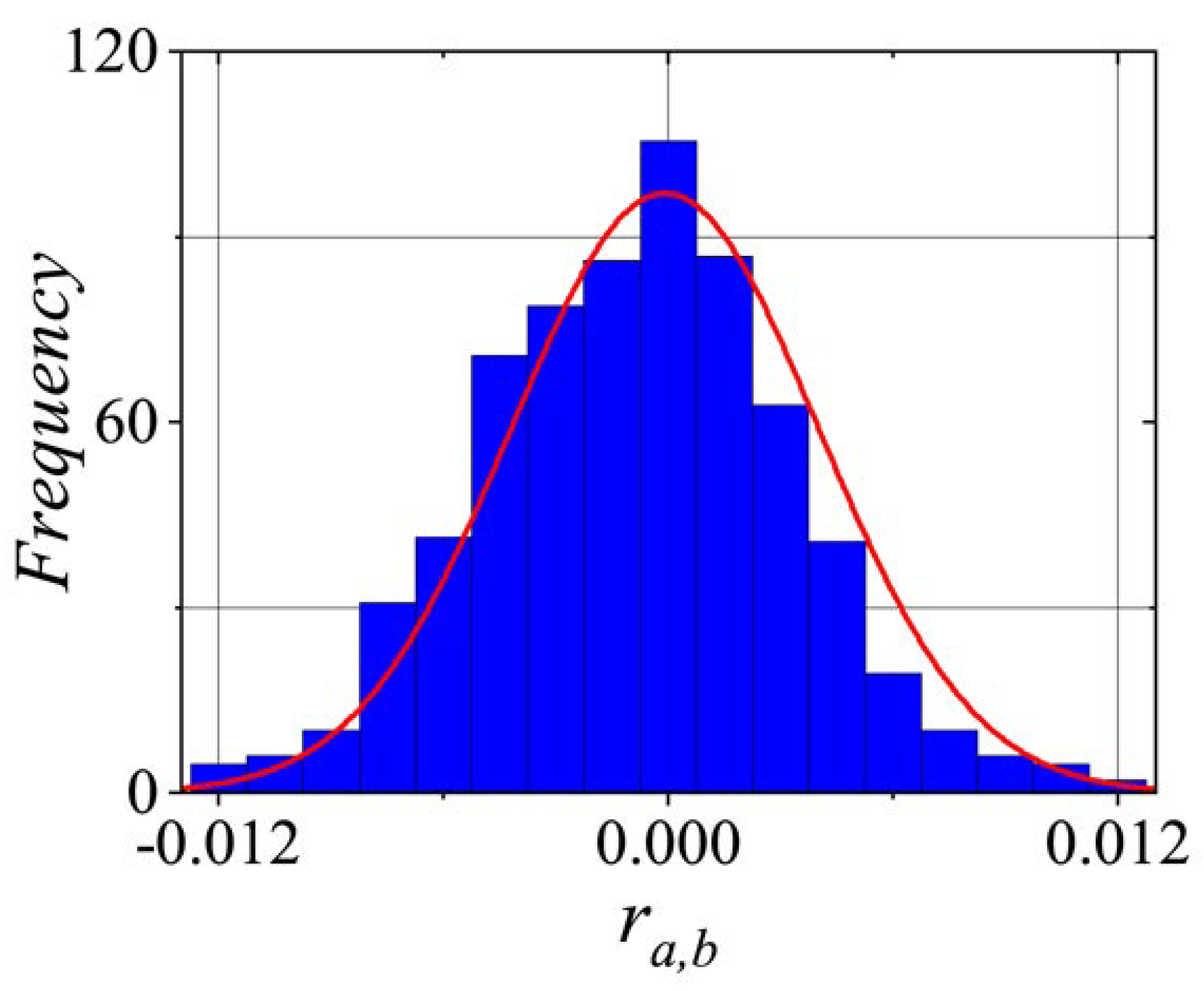
Figure 9 illustrates the statistical distribution of the correlation coefficient
r when
, with both indices ranging from 1 to 1000.
A correlation coefficient close to 1 indicates a strong positive correlation, meaning that the two variables tend to increase or decrease together. In contrast, a value close to -1 suggests a strong negative correlation, where one variable increases as the other decreases. A coefficient close to 0 indicates the absence of a significant linear relationship between the variables. As seen in
Figure 9,
r is distributed in
, and it only measures the linear relationship between two variables and cannot detect more complex patterns in the pseudorandom number sequence. Therefore, additional statistical and graphical tests are necessary for a more comprehensive evaluation of the
PRNG’s quality.
5.2. Key Sensitivity
The number pixel changes rate (
NPCR) and unified average changing intensity (
UACI) tests are methods used to evaluate the randomness of a
PRNG. The
NPCR is calculated as the percentage of numbers in a sequence that differ from their preceding number. A high
NPCR value (90% or higher) suggests strong randomness, as it indicates a substantial number of distinct values within the sequence. The
UACI measures the average difference between consecutive numbers in the sequence. A high
UACI value (33% or higher) also signifies randomness, as it reflects significant variation between consecutive numbers. For these tests, we select a set of 1000 keys (
K), with only slight variations between them. A small change of
was applied to the least significant bit, and then 1000 sequences of pseudorandom numbers were generated, denoted as
, where
. Each sequence consisted of 31250 32-bit numbers. The
NPCR and
UACI are mathematically defined as follows:
where,
The
UACI is represented by,
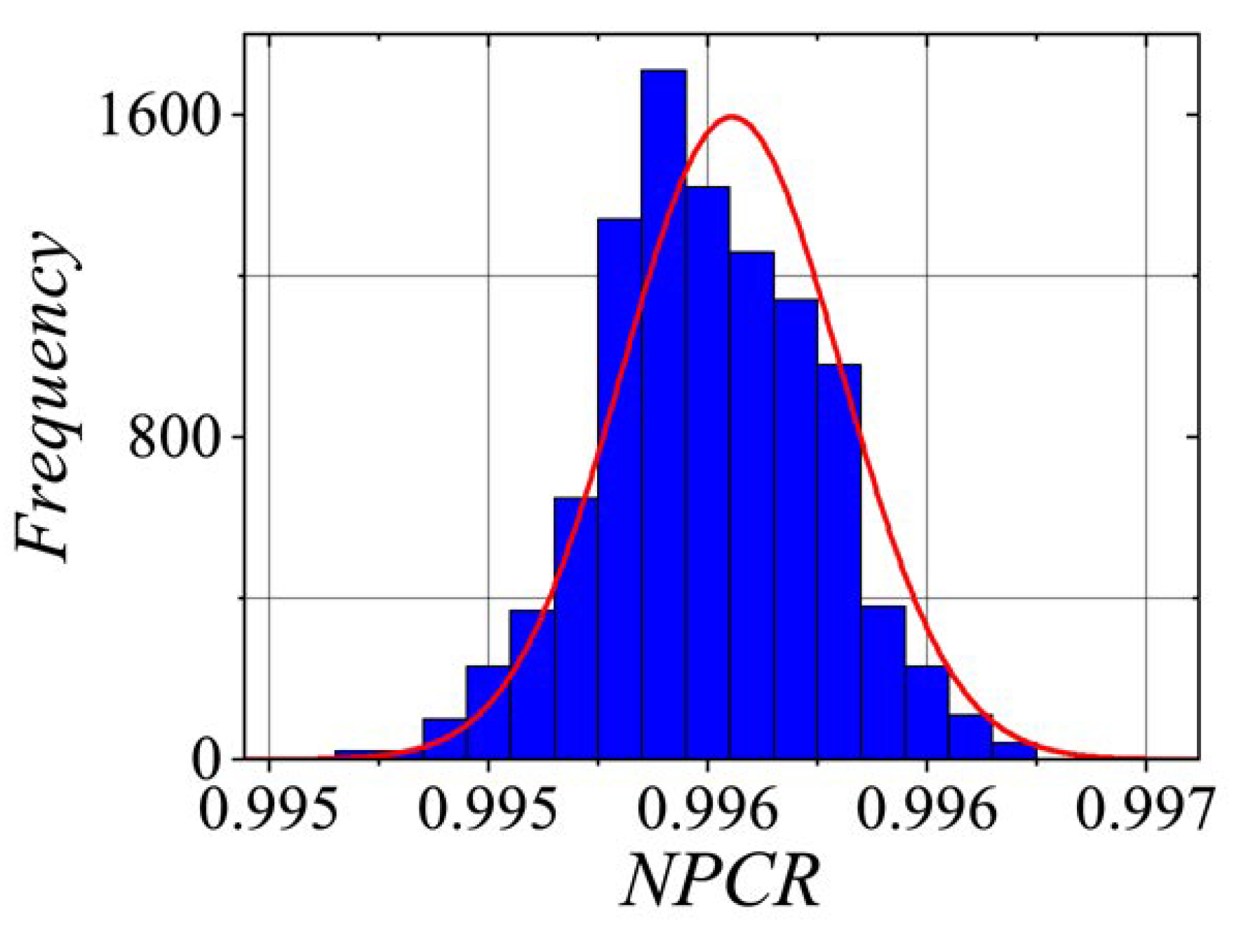
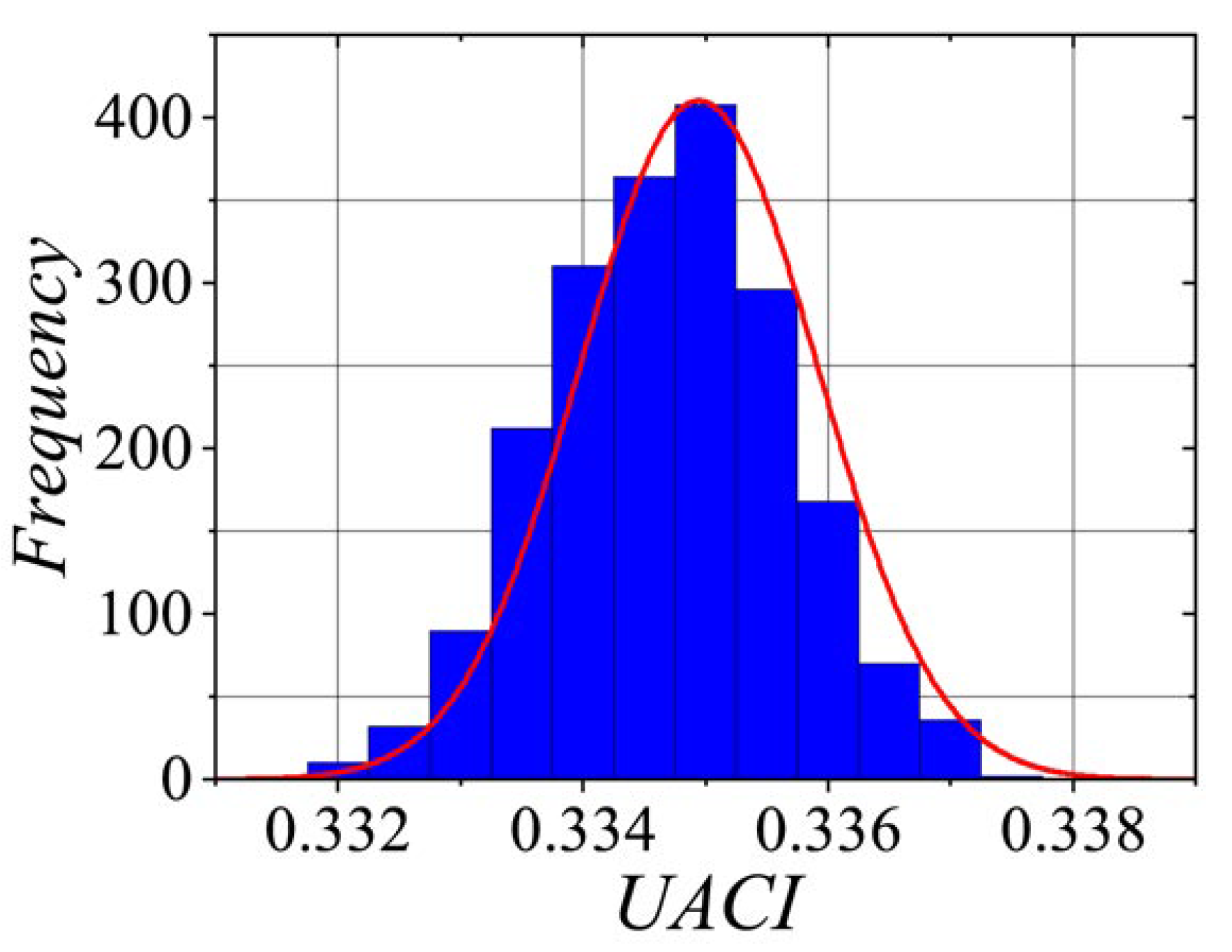
Figure 10 and
Figure 11 illustrate the statistical distributions for
and
, respectively. It is worth noting that the
values fall approximately within the range
, while the
values lie within
. The average absolute difference (
AAD) is another metric used to assess the randomness of a
PRNG. It was calculated as the mean of the absolute differences between consecutive numbers in the sequence.
A high
AAD value suggests randomness, as it indicates significant variation between consecutive numbers. Conversely, a low
AAD value implies that the sequence lacks randomness, with minimal differences between consecutive numbers. The
AAD can be mathematically defined as follows:
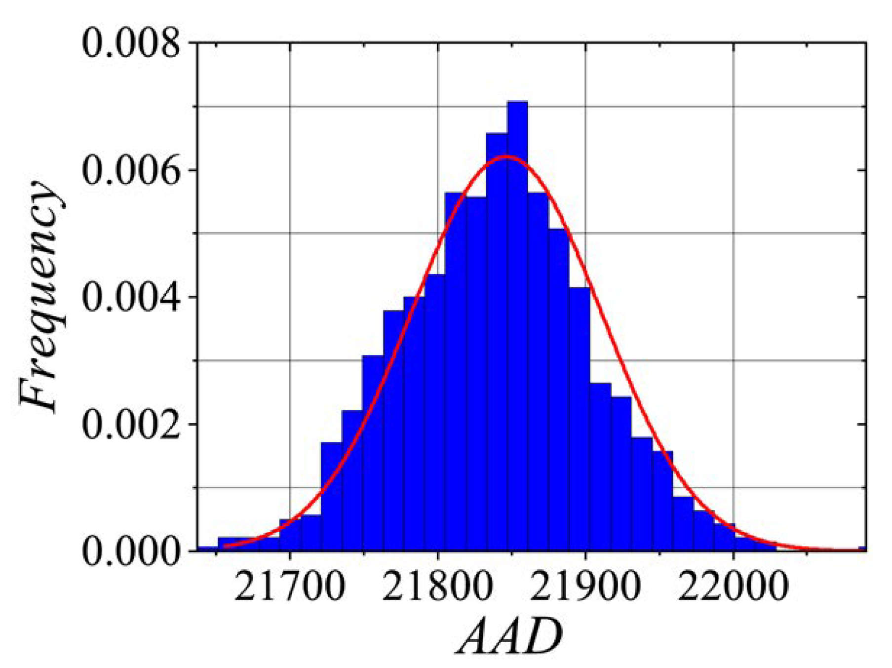
It is worth noting that the results were [21700, 22000] (see
Figure 12). These results are very similar to those reported by Palacios-Luengas et al. [
43].
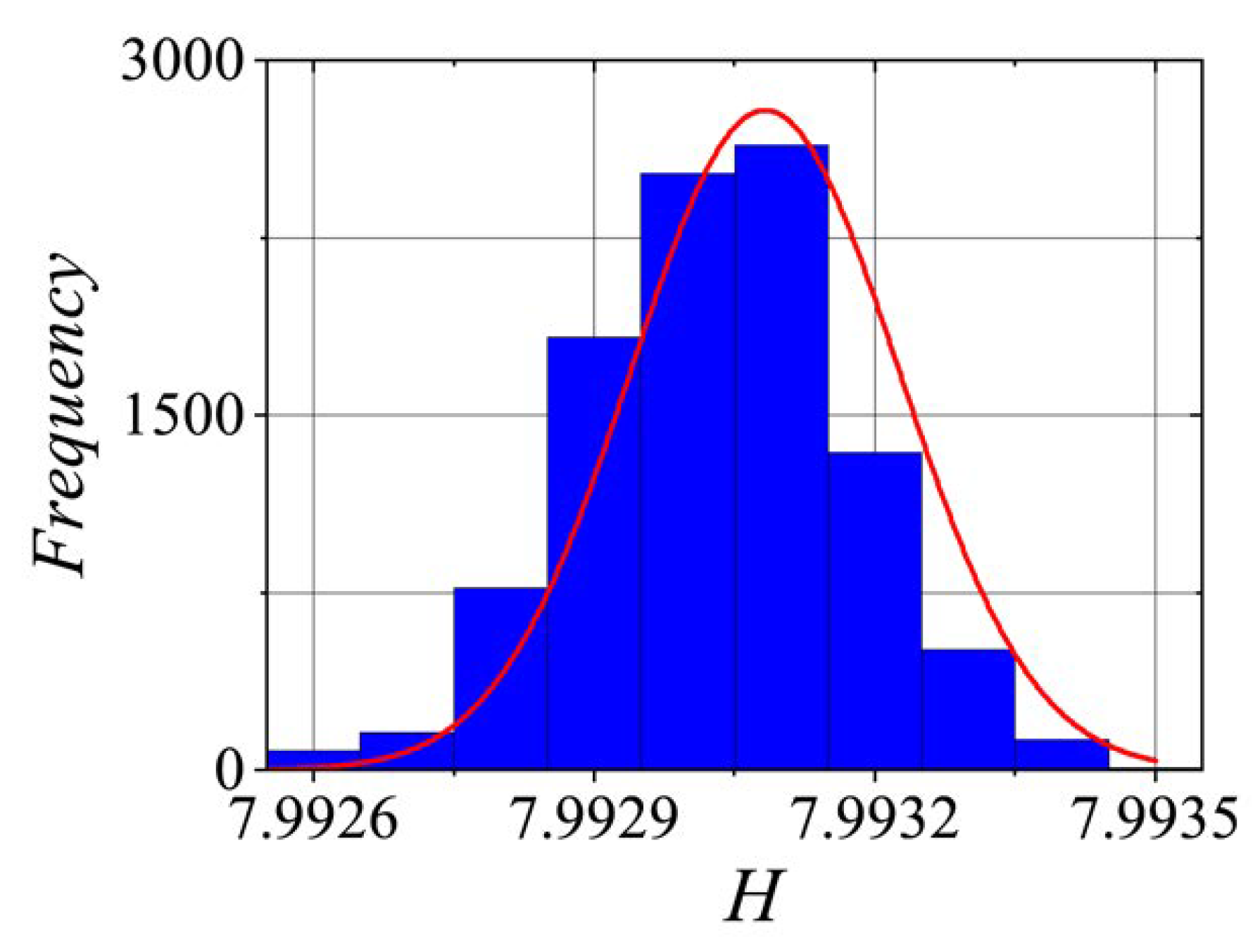
5.3. Entropy Analysis
The entropy value
H, measured in bits, represents the amount of information per bit in the generated number sequence. A high
H value indicates that the number sequence has high entropy and is more unpredictable, which is desirable in a
PRNG. Conversely, a low
H value suggests that the number may exhibit patterns and be less random. Equation (
21) represents Shannon’s entropy:
where
denotes the estimated probability of each
, with
, and each sequence consisting of 125000 8-bit numbers; it is worth noting that the entropy in
Figure 13 ranges into
, which is very close to the ideal value of 8.
5.4. Statistical Evaluation and Assessments of Randomness
To validate our proposed chaotic pseudorandom number generator (
CPRNG), we employed two statistical tests for randomness: The National Institute of Standards and Technology (NIST) Special Publication 800-22 [
44] and TestU01 [
45]. The tests were conducted on a 64-bit Ubuntu operating system with an Intel Core i5 7200U processor and 16 GB of RAM. In the NIST SP 800-22 suite, we determined the proportion of number sequences that passed the test for each configuration of our
CPRNG. We then calculated the confidence interval for each configuration using the following formula:
, where
is the proportion of number sequences that passed the test and
m is the number of sequences generated. In our case, we used
number sequences and
, resulting in a confidence interval of
.
For NIST sub-tests that consider multiple
, we selected the minimum value. The results of these tests are presented in
Table 4, showing that our
CPRNG passed all statistical tests for randomness. This confirms that it is a high-quality pseudorandom number generator, suitable for a wide range of applications.
The TestU01 test suite is a software library implemented in C that offers a set of tools for empirically and statistically testing random number generators (
RNG) and pseudorandom number generators (
PRNG). TestU01 provides three levels of tests: SmallCrush (15 tests), Crush (144 tests), and BigCrush (160 tests). Additionally, it includes the PseudoDIEHARD battery of tests, which applies most of the tests from the well-known DIEHARD suite by Marsaglia (1996) [
46]. The Alphabit, Rabbit, and BlockAlphabit tests, also part of TestU01, are specifically designed to evaluate bit generators implemented in hardware.
According to NIST standards, a test is considered successful if its
P-value lies between
and
.
Table 5 presents the successful results of the proposed
CPRNG when generating 32-bit number sequences of lengths
,
, and
. In the BigCrush test, our
CPRNG failed the Coupon Collector problem; however, using alternative seed values, the sequences generated by the proposed PRNG can pass all tests.
5.5. Linear Complexity
The linear complexity (
L) of a
PRNG is a measure of its efficiency. To estimate the linear complexity, we use the Berlekamp-Massey algorithm to calculate
for the pseudorandom sequences generated by the proposed
PRNG. This allows us to determine the generator polynomial capable of producing the pseudorandom sequences from our
CPRNG. For this test, we generated 1000
K values with small variations between them. These values were used to generate 100000 bits. Let
represent a sequence of pseudorandom numbers. We define
and
. For each
, we calculate
, where
is the lowest degree coefficient of
. The generator polynomial is then represented by
.
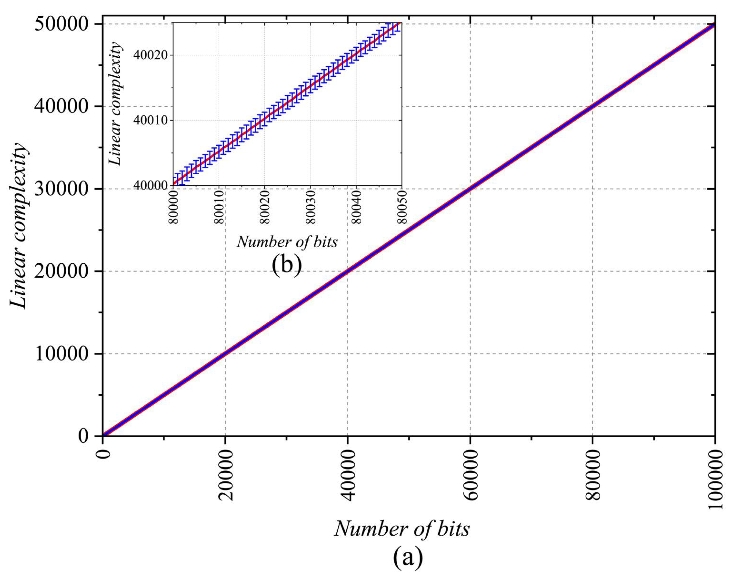
Figure 14 presents the mean and standard deviation of
for the 100000 sequences. As shown, the linear complexity reaches a maximum level at approximately
, and the variation in standard deviation values is minimal. This confirms that the methods implemented in the
CPRNG successfully increase linear complexity, mitigating the issues commonly encountered in
PRNG based on a single chaotic map.
5.6. Key Space Estimation
This analysis is an integral part to the security assessment, as outlined by Kerckhoffs’ principle. This principle specifies that the security of a cryptographic system should remain intact even if all aspects of the system are publicly known, except for the key. In line with this, the security of the proposed CPRNG is tied to the size of the key space required to generate numerical sequences.
Assuming the proposed CPRNG is a cryptographic module with publicly available details, its security relies solely on the key used to produce pseudorandom sequences. Therefore, the CPRNG must offer a sufficiently large key space to effectively resist brute force attacks. As shown in algorithm 1, the key comprises parameters , , , and . Considering a standard double-precision floating-point format, the CPRNG key has 256 bits, providing a global key space of values, which meets the general requirement for resistance against brute force attacks. To avoid fixed point conditions, the scaling factor A was selected as .
5.7. Algorithmic Complexity of Proposed CPRNG
To determine the computational complexity of the proposed CPRNG, the basic operations defined in Algorithm 1 were identified. The algorithm performs arithmetic operations, logical operations, and function calls. The arithmetic operations include addition, subtraction, multiplication, and division. The algorithm calls the function , which has an algorithmic complexity of since it only performs a comparison and a multiplication. The function also has an algorithmic complexity of , as it only involves a comparison and a multiplication. Therefore, the overall complexity of the algorithm is .
The function cordicsin uses the Coordinate Rotation Digital Computer (CORDIC) algorithm, which generally has a complexity of , where R is the number of iterations needed to achieve the desired precision. In practical implementations of CORDIC, R is typically a small constant, making the complexity approximately . The AngleReducer function reduces the angle to , which also has a complexity of , as it usually involves only a few comparisons and calculations.
This means that the execution time of the code remains constant, regardless of the size of the input data. The mod(X ) operation involves a multiplication and a module operation, both of which have a constant complexity of . The float2fixed and fixed2float functions perform the necessary conversions, each following a constant-time operation for fixed-size or floating-point numbers, thus having a complexity of .
Finally, within the while loop, several if-else statements are executed, but each branch involves a constant number of arithmetic operations and function calls with complexity. As a result, the complexity of an individual iteration of the loop is . The while loop runs n times, where n is the input parameter. Since each iteration has a complexity of , the total complexity of the loop is . Then, the computational complexity of the CPRNG based on Bernoulli maps and the sine function (CORDIC), is linear with respect to the pseudorandom number generated. This means that the time required to execute the algorithm increases proportionally with n. To validate the above analysis, Algorithm 1 was implemented in the C language, and to obtain the average execution time, 1000 runs were performed, yielding an average of 0.194 s. The program’s performance is approximately 131.5 Mbps.
6. FPGA Implementation of the CPRNG
In the hardware implementation of the proposed
CPRNG with low resource requirements, we utilized the Basys 3 board, featuring the Artix
XC7A35TCPG236-1 Field Programmable Gate Array (FPGA), and VIVADO 2024. Based on the Algorithm 1, the following components were used to represent the
CPRNG in hardware: The function
was defined as
, which is associated with the Skew Tent Map (STM) chaotic map as the random function. The
block is linked to the
, where the output orbit was scaled by factor
A, and subsequently converted to a Q54.10 fixed-point format. Next, an angle reduction is performed to adjust the output within the range
, with a final output in
format. The
instance, based on the CORDIC architecture, evaluates and produces the result in
format. Finally, a scaling process is applied using a factor of
, and the resulting cipher sequence is represented in 32 bits through a modulo
operation. The output from the
instance is then converted to floating-point using
and fed-back into the
MBCM block.
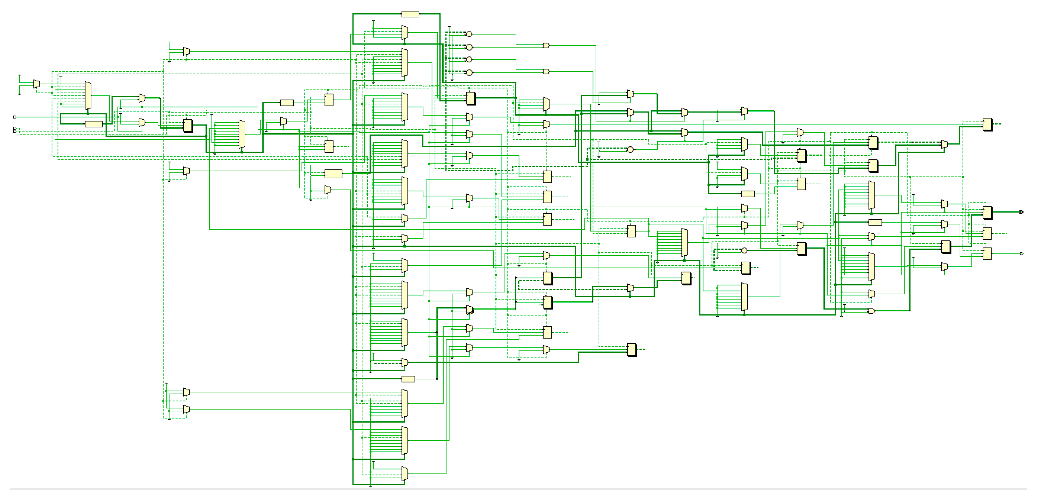
Figure 15 illustrates the functional blocks that represent the proposed
CPRNG. According to the implementation characteristics, the FPGA can operate at a clock frequency of up to
.
The execution of the proposed system, based on simulations, takes approximately 7 clock cycles (see
Figure 16).
Table 6 shows the resource consumption in this design. It can be observed that
of the LUTs were used, with an estimate of 2406 out of 20800 utilized. For FFs, the estimate was
, with 880 out of 41600 used. Regarding DSP blocks, the utilization was
, i.e., 3 out of 90 used. Finally, for BUFGs,
were used, which corresponds to 1 out of 32 available.
6.1. Comparison of the Proposed CPRNG with the FPGA Implementations of Chaos-Based PRNGs
It is not possible to directly compare the execution of our
CPRNG with others reported in the literature due to several reasons. No similar strategy exists to the one proposed in this study, where the Bernoulli chaotic map was evaluated in different areas of the phase plane by changing its control parameter
and using a scaling factor
A. However, some comparable elements can be considered: key space, throughput, word length generated per iteration, and clock frequency.
Table 7 presents this information, where it can be observed that our
CPRNG performs well compared to others.
7. Discussion
The results of this study show that by applying a scaling factor of
or greater, the chaotic behavior becomes more pronounced, amplifying even small changes. Moreover, the random selection
of each Bernoulli chaotic map enhances the dispersion of chaotic orbits, resulting in improved statistical properties. The sine function acts as a modular operation that confines these scaled chaotic orbits within
. In this regard, obtaining the fixed points of the
SM-MBCM becomes difficult. This is because a fixed point obtained from one Bernoulli map,
, does not correspond to a fixed point of
or
, or even
. Therefore, when a fixed point is selected from one of the Bernoulli chaotic maps, the function
may choose another function, leading to a loss of continuity in the evolution of the initial fixed point. As a result, periodicity is observed in the evolution of the fixed point, and it becomes difficult to clearly observe the convergence of these points, as shown in
Figure 4 and
Figure 5. Another key point is that no fixed points are obtained when
or higher precision is used. According to Mathematica, greater precision is required to obtain any fixed points. Consequently, the strength of our scheme lies in considering a very large
A and using a random or pseudorandom function that mixes the selection of Bernoulli chaotic maps. In our results, we assume that the function
is ideal and does not consider the existence of fixed points. However, this aspect is beyond the scope of our analysis. For the electronic implementation, we employed the skew tent map (STM), which, according to Palacios-Luengas [
43], includes fixed points. Therefore, to improve the results, we recommend using a more complex function that does not account for fixed points.
Regarding the key space, our system covers a key space of approximately values, which is suitable for current security requirements in devices. If it is necessary to expand this key space, it can be achieved by introducing a control parameter and an individual initial condition for each map representation. Consequently, the key space could be quadrupled if a precision of 64 bits is considered.
In terms of electronic implementation, it is evident that to achieve a better representation of the system, IEEE-754 floating-point operations must be used, which are challenging to synthesize in most hardware description languages. Therefore, specific solutions are required for VHDL. In our case, we utilized several blocks, one of the most significant being the conversion from floating-point to fixed-point. To validate the system’s operation, statistical tests were conducted using a C language representation, considering each of the tests evaluated in this study. Additionally, we considered using Vitis HLS as an alternative to facilitate the programming of the proposed system.
Finally, we believe that this scheme for generating pseudo-random sequences with good statistical properties could be useful in systems with memory limitations, such as microcontrollers for IoT devices. It could also be applied in schemes that require the generation of cryptographic keys to be used as session keys.
8. Conclusions
In this study, we proposed a chaotic pseudo-random number generator (CPRNG) based on a modification of the Bernoulli chaotic map (MBCM), designed to evaluate distinct regions of the phase space [0, 1] through its control parameter . As a result, multiple modified Bernoulli chaotic maps were considered, each operating in different regions of the phase space according to the value of . To further enhance the dispersion of the chaotic number sequences, a pseudo-random function was used to select the chaotic map based on a defined control parameter . This method increased the spread of chaotic orbits, enabling broader coverage of the phase space. However, this alone was insufficient, as regions of stability still persisted and the Lyapunov exponent remained in areas with values less than zero.
To further increase the sensitivity of the chaotic orbits produced by the MBCM, they were scaled by a factor A of . Applying the sine function to the amplified chaotic orbits enhance their chaotic properties. This improvement was validated through bifurcation diagrams, chaotic orbit series, phase diagrams, and Lyapunov exponent analysis. Consequently, we developed a set of Bernoulli maps that generate chaotic sequences within , referred to as the SM-MBCM.
To validate the system, we employed various statistical mechanics tools and proposed a CPRNG with its implementation in VHDL. To optimize digital resources, we focused on a single modified Bernoulli map, deriving equivalent values for the control parameters and . Based on these parameters, a single MBCM was defined, with the value of chosen according to . For the random function, we used a skew tent map (STM) to generate the values of . These chaotic maps, together with the scaling factor A, were implemented using 64-bit double-precision floating-point arithmetic. The conversion from floating-point to 64-bit fixed-point format enables angle reduction to the range to , facilitating the angle evaluation in CORDIC using the Q3.45 format. Due to the feedback from the sine output, we also developed a conversion from Q2.46 to 64-bit floating-point.
According to the analysis, some degradation in the chaotic orbits was observed due to the conversions performed. However, adjusting the scaling factor preserved the high dispersion and randomness of the 32-bit pseudo-random numbers generated at each iteration. This was verified through a series of evaluations. For these tests, we developed a similar version of the system in C and assessed the resulting number sequences. Using the TestU01 suite, we used the BigCrush, Alphabit, and Rabbit tests. Notably, the proposed 32-bit CPRNG passed nearly all tests, except for one. For the NIST tests, 2000 randomly selected keys (initial conditions) were used to generate 2000 pseudo-random sequences, each containing 1000000 bits. All results fell within the confidence interval.
Author Contributions
Conceptualization, L.P.-L. and R.V.-M.; methodology, R.M.-J. and R.C.M.-R.; software-hardware, L.P.-L.; validation, R.C.-J., E.R.-C. and F.R.M.P.-C.; formal analysis, L.P.-L. and R.V.-M.; investigation, L.P.-L. and F.R.M.P.-C.; resources, all authors; data curation, R.M.-J., E.R.-C. and R.C.M.-R.; writing—original draft preparation, L.P.-L. and R.V.-M.; writing—review and editing, R.V.-M., R.C.M.-R., F.R.C.-S, and R.M.-J.; visualization, F.R.C.-S. and R.C.M.-R.; supervision, L.P.-L.; project administration, L.P.-L.; funding acquisition, L. P.-L. and R.V.-M. All authors have read and agreed to the published version of the manuscript.
Funding
This research was supported by funding from the Autonomous Metropolitan University-Iztapalapa, under Project No. 12704013 (L. Palacios-Luengas), and from the Instituto Politécnico Nacional under project SIP-20240745 (R. Vázquez-Medina).
Informed Consent Statement
This article does not include any research involving human participants or animals conducted by the authors.
Data Availability Statement
The data that supports the findings of this study are available within the article.
Acknowledgments
The authors express their gratitude to Professor M. López-Villaseñor for his assistance in providing the Xilinx Basys-3 board.
Conflicts of Interest
The authors declare no conflicts of interest.
References
- Belazi, A.; Talha, M.; Kharbech, S.; Xiang, W. Novel medical image encryption scheme based on chaos and DNA encoding 2019. [CrossRef]
- Soni, R.; Thukral, M.K.; Kanwar, N. A relative investigation of one-dimensional chaotic maps intended for light-weight cryptography in smart grid. e-Prime - Advances in Electrical Engineering, Electronics and Energy 2024, 7, 100421. [Google Scholar] [CrossRef]
- Hematpour, N.; Ahadpour, S.; Sourkhani, I.G.; Sani, R.H. A new steganographic algorithm based on coupled chaotic maps and a new chaotic S-box 2022. [CrossRef]
- Meshram, C.; Ibrahim, R.; Meshram, S.G.; Imoize, A.L.; Jamal, S.S.; Barve, S.K. An efficient remote user authentication with key agreement procedure based on convolution-Chebyshev chaotic maps using biometric 2022. [CrossRef]
- Murillo-Escobar, D.; Murillo-Escobar, M.A.; Cruz-Hernández, C.; Arellano-Delgado, A.; López-Gutiérrez, R. Pseudorandom number generator based on novel 2D Henon-Sine hyperchaotic map with microcontroller implementation 2022. [CrossRef]
- Li, S.; Lin, Z.; Yang, Y.; Ning, R. A high-performance FPGA PRNG based on multiple deep-dynamic transformations 2024. [CrossRef]
- El-Meligy, N.E.; Diab, T.O.; Mohra, A.S.; Hassan, A.; El-Sobky, W.I. A novel dynamic mathematical model applied in hash function based on DNA algorithm and chaotic maps 2022. [CrossRef]
- Benrhouma, O.; Hermassi, H.; El-latif, A.; Belghith, S. Chaotic watermark for blind forgery detection in images 2016. [CrossRef]
- Vignesh, D.; Fataf, N.A.A.; Banerjee, S. A novel fractional sine chaotic map and its application to image encryption and watermarking 2023. [CrossRef]
- Niu, G. Research on digital image encryption based on chaotic syste 2023. [CrossRef]
- Xu, C.; Sun, J.; Wang, C. A novel image encryption algorithm based on bit-plane matrix rotation and hyper chaotic systems 2019. [CrossRef]
- Yanan, G.; Xiao-qun, C.; Kecheng, P. Chaotic system prediction using data assimilation and machine learning 2020. [CrossRef]
- Almomani, I.M.; El-shafai, W.; Alkhayer, A.; Alsumayt, A.; Aljameel, S.S.; Alissa, K.A. Proposed biometric security system based on deep learning and chaos algorithms 2023. [CrossRef]
- Athira, A.; Basu, P. A novel technique for image encryption using transform based scrambling and DNA based multi chaotic encoding scheme, 2020. [CrossRef]
- Irfan, M.; Ali, A.; Khan, M.A.; ul Haq, M.E.; Shah, S.N.M.; Saboor, A.; Ahmad, W. Pseudorandom Number Generator (PRNG) design using hyper-chaotic Modified Robust Logistic Map (HC-MRLM) 2020. [CrossRef]
- Fan, C.; Ding, Q. A novel algorithm to analyze the dynamics of digital chaotic maps in finite-precision domain 2022. [CrossRef]
- Liu, B.; Xiang, H.; Liu, L. Reducing the dynamical degradation of digital chaotic maps with time-delay linear feedback and parameter perturbation 2020. 2020. [CrossRef]
- chun Qiu, W.; jun Yan, S. An image encryption algorithm based on the combination of low - dimensional chaos and high - dimensional chaos, 2019. [CrossRef]
- Wang, X.; Guan, N.; Liu, P. A selective image encryption algorithm based on a chaotic model using modular sine arithmetic. 2022; 258, 168955. [Google Scholar] [CrossRef]
- Chen, R.; ming Li, X.; Teng, L.; Wang, X. An image encryption algorithm based on the LSCMM chaotic map and bidirectional dynamic diffusion 2023. [CrossRef]
- Pulikkottil, J.J.; Lakshminarayan, A.; Srivastava, S.C.L.; Kieler, M.F.I.; Bäcker, A.; Tomsovic, S. Quantum coherence controls the nature of equilibration and thermalization in coupled chaotic systems. 2022. [2204.07561]. [CrossRef]
- Luo, Y.; Fan, C.; Xu, C.; Li, X. Design and FPGA implementation of a high-speed PRNG based on an n-D non-degenerate chaotic system 2024. [CrossRef]
- Liu, W.; Sun, K.; He, S.; Wang, H. The parallel chaotification map and its application. IEEE Transactions on Circuits and Systems I: Regular Papers 2023, 70, 3689–3698. [Google Scholar] [CrossRef]
- Liu, W.; Sun, K.; Wang, H.; Li, B. The modular modulation chaotification map and its hardware implementation. IEEE Transactions on Instrumentation and Measurement 2024, 73, 1–9. [Google Scholar] [CrossRef]
- Zhang, Z.; Zhu, H.; Ban, P.; Wang, Y.; Zhang, L.Y. Multimodal chaotification model with hardware implementation. IEEE Transactions on Industrial Electronics. [CrossRef]
- Liu, W.; Sun, K.; Wang, H.; Li, B. Delayed feedback chaotification model and its hardware implementation. IEEE Transactions on Industrial Electronics 2024, 71, 13002–13011. [Google Scholar] [CrossRef]
- Tang, J.; Zhang, Z.; Huang, T. Two-dimensional cosine–sine interleaved chaotic system for secure communication. IEEE Transactions on Circuits and Systems II: Express Briefs 2024, 71, 2479–2483. [Google Scholar] [CrossRef]
- Zhang, F.; Tang, J.; Zhang, Z.; Huang, Z.; Huang, T. An improved absolute-cosine chaotification model and its simple application in PRNG. IEEE Access 2023, 11, 59346–59356. [Google Scholar] [CrossRef]
- Zhang, Z.; Wang, Y.; Zhang, L.Y.; Zhu, H. A novel chaotic map constructed by geometric operations and its application. Nonlinear Dynamics 2020, 102, 2843–2858. [Google Scholar] [CrossRef]
- Paul, P.; Sadia, M.; Hossain, M.R.; Muldrey, B.; Hasan, M.S. Cascading CMOS-based chaotic maps for improved performance and its application in efficient RNG design 2022. [CrossRef]
- Alawida, M.; Samsudin, A.; Teh, J. Enhancing unimodal digital chaotic maps through hybridisation 2019. [CrossRef]
- Kopparthi, V.R.; Kali, A.; Sabat, S.L.; Anumandla, K.K.; Rangababu, P.; Fouda, J.A.E. Hardware architecture of a digital piecewise linear chaotic map with perturbation for pseudorandom number generation 2022. [CrossRef]
- Wu, Q. Cascade-sine chaotification model for producing chaos 2021. [CrossRef]
- Zhang, Z.; Zhu, H.; Ban, P.; Wang, Y.; Zhang, L. Buffeting chaotification model for enhancing chaos and its hardware implementation 2022. [CrossRef]
- Belazi, A.; Kharbech, S.; Aslam, M.N.; Talha, M.; Xiang, W.; Iliyasu, A.M.; El-Latif, A.A.A. Improved sine-tangent chaotic map with application in medical images encryption 2022. 66. [CrossRef]
- Dridi, F.; Assad, S.E.; Youssef, W.E.H.; Machhout, M.; Samhat, A.E. Design, FPGA-based implementation and performance of a pseudo random number generator of chaotic sequences 2021. 21. [CrossRef]
- Sukegawa, N.; Ikeguchi, T. How to perturb Bernoulli shift map. Chaos, Solitons and Fractals 2022, 165, 112793. [Google Scholar] [CrossRef]
- Zhang, W.; Zhu, Z.; Yu, H. A symmetric image encryption algorithm based on a coupled logistic–Bernoulli map and cellular automata diffusion strategy 2019. [CrossRef]
- Alexan, W.; Elkandoz, M.; Mashaly, M.; Azab, E.; Aboshousha, A. Color image encryption through chaos and KAA map 2023. [CrossRef]
- Zeraoulia, E.; Sprott, J. Robust chaos and its applications 2011. [CrossRef]
- Glendinning, P.; Simpson, D. Robust chaos and the continuity of attractors 2019. [1906.11974]. [CrossRef]
- Hua, Z.; Zhou, Y. Exponential chaotic model for generating robust chaos 2019. [CrossRef]
- Palacios-Luengas, L.; Marcelín-Jiménez, R.; Rodriguez-Colina, E.; Pascoe-Chalke, M.; Jiménez-Ramírez, O.; Vázquez-Medina, R. Function composition from sine function and skew tent map and its application to pseudorandom number generators. Applied Sciences. [CrossRef]
- Bassham, L.; Rukhin, A.; Soto, J.; Nechvatal, J.; Smid, M.; Barker, E.B.; Leigh, S.; Levenson, M.; Vangel, M.; Banks, D.; Heckert, N.; Dray, J.; Vo, S.C. SP 800-22 Rev. 1a. A statistical test suite for random and pseudorandom number generators for cryptographic applications 2010. [Google Scholar] [CrossRef]
- Sleem, L.; Couturier, R. TestU01 and practrand: Tools for a randomness evaluation for famous multimedia ciphers. Multim. Tools Appl. 2020, 79, 24075–24088. [Google Scholar] [CrossRef]
- Marsaglia, G. Diehard: A battery of tests of randomness 1996.
- Gafsi, M.; Hafsa, A.; machout, M. Hardware implementation of digital pseudo-random number generators for real-time applications. Signal, Image and Video Processing 2024, 18, 4407–4423. [Google Scholar] [CrossRef]
- Yu, F.; Wan, Q.; Jin, J.; Li, L.; He, B.; Liu, L.; Qian, S.; Huang, Y.; Cai, S.; Song, Y.; Tang, Q. Design and FPGA implementation of a pseudorandom number generator based on a four wing memristive hyperchaotic system and Bernoulli map. IEEE Access 2019, 7, 181884–181898. [Google Scholar] [CrossRef]
- Abderrahim, N.W.; Benmansour, F.Z.; Seddiki, O. 49. FPGA implementation of a chaotic pseudo-random numbers generator. SN Computer Science, 4. [CrossRef]
- Salih, A.A.; Abdulrazaq, Z.A.; Ayoub, H.G. Design and enhancing security performance of image cryptography system based on fixed point chaotic maps stream ciphers in FPGA. Baghdad Science Journal 2024, 21, 1754. [Google Scholar] [CrossRef]
Figure 1.
MBCM using different values of control parameter: (a) , , , , and and (b) bifurcation diagram of the MBCM.
Figure 1.
MBCM using different values of control parameter: (a) , , , , and and (b) bifurcation diagram of the MBCM.
Figure 2.
M-MBCM using different values of control parameter: (a) , , , , and and (b) bifurcation diagram of M-MBCM.
Figure 2.
M-MBCM using different values of control parameter: (a) , , , , and and (b) bifurcation diagram of M-MBCM.
Figure 3.
SM-MBCM using one value of control parameter: (a) and (b) bifurcation diagram of SM-MBCM.
Figure 3.
SM-MBCM using one value of control parameter: (a) and (b) bifurcation diagram of SM-MBCM.
Figure 4.
Time series of an ensemble of 50 fixed points for the SM-MBCM. (a) and ; (b) and ; (c) and ; (d) and .
Figure 4.
Time series of an ensemble of 50 fixed points for the SM-MBCM. (a) and ; (b) and ; (c) and ; (d) and .
Figure 5.
Trajectory diagram illustrates the convergence of values to discontinuous fixed points over 300 iterations. The following initial conditions were used: (a) = 0.1 and ; (b) = 0.25 and ; (c) = 0.75 and ; and (d) = 0.99 and .
Figure 5.
Trajectory diagram illustrates the convergence of values to discontinuous fixed points over 300 iterations. The following initial conditions were used: (a) = 0.1 and ; (b) = 0.25 and ; (c) = 0.75 and ; and (d) = 0.99 and .
Figure 6.
Time series of an ensemble with 50 fixed points: (a) and ; (b) and ; (c) and ; and (d) and .
Figure 6.
Time series of an ensemble with 50 fixed points: (a) and ; (b) and ; (c) and ; and (d) and .
Figure 7.
Trajectory diagram illustrates the significan tchaos level emerging after 300 iterations: (a) = 0. 1, (b) = 0.25, (c) = 0.75, and (d) = 0.99. In all cases .
Figure 7.
Trajectory diagram illustrates the significan tchaos level emerging after 300 iterations: (a) = 0. 1, (b) = 0.25, (c) = 0.75, and (d) = 0.99. In all cases .
Figure 8.
for the SM-MBCM when: , , , and .
Figure 8.
for the SM-MBCM when: , , , and .
Figure 9.
Statistical distribution for the different correlation coefficients.
Figure 9.
Statistical distribution for the different correlation coefficients.
Figure 10.
Statistical distribution of sensitivity metrics estimated from 1000 pseudorandom number sequences, considering that the CPRNG keys are in close proximity to each other.
Figure 10.
Statistical distribution of sensitivity metrics estimated from 1000 pseudorandom number sequences, considering that the CPRNG keys are in close proximity to each other.
Figure 11.
Statistical distribution of sensitivity metrics estimated from 1000 pseudorandom number sequences, considering that the CPRNG keys are in close proximity to each other.
Figure 11.
Statistical distribution of sensitivity metrics estimated from 1000 pseudorandom number sequences, considering that the CPRNG keys are in close proximity to each other.
Figure 12.
Statistical distribution of sensitivity metrics estimated from 1000 pseudorandom number sequences, with CPRNG keys in close proximity to one another.
Figure 12.
Statistical distribution of sensitivity metrics estimated from 1000 pseudorandom number sequences, with CPRNG keys in close proximity to one another.
Figure 13.
Information entropy calculated for 1000 number sequences, each consisting of 125000 8-bit values.
Figure 13.
Information entropy calculated for 1000 number sequences, each consisting of 125000 8-bit values.
Figure 14.
Linear complexity for 1000 sequences of pseudorandom numbers considering: (a) 100000 bits, (b) zoom of a considering sequences from 80000 to 80050 bits.
Figure 14.
Linear complexity for 1000 sequences of pseudorandom numbers considering: (a) 100000 bits, (b) zoom of a considering sequences from 80000 to 80050 bits.
Figure 15.
FPGA implementation.
Figure 15.
FPGA implementation.
Figure 16.
FPGA simulation.
Figure 16.
FPGA simulation.
Table 1.
Fixed points and conditions for generating periodic orbits in the M-MBCM.
Table 1.
Fixed points and conditions for generating periodic orbits in the M-MBCM.
|
Interval |
|
x > 0.5 |
|
|
|
| 0.25
|
|
|
| 0.5
|
|
|
| 0.75
|
|
|
Table 2.
Fixed points of order 2 for M-MBCM.
Table 2.
Fixed points of order 2 for M-MBCM.
| Interval |
|
|
|
|
|
|
|
|
|
| |
x > 0.5 |
|
|
|
|
|
|
|
|
Table 3.
Fixed points of order 3 for M-MBCM.
Table 3.
Fixed points of order 3 for M-MBCM.
| Interval |
|
|
|
| 0.25
|
|
| 0.5
|
|
| 0.75
|
|
| |
x > 0.5 |
|
|
| 0.25
|
|
| 0.5
|
|
| 0.75
|
|
Table 4.
Results of randomness tests using NIST on 2000 binary sequences, each containing 1000000 bits.
Table 4.
Results of randomness tests using NIST on 2000 binary sequences, each containing 1000000 bits.
| Statistical test |
Proportion |
P-valueT
|
Result |
| Frequency |
1982/2000 |
0.994720 |
Success |
| BlockFrequency |
1975/2000 |
0.206079 |
Success |
| CumulativeSums1
|
1978/2000 |
0.689019 |
Success |
| Runs |
1979/2000 |
0.187073 |
Success |
| LongestRun |
1978/2000 |
0.097743 |
Success |
| Rank |
1982/2000 |
0.880145 |
Success |
| FFT |
1974/2000 |
0.142467 |
Success |
| NonOverlappingTemplate1
|
1971/2000 |
0.423545 |
Success |
| OverlappingTemplate |
1977/2000 |
0.790621 |
Success |
| Universal |
1984/2000 |
0.906069 |
Success |
| ApproximateEntropy |
1979/2000 |
0.751866 |
Success |
| RandomExcursions1
|
1201/1217 |
0.314955 |
Success |
| RandomExcursionsVariant1
|
1971/2000 |
0.745908 |
Success |
| Serial1
|
1980/2000 |
0.586241 |
Success |
| LinearComplexity |
1977/2000 |
0.818343 |
Success |
Table 5.
Results of pseudorandomness tests using TestU01.
Table 5.
Results of pseudorandomness tests using TestU01.
| Level |
32-bit |
| BigCrush |
159/160 |
| PseudoDIEHARD |
126/126 |
| Length |
Alphabit |
Rabbit |
|
17/17 |
40/40 |
|
17/17 |
40/40 |
|
17/17 |
40/40 |
Table 6.
Summary of digital resources utilized in the design of the CPRNG.
Table 6.
Summary of digital resources utilized in the design of the CPRNG.
| Resource |
Used |
Available |
Utilization |
| LUT |
2406 |
20800 |
|
| FFT |
880 |
41600 |
|
| DSP |
3 |
90 |
|
| BUFG |
1 |
32 |
|
Table 7.
Comparison of chaos-based PRNG with the proposed system.
Table 7.
Comparison of chaos-based PRNG with the proposed system.
| References |
Chaotic map |
Key space |
Word size (bits) |
Throughput (Mbps) |
Clock frequency (MHz) |
| [32] |
Piecewise Linear |
– |
16 |
1296 |
81 |
| [47] |
3D−(Lorenz,Chua, Rossler, and Chen) systems |
|
480 |
73.90 |
192.446 |
| [48] |
Hyperchaotic system and Bernoulli map |
|
– |
62.5 |
135.04 |
| [49] |
Bernoulli and STM |
|
8 |
380 |
48.407 |
| [50] |
Logistic, Lozi and Tent |
|
8 |
269.532 |
33.69 |
| [6] |
Multiple deep-dynamic transformation |
– |
96 |
14400 |
150 |
| Proposed algorithm |
SM-MBCM |
|
32 |
457.14 |
100 |
|
Disclaimer/Publisher’s Note: The statements, opinions and data contained in all publications are solely those of the individual author(s) and contributor(s) and not of MDPI and/or the editor(s). MDPI and/or the editor(s) disclaim responsibility for any injury to people or property resulting from any ideas, methods, instructions or products referred to in the content. |
© 2024 by the authors. Licensee MDPI, Basel, Switzerland. This article is an open access article distributed under the terms and conditions of the Creative Commons Attribution (CC BY) license (http://creativecommons.org/licenses/by/4.0/).
