1. Introduction
When the hydraulic pump is running, it performs two functions in the hydraulic system. First, its mechanical action creates a vacuum at the pump inlet and allows atmospheric pressure to force fluid from the reservoir into the pump inlet line. Second, its hydraulic action delivers fluid to the pump outlet and pushes it into the hydraulic system
Several factors influence the design of today’s hydraulic components and systems:
Digitization, which includes the addition of sensors to products and efficiency, the trends that most influence the design of hydraulic components.
Efficiency, particularly significant due to customers’ emphasis on reducing energy consumption leading to cost and emissions savings. Efficiency a key driver as there is a greater focus on the environmental impact of machines and their components shaping the way hydraulics are designed
These and many other factors affecting hydraulic system design are linked to major trends affecting numerous industries, including fluid power and mobile equipment.
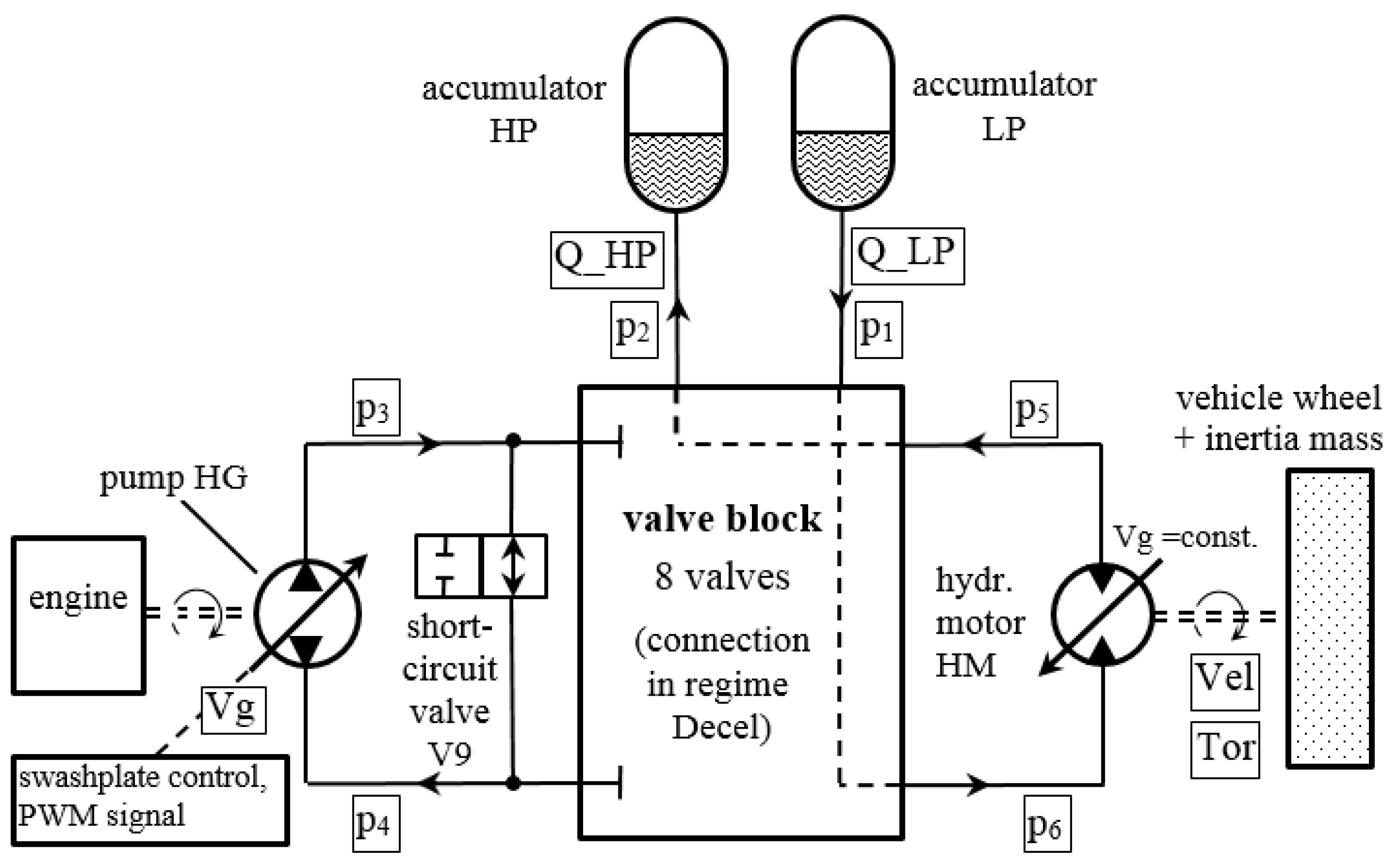
In this article, the identification and optimization of the working and structural parameters of the radial piston pump in the hydraulic circuit for energy recovery in mobile machines (
Figure 1) was carried out.
After formulating the mathematical model, the paper performed a mathematical interpretation of the phenomena that occur in the entire physical model, i.e., a simulation of the physical system was performed. When analyzing a concrete physical system, the boundaries of the system, the subsystems that make it up and their mutual connections, as well as the processes that take place in it, are defined. Then assumptions and mathematical models of all previously defined processes were determined. The resulting systems of equations and their interconnections represent a simulation of the physical model. After all, experimental verification of the obtained results was performed and their accuracy was analyzed.
The hydrodynamics of radial-piston pumps includes current and hydrodynamic processes in the pump cylinder, suction and discharge piping, suction and discharge chamber and pump distribution organs. Current processes in the pump cylinder during the high-pressure part of the cycle were analyzed due to the occurrence of pressure pulsation. Current processes in the suction and discharge pipeline, suction and discharge chamber and distribution organs (valves) were analyzed in order to determine the influence of the structure of the suction and discharge pipeline and the law of opening distribution organs (valves) for filling and emptying the pump cylinder.
2. Mathematical Modeling
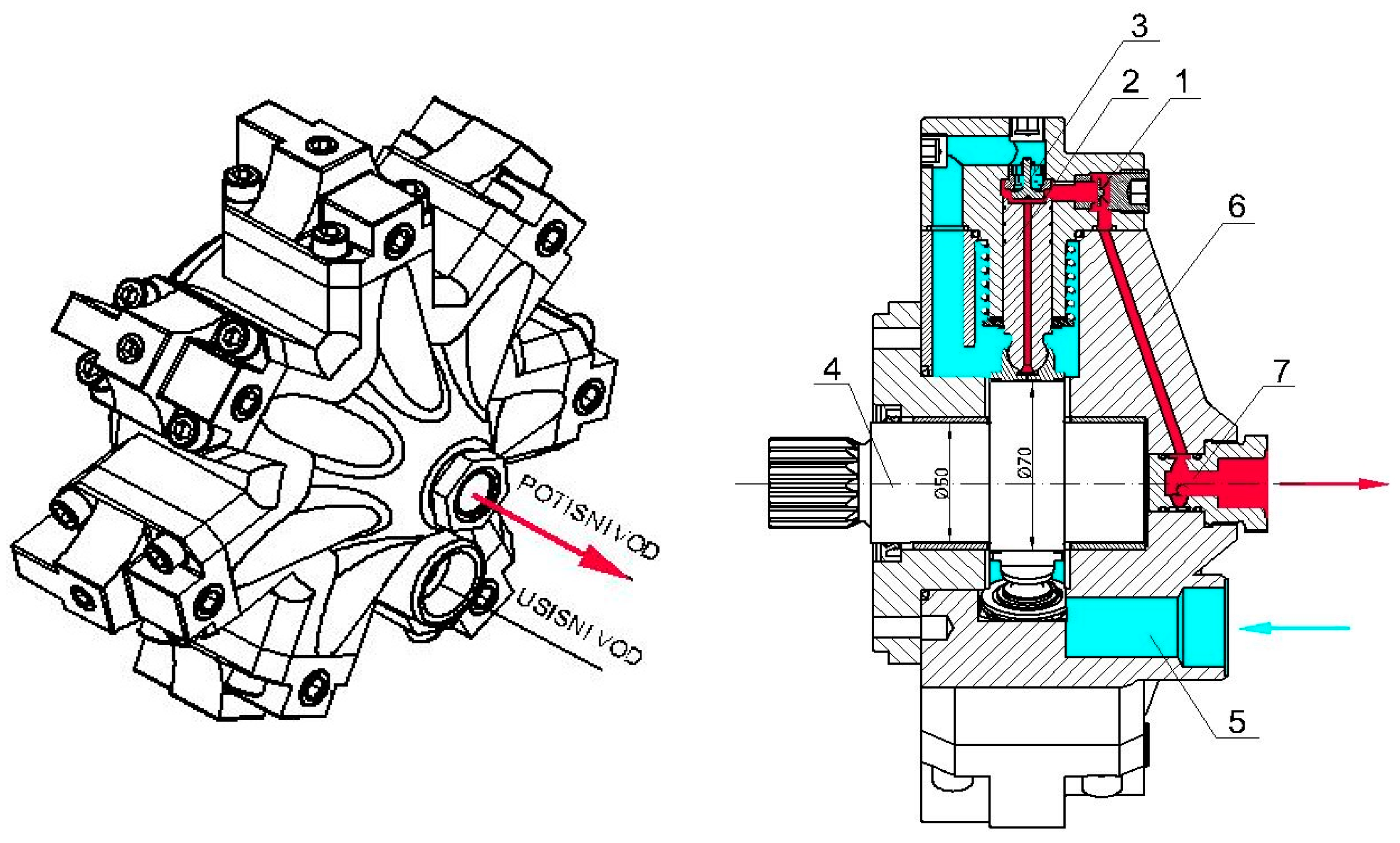
For mathematical modeling of hydrodynamic and dynamic processes in a radial-piston pump (pump cylinder, suction and discharge chamber, suction and discharge valve and high-pressure pipeline),
Figure 2, the following general assumptions are adopted:
a) Changes in the state of the fluid are quasi-stationary, except in the pressure pipeline;
b) The kinetic energy of the fluid in all control spaces except for the pressure pipeline is ignored;
c) Fluid discharge through gaps (gaps between piston and cylinder and pressure valve) is quasi-stationary;
d) Processes in control rooms are isothermal or isentropic;
e) Field forces (gravity, etc.) are neglected.
A mathematical model is provided for each element, considering the complexity of individual processes and their interdependence, as well as the need for further improvement of mathematical modeling. In this way, modular programming on the computer and further improvement and monitoring of the computer program are greatly facilitated.
2.1. Mathematical Modeling of Valves
The role and location of the suction and discharge valves can be seen in
Figure 2, where the pump is shown in isometry and in section. The first phase of the mathematical modeling of the valve refers to the determination of the sizes of the flow sections of the valve. For the valve separation of fluid in radial-piston pumps, the size of the geometric flow section depends on the stroke of the valve. parameters and then highlight the differences in terms of their functions
The size of the geometrical flow pressure of the valve is determined by the expression:
With the connection
dϕ = ωdt, the differential equation of movement of the moving mass of the valve is arrived at, to which 1/3 of the mass of the valve spring is added, in the form:
where F
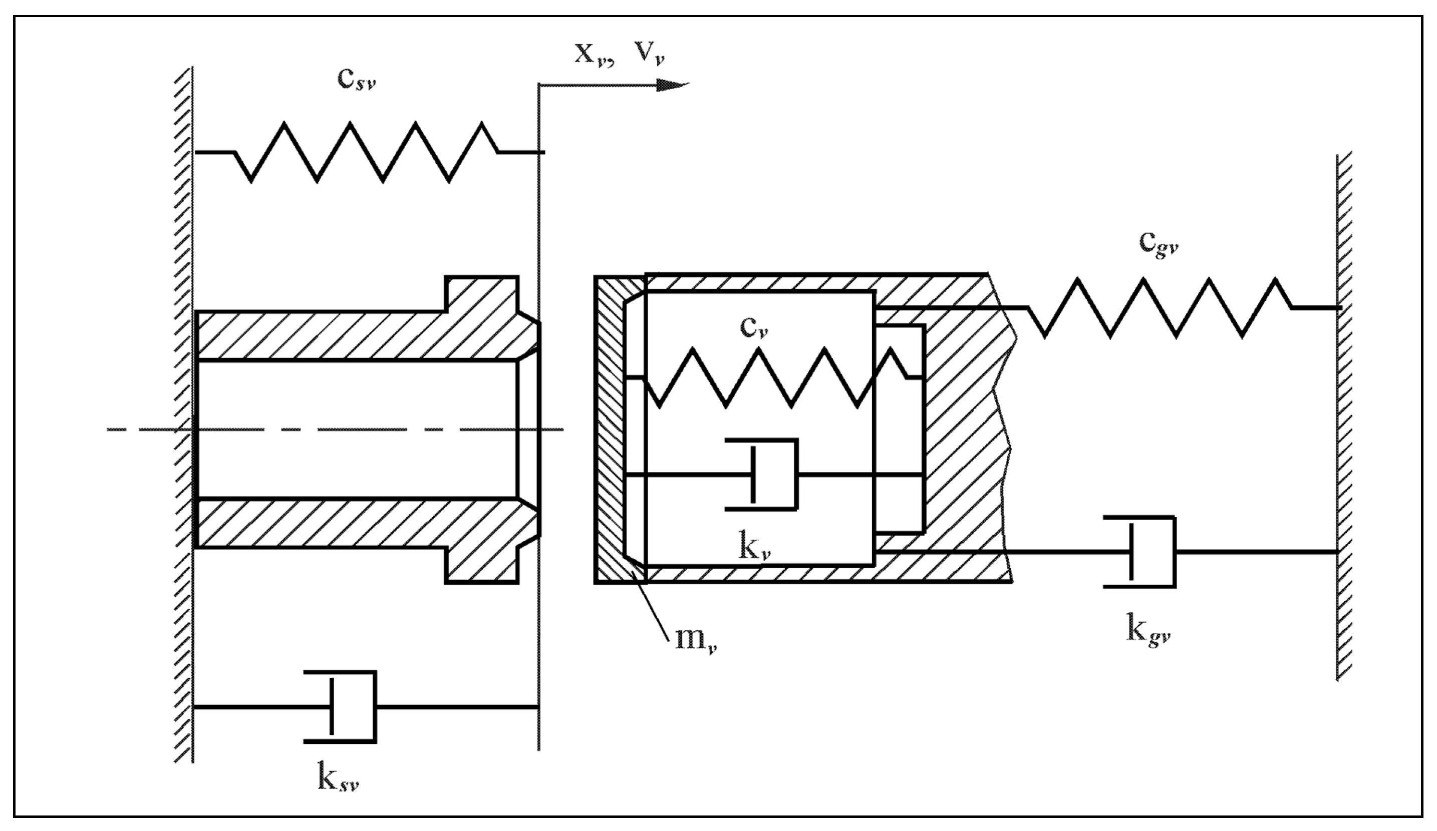
v is the resultant of all forces acting on the moving mass of the valve mv, which depend on the position of the moving mass. All elements are shown in
Figure 3.
During valve stroke 0 < x
v < h
v, the resultant of all forces acting on the valve consists of fluid pressure force, spring force, friction force proportional to the first degree of speed and constant friction force:
where are:
σ =1 for vv > 0
σ = -1 for vv < 0
hv - maximum valve stroke
When the stroke of the valve is x
v > h
v, the valve is additionally acted upon by a force originating from the deflection of the valve stop and the damping force that additionally occurs during the deformation of the stop (it is assumed that this force is proportional to the first degree of the deformation rate):
where are:
σgv =0 for xv ≤ hv
σgv =1 for xv > hv.
In the case when xv < 0, the valve is additionally acted upon by a force originating from the deformation of the valve seat and the damping force that additionally occurs during the deformation of the valve seat (proportional to the first degree of deformation rate):
where are:
σgv =0 for xv ≤ 0
σgv =1 for xv > 0.
The differential equation of the valve path is:
The effective flow section of the valve through which the fluid flows in or out is obtained as a product of the geometric flow section and the corresponding flow coefficient, i.e.,:
When it is a suction or discharge valve, all the expressions (1) to (7) given above receive the corresponding indices ( u - when it is a suction, that is, when it is a discharge valve).
This is the first phase of modeling and represents the basis for all other phases, both modeling and design of the valves of the suction and discharge lines of the radial-piston pump.
2.2. Mathematical Model of a Pump Process
2.2.1. Processes in the Suction Chamber of the Pump
The mass flow m through opening, at the point of entry of the suction pipe into the suction chamber of the pump, during quasi-stationary discharge is calculated from the known relation for stationary discharge of an incompressible fluid:
where are:
p - pressure,
ρ –fluid density,
А –geometric flow section,
μ - flow coefficient constant.
The index “1” refers to the opening, the index “u” to the suction, the index “s” to the suction chamber.
The magnitudes of the constant σ1 are
σ1 = 1 for pu ≥ ps
σ1 = –1 for pu < ps
In a similar way, the mass flow of the fluid
m through the distribution organ of the pump (distribution plate or valves) when filling one cylinder of the pump is calculated:
where are:
σu = 1 for ps ≥ pc ,
σu = –1 for ps < pc ,
Аu - geometrical flow section, intake opening of the distribution board or intake valve opening.
The index “c” refers to the cylinder.
The mass balance of the suction chamber reads:
where are:
ј = 1, 2, ..., zc serial number of the cylinder,
zc - total number of cylinders.
The density of the fluid in the suction chamber of the pump is:
Vs is the volume of the suction chamber
Logarithmic differentiation of this equation by time yields:
The equation of state of the fluid for pressure
p and temperature
T can be written in the form:
The total derivative of pressure with time during an isothermal change of state (T = const) can be written in the form:
For
m =ρ V the following differential can be written:
The isothermal coefficient of compressibility of the fluid
εr is defined by the equation:
Based on Equations (14), (15) and (16), the following relationship between pressure, density and isothermal compressibility coefficient is obtained:
In the case of isentropic change (s = const) the equation of state can be written in the form:
The total pressure time derivative in this case is:
The isentropic coefficient of fluid compressibility
εs is:
Based on Equations (15), (19) and (20), the relationship between pressure, density and isentropic compressibility coefficient is obtained:
Comparing Equations (17) and (21) shows a complete similarity, so a general equation for the relationship between pressure, density and compressibility coefficient can be written:
i.e., in the form:
where in are:
ε = εT – for isothermal change of state
ε = εs – for an isentropic change of state.
Using Equations (10), (12) and (23), the differential pressure equation in the suction chamber of the pump is obtained in the form:
where are:
j=1, 2,..., zc serial number of the cylinder,
zc – total number of cylinders.
Since the volume of the suction chamber is constant, and the elementary rotation angle
ϕ of the drive shaft can be expressed through the angular velocity
ω (
dϕ = ωdt), and that the relation between the compressibility coefficient and the modulus of elasticity is
ε = 1/E, the differential equation of the pressure in the suction chamber of the pump, expressed through the rotation angle of the drive shaft and the mass flow is:
2.2.2. Processes in the Pump Cylinder
The mass flow of the fluid flowing into the cylinder through the hole in the piston is defined by Equation (9), and the mass flow of the fluid flowing out of the cylinder is:
where are:
σI = 1 for pc ≥ pv ,
σI = -1 for pc < pv ,
Ai - geometric flow section of the pressure opening of the distribution board or pressure valve opening.The index “i” refers to outflow.
Applying the law of conservation of mass to the pump cylinder, it follows that the change in mass in the cylinder caused by the flow of fluid into the cylinder and the flow out of the cylinder will be:
The density of the fluid in the cylinder is
Logarithmic differentiation of this equation by time yields:
Using relation (23) and Equations (27) and (29), the differential pressure equation in the pump cylinder is obtained in the form:
The current volume of the cylinder is:
The change in the volume of the pump cylinder caused by the movement of the piston is:
where are:
xk - current stroke of the piston calculated from the outer dead center
By replacing the relation (32), introducing the connection
dϕ =
ωdt and the modulus of elasticity E, the differential Equation (30) expressed through the mass flow and the rotation angle of the drive shaft reads:
The change in volume of the pump cylinder caused by the movement of the piston is:
where are:
xk - current stroke of the piston calculated from the outer dead center
By replacing the relation (34), introducing the connection
dϕ =
ωdt and the modulus of elasticity E, the differential Equation (32) expressed through the mass flow and the rotation angle of the drive shaft reads:
2.2.3. Processes in the Pressure Chamber of the Pump
Applying the law of mass maintenance to the pressure chamber of the pump, it follows that the change in mass is caused by the flow of fluid from j cylinders through the distribution bodies (distribution plate or pressure valves) and flow through the pressure pipeline .
The mass balance of the pressure chamber reads:
where are:
j=1, 2,..., zc serial number of the cylinder,
zc – total number of cylinders.
The mass flow flowing out of the thrust chamber into the thrust pipeline is
where are:
σ2 = 1 for pv ≥ pn ,
σ2 = -1 for pv < pn ,
A2 -geometric flow section of the pressure pipeline
Analogous derivation of the differential pressure equation in the suction chamber, using Equations (35), (36), and Equation (23) with appropriate index notation, leads to the differential pressure equation in the pump discharge chamber:
The constant size of the pressure chamber Vv is defined by the construction of the pump.
2.2.4. Structure and Organization of a Computer Program
In the previous subsections, the models of the process in the piston-radial pump were presented. The simultaneous integration of nonlinear differential equations of boundary conditions and partial differential equations of flow in the pressure pipeline required the application of a computer and the creation of a suitable computer program.
The program that connects and simultaneously solves all the mentioned differential equations, equations of changes in characteristic flow sections and changes in the physical characteristics of the fluid, required an appropriate structure and organization. The program was written in the programming language Digital Visual Fortran 5.0 and was realized on the measurement and control system ADS 2000-CODEX. The principles of structural and modular programming were used.
More important programs are written as rounded modules that connect to each other or to the main program, or can be used independently.
The AKSIP software system was specially developed for mathematical modeling of current and hydrodynamic processes during the entire working cycle of piston pumps with combined separation of the working fluid.
The AKSIP program is modularly designed and consists of the main AKSIP program and its modules.
The AKSIP program module performs loading and printing of input data and determination of constants. For further processing calls the ECITER module.
In case of deterministic model selection, the desired model is specified when creating the input data file AKSIP.DAT. Stochastic model selection is of particular interest in the statistical analysis of the reliability of modeling results.
The program is structured layered in several levels.
The transmission of all important data is achieved through COMMON blocks, while the coherence of the unit system is respected. The main program is called AKSIP and represents the first level. During operation, the main program calls the ECITER subroutine of the second level and initiates the initial values of the relevant variables.
The start of the calculation is defined in the input file by specifying the starting angle of the calculation. The parameters in the input file define which model of pump it is, which, among other things, determines the way of calculating certain sizes.
In the AKSIP program, for now, the following possibilities and corresponding identifiers are foreseen when choosing a mathematical model:
a) Pressure variability in the suction chamber IS=?
S=0 - the pressure in the suction chamber is constant or IS=1 - the pressure in the suction chamber is variable.
b) Pressure variability in the pressure chamber IT=?
IT=0 - the pressure in the pressure chamber is constant or IT=1 - the pressure in the pressure chamber is variable.
c) Selection of suction distribution organ IU=?
IU=1 - the suction distribution board is activated or IU=11 - the suction valve is activated.
d) Selection of pressure distribution body II=?
II=1 - the pressure distribution board is activated or II=11 - the pressure valve is activated.
e) Selection of the method of determining the flow coefficient IMDMI=?
IMDMI=0 - flow coefficients are given tabularly as constants,
IMDMI=1 - the flow coefficient is specified as a function of pressure,
IMDMI=2 - the flow coefficient is specified as a function of the number of revolutions.
IMDMI=3 - the flow coefficient is specified as a function of pressure and speed.
f) Selection of a model that takes into account the mass inertia of the working fluid IMIN=?
IMIN=0 - the inertia of the mass of the working fluid is not taken into account, IMIN=1 - the inertia of the mass of the working fluid is taken into account.
The second level of the program consists of a module for integration of nonlinear ordinary differential equations of Euler-Cauchy boundary conditions with iterations (ECITER). Depending on the pump model, this module calls a specific subroutine of the third level (FUNC) with boundary condition equations, through which a connection is established with other subroutines of the fourth level, which include: subroutine for finding flow parameters at pipe ends (UCEVG), subroutine for finding parameters flow inside the pipe (UCEV), subprogram for finding the kinematic characteristics of the piston (KINS), subprogram for finding the current effective inlet and outlet flow sections of the distribution board (KPLU, KPLI), subprogram for calculating the current effective flow sections of the intake and discharge valves (KAVEU, KAVEI ) and a module for determining the physical characteristics of fluids (GORKO, GORKOS).
3. Experimental Testing
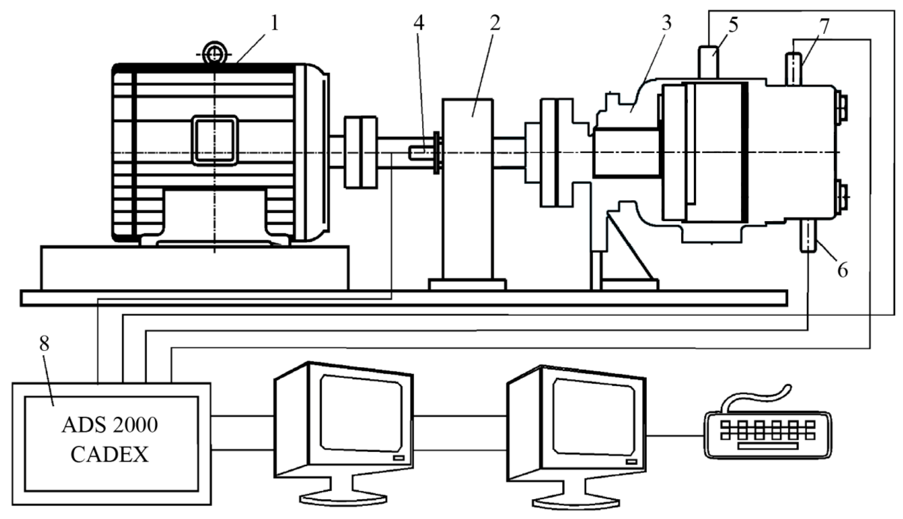
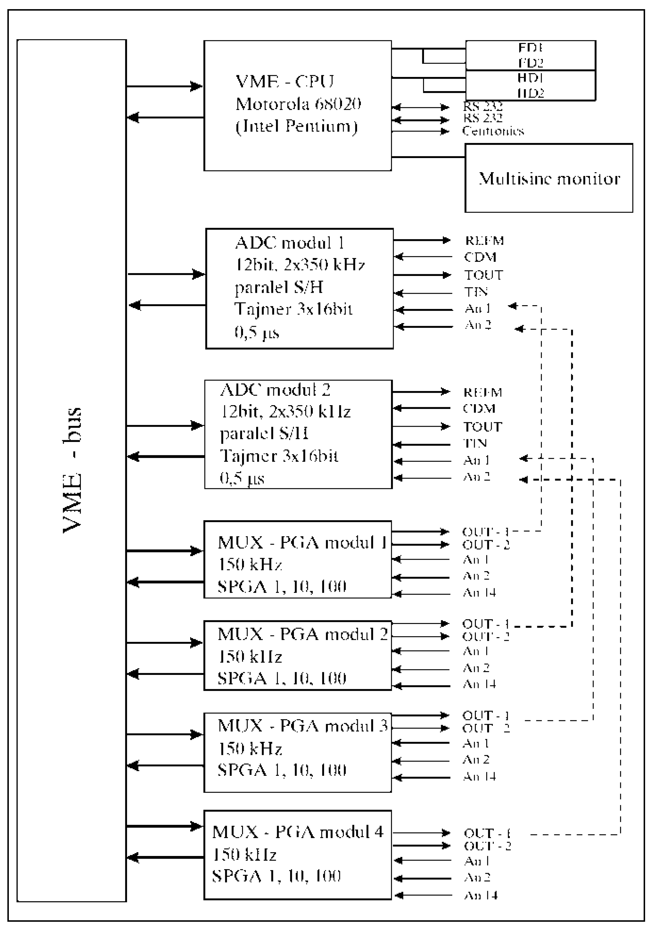
Model of the pump was prepared in such a way as to enable the connection of the necessary measuring transducers necessary for the measurement of characteristic parameters. A schematic view of the test installation and data acquisition system is shown in
Figure 4
The following sizes were measured:
Pressure pc in the cylinder as a function of the pump drive shaft angle
Pressure pv pv in the valve chamber as a function of the pump drive shaft angle
Pressure pn in the pressure pipeline as a function of the angle of the pump drive shaft
Amplitude of vibration of the pump casing as a function of the angle of the pump drive shaft.
Angleϕ of the pump drive shaft
Pump flow Qp
Temperature of the working fluid T
Number of revolutions n of the drive shaft of the pump.
Structure of the ADS 2000-CADEX measurement and acquisition system. It is given in
Figure 5. VME-bus ADC contains 2 A/D converters with simultaneous operation of the speed 2 times 350 kHz at 12 bit, 1 timer, the start of each conversion is performed via the pulse of the angle encoder or the timer, with hardware registration of the reference brand of the incremental angle encoder in order to 100 % control of the correctness of the operation of the angle encoder in real time. Up to 6 A/D cards = 12 A/D converters can be integrated into the system. Two VME-bus ADC modules are installed in the implemented system.
The VME-bus PGA multiplexer and amplifier module has six high-speed instrument amplifiers for direct connection of tape measure transmitters connected in a full bridge with a DC-supply of 5 V (opc. 12 or 15). Maximum switching speed 150 kHz. 4 VME-bus PGA modules are integrated into the implemented system.
The system has an interface for incremental angle encoders with DC-supply and multiplication of angle encoder pulses, i.e., with interpolation of angle marks with the desired factor 1, 2, 3 ... 9. to 4 interfaces for angle encoders can be integrated into the system.
The applied measurement system enables simultaneous measurement on 4 fast analog channels each, with parallel measurement of time intervals from the angle mark to the mark of the incremental angle encoder.
4. Results of Mathematical Modeling and Experimental Testing
As part of the experimental tests, the pressure flow in the cylinder, the pressure space and the pressure pipeline were measured, as well as the vibration of the pump housing depending on the angle of the drive shaft. All pressures and vibrations were measured completely parallel every approx. 0,09° of the pump drive shaft (exactly 4096 times per one revolution of the shaft). An optical encoder with 1024 pulses per revolution was used as an incremental angle encoder. The angle encoder pulses are quadrupled using the angle encoder interface on the ADS 2000 system, so that 4096 pulses are obtained per shaft revolution.
In order to see the reproducibility of consecutive cycles at unchanged operating mode, 10 consecutive cycles were measured. At the same time, the time interval from corner to corner was measured in order to determine the uniformity of the angular speed of the drive shaft and to control the operation of the incremental angle encoder. All analog signals (pressure, vibration) are converted into digital form in parallel using four (4) ultra-fast converters that work simultaneously (parallel). The total number of measured data was (4+1)x4096 = 20480 per revolution (cycle), i.e., 204800 for 10 consecutive cycles. The number of samples of 4096 was not chosen randomly, but deliberately in order to apply the fast Fourier transform (FFT) of the measured signals. Measurements were made for seven operating modes.
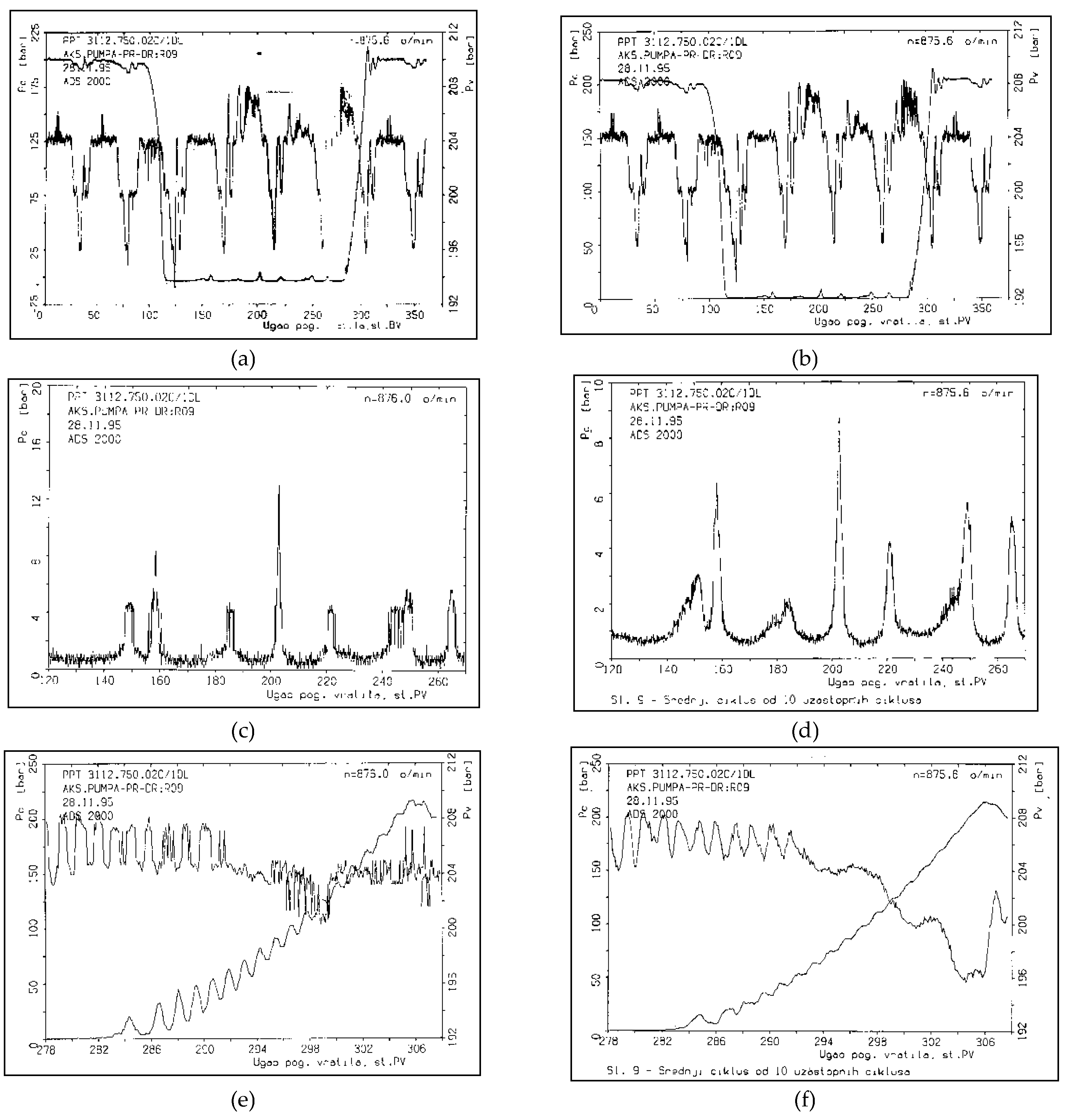
At the pump operating mode n=875.6 min-1 and pn=200 bar, the results of the measured pressures and the pressures obtained by mathematical modeling as a function of the rotation angle of the pump drive shaft are given in comparison.
The diagram shows the pressure gradients in the compression and expansion phase, as well as the appearance of pulsations during suction. Pressure pulsations in the pressure chamber depend on the number of cylinders, which is obvious in this mode of operation, because it is a pump with eight cylinders.
The appearance of pulsations in the suction phase at the angular interval of the drive shaft from 120 - 270
O is shown in
Figure 6c and
Figure 6d.
Figure 6e and 6f show the measured flow of pressure in the cylinder (p
c) at the angular interval of the drive shaft from 278-307°, with the aim of analyzing in more detail the pressure increase gradient in the compression phase. Pressure pulsations in the pressure chamber are also shown on the same diagrams in the same interval.
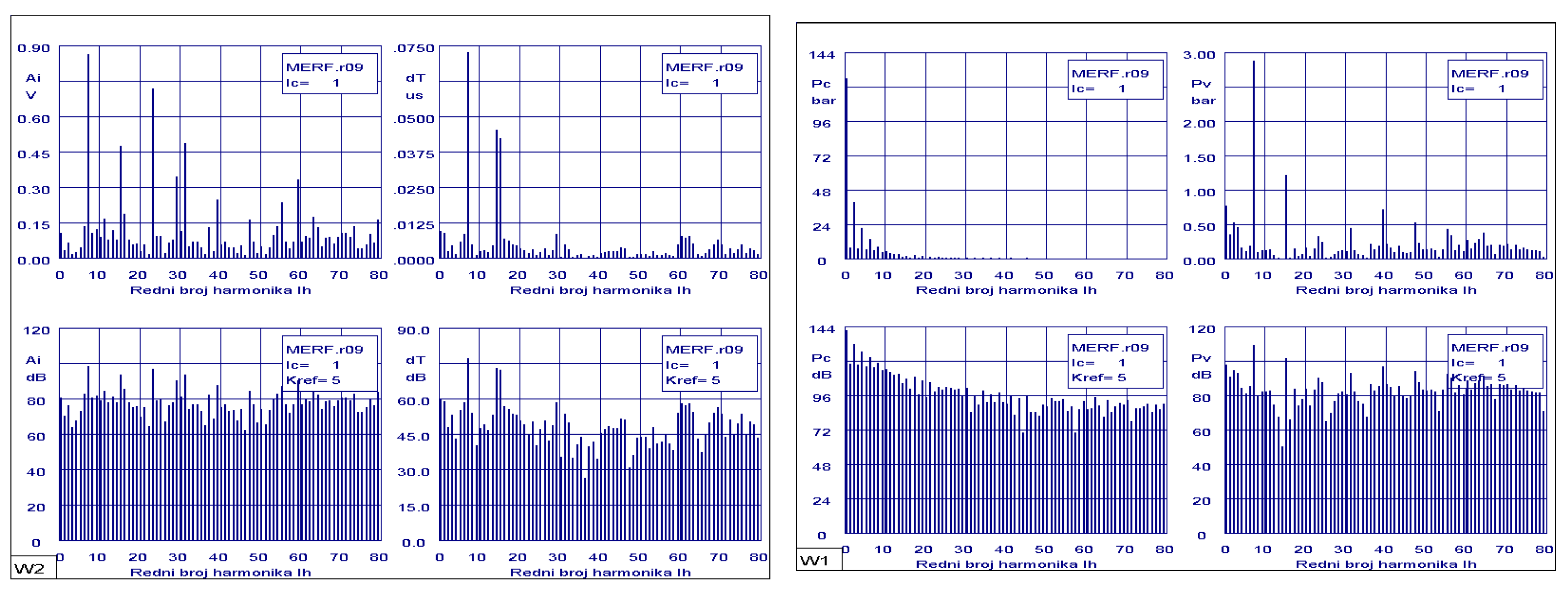
The magnitudes of the measured vibration amplitudes of the pump housing for the middle of ten consecutive cycles shown in
Figure 7. The applied decibel scale enables an easier comparison of the absolute level of the amplitudes of the measured quantities according to the recommended reference level.
The vibration level is defined by the amplitude ratio as follows
where are:
N - number of decibels
A - measured level
Aref =10Kref - reference level
The reference level is marked with the Kref exponent on the corresponding diagrams.
From the attached diagrams of the harmonic analysis of the pressures in the pressure chamber, a dominant row for the maximum pressure amplitudes can be seen, which contains a module equal to the number of cylinders , where z is the number of cylinders and n= 1,2,3.. number of cycles.).
The magnitudes of the measured vibrations of the pump casing for the middle of ten consecutive cycles shown in
Figure 7 also indicate the occurrence of amplitude pulsations at harmonics
.
These statements are in principle valid for all tested modes of operation of the piston-radial pump.
5. Conclusions
By measuring the performance of piston-radial pumps, it was concluded that their efficiency can generally be evaluated according to their maximum working pressure capacity and flow rate at a certain drive speed.
The parameters of the hydrodynamic process of the piston-radial pump (pressure flow, suction flow and compression flow) cannot be determined accurately enough purely experimentally, and also not purely mathematically. Sufficiently accurate parameters can be obtained by the combined application of pressure flow measurement in the cylinder, mathematical modeling of the actual hydrodynamic process and nonlinear optimization methods, whereby systematic measurement errors and unknown parameters can be simultaneously determined.
The pump never delivers this theoretical or calculated flow rate. How close you are to reaching this number is called volumetric efficiency. It is calculated by comparing the theoretical flow rate with the practical or actual flow rate and varies with speed, pressure and pump design.
Mechanical efficiency is also less than perfect, as there are energy losses due to friction at the inlet. The overall efficiency of a hydraulic pump is obtained by multiplying its volumetric and mechanical efficiency.
Due to their construction, these pumps offer two qualities that others do not: on the one hand, a positive seal between inlet and outlet, allowing higher pressures without excessive internal leakage. On the other hand, in many pumps of this type, the lubrication of moving parts other than pistons and cylinders can be independent of the fluid being pumped, which allows fluids with poor lubrication properties to be used. Volumetric and overall efficiencies are close to those of axial pumps.
The piston-radial pump is an important component in hydraulic systems in mobile applications, from construction and agricultural equipment to heavy trucks because of the power density for a range of work functions. Optimizing the operating and structural parameters of piston-radial pumps can directly influence the efficiency of mobile machines.
Further directions of research are possible in the construction of piston pumps in the areas of: separation of the working fluid, dynamics of the cylinder block and hydrodynamic processes in the gaps between the piston and the cylinder in the cylinder block.
References
- Vacca,A., Franzoni, G.,Hydraulic Fluid Power: Fundamentals, Applications, and Circuit Design,Wiley,2021.
- Akers, A., Gassman, M., Smith, R., Hydraulic Power System Analysis (1st ed.), CRC Press, 2006. [CrossRef]
- Manrig, N., Fluid Power Pumps and Motors: Analysis, Design and Control (1st ed), McGraw Hill,2013.
- Matthies, H.,J., Renius, K.,T., Einführung in die Ölhydraulik, GWV Fachverlage GmbH, Wiesbaden, 2008.
- Yang, H., Pan, M.,Engineering research in fluid power: a review, J. Zhejiang Univ. Sci., 16, pp. 427–442, 2015. [CrossRef]
- Petrović, R.,Mathematical Modeling and Experimental Research of Characteristic Parameters Hydrodynamic Processes of a Piston Axial Pump,Strojniški vestnik - Journal of Mechanical Engineering, 55, pp. 222-229,2009.
- Bech,T.,Olsen,S.,Klit,P., Design ofPumpsfor WaterHydraulicSystems, 6thScandinavian International Conference on Fluid Power, SICFP’99, Tampere, Finland,1999.
- Jourani, A., Hagege, B., Bouvier, S., Bigerelle, M., Zahouani, H., Influence of abrasive grain geometry on friction coefficient and wear rate in belt finishing. Tribology International, 59, pp. 30-37, 2013. [CrossRef]
- Yang,H.,Yang,J.,Zhou,H.,Research on materials of piston and cylinder of waterhydraulic pump, Industrial Lubrication and Tribology, Volume 55, Number 1, pp. 38-43,2003.
- Songlin, N., Ming, G., Fanglong, Y., Hui, J., Zhonghai, M., Zhen, H., Xin, Z.,Research on fluid-structure interaction for piston/cylinder tribopair of seawater hydraulic axial piston pump in deep-sea environment,Ocean Engineering, 219, pp. 108222, 2019. [CrossRef]
- Qun, C., Junhui, Z., Bing, X., Qiannan, W., Hsinpu, H.,Test rigs and experimental studies of the slipper bearing in axial piston pumps, Measurement, 132, pp. 135-149, 2019. [CrossRef]
- Vacca, А., Klop, R., Ivantysynova, M., A numerical approach for the evaluation of the effects of air release and vapour cavitation on effective flow rate of axial piston machines,International Journal of Fluid Power, 11, No. 1 pp. 33-45, 2010. [CrossRef]
- Zhou, J., Zhou, J., Jing, C.,Experimental research on the dynamic lubricating performance of slipper/swash plate interface in axial piston pumps, Chin. J. Mech. Eng. 33, 25, 2020.10.1186/s10033-020-00441-7.
- Spencer, N.,A.,Design and development of a novel test method to measurethe slipper/swashplate interface fluid film in a positive displacement machine, Purdue University, 2014.
- Ham, Y., B., Lee, Y., B., Park, K., M., Choi, B., O., A study on the application of birfield joint to a water hydraulic piston pump for low leakage and low friction pumping, Proceedings of the 6th JFPS International Symposium on Fluid Power, Tsukuba, 2005.
- Canbulut, F., Sinanoğlu, C., Koc, E., Experimental analysis of frictional power loss of hydrostatic slipper bearings, Industrial Lubrication and Tribology , vol.61, pp.123-131, 2009. [CrossRef]
- Załuski, P. (2021). Experimental Research of an Axial Piston Pump with Displaced Swash Plate Axis of Rotation, Advances in Hydraulic and Pneumatic Drives and Control NSHP 2020, pp. 135–145, 2020. [CrossRef]
- Manring, N., D., Wray, C.,L., Dong, Z.,L.,Experimental studies on the performance ofslipper bearings within axial-piston pumps,Journal Tribol.,126 (3), pp. 511-518, 2004.
|
Disclaimer/Publisher’s Note: The statements, opinions and data contained in all publications are solely those of the individual author(s) and contributor(s) and not of MDPI and/or the editor(s). MDPI and/or the editor(s) disclaim responsibility for any injury to people or property resulting from any ideas, methods, instructions or products referred to in the content. |
© 2024 by the authors. Licensee MDPI, Basel, Switzerland. This article is an open access article distributed under the terms and conditions of the Creative Commons Attribution (CC BY) license (http://creativecommons.org/licenses/by/4.0/).
