Submitted:
02 November 2024
Posted:
06 November 2024
You are already at the latest version
Abstract
Pile foundations are widely employed in engineering to bolster structures and efficiently transmit loads to the underlying soil or rock. However, in karst terrains, the occurrence of multi-layered stone projections or caves can drastically affect the bearing capacity and stability of these pile foundations. In order to study the influencing factors of vertical bearing capacity of pile founda-tion in multi-layer karst cave environment, the bearing capacity test of pile foundation was carried out at the construction site. The results show that with the increase of external load eccentricity, the bearing capacity of pile foundation decreases obviously. Subsequently, we developed a finite element model for pile foundations in a double-layered karst area using the commercial general finite element software ANSYS. This model facilitated our analysis of the bearing capacity of concrete pile foundations under progressively increasing loads, accounting for variations in rock height, eccentricity, and elastic modulus. The findings reveal the following: (1) Under consistent external loading, the maximum displacement of pile foundations increases with eccentricity. (2) As concrete strength rises, the maximum displacement gradually decreases, while the corresponding peak stress remains approximately constant. (3) The height of karst caves significantly impacts the bearing capacity of pile foundations. Therefore, during construction, it is crucial to minimize or avoid traversing areas with high karst caves. In engineering applications involving multi-layered karst landforms, it is essential to assess the bearing capacity of pile foundations beforehand, paying particular attention to the effects of karst cave height, pile eccentricity, and concrete strength on the bearing capacity. This will enable the optimization of the design scheme, avoidance of high karst cave areas, and ensure the safety and stability of the structure.
Keywords:
multi-layer karst area
; experimental research
; numerical simulation
; vertical bearing capacity
; pile foundation
; eccentricity
1. Introduction
China stands as one of the global leaders in terms of the extensive distribution, vast coverage, and diverse types of karst landscapes. Reinforced concrete pile foundations possess the following advantages: convenient production, high pile body strength, excellent corrosion resistance, ability to bear large loads, unaffected by groundwater or damp environments, high degree of mechanization in construction, and adaptability to different soil layers for construction, which enhances ground bearing capacity and ensures the stability of buildings. Therefore, they have been widely applied in foundation treatment projects in karst regions. With the implementation of China 's Western Development strategy, a large amount of high-grade highway construction will pass through western mountainous areas, and a large number of engineering pile foundations will pass through karst development areas. The complex and changeable karst areas have brought great difficulties to the construction of highway bridge pile foundations. Therefore, it is of great practical and engineering significance to study the bearing characteristics of bridge pile foundation in karst area, especially the pile foundation passing through multi-layer karst.
Many scholars have systematically studied the vertical bearing characteristics of pile foundations in karst development areas. Wang et al. calculated the influence of the height and length of pile side holes on the vertical bearing capacity of pile foundations via numerical analysis. Chen et al. studied the bearing characteristics and load transfer mechanisms of pile foundations crossing karst caves with different scales and layers via a centrifugal model test, and attributed the sensitivity of the vertical bearing capacity of pile foundations to three factors. Liu et al. established a regression model of the load settlement relationship of pile foundations by using field static load test data. Compared with the numerical simulation results, they showed that the model can effectively predict the settlement of pile foundations. Su et al. studied the influence of cave radius, cave vertical spacing and cave height on the vertical bearing characteristics of pile foundations under the conditions of double-layer caves via a numerical simulation method. The results show that cave span affects the side friction of the whole upper, middle, and lower sections of pile foundations, and the vertical spacing of a cave has a great influence on the side friction of the middle section of a pile foundation. Ai et al. used the finite element method to simulate the influence of rock thickness on the stress characteristics of bridge pile foundations in karst areas. From the simulation results, it can be seen that when rock thickness is thin, the upper load is borne by the pile end resistance. When the thickness of a rock layer is thick, the pile end resistance and the pile side friction bear the load together. Feng et al. used a theoretical model to predict the bearing capacity of pile foundations under the influence of underlying karst caves. The results show that the theoretical model can predict the bearing capacity of pile foundations well. Jiang et al. analyzed the calculation method of the bearing capacity of pile foundations under the action of underlying karst caves, and put forward a new calculation method of roof thickness. Huang et al. used the numerical modeling of pile foundations in karst areas of the Chongqing_Guizhou railway to analyze the vertical bearing characteristics of pile foundations crossing multi-layer karst caves, and put forward two different shear failure modes of karst cave roofs. The thicknesses of rock strata and the span ratios of karst caves are different, and the failure modes of rock strata are different. The lateral friction resistances of pile foundations in karst caves are greatly attenuated. On the basis of the measured data, HORVATH et al. established a relationship between the pile side resistance and the saturated uniaxial compressive strength of rock. Carrubba et al. carried out field tests to obtain the relationship between the pile side resistance and the uniaxial compressive strength of bedrock. Based on the modified Hoek_Brown strength criterion, Serrano et al. [11,12] proposed a calculation method for the ultimate bearing capacity of rock-socketed piles in soft and hard rocks, and analyzed its bearing mechanism. Khan et al. used a finite element model to simulate the pile_rock interface, and analyzed the influence of the roughness of the pile_rock interface on the bearing capacity of pile foundations. Singh et al. studied the bearing characteristics of rock-socketed piles under an inclined load via numerical simulation, and analyzed the influence of rock-socketed depth and other factors on the bearing capacity of pile foundations. To sum up, although a large number of scholars have studied the influence of karst caves on bridge pile foundations, most of them consider the influence of a single karst cave [15,16].In practical engineering, pile foundations need to cross multi-layer karst caves, and the design and calculation method of the bearing capacity of pile foundations crossing multi-layer karst caves is not given in the current code [17,18,19].Although many scholars have conducted some studies on the vertical bearing characteristics of pile foundations in karst areas, the research on pile foundation under double-layer karst geology and multi-layer karst geology is not enough. In particular, the effects of external load, rock height, oblique load and pile material on the vertical bearing characteristics of pile foundation under double-layer karst geology and multi-layer karst geology are still unclear, so further research is needed.
In order to study the influence factors of the vertical bearing capacity of pile foundations under the special condition of multi-layer karst caves, we first tested the bearing capacity of pile foundation at the construction site and a finite element model of double-layer karst pile foundations was established by using ANSYS Workbench commercial general finite element software. This model was employed to analyze the bearing capacity of concrete pile foundations with varying rock heights, eccentricities, and elastic moduli, under progressively increasing loads. This study analyzes the bearing characteristics of multi-layer karst pile foundation by finite element model, guides the design and construction of multi-layer karst pile foundation, and optimizes parameters to cope with complex geological conditions.
2. Engineering Geological Survey and Working Condition Setting
2.1. Engineering Geological Survey
The project is located on the east side of the intersection of the entrance and exit of the Dunan Expressway in Mashan County, Nanning City, Guangxi Province, and the provincial highway 20324 line. The site landform is a karst basin. The geological conditions are shown in Figure 1. The numbers on the left in Figure 1 represent the height of the sections themselves, and the numbers on the right represent the height of the bottom of the sections from the ground. The first layer is back-fill soil with a height of 3.8 m. The second layer is broken limestone with a height of 0.6 m. The third layer is a karst cave with a height of 4.5 m. The fourth layer is broken limestone with a height of 2.4 m. The fifth layer is a karst cave with a height of 3.2 m. The sixth layer is relatively complete limestone. The height of the pile is 15 m, and the most complete limestone is 0.5 m.
Pile foundations in karst geology are easily affected by various factors. This paper will mainly analyze the influence of different eccentricities, different diameters and different elastic moduli on the bearing capacity of pile foundations. According to Section 5.3.5 in the “ Technical code for building pile foundation “( JGJ94-2008) [18]:
where is the standard value of the ultimate lateral resistance of the first layer of soil on the pile side, and is the standard value of the ultimate end resistance.
The standard value,, of the vertical ultimate bearing capacity of a single pile with a pile diameter of 1.0 m is estimated. When a ZK05 drilling hole is selected, when the pile end enters the broken limestone layer of 2.00 m, the standard value,, of the vertical ultimate bearing capacity of a single pile can reach 8842.87 KN ( the pile length is about 22.72 m). When a ZK19 borehole is selected, when the pile end enters the more complete limestone layer of 1.00 m, the standard value of the vertical ultimate bearing capacity of a single pile,, can reach 9132.47 KN (the pile length is about 16.10 m), of which the more broken limestone layer,, is 21.6 MPa, and the more complete limestone layer,, is 51.9 MPa.
In order to ensure the safety and stability of the test, the static load test of the implanted pile adopts the slow maintenance static load method, and the pressure platform is used as the reaction device. In the test, the load is applied in stages, and the load of each stage is 1/10 of the estimated maximum test load, so as to realize the step-by-step evaluation of the bearing capacity of the reinforcement. After each load is applied, the settlement of the pile top is continuously monitored until the two consecutive readings are less than 0.1mm within one hour, which is considered as a stable state. The unloading process follows the principle of gradual equivalence, and the unloading amount of each stage is twice that of the graded load at the time of loading.
In the static load test of the vertical reinforcement of the foundation pile, the maximum load value of the test is 3600 KN, which is close to the maximum strength of the pile body. The selected four test piles of 1#, 2#, 3# and 4# all show good bearing performance, which is in line with the bearing capacity characteristics of the pile foundation in continuous and complete soil layer. Among them, 1#, 2#, 3# and 4# represent the eccentricity of the external load of 0,0.002,0.01 and 0.015, respectively. As shown in Figure 2 (a), the Q-S curve shows a slow-varying characteristic, and no obvious starting point of steep drop is observed. In the unloading stage, the rebound of the pile top under the last load is significant, which is 5.62 mm, 4.06 mm, 3.73 mm and 4.09 mm, respectively, which shows the large elastic deformation ability of the reinforcement during the loading process. After analysis, the ultimate bearing capacity of the reinforced body was determined to be 3600 kN, which did not reach its failure state, indicating that the pile has a high safety reserve. Figure 2 (b) shows the variation trend of the maximum settlement of pile foundation with the eccentricity of external load. It can be seen from the diagram that when the eccentricity of the external load is 0,0.002,0.01 and 0.015, the maximum settlement values of the pile foundation are 7.05 mm, 7.44 mm, 8.53 mm and 9.30 mm, respectively. Correspondingly, compared with the vertical loading, when the eccentricity of the external load becomes 0.002,0.01 and 0.015, the maximum settlement of the pile foundation increases by 5.5 %, 20.9 % and 31.9 %, respectively. It can be found that as the eccentricity of the external load increases, the maximum displacement of the pile foundation increases significantly. In order to further explore the influence of external load eccentricity on the bearing capacity of pile foundation. When the settlement of the pile foundation is 6mm, the corresponding external load is analyzed. As shown in Figure 2 (c), when the settlement of the pile foundation is 4.5mm, the external loads corresponding to the 1#, 2#, 3# and 4# pile foundations are 2880kN, 2696kN, 1980kN and 1780kN, respectively. In other words, when the eccentricity of the external load is 0.002,0.01 and 0.015, the bearing capacity of the pile foundation is reduced by 6.39%, 31.25 % and 38.19 % respectively under the same settlement.
3. Working Condition Setting
In this paper, the design bearing capacity of the AB type pile with an outer diameter of 500 mm and a wall thickness of 125 mm is 3701 KN. Therefore, three different working conditions are established for these three factors:
Condition 1: The AB (a kind of prestressed concrete hollow pipe pile) type punched cast-in-place pile with an outer diameter of 500 mm and a wall thickness of 125 mm is used to design the loading steps. The initial loading value is 2000 KN, the loading step is 500 KN, and the ultimate loading value is 5000 KN. The maximum displacement of the pile and the change in the maximum stress are studied under different eccentricity conditions. (2) The stress and strain of the same eccentricity and the same force are loaded. (3) Under the same force, the stress and strain change under different eccentricity conditions.
Condition 2: Using a 500 mm AB type punching pile, under the loading condition of working condition 1, the Young's modulus of the pile foundation material is changed, and the displacement and stress changes in concrete with different strengths under eccentricities of 0.005 and 0.01 are studied.
Condition 3: Change the height of the fourth layer of broken limestone and use the AB type punched cast-in-place pile with an outer diameter of 500 mm. The design value of the vertical bearing capacity of the pile body is 3701 KN, and the influence of the height of the karst cave on the bearing capacity of the pile foundation is studied.
4. Numerical Simulation
4.1. Finite Element Model
ANSYS has many advantages in simulating the bearing capacity of pile foundation in multi-layer karst cave. These advantages make ANSYS preferred software in the engineering community when simulating complex geological conditions and pile foundation structures. Due to the special conditions of karst geology and most of the broken limestone around pile foundations, the stress mode of the pile used in this model is mainly the end force. The pile established by the finite element method has a 50 mm interval with the surrounding soil. The contact relationship between the pile body and the surrounding limestone and soil layers and the contact relationship between the pile bottom and the limestone in contact with it are set to frictional. The friction coefficient is set to 0 [7,8]. The pile body is set as the active contact surface, and the surrounding limestone and soil are set as the passive contact surfaces. The contact between the first layer of backfill soil and the second layer of broken limestone is set to bonded. Fixed constraints are set on the surfaces of soil and limestone and the bottom of the lowest limestone. Because the stiffness of the pile is much larger than that of the surrounding rock and soil, the pile material is set to be linear elastic material, and the surrounding soil is set to be ideal elastic-plastic model, and the Drucker-Proger model is used to reflect its elastic-plastic characteristics. Due to the small influence on the soil outside a certain range, the soil with a diameter of 10 times the pile body and 2.5m deep soil under the pile body are taken to establish the finite element model. The finite element model is shown in Figure 3, and the required material parameters are shown in Table 1.
4.2. Numerical Simulation Results Analysis
According to the above three specific conditions, three different numerical simulations of parameter analysis are established. The influence of these three factors on the displacement and stress of pile foundations is reflected by changing the eccentric distance, Young's modulus, and pile diameter. This paper mainly discusses several kinds of eccentricity in the following Table 2.
4.2.1. Effect of Eccentricity on Pile Deformation and Bearing Capacity
In order to verify the accuracy of ANSYS finite element calculation results, the results obtained by experimental test and numerical simulation of pile foundation ae compared. Figure 4 shows the settlement results of experimental test and numerical simulation. It can be seen from the figure that the calculation results of experimental test and numerical simulation are basically consistent, thus verifying the accuracy of the finite element model used in this paper.
Figure 5 and Figure 6 show the maximum displacement and the displacement contour of pile foundations under different eccentricities and different loadings, respectively. It can be seen from the figure that, when the eccentricity is determined, the maximum displacement of pile foundations increases with an increase in loading. Taking an eccentricity of 0.001 as an example, when the external load is divided into 2000KN, 2500KN, 3000KN, 3500KN, 4000KN, 4500KN and 5000KN, the maximum displacement of the pile foundation is 4.30mm, 5.29mm, 6.27mm, 7.26mm, 8.24mm, 9.21mm and 10.17mm, respectively. Taking the eccentricity of 0.02 as an example, when the external load is divided into 2000KN, 2500KN, 3000KN, 3500KN, 4000KN, 4500KN and 5000KN, the maximum displacement of the pile foundation is 5.94mm, 7.32mm, 8.70mm, 10.07mm, 11.42mm, 12.76mm and 14.10mm, respectively. From the above data, it can be seen that the increase in the rate of the maximum displacement of the pile foundation increases with an increase in the eccentricity. The above variation law is consistent with the variation law of the field measured data in Section 2. When the external load is determined, the maximum displacement of the pile foundation increases with an increase in the eccentricity. Taking an external load of 2000 KN as an example, when the eccentricity is 0.001,0.002,0.005,0.01,0.015 and 0.02, the maximum displacement of the pile foundation is 4.30 mm, 4.33 mm, 4.41 mm, 4.99 mm, 5.45 mm, and 5.94 mm, respectively. Taking an external load of 5000 KN as an example, when the eccentricity is 0.001,0.002,0.005,0.01,0.015, and 0.02, the maximum displacement of the pile foundation is 10.17 mm, 10.24 mm, 10.47mm, 11.77mm, 12.91mm and 14.10mm, respectively. When the eccentricity is determined, the maximum displacement of the pile foundation increases with the increase in the external load. The reason for the above phenomenon is that when the eccentricity increases, the bending moment generated by the load on the pile foundation will also increase. The bending moment is the couple moment that causes the structure to bend and deform, which will cause the pile foundation to bend and deform more significantly under the action of load. Secondly, pile foundation usually consists of the pile body and the pile end, which jointly bear the load of the superstructure. When the eccentricity increases, the bending moment of pile body increases, and the bending deformation of pile body increases accordingly. This bending deformation causes greater deflection of the pile body, i.e., the displacement of the top of the pile relative to the bottom of the pile increases.
Figure 7 and Figure 8 show the maximum stress and the stress contour of pile foundations under different eccentricities and different loadings, respectively. It can be seen from the figure that, when the eccentricity is determined, the maximum stress of pile foundations increases with an increase in the loading. Taking an eccentricity of 0.001 as an example, when the external load is divided into 2000KN, 2500KN, 3000KN, 3500KN, 4000KN, 4500KN and 5000KN, the maximum displacement of pile foundation is 15.10 MPa, 18.84 MPa, 22.59 MPa, 26.34 MPa, 30.09 MPa, 33.84 MPa and 37.60 MPa. Taking an eccentricity of 0.02 as an example, when the external load is divided into 2000KN, 2500KN, 3000KN, 3500KN, 4000KN, 4500KN and 5000KN, the maximum stress of the pile foundation is 17.37 MPa, 21.69 MPa,26.05 MPa,30.44 MPa,34.85 MPa, 39.27 MPa and 43.70 MPa, respectively. From the above data, it can be seen that the rate of the increase in the maximum stress of the pile foundation increases with an increase in the eccentricity. When the external load is determined, the maximum stress of the pile foundation increases with an increase in the eccentricity. Taking an external load of 2000 KN as an example, when the eccentricity is 0.001,0.002,0.005,0.01,0.015 and 0.02, the maximum stress of the pile foundation is 15.10 MPa, 15.11 MPa, 15.29 MPa, 15.79 MPa, 16.65 MPa and 17.37 MPa, respectively. Taking an external load of 5000 KN as an example, when the eccentricity is 0.001,0.002,0.005,0.01,0.015 and 0.02, the maximum stress of the pile foundation is 37.61 MPa, 37.58 MPa, 38.02 MPa, 39.83 MPa, 42.03 MPa and 43.699 MPa, respectively. When the eccentricity is determined, the maximum stress of pile foundations increases with an increase in the external load. The reason for the above phenomenon is that when the external load acts on the structure, the structure will produce corresponding deformation. As a bearing structure of pile foundation, there is a direct relationship between its displacement and load. When the eccentricity of the load is fixed, the bending moment and shear force of pile foundation will increase correspondingly with the increase in the external load, which leads to the increase in the deformation of the pile foundation, i.e., the maximum displacement.
In order to study the performance of pile foundation under the design value of its vertical bearing capacity, the AB type prestressed concrete pipe pile with an outer diameter of 500 mm and a wall thickness of 125 mm is taken as an example, and the displacement and stress under the design bearing capacity are calculated. The variation law of eccentricity is shown in Figure 9 and Figure 10. From the diagrams, it can be seen that the maximum displacement of pile foundations increases with an increase in the eccentricity, and the slope of the change curve also increases; i.e., the rate of the increase in maximum displacement also increases with the increase in the eccentricity. When the eccentricity is 0.001,0.002,0.005,0.01,0.15 and 0.02, the maximum displacements at the design load are 7.64mm, 7.70mm, 7.83mm, 8.78mm, 9.62mm and 10.51mm, respectively. At the same time, the stress of the pile foundation also increases with the increase in the eccentricity, and the slope of the change curve also increases, that is, the increase rate of the stress also increases with the increase of the eccentricity. When the eccentricity is 0.001,0.002,0.005,0.01,0.15 and 0.02, the stress at the design load is 27.83 MPa, 27.84 MPa, 28.15 MPa, 29.26 MPa, 30.95 MPa, and 32.21 MPa, respectively. The variation in displacement and stress with eccentricity is consistent with the law observed in Figure 5 and Figure 7. The reason for the above phenomenon is that there is a 50 mm interval between the pile body and the soil boundary. The reason for the above phenomenon is that when the eccentricity is small, there is mainly the bottom rock embedded in the pile foundation to resist the external force, and its deformation does not contact the surrounding soil. When the eccentricity is large, the pile foundation bears a large lateral load, which will contact the surrounding soil, resulting in the above change law.
4.2.2. Effect of Elastic Modulus on Pile Deformation and Bearing Capacity
In order to study the influence of the elastic modulus of pile foundations' own material on the deformation and bearing capacity of pile foundations, this section keeps the geometric size of pile foundations unchanged, the external loading method unchanged, and the eccentricity unchanged, and only modifies the elastic modulus of pile foundations’ own material. The elastic modulus parameters of the pile foundation materials considered in this paper are shown in Table 3.
According to previous research, the displacement and bearing capacity of pile foundations increase with an increase in eccentricity. In order to better explore the influence of the elastic modulus of pile foundation materials, two cases of eccentricity of 0.005 and 0.01 are selected for analysis.
Figure 11 shows the variation in the maximum displacement of pile foundations with the material properties of pile foundations themselves under different loading conditions when the eccentricity is 0.005. It can be seen from the figure that when the pile foundation material is determined, the maximum displacement of the pile foundation increases with an increase in loading. Taking pile foundation material C30 as an example, when the external load is divided into 2000KN, 2500KN, 3000KN, 3500KN, 4000KN, 4500KN, and 5000KN.The maximum displacement of pile foundation is 4.42mm, 5.44mm, 6.45mm, 7.47mm, 8.47mm, 9.47mm, and 10.47mm, respectively. Taking pile foundation material C55 as an example, when the external load is divided into 2000KN, 2500KN, 3000KN, 3500KN, 4000KN, 4500KN, and 5000KN,the maximum displacements of the pile foundation are 3.96mm, 4.83mm, 5.74mm, 6.63mm, 7.53mm, 8.41mm and 9.30mm, respectively. Through the above data, it can be seen that the rate of the increase in the maximum displacement of pile foundations decreases with an increase in the elastic modulus of the pile foundation material. When the external load is determined, the maximum displacement of pile foundations decreases with an increase in the elastic modulus of the pile foundation material. Taking an external load of 2000 KN as an example, when the pile foundation materials are C30, C35, C40, C45, C50, and C55, the maximum displacements of the pile foundation are 4.42 mm, 4.27 mm, 4.17 mm, 4.09 mm, 4.01 mm, and 3.96 mm, respectively. Taking an external load of 5000 KN as an example, when the pile foundation materials are C30, C35, C40, C45, C50, and C55, the maximum displacements of the pile foundation are 10.47 mm, 10.10 mm, 9.88 mm, 9.68mm, 9.48mm, and 9.30mm, respectively. When the pile foundation material is determined, the maximum displacement of pile foundations decreases with the increase in the elastic modulus of the pile foundation material.
Figure 12 shows the variation in the maximum stress of pile foundations with the material properties of pile foundations themselves under different loading conditions when the eccentricity is 0.005. It can be seen from the figure that when the pile foundation material is determined, the maximum stress of pile foundations increases with the increase in loading. Taking the pile foundation material C30 as an example, when the external load is divided into 2000 KN, 2500 KN, 3000 KN, 3500 KN, 4000 KN, 4500 KN, and 5000 KN, the maximum stress of the pile foundation is 15.30 MPa, 19.10 MPa, 22.85 MPa, 26.64 MPa, 30.43 MPa, 34.23 MPa, and 38.03 MPa, respectively. Different from the change law of the maximum stress of pile foundations, when the external load is determined, the maximum stress of pile foundations remains basically unchanged with the increase in elastic modulus of pile foundation material. Taking an external load of 2000 KN as an example, when the pile foundation materials are C30, C35, C40, C45, C50, and C55, the maximum stresses of the pile foundation are 15.30 MPa, 15.18 MPa, 15.17 MPa, 15.16 MPa, 15.15 MPa, and 15.14 MPa, respectively. Taking an external load of 5000 KN as an example, when the pile foundation materials are C30, C35, C40, C45, C50, and C55, the maximum stress of the pile foundation is 38.03 MPa, 37.75 MPa, 37.72 MPa, 37.70 MPa, 37.68 MPa, and 37.66 MPa, respectively. When the external load is determined, the maximum stress of pile foundations has little to do with the strength grade of the concrete and does not belong to the main influencing factor. The phenomenon described above occurs because when the geometric dimensions of the pile foundation remain constant, the primary factor influencing stress it experiences is the external load applied to it. During the elastic deformation phase, the elastic modulus of the pile foundation material has a minimal impact on stress levels. It is important to note that deformation, which is a measure of how much an object changes in shape or size, is dependent on both the strain and the length of the material. Specifically, deformation is equal to the product of these two factors. Furthermore, when the stress remains constant, an increase in the material's strength can lead to a reduction in its strain, which in turn decreases its deformation.
Figure 13 and Figure 14 show the variation in the maximum displacement and the maximum stress of the pile foundation, respectively, with the material properties of pile foundations themselves under different loading conditions when the eccentricity is 0.01. Figure 15 and Figure 16 show the displacement contour and the stress contour of the pile foundation with the material properties of the pile foundation itself under different loading conditions when the eccentricity is 0.01, respectively. It is consistent with the change law of the maximum displacement and maximum stress of the pile foundation under step loading when the eccentricity is 0.005. When the eccentricity is 0.01, when the pile foundation material is determined, the maximum displacement of the pile foundation increases with an increase in loading. When the external load is determined, the maximum displacement of pile foundation decreases with the increase in elastic modulus of pile foundation material. Different from the change law of the maximum stress of pile foundation, when the external load is determined, the maximum stress of pile foundation remains basically unchanged with an increase in the elastic modulus of pile foundation material. When the external load is determined, the maximum stress of the pile foundation is not related to the strength grade of the concrete, and it is not the main influencing factor.
In order to further understand the maximum displacement and maximum stress of pile foundation under its design bearing capacity, the variation in the maximum displacement and the maximum stress with the elastic modulus of the pile foundation material is calculated under an eccentricity of 0.005 and 0.01, as shown in Figure 17 and Figure 18.It can be seen from the Figure 13 that the maximum displacement of pile foundations under the design load decreases with an increase in the strength of the concrete material of pile foundation, and when the eccentricity is 0.005 and the eccentricity is 0.01, the decreasing trend in the maximum displacement is roughly the same as the decreasing speed. When the eccentricity is 0.005 and the pile foundation materials are C30, C35, C40, C45, C50, and C55, the maximum displacement of pile foundations is 7.87 mm, 7.60 mm, 7.43 mm, 7.28 mm, 7.13 mm and 7.00 mm, respectively. When the eccentricity is 0.01 and the pile foundation materials are C30, C35, C40, C45, C50 and C55, the maximum displacement of pile foundation is 8.65 mm, 8.39 mm, 8.22 mm, 8.07 mm, 7.92 mm and 7.78 mm, respectively. It can be seen from the Figure 14 that the maximum stress of pile foundations under the design load basically remain unchanged with the increase in the strength of the concrete material of pile foundation, When the eccentricity is 0.005 and the pile foundation materials are C30, C35, C40, C45, C50, and C55, the maximum stress of pile foundations is 28.16MPa, 27.94 MPa, 27.92 MPa, 27.91 MPa, 27.90 MPa, and 27.89 MPa, respectively. When the eccentricity is 0.01 and the pile foundation materials are C30, C35, C40, C45, C50, and C55, the maximum stress of pile foundation is 28.70 MPa, 28.67 MPa, 28.65 MPa, 28.67 MPa, 28.69 MPa and 28.70 MPa, respectively. The aforementioned phenomenon can be attributed to the fact that the strain within pile foundation remains largely invariant when both the geometric size of pile foundation and the external load are held constant. Specifically, under constant stress conditions, the strain exhibits a decreasing trend as the elastic modulus of the pile foundation material increases. Given that deformation is mathematically equivalent to the product of strain and pile length, the variation in deformation follows the same pattern as that of strain. Consequently, as the elastic modulus of pile foundations’ material increases, the deformation of pile foundation decreases accordingly.
4.2.3. Effect of Rock Height on Pile Deformation and Bearing Capacity
We aimed to study the influence of rock height on the deformation and bearing capacity of pile foundations. Under the condition of keeping the eccentricity constant and the pile foundation material unchanged, i.e., the load unchanged, only the height of the rock stratum was changed. Figure 19 shows the variation in the maximum displacement of pile foundations with the height of the rock stratum. It can be seen from the figure that the maximum displacement of pile foundations decreases with the increase in the height of the rock stratum. When the rock height increases from 2100mm to 3000mm, the maximum displacement decreases from 7.931mm to 7.686mm, and the reduction rate is 3.1 %. Figure 20 shows the variation in the maximum stress of pile foundations with the height of the rock stratum. It can be seen from the figure that the maximum stress of the pile foundation decreases with the increase in the height of the rock stratum. When the rock height increases from 2100 mm to 3000 mm, the maximum stress decreases from 28.25 MPa to 28.11 MPa, and the reduction rate is 0.5 %. The reason for the observed phenomenon is that as the rock height increases, the pile foundation becomes subjected to a greater number of external constraints. These constraints can arise from various geological features and formations surrounding the pile, such as rock layers, soil types, and other geological structures. As a result, the pile foundation experiences a reduction in both its maximum displacement and maximum stress. This is because the additional external constraints act as restraining forces that limit the pile's ability to move or deform under load, thereby reducing the maximum displacement. Similarly, these constraints also help to distribute the applied load more evenly across pile foundation, leading to a decrease in the maximum stress levels.
5. Discussion
5.1 Effect of Eccentricity on Pile Deformation and Bearing Capacity
The study has clearly demonstrated that the eccentricity of the applied load significantly influences the deformation and bearing capacity of pile foundations. As shown in Figure 5 and Figure 6, the maximum displacement and stress of the pile foundation increase with the increase in eccentricity, under both varying and constant external loads. This is attributed to the increased bending moment generated by the eccentric load, which causes the pile to bend and deform more prominently. The bending deformation of the pile body results in greater deflection, leading to increased displacement at the top of the pile relative to its base.
Furthermore, as shown in Figure 9 and Figure 10, under design load conditions, the maximum displacement and stress of the pile foundation continue to increase with the increase in eccentricity, with the rate of increase also accelerating. As shown in Figure 21 (a), When eccentricity is determined, the growth rate of maximum displacement remains unchanged with the increase of external load. When the external load is determined, the growth rate of the maximum displacement increases with the increase of eccentricity, and its increasing speed is small when the eccentricity is 0.005, and its increasing speed becomes larger when the eccentricity is greater than 0.005. Eccentricity of 0.005 is a cut-off point. For the maximum stress, as shown in Figure 21 (b), when the eccentricity is determined, the growth rate of the maximum stress increases slightly with the increase of the external load. When the external load is determined, the growth rate of the maximum stress increases with the increase of eccentricity, and the increase rate is small when the eccentricity is 0.005, and the increase rate becomes large when the eccentricity is greater than 0.005. Consistent with the changing trend of the maximum displacement, the cut-off point is when the eccentricity is 0.005. Therefore, in practical engineering applications, the pile foundation should be kept in the vertical state, so as to ensure that the eccentricity of external load is small. This observation suggests that the performance of pile foundations under eccentric loading should be carefully evaluated to ensure adequate bearing capacity and stability.
5.2. Effect of Elastic Modulus on Pile Deformation and Bearing Capacity
The elastic modulus of the pile foundation material plays a crucial role in its deformation and bearing capacity, as illustrated in Figure 11, Figure 12, Figure 13 and Figure 14. An increase in the elastic modulus of the pile material results in a decrease in the maximum displacement of the pile foundation under both varying and constant external loads. As shown in Figure 22 (a), with the increase of the concrete strength grade of pile foundation, the decreasing speed of the maximum displacement of pile foundation also increases slowly, and it can be found that the decreasing speed of the maximum displacement of pile foundation is less affected by the load. This is because the elastic modulus is a measure of the stiffness of the material, and a stiffer material is less prone to deformation under load.
However, the maximum stress of the pile foundation remains relatively unchanged with the increase in the elastic modulus of the pile material, as shown in Figure 12 and Figure 14. As shown in Figure 22 (b), With the increase of concrete strength grade of pile foundation, the decrease rate of maximum stress of pile foundation is less than 0.5%. That is, within the research scope of this paper, the influence of the strength grade of concrete on the maximum stress of pile foundation can be ignored. This is because the stress in the pile foundation is primarily determined by the external load and the geometric dimensions of the pile, rather than the material properties. Therefore, while increasing the elastic modulus can improve the deformation resistance of the pile foundation, it has a limited effect on its bearing capacity.
5.3. Effect of Rock Height on Pile Deformation and Bearing Capacity
The height of the rock stratum surrounding the pile foundation also has a significant influence on its deformation and bearing capacity, as shown in Figure 19 and Figure 20. An increase in the rock height results in a decrease in both the maximum displacement and stress of the pile foundation. As shown in Figure 23, With the increase of rock height, the maximum displacement of pile foundation and the decreasing speed of maximum stress of pile foundation both increase. This is because the rock stratum provides additional external constraints that limit the movement and deformation of the pile under load.
The observed reduction in maximum displacement and stress with increasing rock height suggests that the presence of a stable rock stratum can enhance the performance of pile foundations. Therefore, during the design and construction of pile foundations, the geological conditions surrounding the site should be carefully considered to optimize the performance of the pile foundation.
These findings have important implications for engineering practice. In complex geological conditions, such as karst areas, the design of pile foundation should fully consider the above factors to ensure the stability and safety of the structure. Based on the research results, engineers can optimize the selection of pile materials, adjust the pile diameter and pile length, and rationally plan the construction route to avoid ad-verse geological conditions, thereby increasing the load bearing capacity of the pile foundation and reducing the risk of deformation. Therefore, this paper not only en-riches the theoretical research of pile foundation, but also provides scientific guidance and reference for practical engineering.
6. Conclusions
In this study, we first tested the bearing capacity of pile foundation at the construction site and a finite element model of pile foundations in double-layer karst areas was established by using commercial general finite element software, ANSYS; the bearing capacity of concrete pile foundations with different rock heights, different eccentricities, and different elastic moduli under the gradually increasing load was studied.
The following conclusions were obtained:
(1) When the external load is constant, the maximum displacement of pile foundations increases with an increase in eccentricity. When the eccentricity is greater than 0.005, the rate of the increase in the maximum displacement is gradually accelerated. This shows that the eccentricity should be strictly controlled to not more than 0.05 % in the construction. In practical engineering applications, it is essential to maintain the pile foundation in a vertical state to ensure minimal eccentricity of the external load.
(2) By changing the Young's modulus of pile foundations, it can be seen that with an increase in concrete strength, the maximum displacement decreases gradually, but the corresponding maximum stress is roughly the same. While increasing the elastic modulus can enhance the deformation resistance of the pile foundation, its impact on improving its bearing capacity is relatively limited.
(3) By changing the height of the rock stratum, it can be seen that rock caves have a great influence on the bearing capacity of pile foundations, and it is necessary to pay attention to karst caves with heights that are too high. During the design and construction of pile foundations, it is crucial to carefully consider the geological conditions surrounding the site in order to optimize the performance of the pile foundation.
The bearing capacity of pile foundation in double-layer karst area is deeply discussed, and the effects of eccentricity, elastic modulus and rock height on the displacement and bearing capacity of pile foundation are revealed. It provides theoretical basis for pile foundation design under complex geological conditions and ensures the safety and stability of the structure. In the sense of engineering guidance, the paper emphasizes strict control of eccentricity less than 0.05%, adjusting pile cap, column section and increasing pile number when necessary; At the same time, increasing the strength of concrete can reduce the displacement, but the stress changes little, so more attention should be paid to the displacement design. In addition, detailed exploration of karst cave distribution and avoiding passing through high cave areas are essential to ensure the vertical bearing capacity of pile foundation. These conclusions have important reference value for the design and construction of pile foundation in karst area.
The research of this paper still has the following limitations: First, the simplified finite element model is too simple. Second, the cave form is considered as a simple regular cave with two layers, without considering the effect of the irregularity of the cave. Third, the influence of groundwater around the cave is not considered. In the future study, we will establish a numerical calculation model that is closer to the actual project, consider the combination of different karst cave forms and take into account the influence of groundwater on the bearing capacity of pile foundation.
Author Contributions
Methodology, Y.W.; Investigation, Y.W.,G.L.,E.Z.,C.Z. and W.W.;Writing—original draft,Y.W.;Writing – review & editing, Y.W.
Data Availability Statement
The data used to support the findings of this study are available from the corresponding author upon request.
Conflicts of Interest
The authors declare no conflict of interest.
References
- Wang, P.; Ding, H.; Zhang, P. Influence of karst caves at pile side on the bearing capacity of super-long pilefoundation. Mathematical Problems in Engineering, 2020, 2020, 1–13. [Google Scholar]
- Chen, H.Y.; Feng, Z.J.; Li, T.; et al. Study on the vertical bearing performance of pile across cave and sensitivity of three parameters. Scientific Reports, 2021, 2021, 17342. [Google Scholar] [CrossRef]
- Liu, J.K.; Wang, J.P.; Zhu, M.; et al. The settlement prediction of pile foundation based on grey linear regression model. Applied Mechanics and Materials 2012, 204–208, 320–325. [Google Scholar] [CrossRef]
- Su, G.F.; He, G.; Yi, J.; et al. Experimental study onthe vertical bearing capacity of bridge pile in multi-layer cave. Highway Engineering, 2017, 42, 80–84. [Google Scholar]
- Ai, K.; Wang, J. Study of piles foundation in karst area. Rock and Soil Mechanics 2003, 24 (Suppl. 1), 124–126. [Google Scholar]
- Feng, Z.J.; Hu, H.B.; Dong, Y.X.; et al. Effect steel casing on vertical bearing characteristics steel tube-reinforced concrete piles in loess area. Applied Sciences, 2019, 9, 2827. [Google Scholar] [CrossRef]
- Jiang, C.; Liu, L.; Wu, J. A new method determining safe thickness of karst cave roof under pile tip. Journal of Central South University 2014, 21, 1190–1196. [Google Scholar] [CrossRef]
- Huang, M.; Zhang, B.Q.; Chen, F.Q.; et al. Numerical calculation on load transfer progress of pile foundation in beaded karst cave stratum. Journal of Engineering Geology, 2017, 25, 1574–1582. [Google Scholar]
- Horvath, R.G.; Kenney, T.C.; Kozicki, P. Methods of improving the performance of drilled piers in weak rock. Canadian geotechnical journal 1983, 20, 758–772. [Google Scholar] [CrossRef]
- Carrubba, P. Skin fiction on large-diameter piles socketed into rock. Canadian geotechnical journal 1997, 34, 230–240. [Google Scholar] [CrossRef]
- Serrano, A.; Olalla, C. Shaft resistance of a pile embedded in rock. International journal of rock mechanics and mining sciences 2004, 41, 21–35. [Google Scholar] [CrossRef]
- Serrano, A.; Olalla, C.; Galindo, R.A. Ultimate bearing capacity at the tip of a pile in rock based on the modified Hoek-Brown criterion. International journal of rock mechanics and mining sciences 2014, 71, 83–90. [Google Scholar] [CrossRef]
- Khan, A. Numerical modelling of shear socketed piers. International journal for numerical and analytical methods in geomechanics 2000, 24, 853–867. [Google Scholar] [CrossRef]
- Singh, A.P.; Bhandari, T.; Ayothiraman, R.; et al. Numerical analysis of rock socketed piles under combined vertical-lateral loading. Procedia engineering 2017, 191, 776–784. [Google Scholar] [CrossRef]
- Nie, O.K.; Li, X.L.; Yuan, W.; et al. Calculation method for the critical thickness of a karst cave roof at the bottom of a socketed pile. Advances in Materials Science and Engineering 2021, 14, 1669410. [Google Scholar]
- Yuan, W.; Li, X.; Li, Z.; et al. A strength reduction method based on the generalized Hoek-Brown (GHB)criterion for rock slope stability analysis. Computers and Geotechnics 2020, 117, 103240. [Google Scholar]
- Ministry of Housing and Urban-Rural Development of the People'sRepublic of China. General specification for building and municipalfoundation:GB55003-2021[S]. Beijing: China Architecture and Building Press, 2021.
- Ministry of Housing and Urban-Rural Development of the People'sRepublie of China. Technical code for building pile foundation: JG]94-2008[S]. Beijing: China Architecture and Building Press2008.
- Ministry of Housing and Urban-Rural Development of the People'sRepublic of China. Code for investigation of geotechnical engineer-ing:GB 50021-2001[S]. Beijing: China Architecture and Building Press, 2009.
Figure 1.
Schematic diagram of the geological survey.
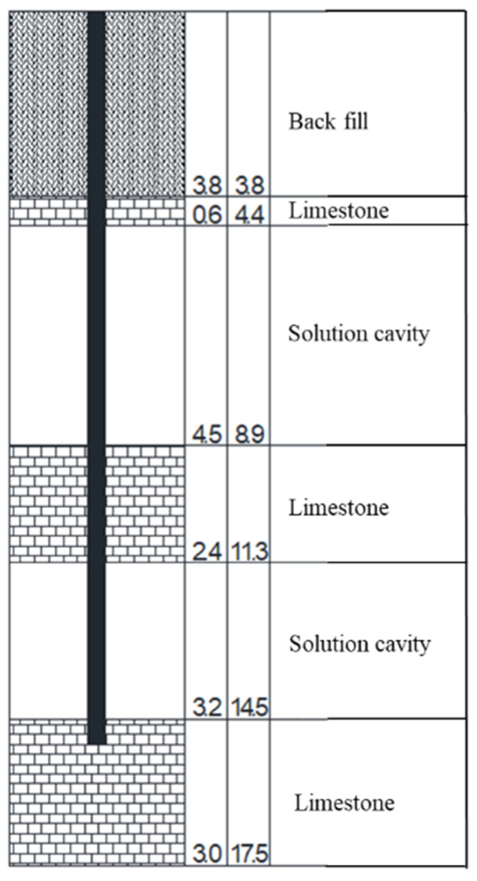
Figure 2.
(a)Static Load Q-s Curve, (b)Maximum settlement and increasing rate vs eccentricity ratio and (c) Bearing capacity and decreasing rate vs eccentricity ratio of PHC800AB130.
Figure 2.
(a)Static Load Q-s Curve, (b)Maximum settlement and increasing rate vs eccentricity ratio and (c) Bearing capacity and decreasing rate vs eccentricity ratio of PHC800AB130.
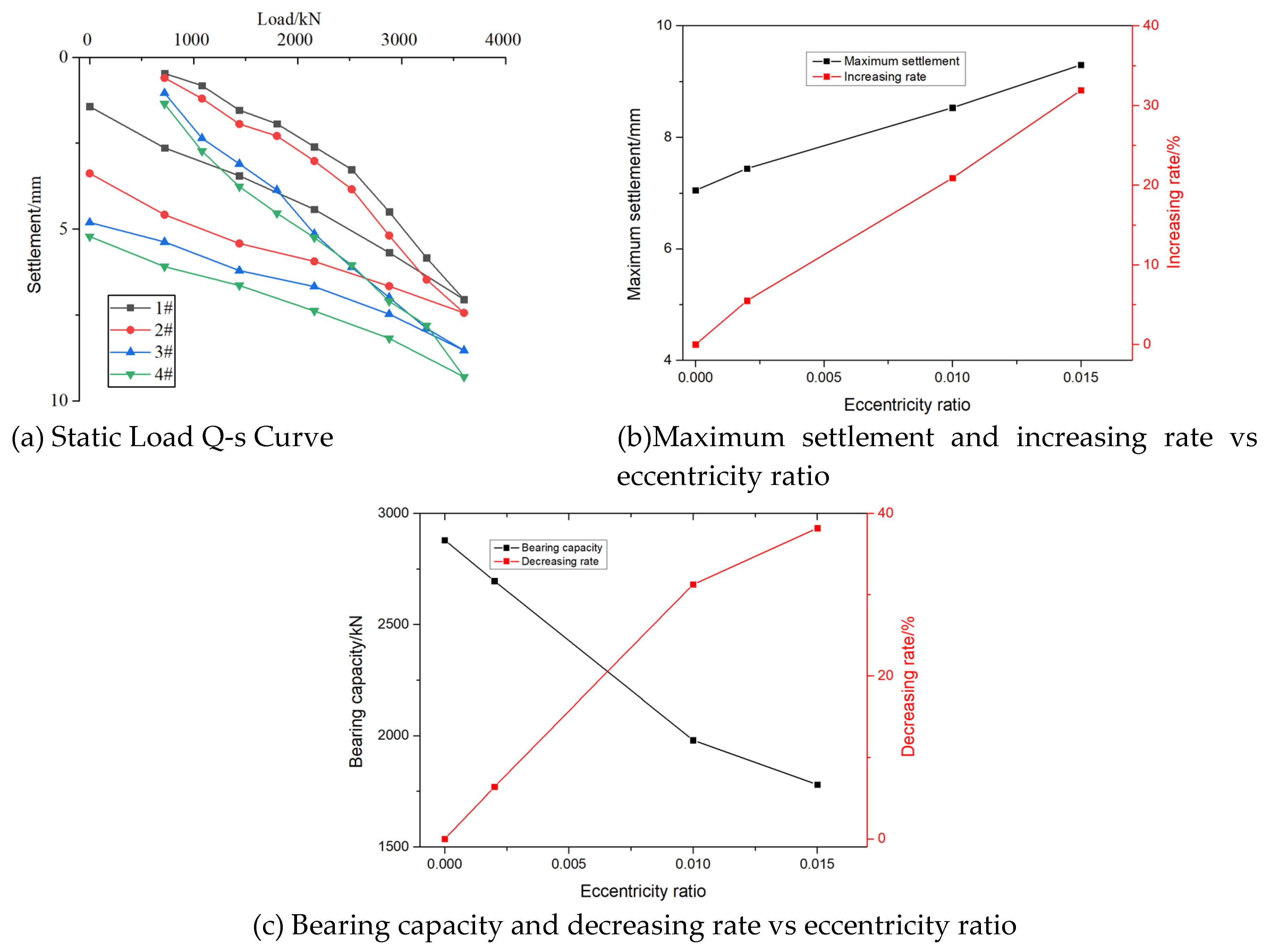
Figure 3.
Finite element model.
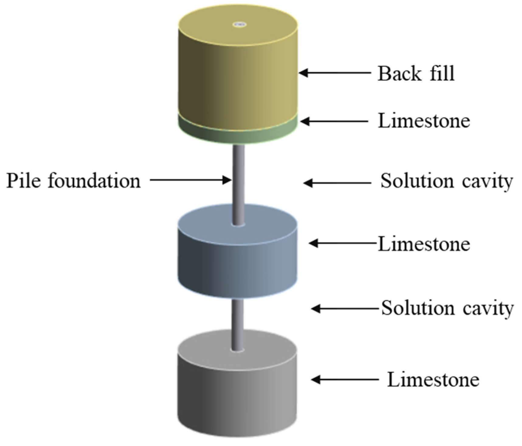
Figure 4.
The settlement of pile foundation with eccentricity of 0.015: Experimental test and Numerical simulation.
Figure 4.
The settlement of pile foundation with eccentricity of 0.015: Experimental test and Numerical simulation.
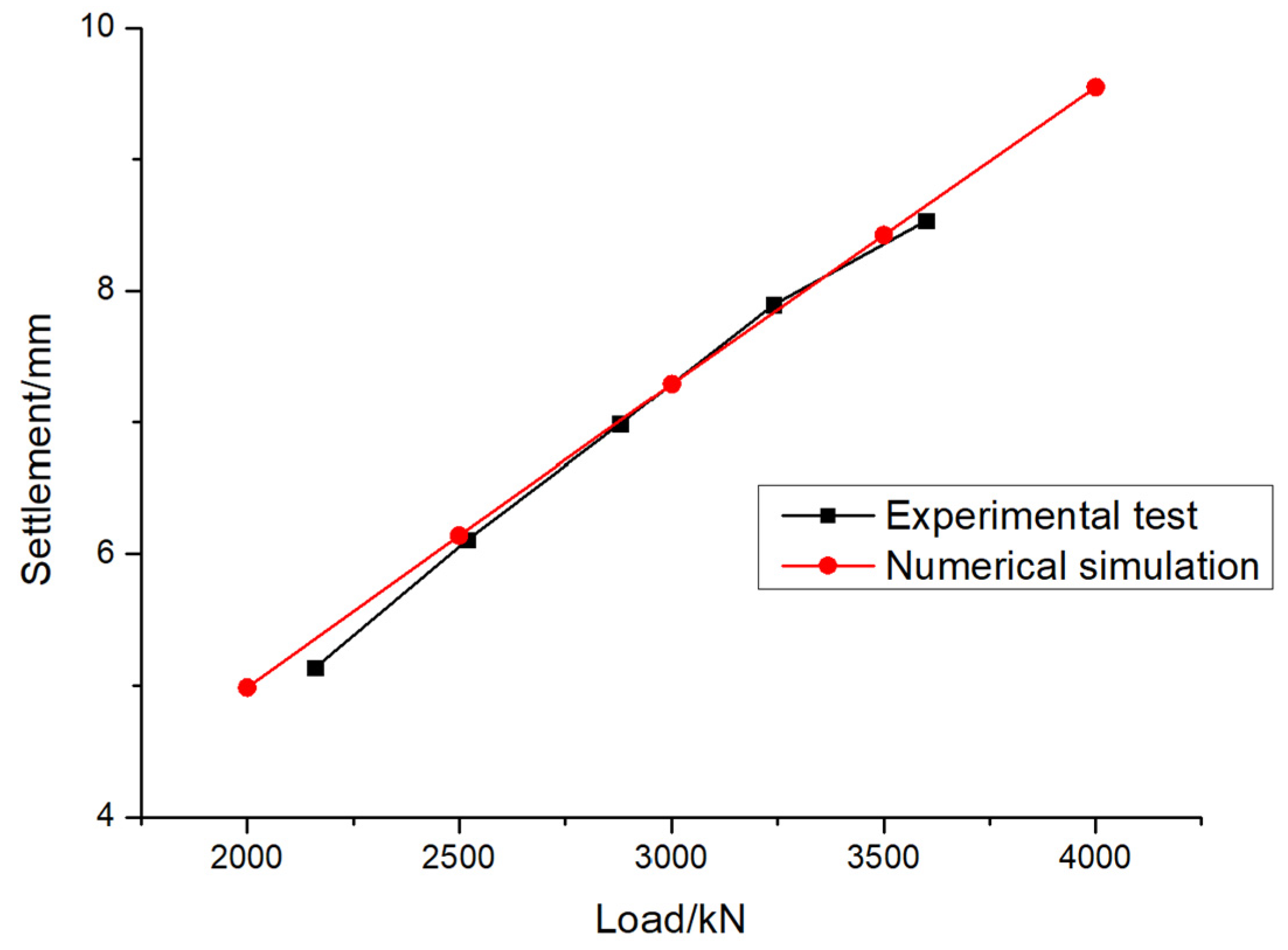
Figure 5.
The maximum displacement of pile foundations under different eccentricities and different loading forces.
Figure 5.
The maximum displacement of pile foundations under different eccentricities and different loading forces.
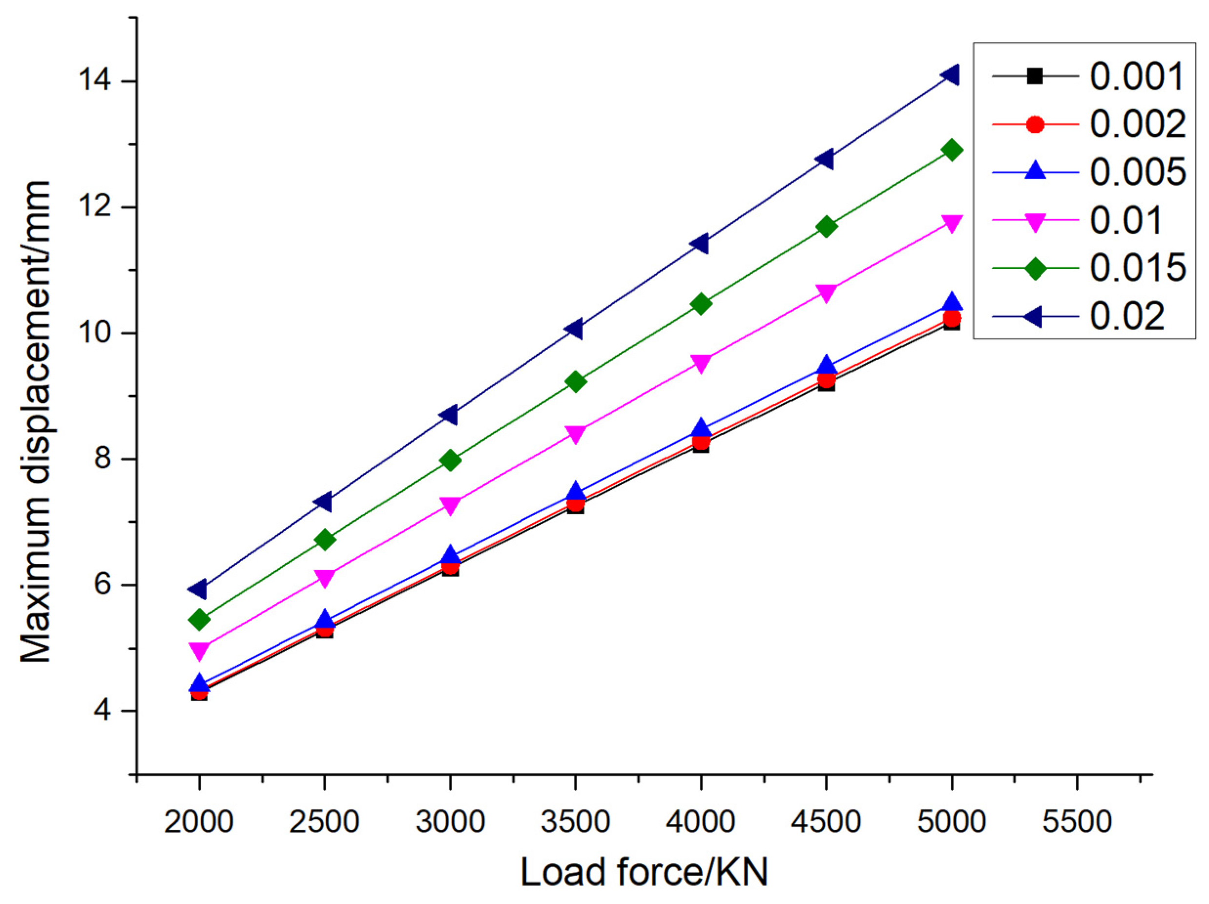
Figure 6.
The displacement contour of pile foundation under different eccentricities and different loading forces.
Figure 6.
The displacement contour of pile foundation under different eccentricities and different loading forces.
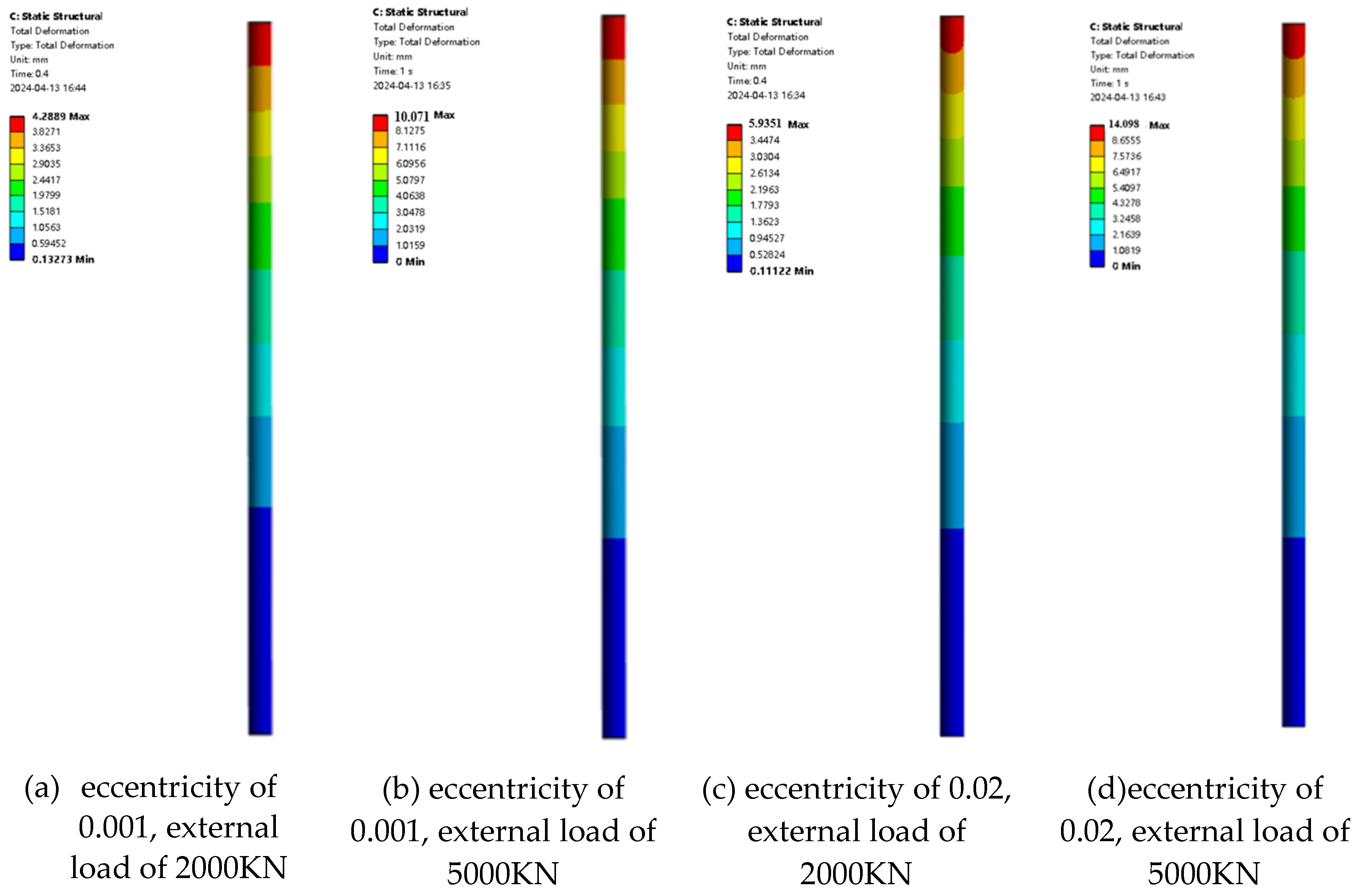
Figure 7.
The maximum stress of pile foundations under different eccentricities and different loading forces.
Figure 7.
The maximum stress of pile foundations under different eccentricities and different loading forces.
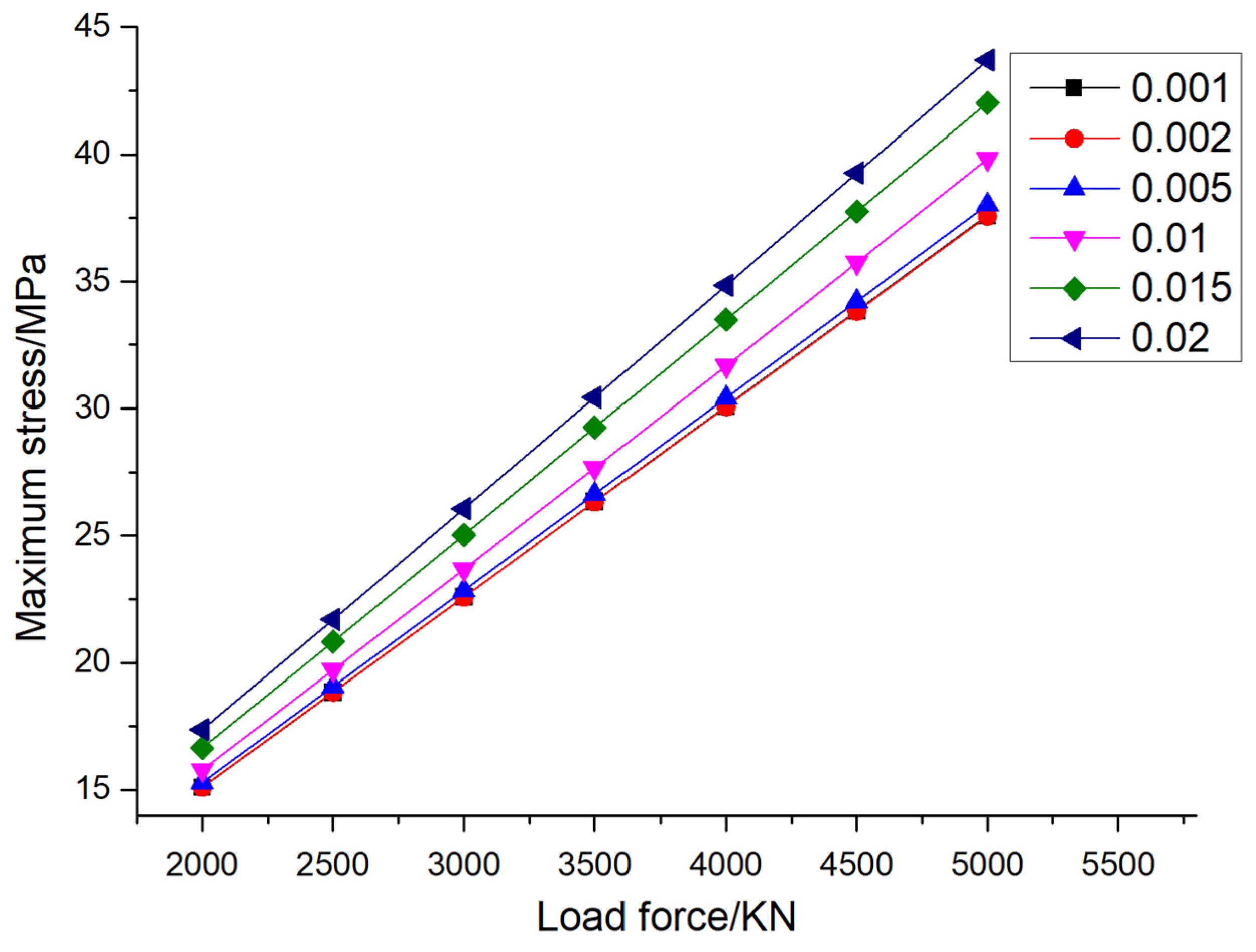
Figure 8.
The stress contour of pile foundation under different eccentricity and different loading force.
Figure 8.
The stress contour of pile foundation under different eccentricity and different loading force.
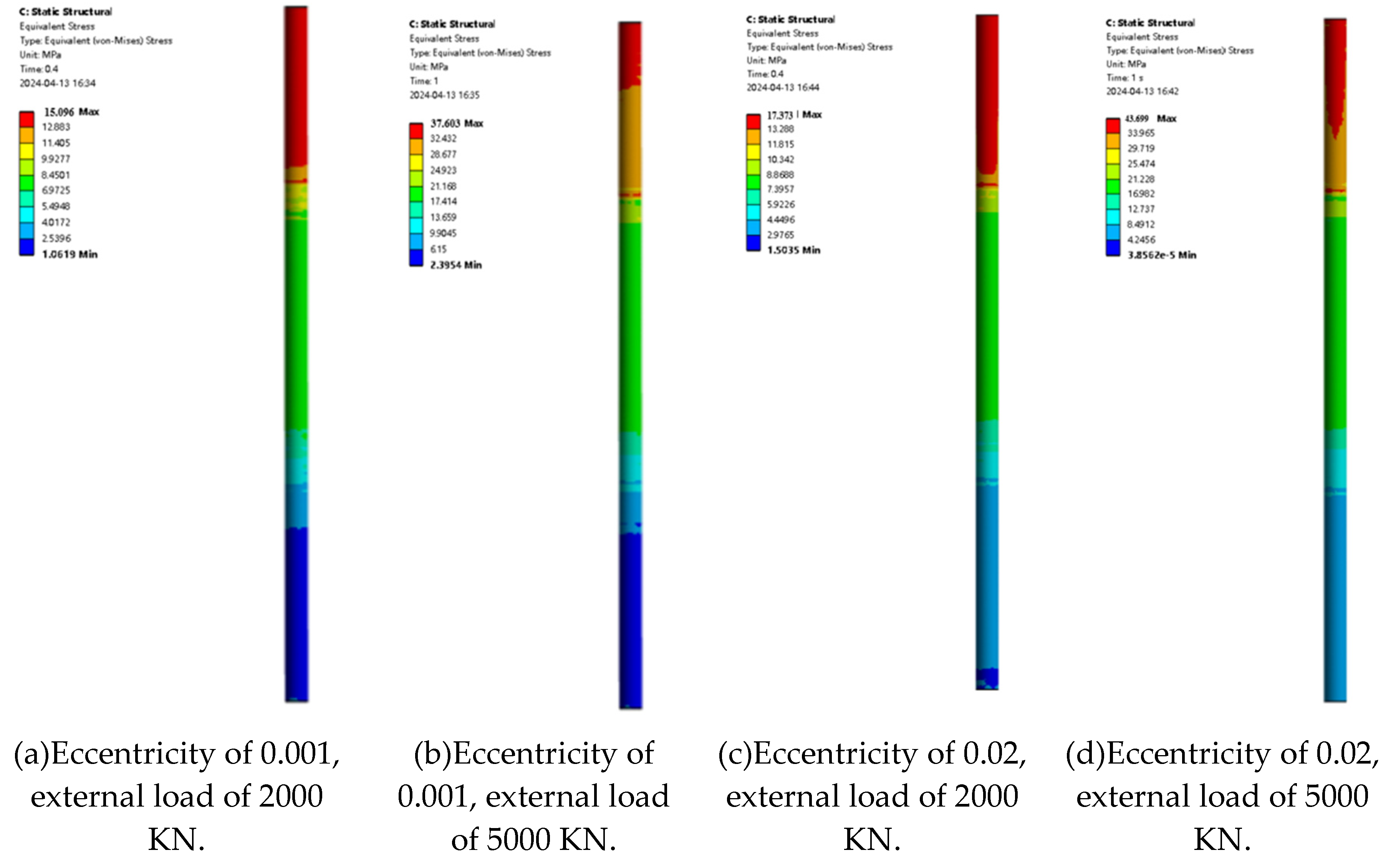
Figure 9.
The variation law of pile foundation displacement with eccentricity under design load.
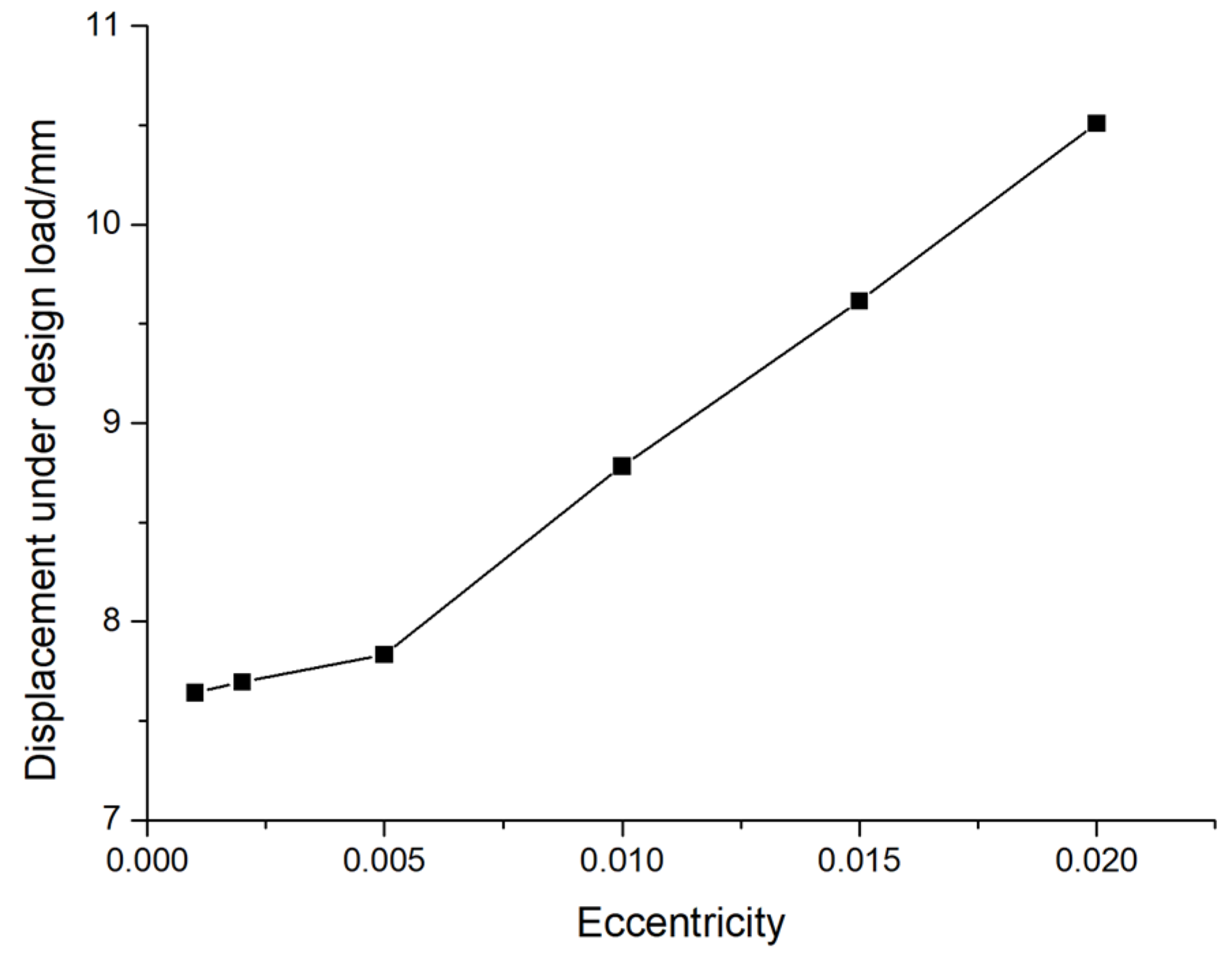
Figure 10.
The variation law of pile foundation stress with eccentricity under design load.
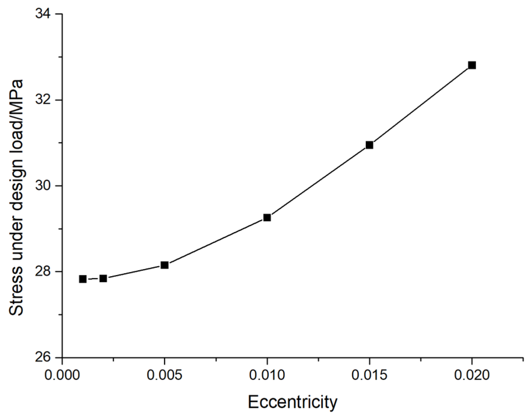
Figure 11.
The maximum displacement of pile foundations under different elastic moduli and different loading forces (the eccentricity is 0.005).
Figure 11.
The maximum displacement of pile foundations under different elastic moduli and different loading forces (the eccentricity is 0.005).
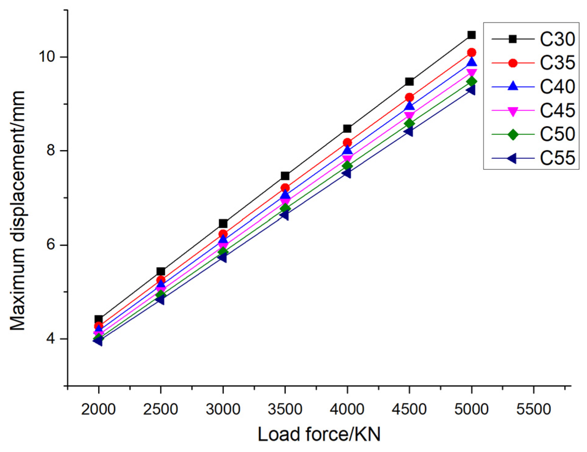
Figure 12.
The maximum stress of pile foundations under different elastic moduli and different loading forces (the eccentricity is 0.005).
Figure 12.
The maximum stress of pile foundations under different elastic moduli and different loading forces (the eccentricity is 0.005).
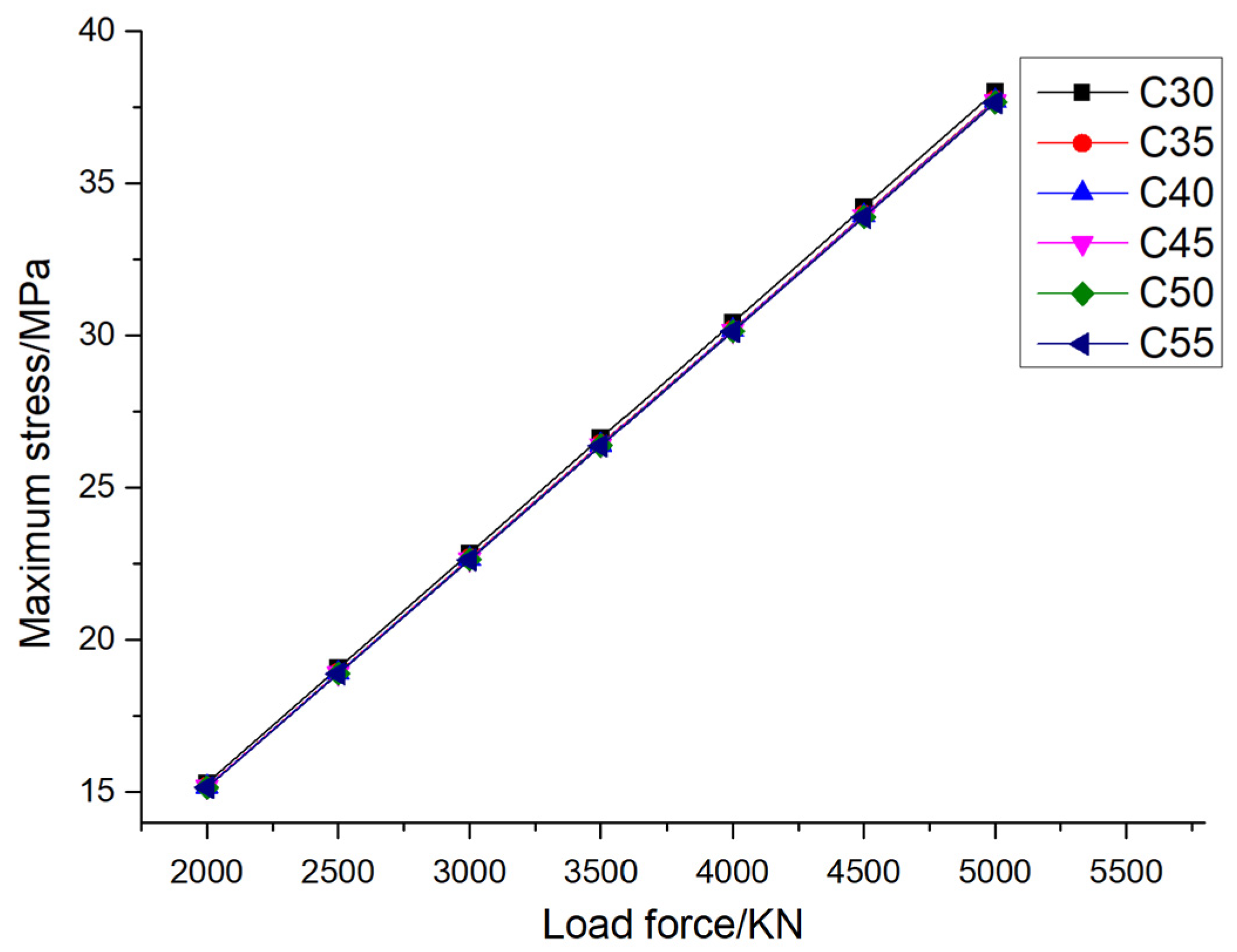
Figure 13.
The maximum displacement of pile foundations under different elastic moduli and different loading forces (the eccentricity is 0.01).
Figure 13.
The maximum displacement of pile foundations under different elastic moduli and different loading forces (the eccentricity is 0.01).
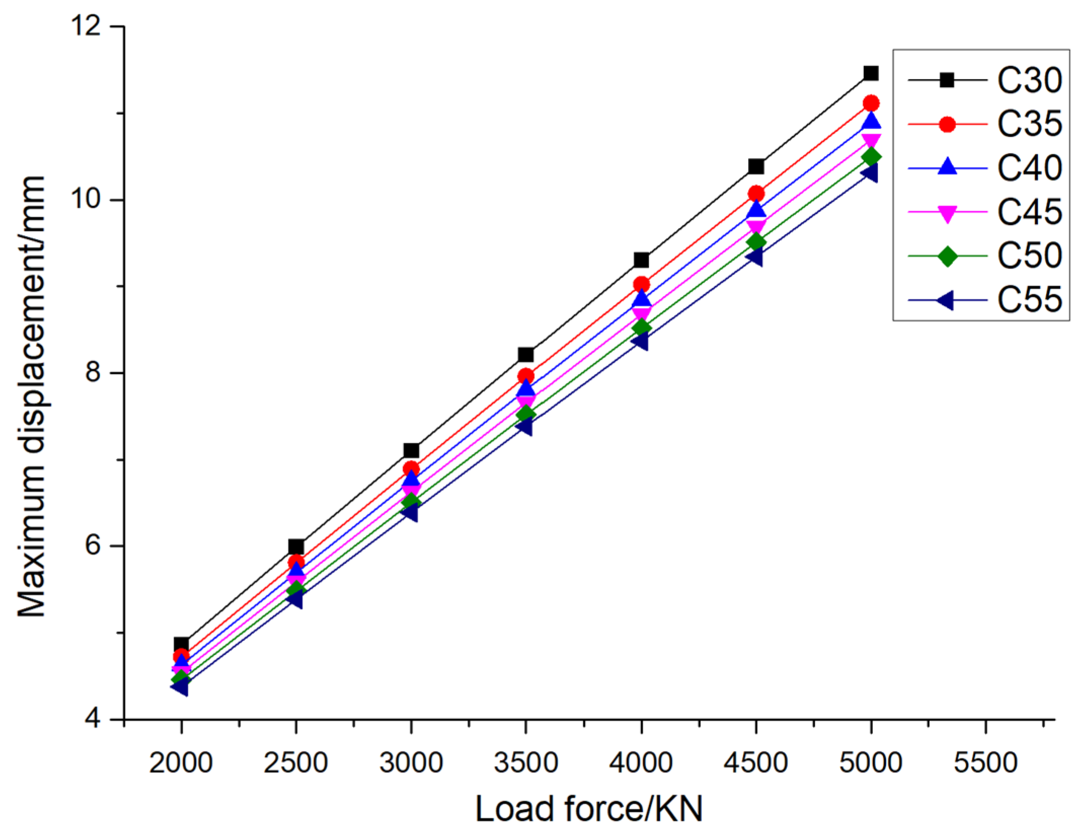
Figure 14.
The maximum stress of pile foundations under different elastic moduli and different loading forces (the eccentricity is 0.01).
Figure 14.
The maximum stress of pile foundations under different elastic moduli and different loading forces (the eccentricity is 0.01).
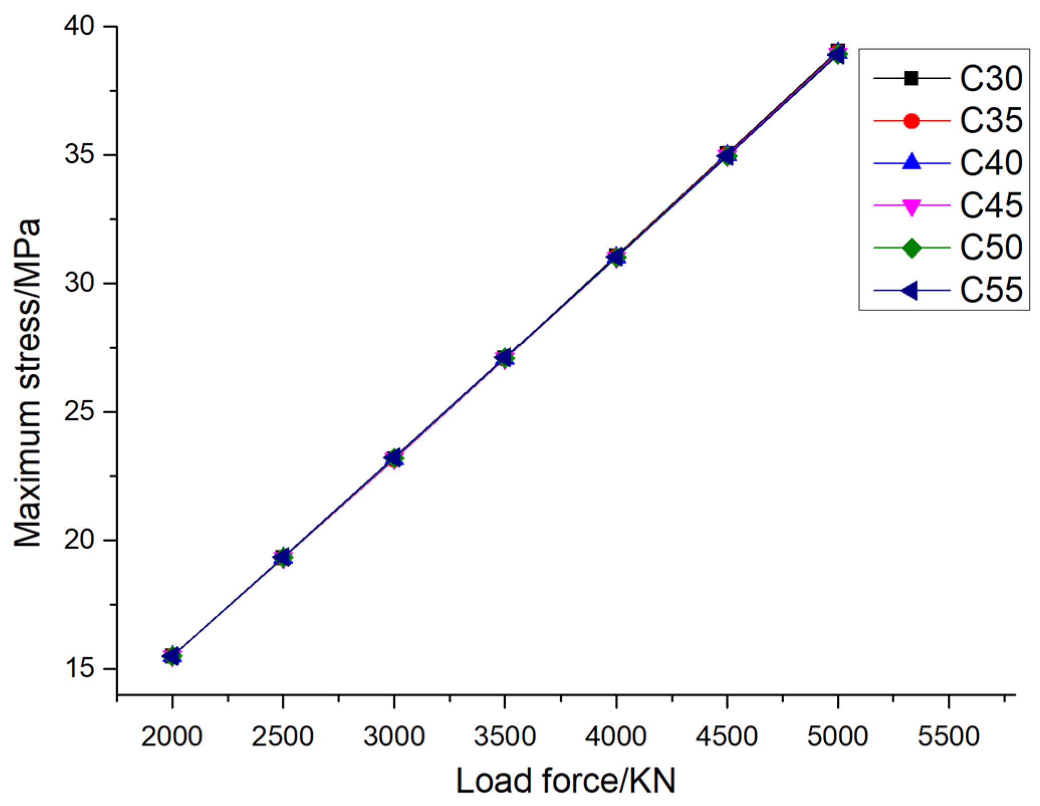
Figure 15.
The displacement contourof pile foundations under different elastic moduli and different loading forces (the eccentricity is 0.01).
Figure 15.
The displacement contourof pile foundations under different elastic moduli and different loading forces (the eccentricity is 0.01).
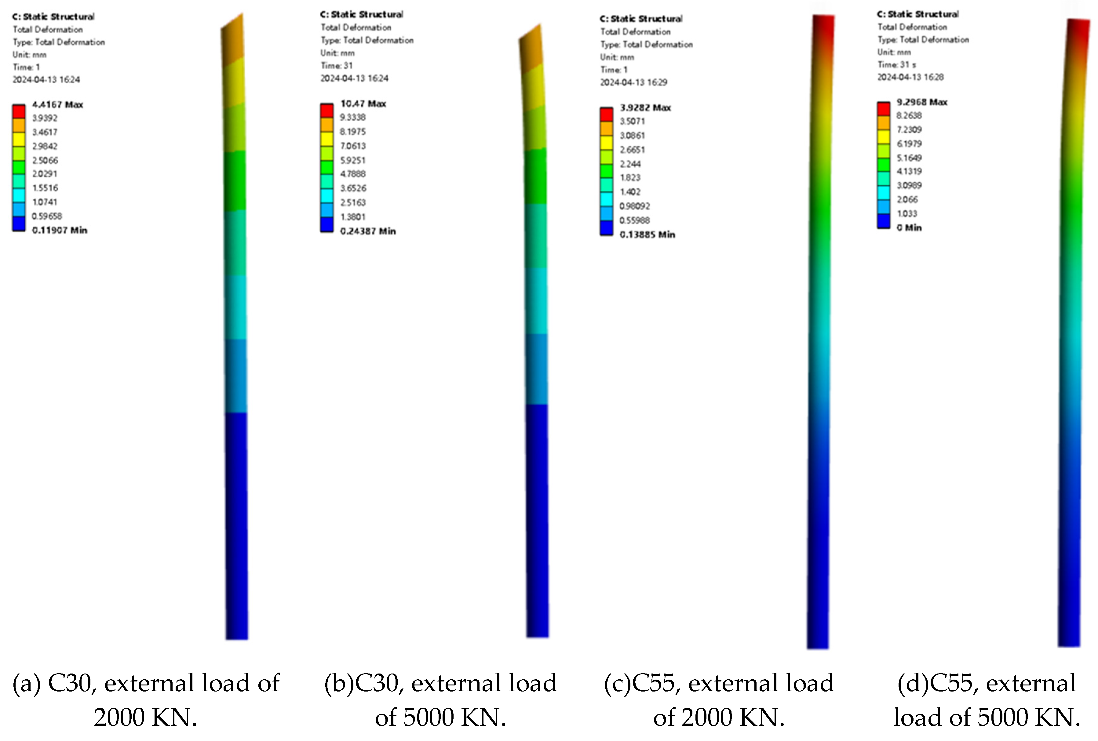
Figure 16.
The stress contour of pile foundations under different elastic moduli and different loading forces (the eccentricity is 0.01).
Figure 16.
The stress contour of pile foundations under different elastic moduli and different loading forces (the eccentricity is 0.01).
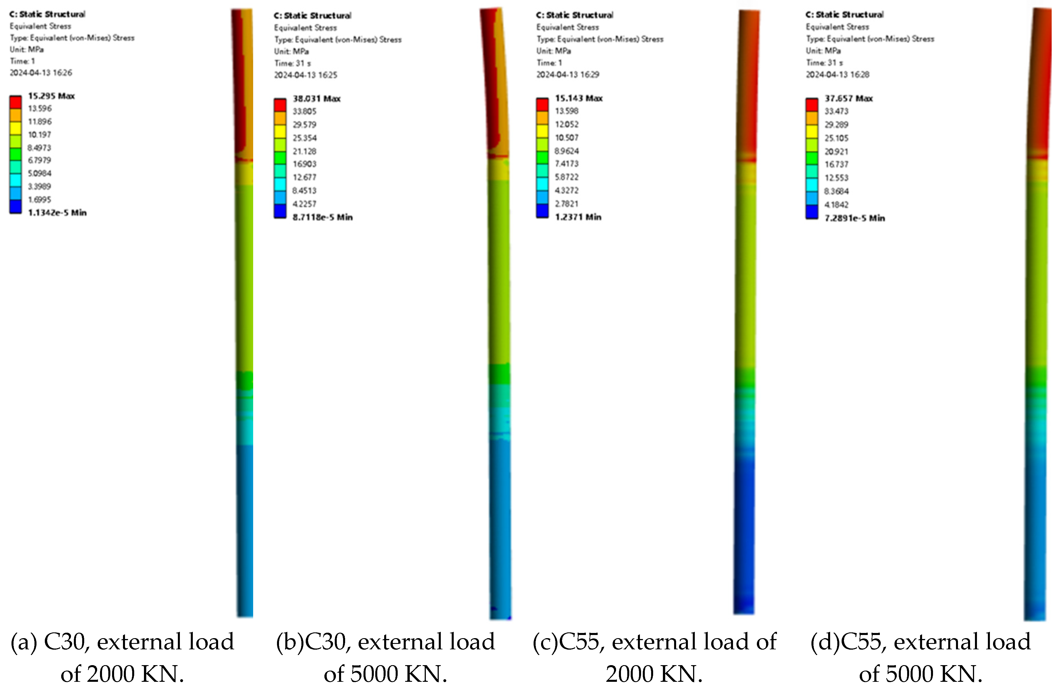
Figure 17.
The variation law of pile foundation displacement with concrete grade under design load.
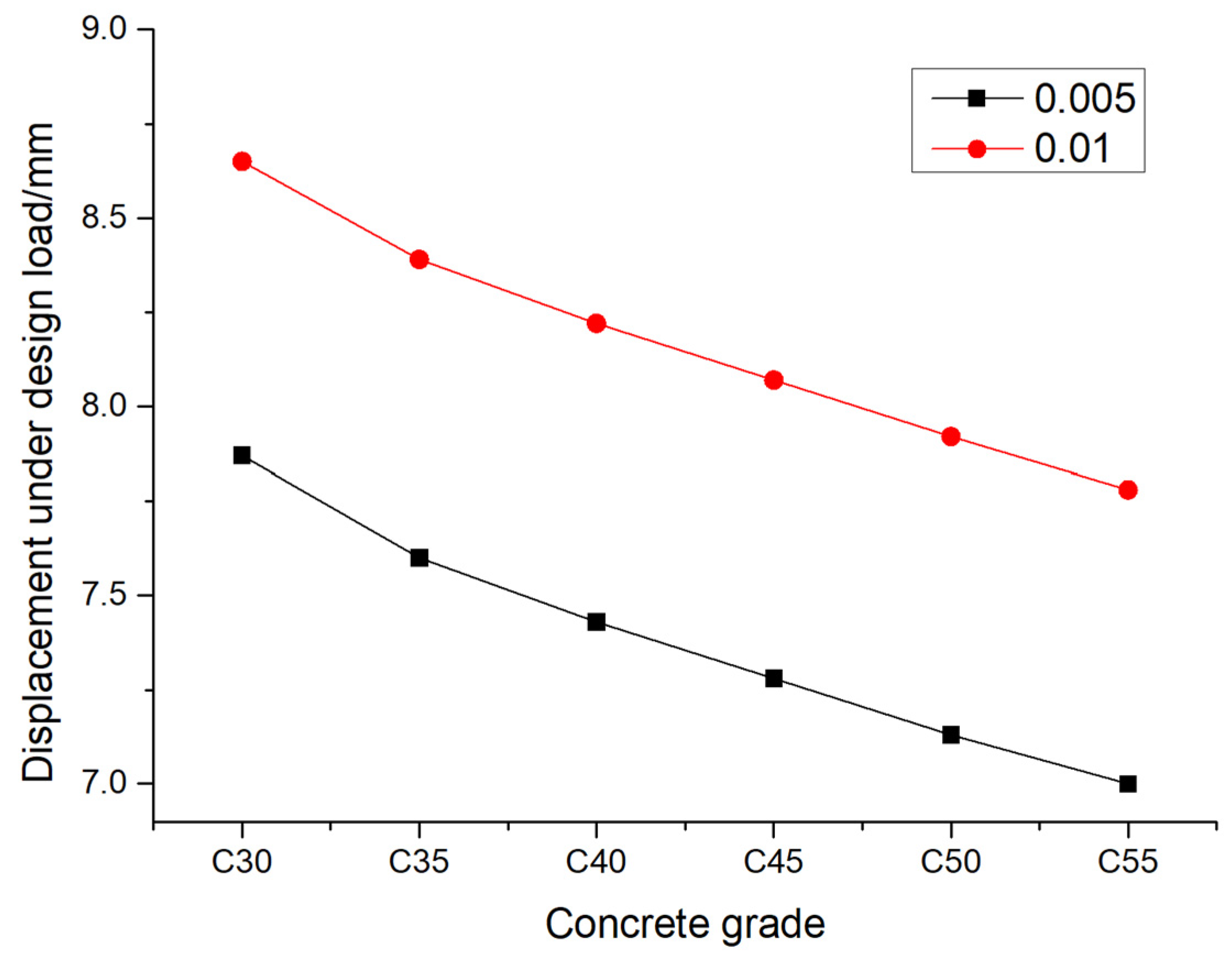
Figure 18.
The variation law of pile foundation stress with concrete grade under design load.
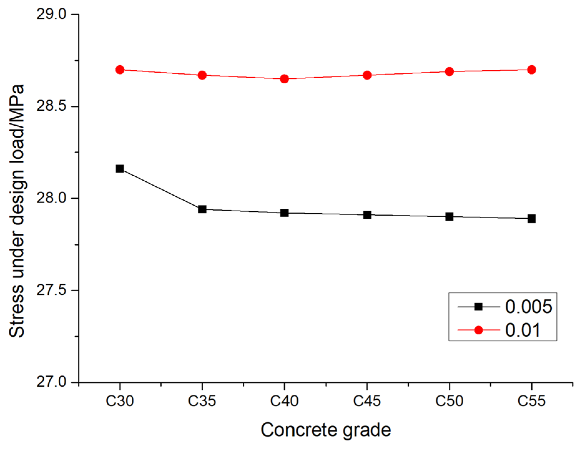
Figure 19.
The variation curve of the maximum displacement of pile foundation with the height of rock.
Figure 19.
The variation curve of the maximum displacement of pile foundation with the height of rock.
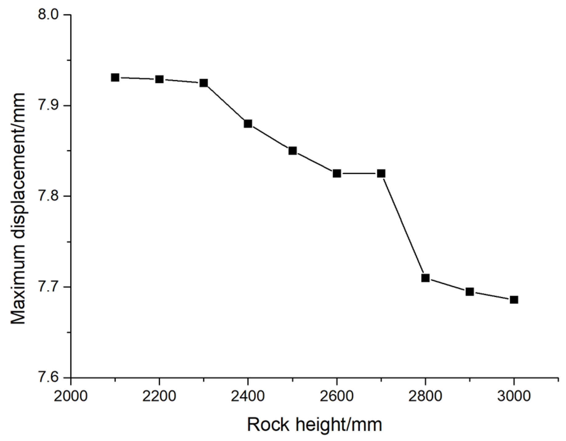
Figure 20.
The variation curve of the maximum stress of pile foundation with the height of rock.
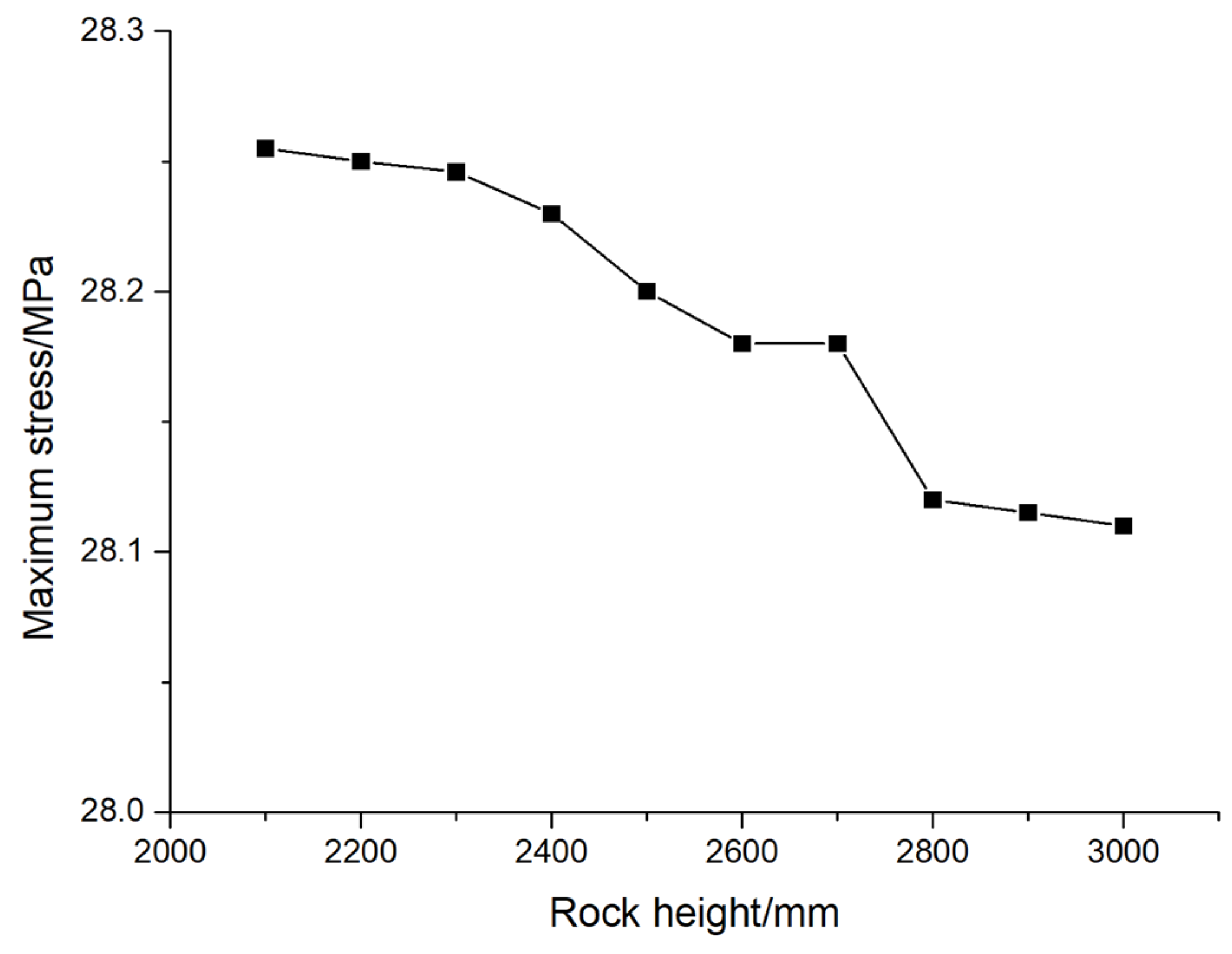
Figure 21.
The augmentation rate of (a) maximum displacement and (b) maximum stress of pile foundations under different eccentricities and different loading forces.
Figure 21.
The augmentation rate of (a) maximum displacement and (b) maximum stress of pile foundations under different eccentricities and different loading forces.
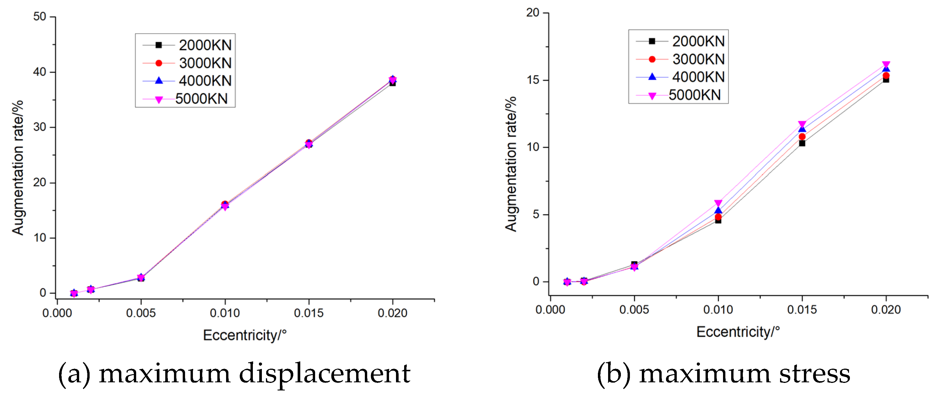
Figure 22.
The reduction rate of (a) maximum displacement and (b) maximum stress of pile foundations under different concrete grade and different loading forces.
Figure 22.
The reduction rate of (a) maximum displacement and (b) maximum stress of pile foundations under different concrete grade and different loading forces.
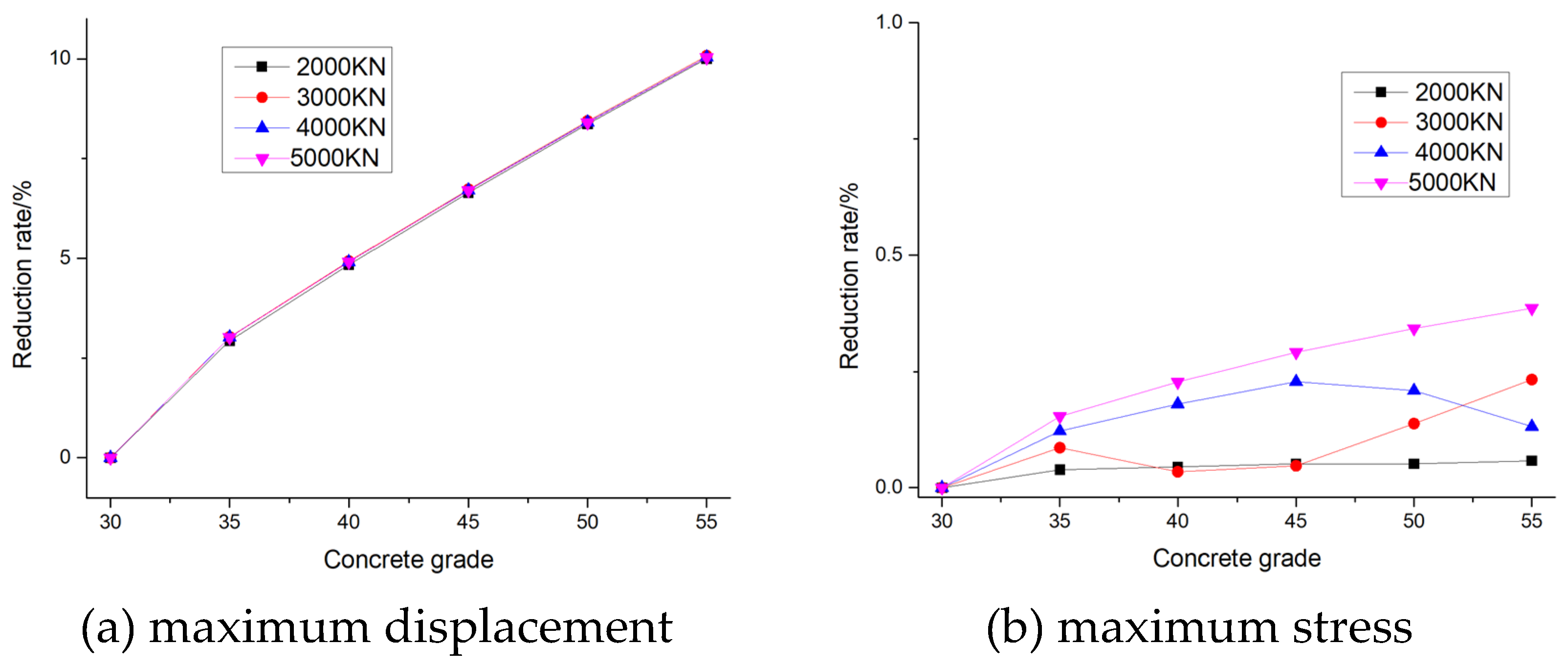
Figure 23.
The reduction rate of (a) maximum displacement and (b) maximum stress of pile foundations under different rock height.
Figure 23.
The reduction rate of (a) maximum displacement and (b) maximum stress of pile foundations under different rock height.
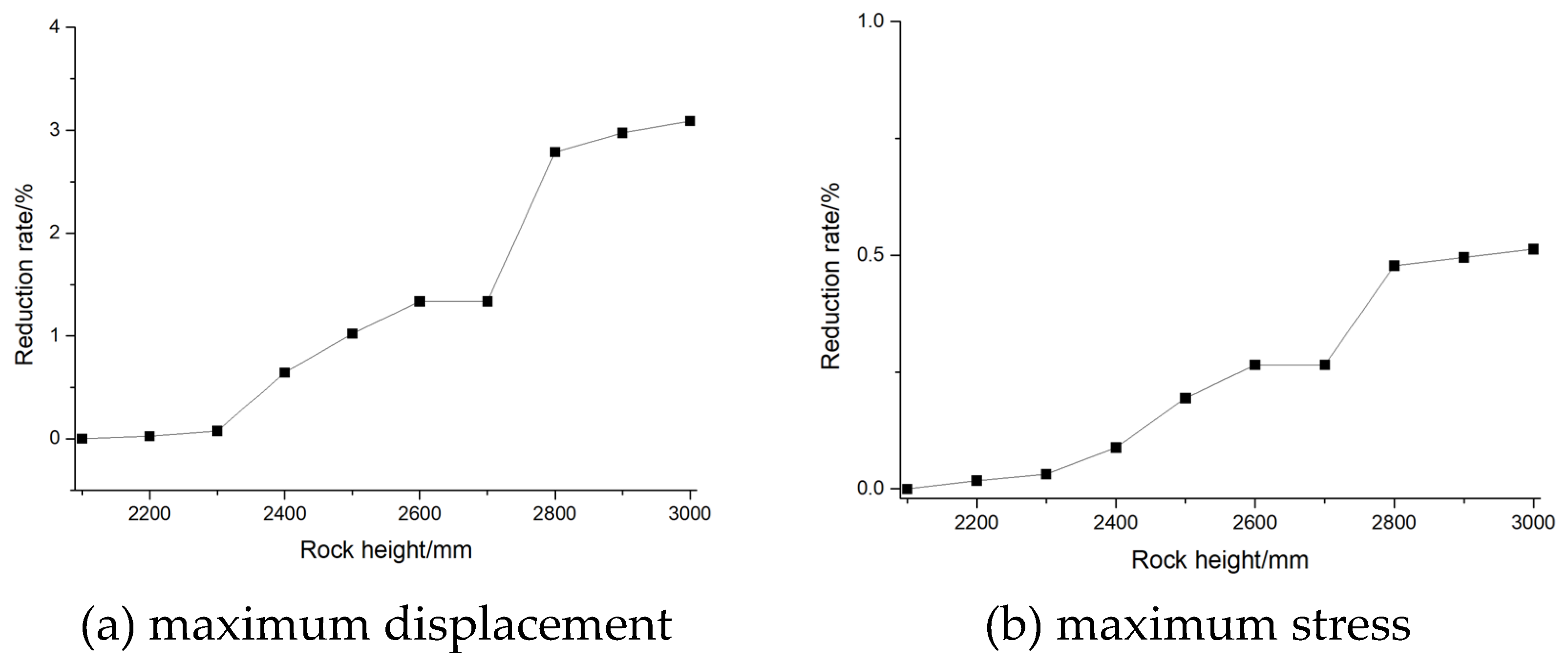

Table 1.
Material parameters used in numerical simulation.
| Material | (kg/m3) | E(Pa) | Cohesion (Pa) | Internal Frictional Angle (°) | |
|---|---|---|---|---|---|
| Concrete | 2500 | 3e10 | 0.3 | - | - |
| Back fill | 1580 | 3.5e7 | 0.27 | 1.78e4 | 30.2 |
| Broken limestone | 2700 | 3.2e9 | 0.275 | 1.5e6 | 45 |
| Limestone | 2700 | 5e9 | 0.275 | 2e6 | 45 |
Table 2.
Eccentricity and eccentricity distance.
| Eccentricity | 0.001 | 0.002 | 0.005 | 0.01 | 0.015 | 0.02 |
|---|---|---|---|---|---|---|
| Eccentricity distance/mm | 15 | 30 | 75 | 150 | 225 | 300 |
Table 3.
Concrete strength grade table for pile foundations.
| Strength grade | C30 | C35 | C40 | C45 | C50 | C55 |
|---|---|---|---|---|---|---|
| Elastic modulus(Pa) | 3e10 | 3.15e10 | 3.25e10 | 3.35 e10 | 3.45 e10 | 3.55 e10 |
Disclaimer/Publisher’s Note: The statements, opinions and data contained in all publications are solely those of the individual author(s) and contributor(s) and not of MDPI and/or the editor(s). MDPI and/or the editor(s) disclaim responsibility for any injury to people or property resulting from any ideas, methods, instructions or products referred to in the content. |
© 2024 by the authors. Licensee MDPI, Basel, Switzerland. This article is an open access article distributed under the terms and conditions of the Creative Commons Attribution (CC BY) license (http://creativecommons.org/licenses/by/4.0/).
Copyright: This open access article is published under a Creative Commons CC BY 4.0 license, which permit the free download, distribution, and reuse, provided that the author and preprint are cited in any reuse.


