1. Introduction
Ventricular Assist Devices (VADs) are life support mechanisms for patients with heart failure (HF). According to the American Heart Association (AHA), HF is a chronic and progressive condition in which the diseased organ cannot pump enough blood to meet the body's demands for oxygen and nutrients. One of the treatment options for such cases is the use of VADs [
1]. One indication for these devices is to assist the left ventricle of the patient's heart when the disease impairs it and cannot meet the physiological demands of the cardiovascular system to supply the body's needs [
2].
According to Teuteberg, VADs are recommended for three different objectives [
3]:
Bridge to Transplant (BTT) to maintain circulation at physiological levels until a transplant can be performed.
Bridge to Recovery (BTR) uses devices for myocardial recovery.
Destination Therapy (DT) when the patient is not eligible for a transplant.
In cases where the implantation of VADs is indicated, it is essential to clarify that the patient becomes entirely dependent on the proper functioning of the device; that is, anomalies in the VAD can result in the patient's death. In this context, VADs can be classified as belonging to the category of Critical Systems (CS).
The CS can be defined as a class of systems where a critical failure can cause unacceptable harm to people, the environment, and material or property damage, leading to significant economic losses. Therefore, critical failures are related to the occurrence of undesirable and unacceptable consequences that can increase the risk of severe damage to these systems [
4].
Therefore, it becomes evident that the concept of CS can be extended to the healthcare field, mainly using VADs as a treatment alternative for patients involving the three previously presented objectives. In the context of a patient with an implanted VAD, the critical element is the human being, and depending on the undesirable situations that may occur, recurrent hospitalizations can be triggered, as well as a risk of death for a specific patient profile due to the damage caused by the inadequate functioning of the VAD.
Although improvements in survival rates and complication reduction have been observed using a VAD [
5], monitoring the patient's health status is limited to periodic consultations scheduled by the medical team and trips to the hospital for medical urgency. Therefore, the monitoring of the patient's health status and the functioning of the VAD are limited by the following factors:
The objective of this study is to propose an Open System for Supervising Critical Adverse Processes in Patients with Implanted Ventricular Assist Devices (OSCVAD) based on an event-driven modular framework that features both horizontal and vertical integration, as well as timers for tracking the patient care process. To achieve this, diagnostic models for Adverse Events (AEs) and intervention models based on Intervention Protocols determined by the competent medical teams are presented. The diagnostic models can provide information to the medical team to monitor the patient's health status in real-time. In contrast, the intervention models oversee actions the medical team recommends for interrupting an Adverse Process, linking timed control strategies based on the watchdog concept.
The article is structured in the following sections. In
Section 2, the complications associated with the use of VADs are described. In
Section 3, the proposed method and the modeling of the OSCVAD processes are presented.
Section 4 presents the models based on an example of an AE and the results. In
Section 5, the results are discussed, and finally, in
Section 6, the conclusions are presented.
2. Related Works
During circulatory support, unwanted situations can arise that impact the continuity of treatment and may result in harm to patients with implanted VADs. The different causes that can lead to patient harm are device failures and defects or Adverse Events (AEs). The functional deviations of the device refer to failures or defects that are limited to the device itself, and therefore, the concept of safety control for VADs is applied as a means of failure prevention and management [
9]. On the other hand, deviations in the patient’s physiological behavior are direct consequences of AEs, which can cause potentially fatal harm to the patient. Therefore, contributions to the identification and necessary therapeutic intervention should be presented. The following provides the contextualization of AEs and the risks associated with using VADs.
2.1. Adverse Events
In patients undergoing VAD implantation surgery, a significant improvement in survival and quality of life is observed. However, there remains a residual risk of mortality that must be managed. The occurrence of AEs has the potential to cause complications that may result in hospital readmission and death. Some likely AEs include bleeding, thrombosis, pulmonary embolism, stroke, infection, and device malfunction associated with coagulation issues, among others AEs [
10,
11].
In patients receiving VAD implantation surgery, a significant improvement in survival and quality of life is observed. However, there remains a residual risk of mortality that must be managed. The occurrence of AEs has the potential to cause complications that may result in hospital readmission and death. Some likely AEs include bleeding, thrombosis, pulmonary embolism, stroke, infection, and device malfunction associated with coagulation issues, among others AEs [
10,
11].
In a comparative study of two VADs during a chronological period, HeartMate2 (HM2) implanted in 512 patients and HeartMate 3 (HM3) implanted in 516 patients, the study refers to the most common AEs observed during the period [
11]. The following presents the AEs observed in the cited research, listed by their frequency of occurrence:
HM2: Infection (56.4%), Bleeding (55%), Cardiac arrhythmia (41%), Right heart failure (28.3%), Respiratory failure (19.4%), Stroke (19.4%), Device thrombosis (13.9%), Renal dysfunction (11.1%), Neurological event (9.3%), and Liver dysfunction (5.3%).
HM3: Infection (58.3%), Bleeding (43.7%), Cardiac arrhythmia (35.9%), Right heart failure (34.2%), Respiratory failure (21.6%), Renal dysfunction (14.2%), Neurological event (11.5%), Stroke (9.9%), and Liver dysfunction (4.9%).
2.2. Risks Associated with Adverse Events
It is well-known in the medical community that the increased risk of arrhythmias is associated with the implantation of VADs. Although arrhythmias are AEs that can be managed and their effects minimized with medications or medical interventions, if persistent, they may lead to hemodynamic disturbances, right ventricular failure, and organ dysfunction. Complications associated with arrhythmias can also result in recurrent hospitalizations and admissions and involve the risk of death or dangerous combinations of AEs [
14].
Starting in 2008, recurrent cases of device thrombosis were reported, leading to increased hospital readmissions due to complications from AEs. There are reports of surgeries for device extraction or replacement and cases of death during the evaluated period [
15,
16,
17]. It is suggested that hemodynamic disturbances be minimized when comparing axial flow devices with current devices through the modulation of flow in artificial pulsatile mode [
18]. However, as previously observed, an extensive list of AEs arising from interactions between the entities within the studied system can cause severe damage, indicating that risk should be assessed within the first few months after implantation.
From 2015 to 2019, the occurrence of 'early AEs' was the main complication in the postoperative period within the first 90 days after implantation and could extend into the 12 months of treatment or more as 'late AEs.' During the observed period, bleeding and infection were the most common causes of hospital readmission [
3,
19].
Patient follow-up with implanted VADs is conducted through medical consultations and examinations. Medical Devices Reporting (MDR) is submitted by medical centers based on complaints reported during treatment or observations made by patients who perceive the effects caused by AEs. Although the medical team monitors patients, there is no real-time monitoring of the VAD, which may result in delayed identification of AEs, given the need for in-person medical evaluation [
6,
7,
8,
20,
21].
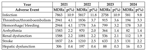
Table 1 presents a compilation of MDRs for complications associated with AEs over the past four years. The observed percentage was calculated based on the total number of MDRs reported annually, as follows: 2021 (71,882), 2022 (49,358), 2023 (25,311), and 2024 (5,958) [
22].
Another aspect that should be addressed is the contribution of urgent care services in treating HF, considering that the patient may sometimes be referred to the urgent care service, requiring appropriate care with reduced waiting times [
23]. For risk stratification, clinical scores are suggested to assist the medical team in risk prevention and the decision-making process during treatment, with the following as an example:
EHMRG Score - suggested for better risk stratification of acute heart failure in the emergency department and can inform physicians about decisions regarding patient admission or early discharge [
24].
CHA2DS2-VASc Score - suggested for predicting the risk of ischemic stroke and subsequently guiding the use of oral anticoagulation in patients with non-valvular atrial fibrillation [
25].
HAS-BLED Score - suggested for predicting bleeding risk in patients with atrial fibrillation [
26].
2.3. Complexity of the System: VAD, Patient, and Medical Team
Based on the context provided regarding patients with an implanted VAD, a complexity is observed resulting from the interaction among three fundamental entities: the VAD, the patient, and the medical team. The following presents some of the characteristics of this system formed by the patient, VAD, and medical team, considering the described interactions and the complexity principles explored in [
27,
28].
Interactivity: The system involves the participation of the ‘VAD’ and its subsystems (blood pump, cannulas, controller, driveline, and power supply), the ‘patient’ and their various subsystems (composed of organs, tissues, and cells that interact with each other), and the ‘medical team,’ which interacts with the other two elements to monitor and supervise processes that may occur in the patient.
Adaptability: The system is dynamic, and changes in behavior are driven by interactions between the entities that constitute it.
Non-deterministic: The system's response is unpredictable, and its behavior is stochastic, meaning the phenomena observed in the system are random and non-deterministic.
After examining the characteristics of the studied system, the diversity of processes related to the domains of operation and interaction between the VAD, the patient, and the medical team entities stands out. Fundamentally, it is considered that the studied system is open because it continuously communicates with the external environment [
29] and that it presents complexity due to the distinctive nature of the interactions between the entities that constitute it [
27,
28]. Different contexts may involve different interactions between the entities involved; therefore, there are different processes throughout the patient's life cycle with an implanted VAD. The mentioned system behaves like a Discrete-event system (DES), meaning its state evolution is entirely dependent on the occurrence of discrete asynchronous events over time [
30].
2.4. Formalisms for Process Modeling of Complex Systems
The Petri Nets (PNs) are formal tools for modeling the behavior of Discrete-event Systems (DES). They enable modeling dynamic behaviors involving parallelism, concurrency, asynchrony, and non-determinism [
29,
31]. Various classes of Petri Nets can be applied for process modeling; however, Interpreted Petri Nets were chosen [
32]. Notably, the Production Flow Schema (PFS) is a high-level unmarked class of Petri Nets, known as Channel-Agency Nets [
33], designed to address the limitations of 'one-step design' techniques for modeling complex systems. The PFS allows for the graphical representation of processes as sequences of steps that represent activities interconnected through distributor elements.
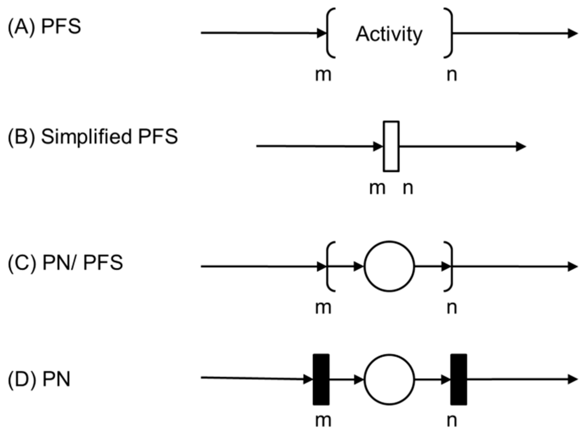
In this context, the PFS is a bipartite graph composed of activity elements (active elements capable of performing transformations, such as actions or task execution), distribution elements (passive elements that do not perform transformations but can collect, accumulate, storing, and distributing items), and directed arcs to connect the 'activities' and 'distributors' elements. The graphical representation of the essential elements that make up a PFS graph is presented in
Figure 1.
The PFS diagrams serve as a basis for generating models in various classes of PNs [
34], such as the interpreted PNs mentioned earlier [
32]. Each activity in a PFS can be detailed into elements of a PN as represented as follows.
Figure 2 (A) presents the initial activity of the PFS, which will be detailed in a condition-event Petri Net, for example.
3. Proposed Supervision System and Method for Process Modeling
3.1. OSCVAD
The proposed Open System for Supervising Critical Adverse Processes in Patients with Implanted Ventricular Assist Devices (OSCVAD) features a structure that enables both horizontal and vertical integration, which are fundamental characteristics for implementing a system that aligns with the level of complexity present in its dynamic behavior.
Concerning horizontal integration, the structure was proposed to support the dispersion among the entities that comprise the OSCVAD, as they are not required to be in the same geographical locations. In other words, the patient may or may not be in the hospital, and medical attendance may not necessarily be required for a particular event. Furthermore, the proposed structure is event-driven and supports vertical integration among the modules and entities of the OSCVAD to provide patient assistance through monitoring of undesirable events and execution of necessary mitigation activities. The medical team schedules mitigation activities based on their knowledge, and they specify the essential actions and how the mitigation activities should be conducted to interrupt an Adverse Process
1.
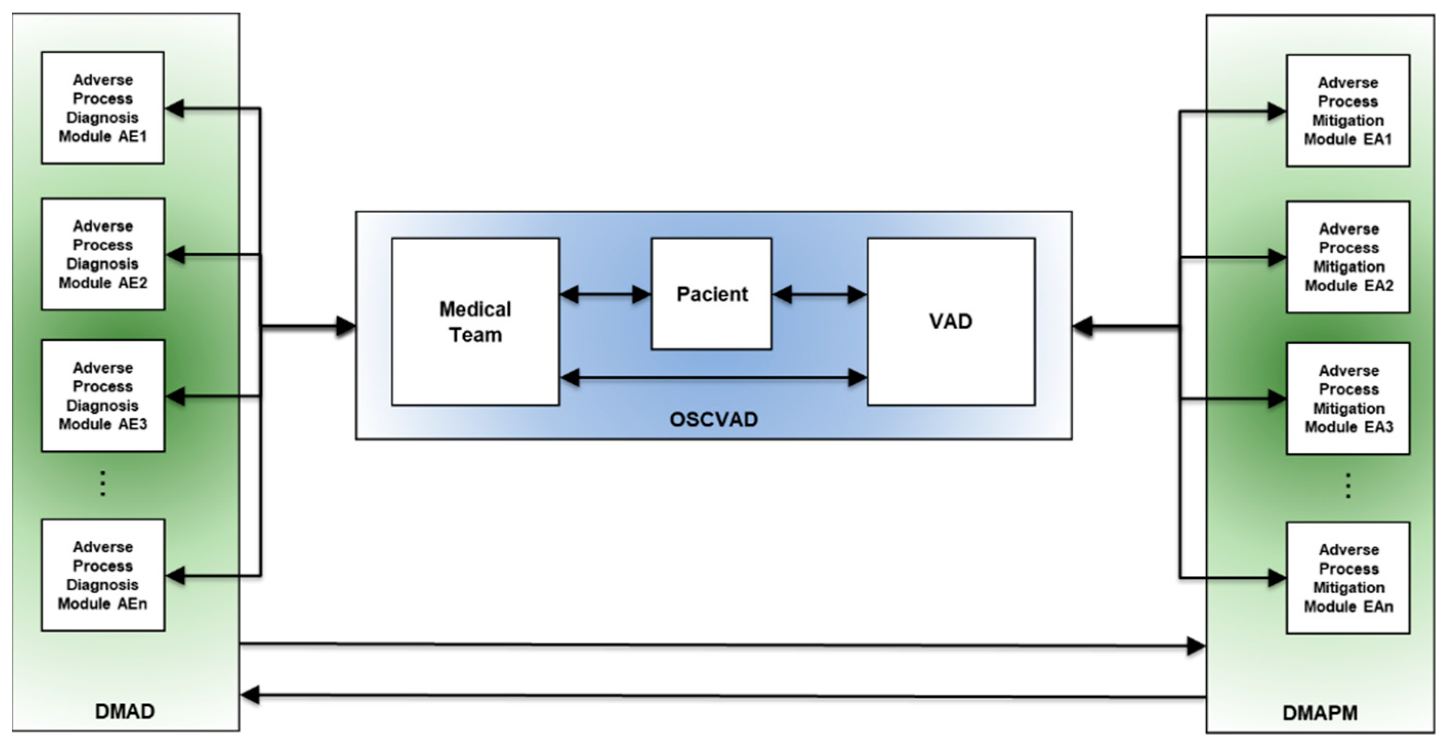
Figure 3 illustrates three interconnected blocks with bi-directional flow, representing their interaction. The horizontal communication interface between the physical objects corresponding to the VAD entities, patient, and medical team is provided in blue. In green on the left, a modular structure called the Digital Model for Adverse Event Diagnosis (DMAD) is represented, and each module is developed to identify a specific AE and its consequences. The role of the DMAD is to provide the medical team with two main pieces of information:
In green on the right, another modular structure, the Digital Model for Adverse Process Monitoring (DMAPM), is represented. In each module, mitigation activities for a specific Adverse Process are specified. The use of the DMAPM enables two crucial functionalities:
Supervision of mitigation actions.
Dynamic monitoring of executed mitigation activities; and
Supervision of mitigation activities that are yet to be executed.
As shown in
Figure 3, the function of each item is as follows: the item on the left is the Digital Model for Adverse Event Diagnosis (DMAD), the item on the right is the Digital Model for Adverse Process Monitoring (DMAPM), and the item in the center represents the horizontal integration among the entities that constitute the OSCVAD.
3.2. Definition of OSCVAD Processes
This section defines fundamental aspects of contextualizing adverse processes. Initially, in 3.2.1, a method for structuring processes involving the domains of operation and interaction among them is presented to delineate different operational contexts defined by regions susceptible to the occurrence of AEs. Subsequently, 3.2.2 introduces the necessary steps for modeling Adverse Processes.
3.2.1. Method for Structuring Processes of the OSCVAD
Based on the previously presented definition of OSCVAD, which involves the horizontal and vertical interaction among the three entities (VAD, Patient, and Medical Team), and considering that each entity has autonomous and dynamic behavior inherent to each operational context, there are unique characteristics that are requirements and need to be highlighted:
The ‘VAD,’ the patient, and the medical team have telemetry resources to enable communication among the entities via an onboard control system or through mobile devices.
The ‘Patient’ has physiological control and regulation mechanisms to maintain homeostasis.
The ‘Medical Team’ has the necessary expertise to monitor the patient's progress and conduct appropriate therapeutic interventions, particularly regarding the occurrence of AEs and the complications they may cause.
In this way, it becomes evident that an inherent complexity is associated with the dynamic interaction possibilities among the three entities. If reductionist techniques that do not address this dynamic reality are applied, the patient's health status may be compromised, potentially leading to a life-threatening condition.
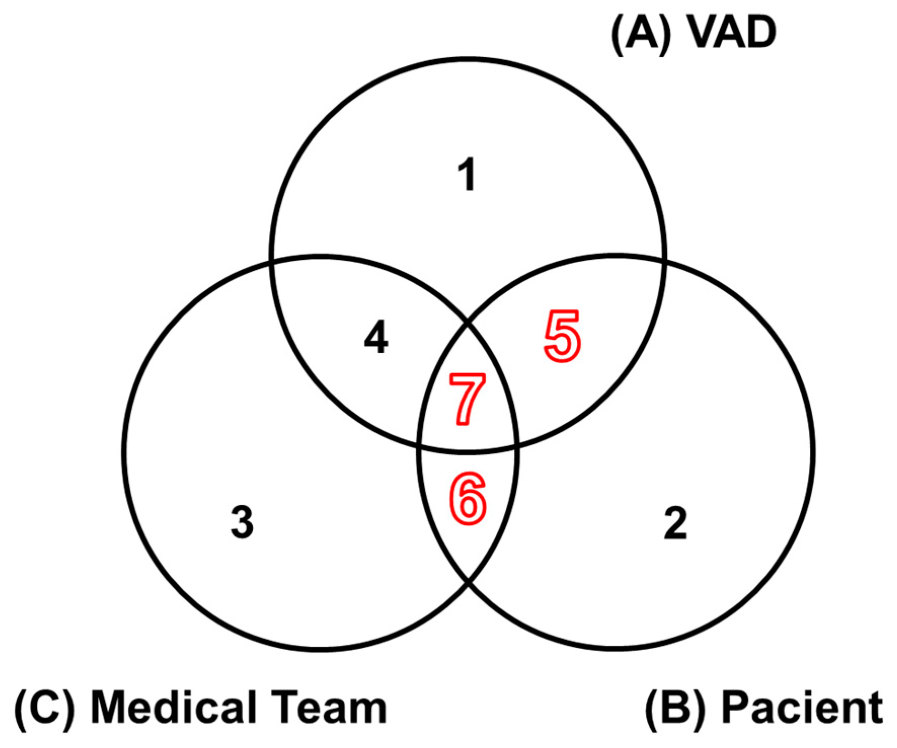
The model illustrated in
Figure 4 was proposed to structure the processes of the OSCVAD, delineating different operational contexts of the entities and their interactions. Sets A, B, and C are designated to represent the operational domains of each entity. The numbered regions from 1 to 7 are detailed. The red-highlighted numbering indicates the regions where the context of AEs applies, according to the proposal of this work.
The following describes the seven regions with distinct semantics:
Region 1: Each element in this region of set A represents processes associated with the VAD in the context of its local control system, including the device for processing embedded control algorithms, sensing devices, actuators, and integration with supervisory systems. Therefore, the concept of AEs does not apply in this region, as events may occur associated with potential failures of various natures.
Region 2: Each element in this region of set B represents physiological processes inherent to the behavior of the Patient’s cardiovascular system. It is precisely in this context that AEs may occur, and it is essential to note that AEs occurring in this region are not necessarily related to the other entities.
Region 3: Each element in this region of set C represents issues with the Medical Team unrelated to the Patient; therefore, the concept of AEs does not apply here.
Region 4: Each element in this intersection region between A and C, without the Patient, corresponds to processes involving the proper selection of a VAD for a specific Patient profile, as well as the setup of operating conditions according to this profile. Therefore, the concept of AEs does not apply in this context, as the Patient is absent.
Region 5: Each element in this intersection region between A and B, without the Medical Team, corresponds to processes involving direct interactions between the Patient and their VAD, where the concept of AEs applies.
Region 6: Each element in this intersection region between B and C, without the VAD, corresponds to possible medical interventions by the Medical Team that involve Patient care before the VAD implant or during its use, occurring throughout the Patient's life cycle. Therefore, AEs occurring in this region are associated with medication use.
Region 7: Each element in this intersection region between A, B, and C represents processes involving direct interaction among the entities, meaning that AEs occurring in this region are necessarily linked to the other entities, including the Patient, and therefore the concept of AEs applies.
3.2.2. Modeling of OSCVAD Processes
The processes are defined within the event-oriented modular structure presented in
Figure 3 to address patient needs based on OSCVAD specifications. For each process, two modules are specified: one represents the evolution of undesirable states following the occurrence of an Adverse Event (digitization of the Adverse Process), while the other focuses on actions recommended by the Medical Team for mitigating the Adverse Process. Three steps are planned for specifying modules that meet the requirements of an Adverse Process:
Step 1: Identification of risks associated with the occurrence of an Adverse Event.
Step 2: Development of the Adverse Process model.
Step 3: Development of Intervention Protocols.
In Step 1, for identifying risks associated with the occurrence of an AE, one of the techniques that can be utilized is Hazard and Operability Studies (HAZOP), which is used to identify operational problems in a facility or processes [
35]. It involves thoroughly investigating each process to find potential deviations based on design requirements and identifying causes and consequences. By identifying the causes and consequences associated with each deviation, actions are specified to eliminate or control the operational hazard in the facility or processes [
35]. The HAZOP methodology was developed to meet the needs of projects in the chemical process industry; however, ISO 14971 provides specifications for regulating health-related products and suggests HAZOP, among other techniques, for risk identification involving the use of medical devices [
36]. Therefore, the recommendations can be applied to the risk identification study, considering VADs and AEs according to the needs required for this work.
Step 2 refers to modeling the Adverse Process based on the information obtained in the previous step, which combines specialized knowledge with clinical care protocols and management throughout the life cycle of a Patient with an implanted VAD. Models are developed in PFS and then transcribed into PNs to constitute an Adverse Process Diagnostic Module specific to each AE and its respective Adverse Process.
Step 3 involves the development of models that implement Intervention Protocols based on the risk identification step, where actions recommended by the Medical Team to interrupt the Adverse Process are specified. Models are also developed in PFS and then transcribed into PNs to constitute an Adverse Process Mitigation Module, which is also specific to each AE and its respective Adverse Process.
Therefore, it is evident that the proposed structure for the OSCVAD is dynamic, flexible, and adaptable to the increasing complexity that may occur during its life cycle.
4. Results
An Adverse Event is chosen to apply the method, as presented in
Section 4.1. This consists of a case example based on an algorithm developed by the Medical Team that guides the diagnosis and treatment of blood flow obstruction caused by a thrombosis in a blood pump.
Section 4.2 presents a risk identification study using HAZOP across three flow obstruction scenarios: 'Pre-pump Thrombosis,' 'Intra-pump Thrombosis,' or 'Post-pump Thrombosis'.
Section 4.3 presents the models for diagnosing the Adverse Process (AE1) involving the three scenarios and a proposed methodology for developing Intervention Protocol models for supervising the Adverse Process (AE1) mitigation activities.
4.1. Case: Thrombosis in the Device
Between 2008 and 2015, recurring cases of thrombosis in VADs were causes of hospital readmissions and patient deaths with implanted VADs [
15,
16,
17]. This prompted the medical community to develop an algorithm for detecting and treating blood flow obstruction in patients with implanted VADs [
15]. Among the previously mentioned complications, thrombosis was chosen for the application of the method because, although it occurs infrequently, it has the potential to cause severe damage that can interfere with the VAD's ability to provide adequate blood flow to the patient, involving an elevated risk of death.
It was unnecessary to gather specialists for data collection since the secondary data represent the knowledge and expertise of a team of specialists and meet the needs outlined for this work. The models presented in the following sections were developed with the following resources:
Indirect measurement of blood flow (acquisition via device alarms).
Indirect measurement of electrical power consumption (acquisition via device alarms).
Direct measurement of pump vibration through acoustic analysis.
Imaging diagnostics through exams.
Assessment of clinical parameters through laboratory tests and medical evaluation.
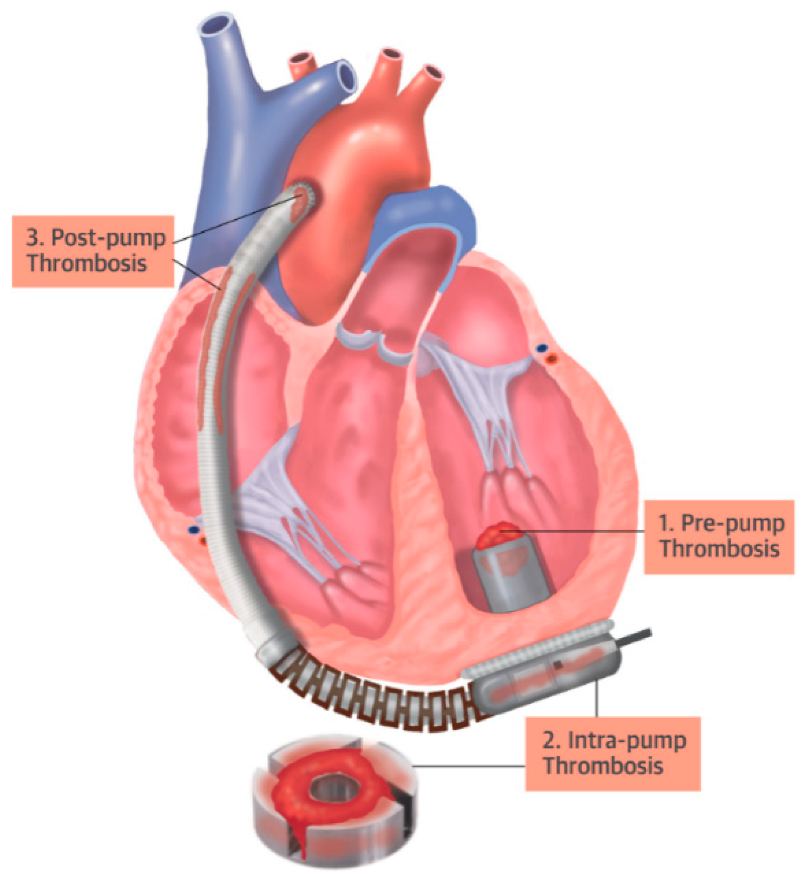
Thrombosis within the pump can compromise blood flow in three ways: (i) through thrombosis at the pump’s inlet cannula (pre-pump); (ii) through thrombosis at the pump rotor (intra-pump); or (iii) through thrombosis at two points on the pump outlet (post-pump): at the outlet cannula or the anastomosis stenosis.
Figure 5 presents a schematic of a heart with an implanted VAD and highlights the points of thrombosis adherence.
4.2. Risk Identification Study
It is standard practice in HAZOP to assemble a team of experts for the risk identification process within a facility or during specific processes [
34]. However, this was unnecessary in the present case, as the application example relies on secondary data from the analysis of the medical algorithm used to detect and treat blood flow obstructions in VADs [
15].
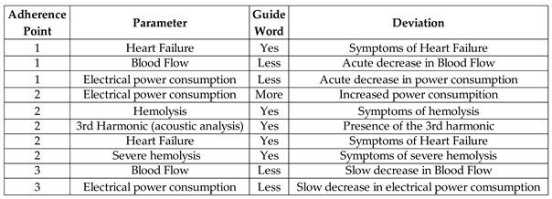
Table 2 consolidates information on the evaluated parameters, including the definition of guide words and deviations, with consideration given to the measurement resources. The information provided is based on the thrombosis adherence points in the device, as previously illustrated in
Figure 3.
An Adverse Activity was designated for each thrombosis adherence point in the device, facilitating the study of the undesirable events that arise from thrombosis adherence in three distinct regions, leading to the conception of an Adverse Process (AE1).
Table 3 presents information on Adverse Process AE1, the associated Adverse Activities AE1.1, AE1.2, and AE1.3, along with their respective causes.
Once the complete description of the parameters evaluated in Adverse Process AE1 was established, the risks involving the occurrence of pre-pump thrombosis were identified, and the recommended actions for each undesirable state were specified.
Table 4 presents the risk identification results and the Medical Team's recommended actions for the Adverse Activity 'Pre-pump Thrombosis (AE1.1)'.
Table 5 presents the results of risk identification and the survey of recommended actions by the Medical Team for the Adverse Activity 'Intra-pump Thrombosis (AE1.2)'.
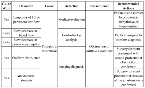
Table 6 presents the risk identification results and the Medical Team's recommended actions for the Adverse Activity ‘Post-pump Thrombosis (AE1.3)’.
Medical evaluation is required for a conclusive diagnosis of all three Adverse Activities. The evaluated parameters are derived from indirect detection and are used in identifying deviations, among which the following are highlighted:
The following steps outline the modeling of the Adverse Process AE1, aimed at defining the diagnostic model for thrombosis in the device and the monitoring model for the corresponding mitigation activities involving the three scenarios previously presented.
4.3. Systematic Approach for OSCVAD Modeling
The following sections provide guidelines for modeling the Adverse Process 'Thrombosis in the Device (AE1).'
Section 4.3.1 presents the development of the Adverse Process model 'Thrombosis in the Device (AE1)' to be encapsulated in an Adverse Event Diagnostic Module for the composition of the DMAD.
Section 4.3.2 presents the development of the Adverse Process Mitigation Module AE1 for the composition of the DMAPM.
4.3.1. Adverse Process Modeling
Each PFS was transcribed into an interpreted PN based on the process modeling resources presented
2. A legend in each PN references the elements used: discrete transition, discrete place, oriented arc, and enabling arc. The enabling arcs are used to represent data flow with the external environment, and a table of inputs (transitions) and outputs (places) for the PN was included in Appendix A to facilitate understanding.
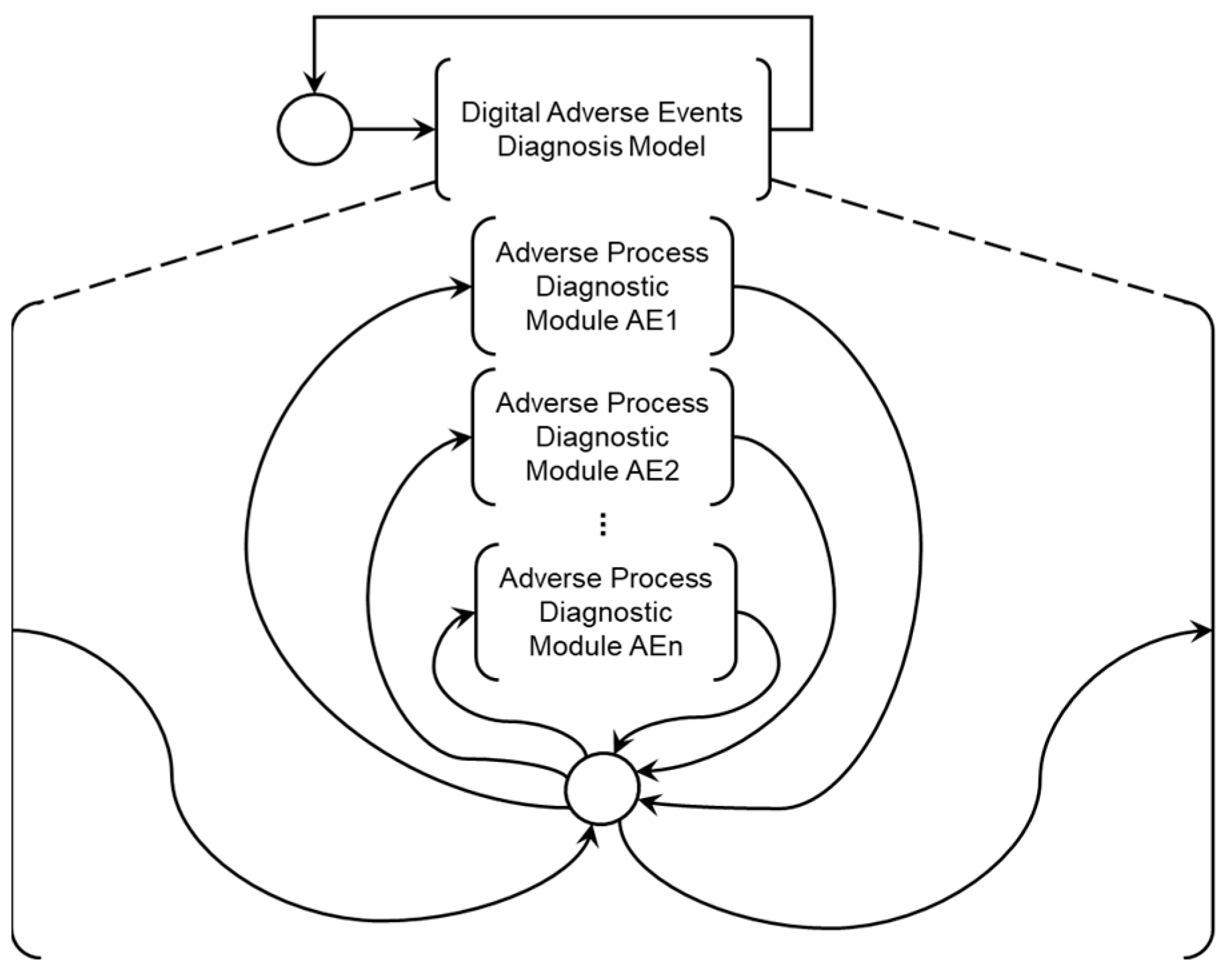
Figure 6 presents the Digital Adverse Event Diagnosis Model (DMAD), which supports the specification of diagnostic modules for Adverse Processes associated with known Adverse Events. The 'Adverse Process Diagnosis Module AE1' presented in
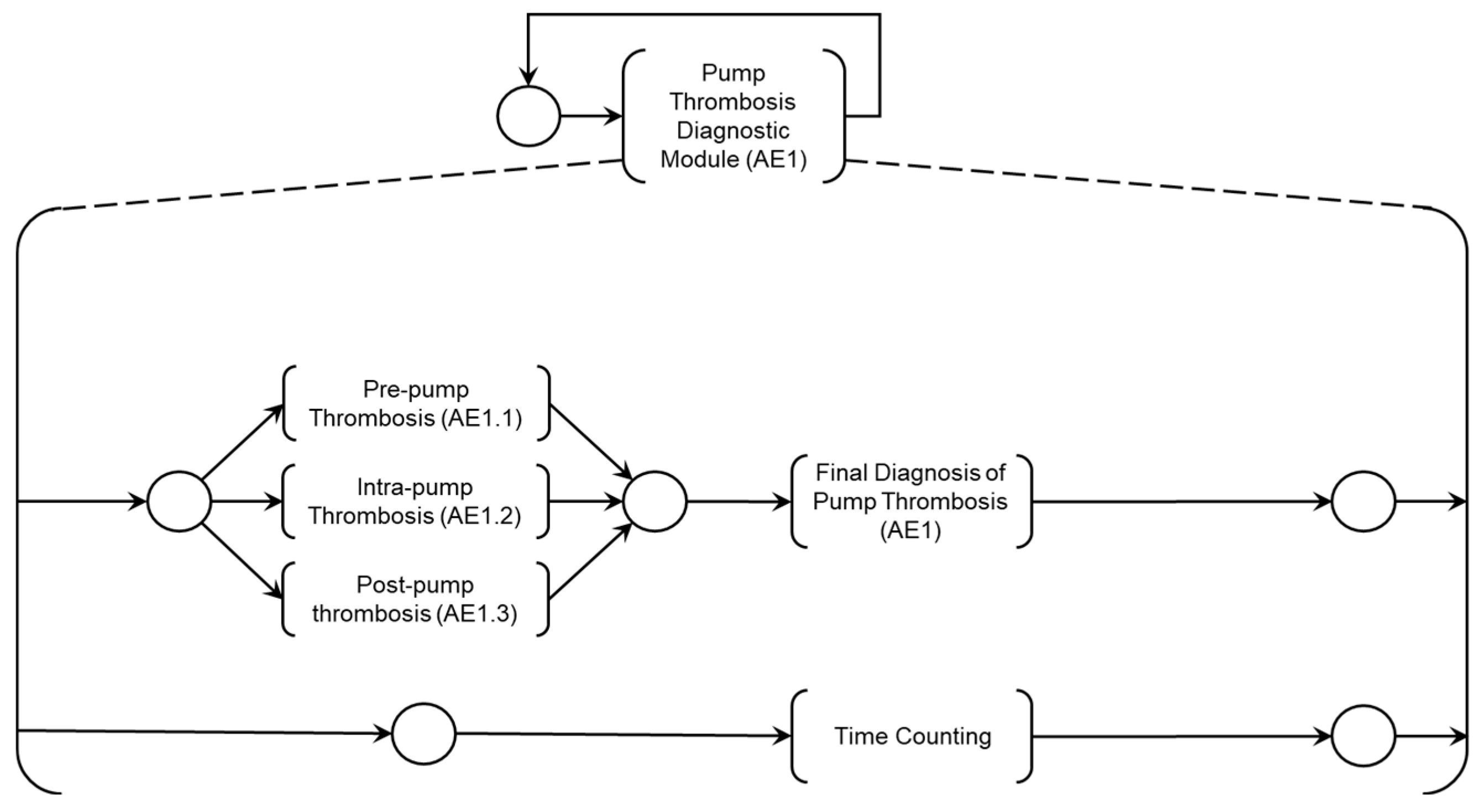
Figure 7 was developed through the HAZOP study for risk identification detailed in
Section 4.2 and was further elaborated into three Adverse Activities:
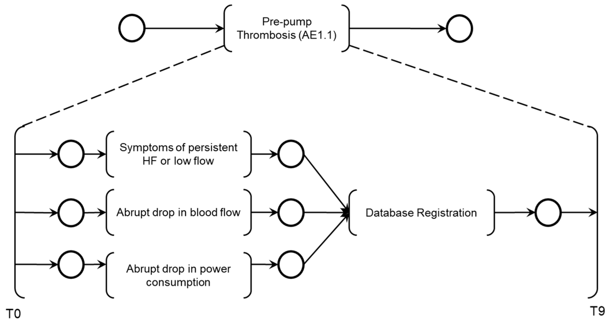
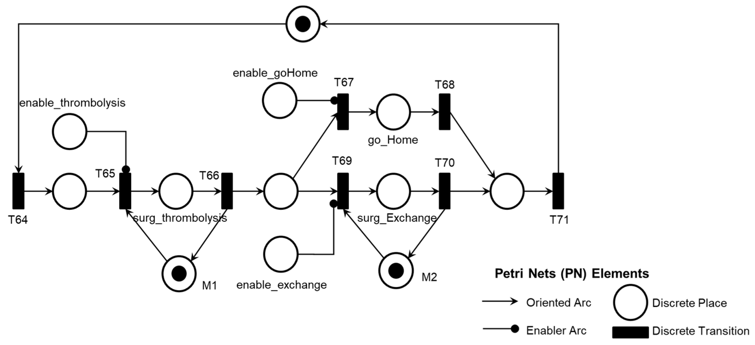
The PFS model 'Pre-pump Thrombosis AE1.1' is presented in
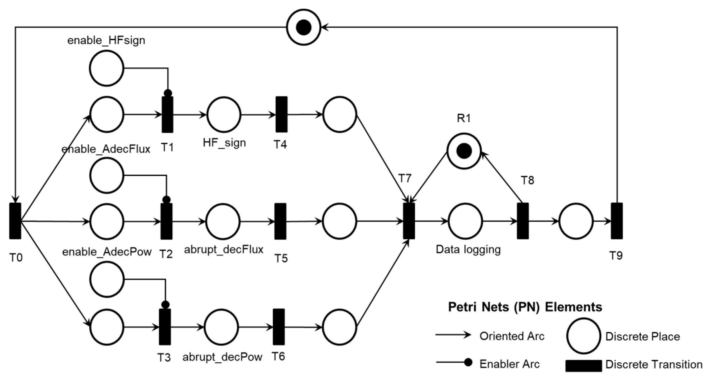
Figure 8, with the corresponding PN in
Figure 9.
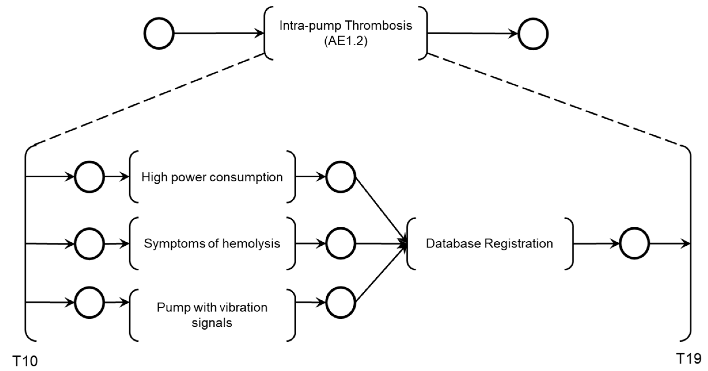
The PFS model 'Intra-pump Thrombosis AE1.2' is presented in
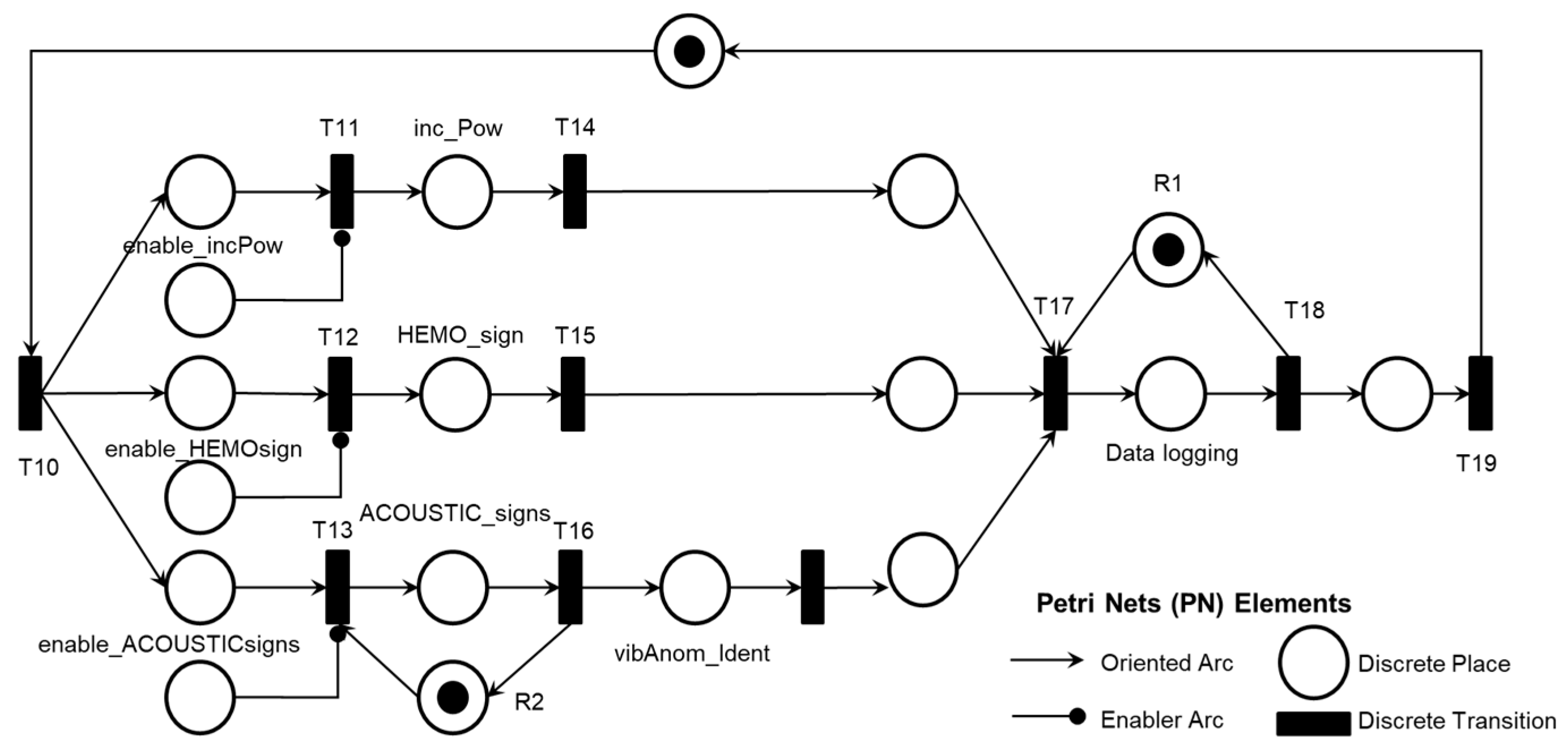
Figure 10, with the corresponding PN in
Figure 11.
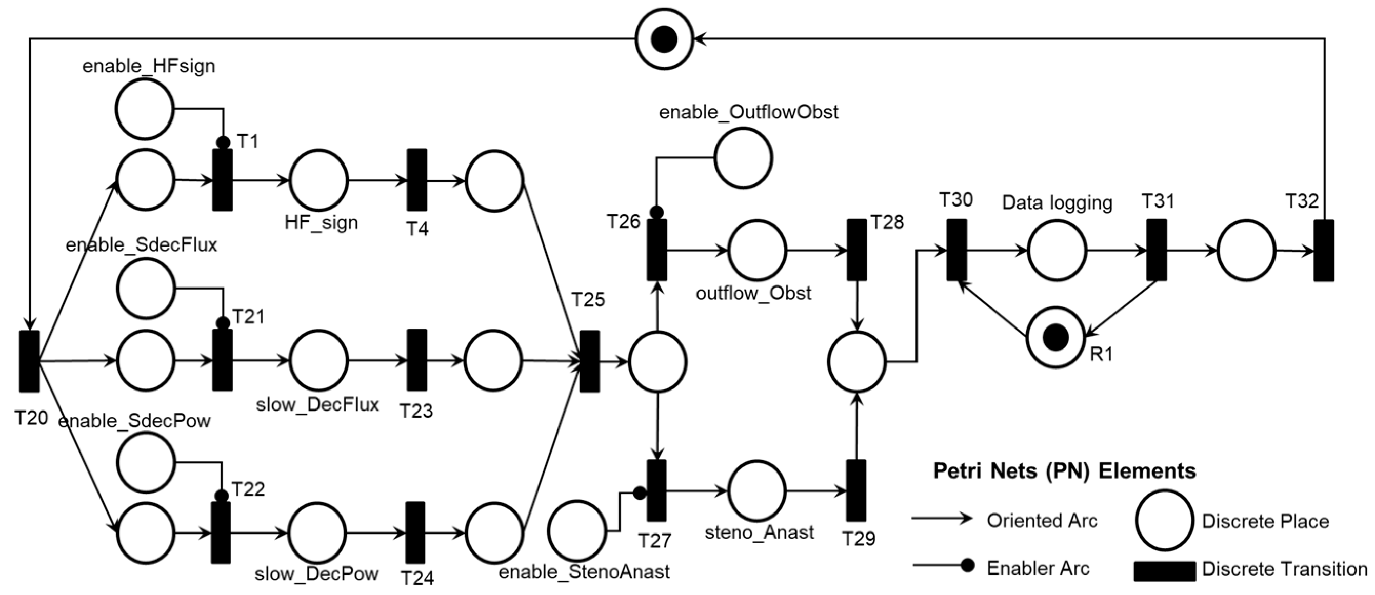
The PFS model 'Post-pump Thrombosis AE1.3' is presented in
Figure 12, with the corresponding PN in
Figure 13.
The mutually exclusive execution of activities AE1.1, AE1.2, or AE1.3 triggers the ‘Final diagnosis of Pump thrombosis (AE1)’ and the termination of the Adverse Process AE1 is determined by the timing executed by the ‘Time Counting’ activity.
As illustrated in
Figure 8, the simultaneous execution of the activities ‘Symptoms of HF or persistent low flow,’ ‘Abrupt drop in blood flow,’ and ‘Abrupt drop in power consumption’ enables the identification of pre-pump thrombosis and records this information through the execution of the ‘Database Registration’ activity.
Figure 9 illustrates the introduction of control elements and resources for sharing and representing data flow with the external environment.
As illustrated in
Figure 10, the simultaneous execution of the activities ‘High power consumption,’ ‘Symptoms of hemolysis,’ and ‘Pump with vibration signals’ enables the identification of intra-pump thrombosis and records the information through the execution of the ‘Database Registration’ activity.
Figure 11 illustrates the introduction of control elements and resources for sharing and representing data flow with the external environment.
As illustrated in
Figure 12, the simultaneous execution of the activities ‘Symptoms of HF or persistent low flow,’ ‘Slow decrease in blood flow,’ and ‘Slow decrease in power consumption’ enables the diagnosis of thrombosis location (anastomosis stenosis or obstruction at the outflow cannula) through the execution of the ‘Echocardiographic Diagnosis’ activity and subsequently records the post-pump thrombosis through the execution of the ‘Database Registration’ activity.
Figure 13 illustrates the introduction of control elements and resources for sharing and representing data flow with the external environment.
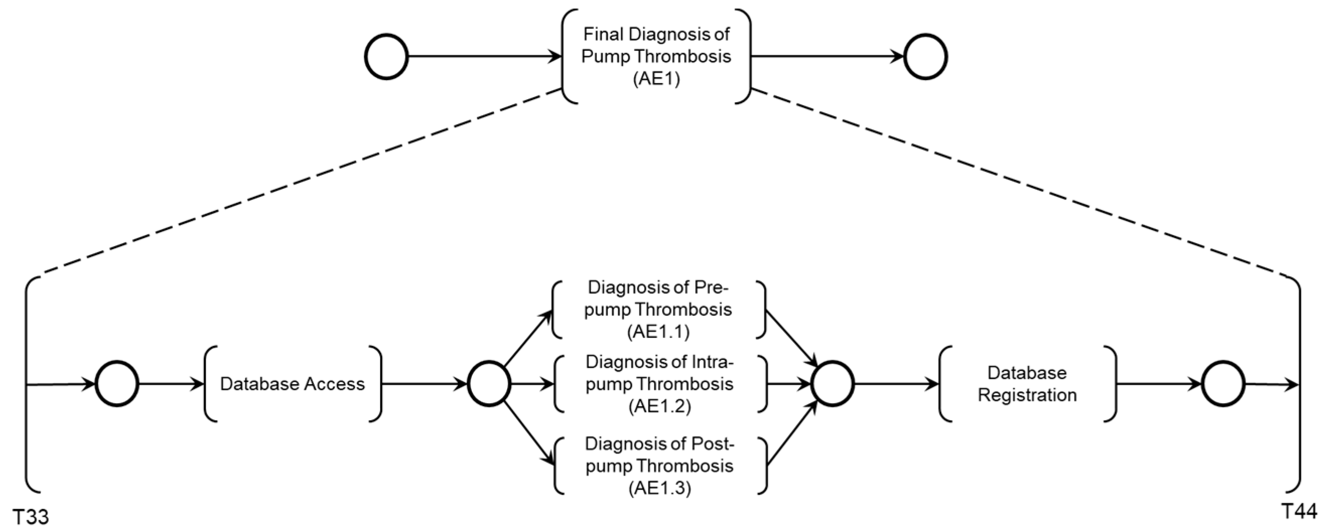
Finally, the diagnosis is carried out according to the logic described in the PFS model presented in
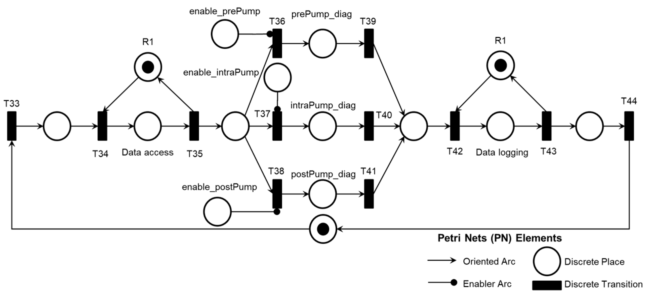
Figure 14, considering the Adverse Activities ‘Pre-pump Thrombosis AE1.1’, ‘Intra-pump Thrombosis AE1.2’, or ‘Post-pump Thrombosis AE1.3’ detailed in the PN as illustrated in
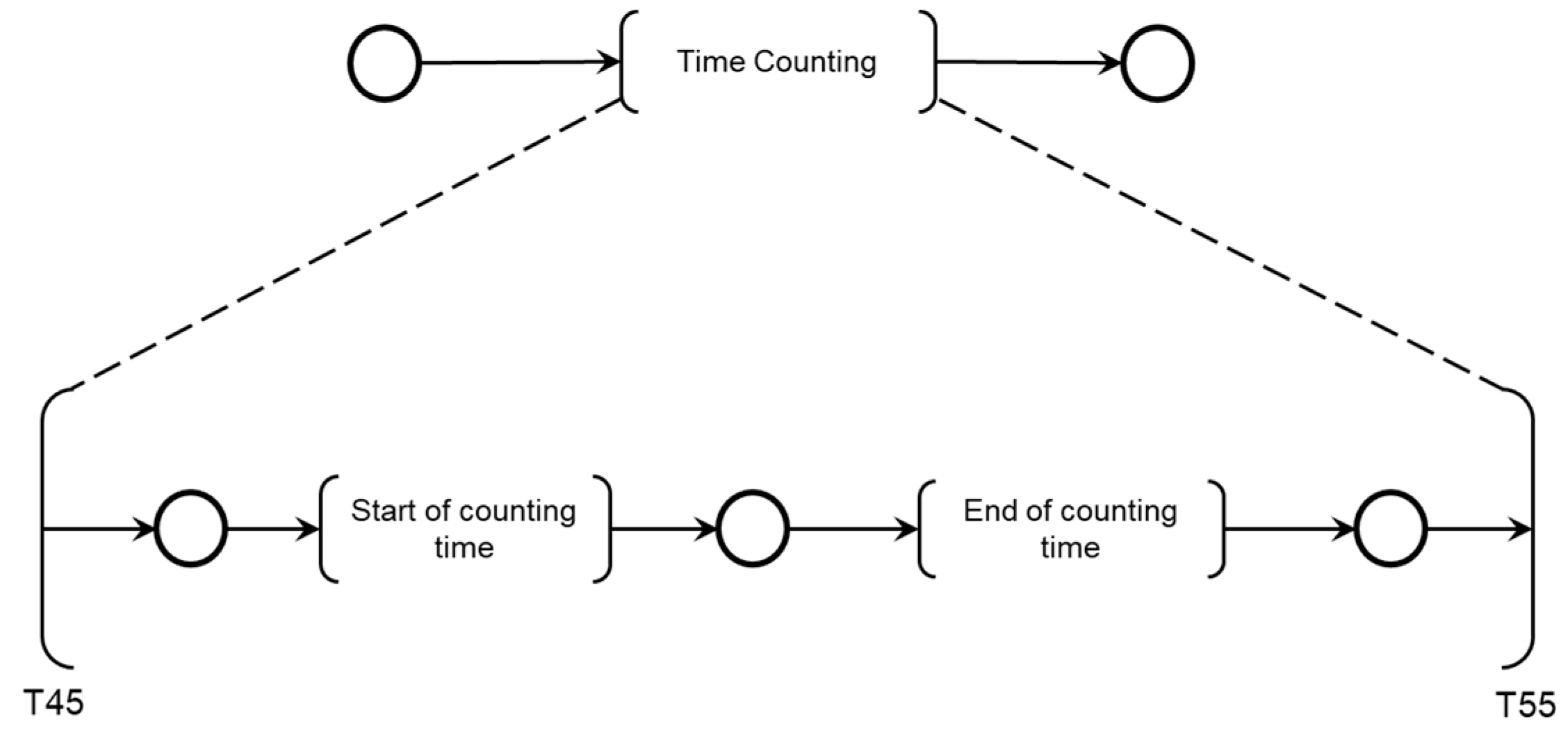
Figure 15. The conclusion of the Adverse Process AE1 is triggered by the execution of the activity ‘Final Diagnosis of Pump Thrombosis (AE1)’ concurrently with the execution of the ‘Time Count’ activity presented in
Figure 16.
As illustrated in
Figure 14, following the execution of the ‘Database Access’ activity, information is collected to diagnose one of the Adverse Activities AE1.1, AE1.2, or AE1.3. Subsequently, the diagnosis of the Adverse Process AE1 is finalized and registered.
Figure 15 illustrates the introduction of control elements and resources for sharing and representing data flow with the external environment.
As shown in
Figure 16, two sequential activities were specified for monitoring the maximum allowable time for patient care: ‘Start of counting time’ and ‘End of Counting Time.’
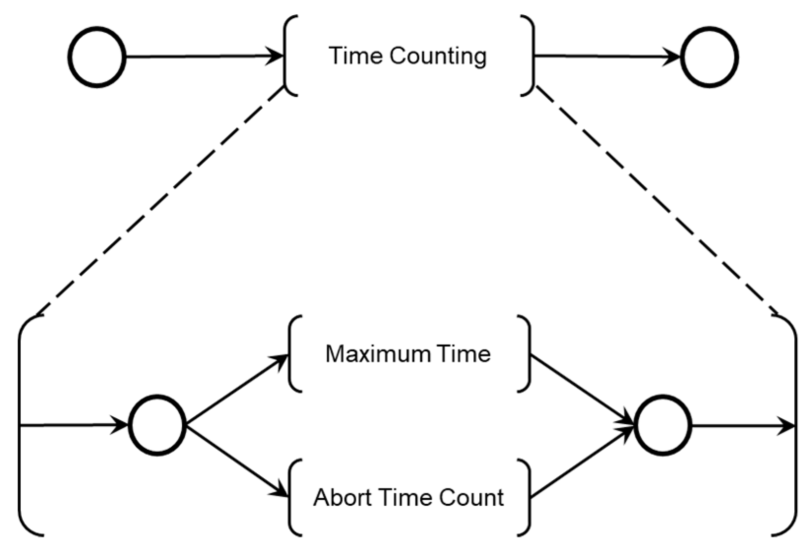
The maximum patient care time is monitored using a countdown timer with watchdog logic. The Medical Team also interacts with the diagnostic modules, allowing the time count to be aborted by medical decisions if the Adverse Process deteriorates before the maximum allowed time is reached. The model in PFS for the ‘End of Time Count’ activity is shown in
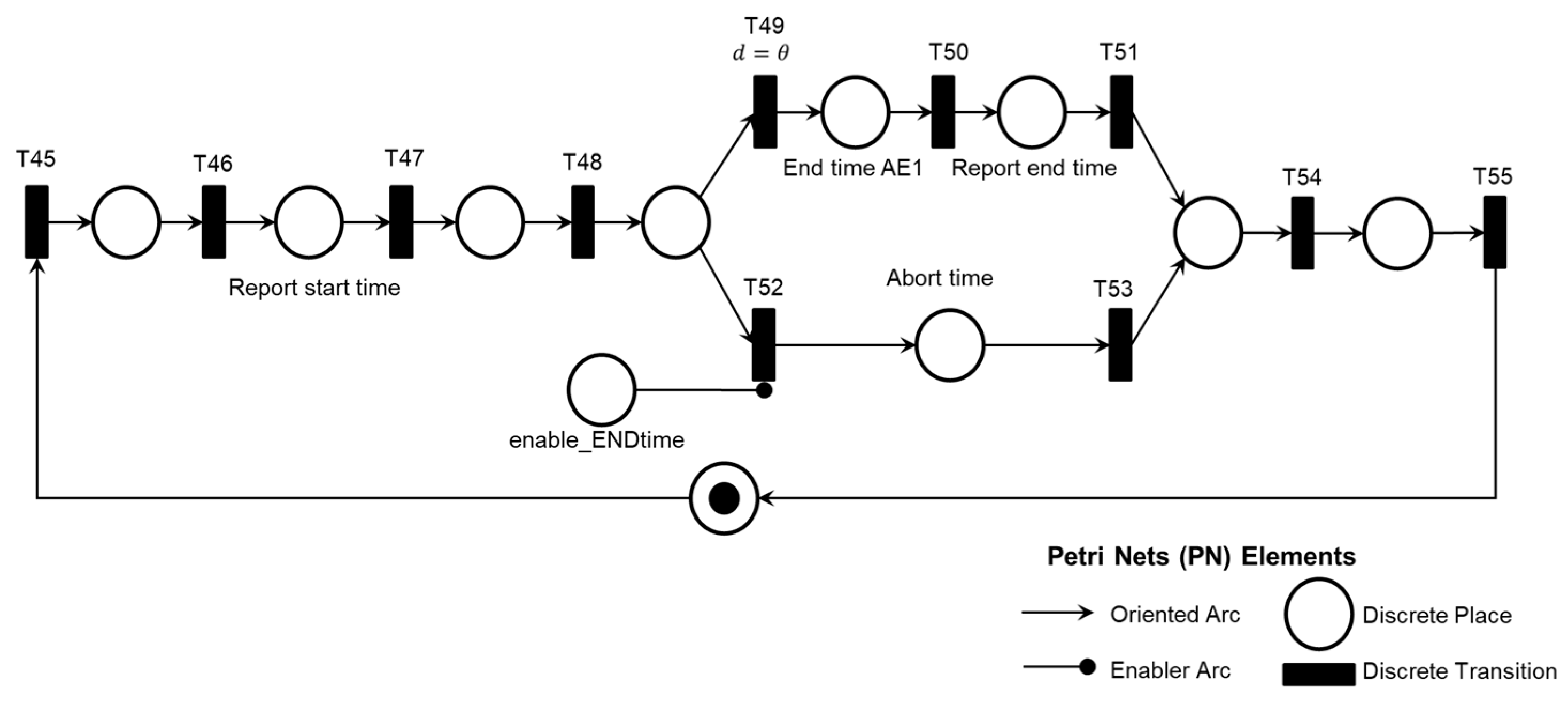
Figure 17, and the corresponding PN is shown in
Figure 18.
As illustrated in
Figure 17, two mutually exclusive activities determine the end of the time count: ‘Maximum Time,’ triggered by a countdown timer, and ‘Abort Time Count,’ which can be triggered at any time by the Medical Team’s command.
Figure 18 shows the introduction of control elements and resources for sharing and representing data flow with the external environment. Transition T49 is timed and functions as the watchdog for the adverse process.
4.3.2. Modeling of Intervention Protocols
Based on the previously presented diagnostic models, mitigation modules for Adverse Processes are specified, configuring Intervention Protocols defined by the Medical Team for the composition of the Digital Model for Adverse Process Monitoring (DMAPM) shown in
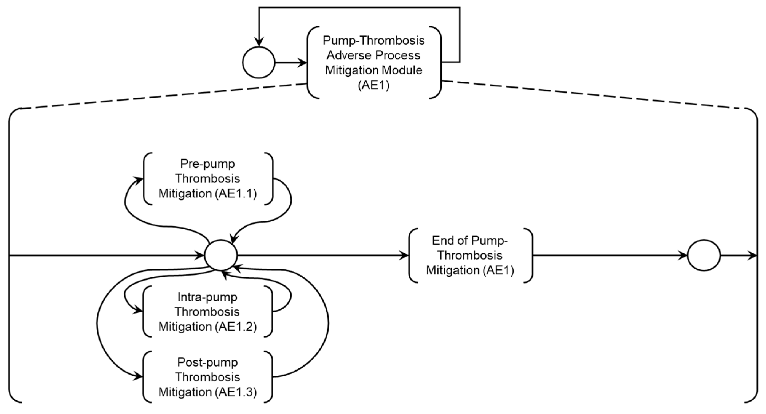
Figure 19. To address the patient’s needs regarding Adverse Process AE1, the ‘Adverse Process Mitigation Module (AE1)’ has been specified, as detailed in the PFS in
Figure 20. The Medical Team specifies mitigation activities which will be detailed below.
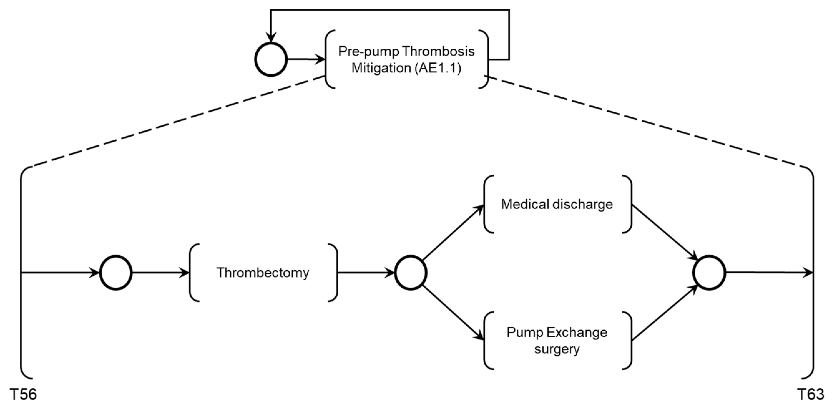
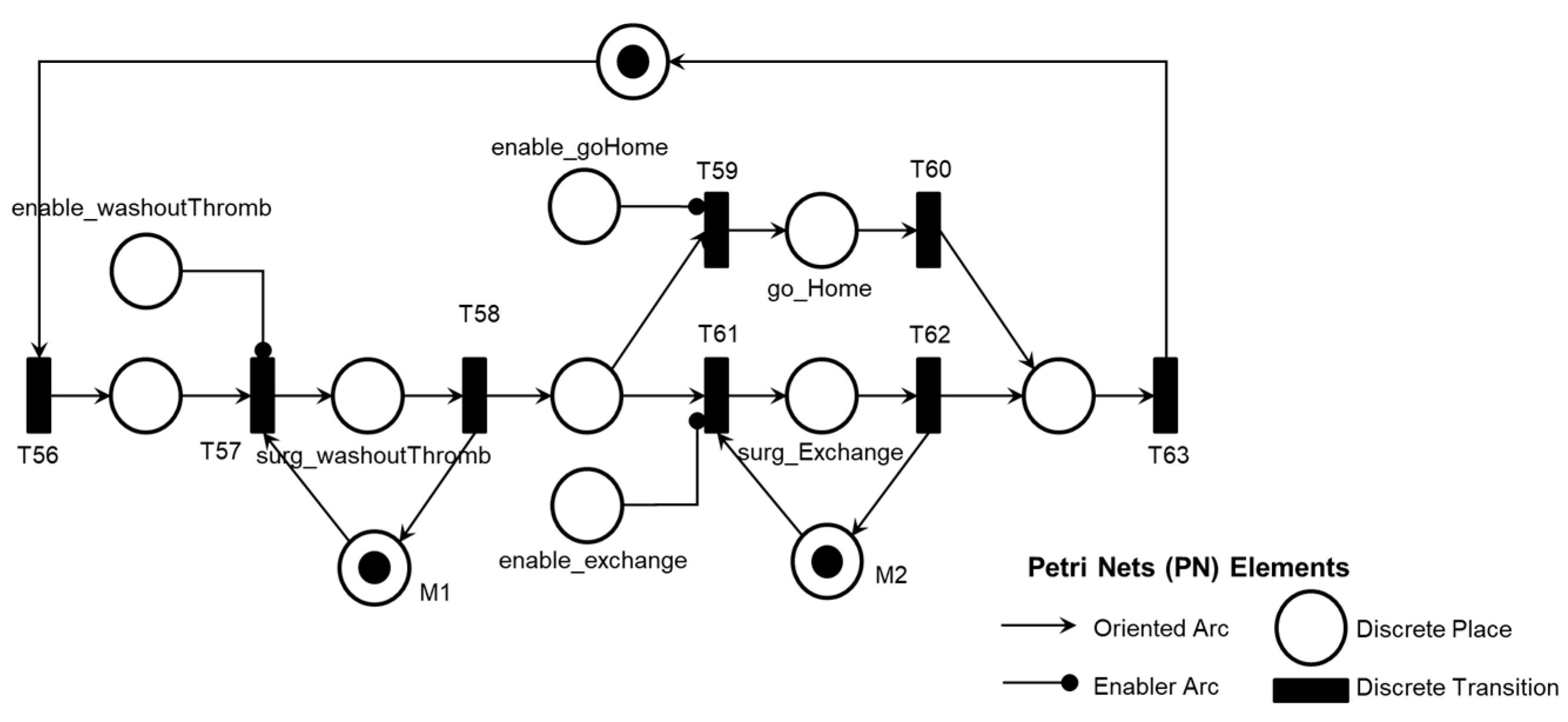
The activity ‘Pre-pump Thrombosis Mitigation AE1.1’ is detailed in the PFS in
Figure 21. When activated, the first mitigation activity that may be performed is ‘Thrombectomy’ followed by patient supervision by the Medical Team, based on monitoring the execution of required mitigation activities. Based on the recommended actions from the risk identification phase, activities that may be executed for the degeneration of Adverse Process AE1 include ‘Medical Discharge’ or ‘Pump Exchange Surgery.’
Figure 22 illustrates the corresponding PN for the activity ‘Pre-pump Thrombosis Mitigation AE1.1,’ including control elements and resources for data flow sharing and representation with the external environment.
As illustrated in
Figure 20, the activities ‘Pre-pump Thrombosis Mitigation AE1.1,’ ‘Intra-pump Thrombosis Mitigation AE1.2,’ and ‘Post-pump Thrombosis Mitigation AE1.3’ are linked to the Adverse Process (AE1), which is subdivided into these Adverse Activities.
As shown in
Figure 21, after executing the mitigation activity ‘Thrombectomy,’ two secondary mitigation activities may be enabled: ‘Medical Discharge,’ if thrombosis is successfully removed, or ‘Pump Exchange Surgery,’ if thrombosis persists.
Figure 22 illustrates the introduction of control elements and resources for sharing and representing data flow with the external environment.
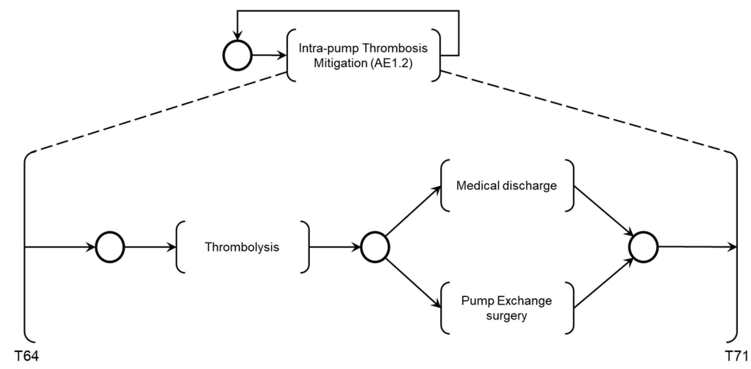
The activity ‘Intra-pump Thrombosis Mitigation AE1.2’ is detailed in PFS in
Figure 23. When enabled, the first mitigation activity that may be performed is ‘Thrombolysis,’ which degrades the adhered thrombus through clinical intervention. As mentioned, real-time information is provided for the Medical Team to monitor the execution of required mitigation activities. Based on the recommended actions from the risk identification phase, the activities that may be performed for the degeneration of Adverse Process AE1 include ‘Medical Discharge’ or ‘Pump Exchange Surgery.’
Figure 24 illustrates the corresponding PN for the activity ‘Intra-pump Thrombosis Mitigation AE1.2,’ which includes control elements and resources for data flow sharing and representation with the external environment.
As shown in
Figure 23, after executing the mitigation activity ‘Thrombolysis,’ two secondary mitigation activities may be enabled: ‘Medical Discharge’ if the thrombus is successfully degraded or ‘Pump Exchange Surgery’ if the thrombus persists.
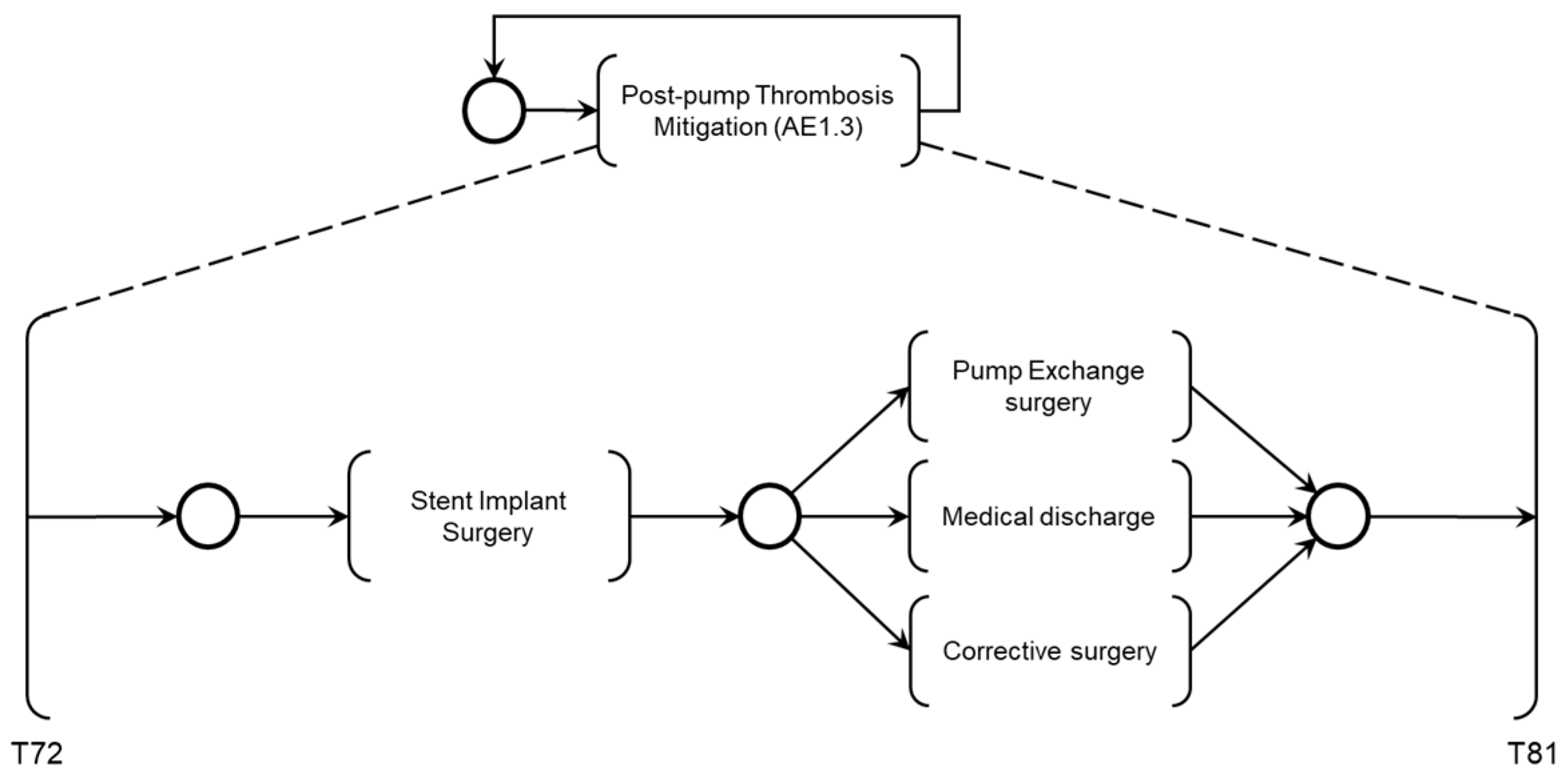
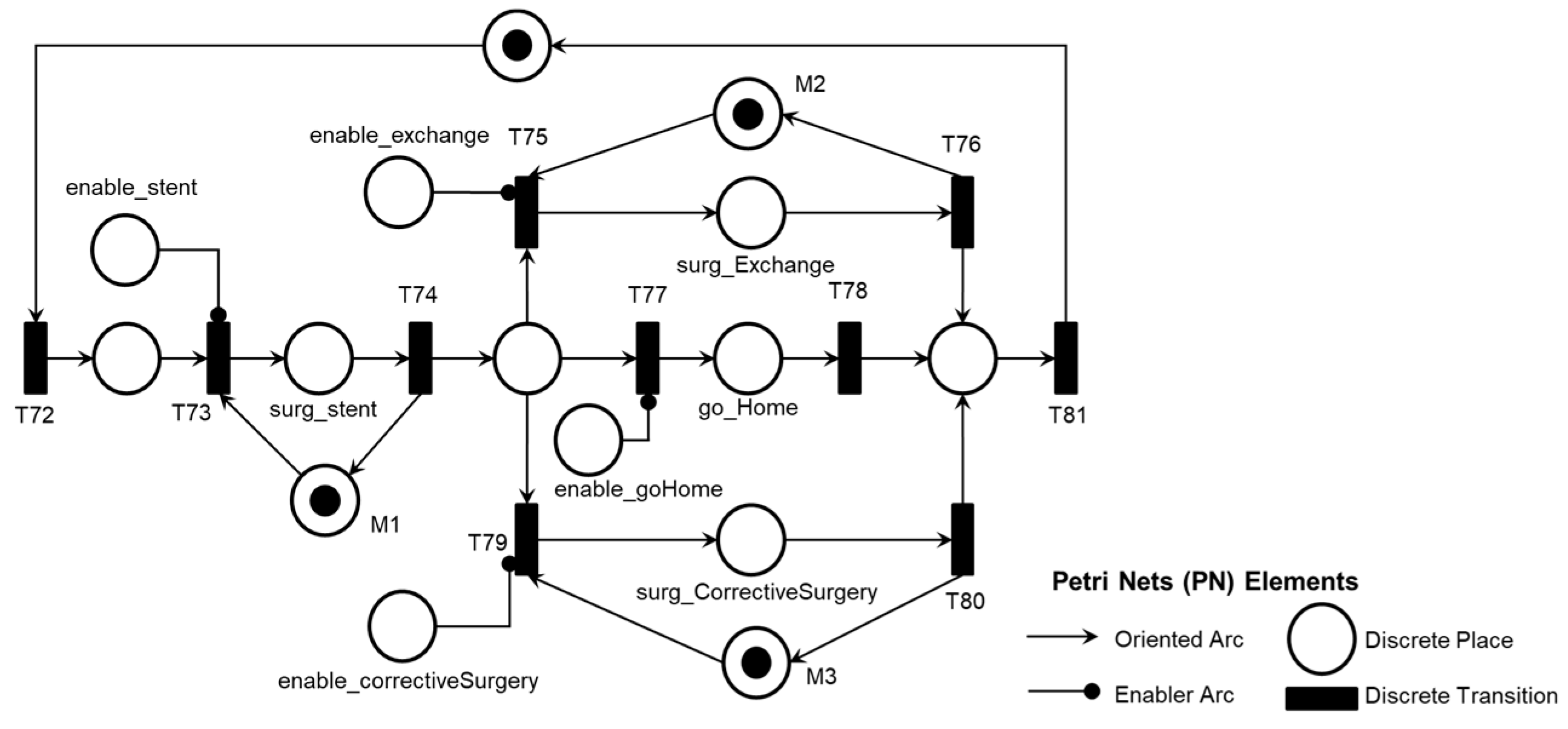
Figure 24 illustrates the introduction of the control elements and resources for sharing and representing data flow with the external environment. Similarly to the previous activities, the ‘Post-pump Thrombosis Mitigation AE1.3’ activity is detailed in PFS in
Figure 25. When enabled, the first mitigation activity that may be performed is ‘Stent Implant Surgery’ to restore adequate blood flow to the patient. As mentioned earlier, real-time information is provided to allow the Medical Team to monitor the execution of the required mitigation activities. The activities that may be executed for the degeneration of Adverse Process AE1, based on the recommended actions from the risk identification phase, include ‘Medical Discharge,’ ‘Pump Exchange Surgery,’ or ‘Cannula Position Correction Surgery,’ in the order defined by the supervising Medical Team.
Figure 26 illustrates the corresponding PN for the activity ‘Post-pump Thrombosis Mitigation AE1.3,’ mentioning control elements and resources for data flow sharing and representation with the external environment.
As illustrated in
Figure 25, after executing the mitigation activity ‘Stent Implant Surgery,’ three secondary mitigation activities may be enabled: ‘Pump Exchange Surgery’ if thrombosis persists, ‘Medical Discharge’ if adequate blood flow is restored, or ‘Corrective Surgery’ if repositioning of the outflow cannula is necessary.
Figure 26 illustrates the introduction of the control elements and resources for sharing and representing data flow with the external environment. The termination of the Adverse Process mitigation is enabled by the Medical Team’s decision based on the execution of mitigation activities within the established time frame for Adverse Process AE1, as illustrated in the PFS in
Figure 27 and detailed in the PN in
Figure 28. Thus, the models are timed, and the Medical Team is informed to monitor the maximum time needed for the degeneration of the Adverse Process through the DMAD. The DMAPM communicates with the DMAD to allow the Medical Team to monitor and perform necessary mitigation activities to restore the patient’s health state through the DMAPM.
As illustrated in
Figure 28, the introduction of the control elements and resources for sharing and representing data flow with the external environment.
5. Discussion
The work presents results based on an example of an EA to illustrate the method and demonstrates the steps for risk identification using HAZOP. However, IEC 31010 mentions 31 techniques that can be adopted, each with particularities and contributions. Therefore, risk scenario evaluation and its consequences can be obtained through a combination of techniques [
37]. As previously mentioned, ISO 14971 guides specifying techniques for medical device regulation, particularly for VADs [
36]. Therefore, a risk identification study can be conducted for each EA using techniques that meet each EA's specific objectives and inherent characteristics. The development of studies involving other EAs can complement the DMAD and DMAPM outlined in the event-oriented structure model of the OSCVAD, which facilitates horizontal and vertical integration between OSCVAD entities and enables continuous updates to its monitoring and supervision algorithms for Adverse Processes.
Another principal factor to highlight is the involvement of a team of specialists. Although it has not compromised the results achieved in this work, this aspect can be improved, as the contribution of the Medical Team is fundamental and indispensable for conducting a risk identification study. Therefore, to propose a risk management plan [
37] involving other EAs, a team of specialists should be assembled, as required by HAZOP [
35], to conduct a robust study incorporating medical knowledge related to clinical protocols for patient care and management during the lifecycle of an implanted VAD.
The medical algorithm for detecting and treating blood flow obstruction in VADs [
15] was used as secondary data for implementing HAZOP and provides valuable information that contributes to the standardization of diagnostic and treatment processes for flow obstruction caused by thrombosis in the pump. It was essential to develop diagnostic models for AEs and Intervention Protocols based on the knowledge of the Medical Team. The method provides the necessary rigor for constructing isomorphic models based on the knowledge obtained during the risk identification phase. Therefore, it ensures that the transition of unwanted states and the activation of Intervention Protocols are executed according to the patient's needs. All models in PN were validated using the PIPE2 tool [
38].
Regarding unwanted state transitions, the model represents the system's behavior in response to a specific EA and provides the Medical Team with real-time information to monitor the dynamic evolution of the OSCVAD. In other words, the models are timed and start the time count according to the identification of deviations inherent to the EA in question, allowing the Medical Team to monitor the time count and enable the necessary mitigation activities in real-time to address the patient’s needs with appropriate priority.
Concerning the Intervention Protocols, the Medical Team enables the specification and command of mitigation actions according to the patient’s needs. Therefore, using the event-oriented structure of the OSCVAD allows for dynamic monitoring of the executed mitigation activities and those that can still be performed within the required time for the patient.
6. Conclusion
With the application of the proposed method, it was possible to obtain timed models that allow for the supervision of the dynamic behavior of Adverse Processes initiated by the occurrence of AEs. The digitization of the Adverse Process promptly enables communication between the Medical Team and other entities, improving care for patients with implanted VADs.
In this context, a modular, event-oriented structure was established, allowing the Medical Team to monitor the dynamic evolution of unwanted states and supervise patient care processes, initiating interventions as needed.
The system's entities were organized to support horizontal and vertical integration. These are fundamental characteristics for implementing a system geared towards the Health 4.0 context, where collaborative interaction occurs between the VAD, the patient, and the supervising Medical Team.
With the presented results, new diagnostic and mitigation modules can be specified for the progression of the new Adverse Process. These are essential for health regeneration and significantly contribute to reducing the risk of death for patients with implanted VADs.
Therefore, the OSCVAD features an adaptable structure that meets patient needs, which can continuously learn by managing new adverse processes identified in the community of patients with implanted VADs.
This work aims to contribute to the development of supervision systems that align with new technologies present in the Industry 4.0 context [
34] and to address the exclusive demands of an open system that fosters collaborative interaction among medical devices embedded in patients, the patients themselves, and Medical Teams, for the formulation of future intelligent systems geared towards Health 4.0 capable of meeting specific requirements for each patient.
Author Contributions
Conceptualization, J.R.C.S.S., M.A.O.P., and D.J.S.F.; data curation, J.R.C.S.S., M.A.O.P., and D.J.S.F.; formal analysis, J.R.C.S.S., M.A.O.P., and D.J.S.F.; investigation, J.R.C.S.S., M.A.O.P. and D.J.S.F.; methodology, J.R.C.S.S., M.A.O.P., and D.J.S.F.; project administration, J.R.C.S.S., M.A.O.P., and D.J.S.F.; resources, M.A.O.P., F.J., P.E.M., and D.J.S.F.; supervision, M.A.O.P., and D.J.S.F.; validation, J.R.C.S.S., M.A.O.P., and D.J.S.F.; visualization, J.R.C.S.S., M.A.O.P., F.J., P.E.M., and D.J.S.F.; writing—original draft preparation, J.R.C.S.S., M.A.O.P., and D.J.S.F.; writing—review and editing, J.R.C.S.S., M.A.O.P., and D.J.S.F.. All authors have read and agreed to the published version of the manuscript.
Institutional Review Board Statement
Not applicable.
Informed Consent Statement
Not applicable.
Data Availability Statement
The data supporting the conclusions of this study are available upon request by contacting the author via the email provided in the header.
Acknowledgments
The authors thank the Brazilian governmental agencies CNPq, CAPES, and the Sao Paulo Research Foundation (FAPESP) - grant nº 2013/ 24434-0.
Conflicts of Interest
The authors declare no conflict of interest.
Abbreviations
The following abbreviations are used in this manuscript:
AE - Adverse Event
AHA - American Heart Association
BTR - Bridge to recovery
BTT - Bridge to Transplant
CS - Critical System
DES - Discrete-event system
DMAD - Digital Model for Adverse Event Diagnosis
DMAPM - Digital Model for Adverse Process Monitoring
DT - Destination Therapy
FDA - Food Drug Administration
HAZOP - Hazard and Operability Studies
HF - Heart Failure
HM2 - HeartMate 2
HM3 - HeartMate 3
MDR - Medical Device Report
OSCVAD - Open System for Supervising Critical Adverse Processes in Patients with Implanted Ventricular Assist Devices
PFS - Production Flow Schema
PN - Petri Nets
VAD - Ventricular Assist Device
| 1 |
Adverse Process is a set of undesirable states that follow the occurrence of an Adverse Event. In the Adverse Process, each triggered transition results in a change in the dynamic behavior of the OSCVAD, with effects that can be harmful to the patient, involving situations that increase the risk of death. |
| 2 |
Interpreted Petri Nets allow for the description of complex data structure models and enable the addition of communication mechanisms through input signals and system outputs, making it possible to represent and analyze systems that interact with the external environment [ 29]. |
References
- Types of Heart Failure. Available online: https://www.heart.org/en/health-topics/heart-failure/what-is-heartfailure/types-of-heart-failure (accessed on 20 May 2024).
- Peura, J.L.; Colvin-Adams, M. Recommendations for the Use of Mechanical Circulatory Support: Device Strategies and Patient Selection. Circulation 2012, 126, 2648–2667. [Google Scholar] [CrossRef] [PubMed]
- Teuteberg, J.J.; Cleveland, J.C. The Society of Thoracic Surgeons Intermacs 2019 Annual Report: The Changing Landscape of Devices and Indications. Annals of Thoracic Surgery 2020, 109, 649–660. [Google Scholar] [CrossRef] [PubMed]
- Lundteigen, M.A.; Rausand, M. Architectural constraints in IEC 61508: Do they have the intended effect? Reliability Engineering & System Safety 2009, 94, 520–525. [Google Scholar]
- Jorde, U.P.; Saeed, O. The Society of Thoracic Surgeons Intermacs 2023 Annual Report: Focus on Magnetically Levitated Devices. The Annals of Thoracic Surgery 2024, 117, 33–44. [Google Scholar] [CrossRef]
- HeartWare HVAD System Instructions for Use. Available online: https://manuals.medtronic.com/manuals/ (accessed on 6 May 2024).
- HeartMate 3 Left Ventricu lar Assist System Patient Handbook. Available online: https://manuals.eifu.abbott/en/detail-screen.html (accessed on 21 May 2024).
- HeartMate II Left Ventricular Assist System (LVAS) Patient Handbook. Available online: https://manuals.eifu.abbott/en/detail-screen.html (accessed on 21 May 2024).
- André, C.M.; Diolino, J.S. Safety control architecture for ventricular assist devices. Machines 2021, 10, p. [Google Scholar]
- Mcilvennan, C.K.; Magid, K.H. Clinical outcomes after continuous-flow left ventricular assist device A systematic review. Circulation: Heart Failure 2014, 7, 1003–1013. [Google Scholar] [PubMed]
- Mehra, M.R.; Uriel, N. A Fully Magnetically Levitated Left Ventricular Assist Device — Final Report. New England Journal of Medicine 2019, 380, 1618–1627. [Google Scholar] [CrossRef]
- Anderson, O.; Davis, R. Surgical adverse events: a systematic review. The American Journal of Surgery 2013, 206, 253–262. [Google Scholar] [CrossRef]
- What is a Serious Adverse Event? Available online: https://www.fda.gov/safety/reporting-serious-problems-fda/what-serious-adverseevent (accessed on 23 May 2024).
- Chen, C.; Du, J. Management of incessant ventricular arrhythmias in a patient with left ventricular assist device: a case report. Journal of Cardiothoracic Surgery 2024, 19, 1–6. [Google Scholar] [CrossRef]
- Scandroglio, A.M.; Kaufmann, F. Diagnosis and Treatment Algorithm for Blood Flow Obstructions in Patients With Left Ventricular Assist Device. Journal of the American College of Cardiology 2016, 67, 2758–2768. [Google Scholar] [CrossRef]
- Ucar, M.; Karakas, M.S. Early thrombus formation in a patient with HeartWare left ventricular assist device presenting with acute heart failure. Journal of the Saudi Heart Association 2016, 28, 49–51. [Google Scholar] [CrossRef] [PubMed]
- Uriel, N.; Han, J. Device thrombosis in HeartMate II continuous-flow left ventricular assist devices: A multifactorial phenomenon. Journal of Heart and Lung Transplantation 2014, 33, 51–59. [Google Scholar] [CrossRef] [PubMed]
- Jasinski, R.; Tesch, K. Innovative Implantable Left Ventricular Assist Device—Performance under Various Resistances and Operating Frequency Conditions. Applied Sciences 2023, 13, 7785. [Google Scholar] [CrossRef]
- Molina, E.J.; Shah, P. The Society of Thoracic Surgeons Intermacs 2020 Annual Report. The Annals of Thoracic Surgery 2021, 111, 778–792. [Google Scholar] [CrossRef]
- Medical Device Recalls. Home Medical Devices Medical Device Safety. Available online: https://www.fda.gov/medical-devices/medical-devicerecalls/what-medical-device-recall (accessed on 23 May 2024).
- Medical Device Databases. Available online: https://www.fda.gov/medicaldevices/device-advice-comprehensive-regulatory-assistance/medical-devicedatabases (accessed on 2 July 2024).
- TPLC - Total Product Life Cycle. Available online: https://www.accessdata.fda.gov/scripts/cdrh/cfdocs/cfTPLC/tplc.cfm?id=DSQ&min_report_year=2024 (accessed on 23 May 2024).
- Fountoulaki, K.; Ventoulis, I. Emergency department risk assessment and disposition of acute heart failure patients: existing evidence and ongoing challenges. Heart Failure Reviews 2022, 28, 781–793. [Google Scholar] [CrossRef]
- Lee, D.S.; Lee, J.S. Prospective Validation of the Emergency Heart Failure Mortality Risk Grade for Acute Heart Failure. Circulation 2019, 139, 1146–1156. [Google Scholar] [CrossRef] [PubMed]
- Siddiqi, T.J.; Usman, M.S. Utility of the CHA2DS2-VASc score for predicting ischaemic stroke in patients with or without atrial fibrillation: a systematic review and meta-analysis. European Journal of Preventive Cardiology 2022, 29, 625–631. [Google Scholar] [CrossRef] [PubMed]
- Zhu, W.; He, W. The HAS-BLED Score for Predicting Major Bleeding Risk in Anticoagulated Patients With Atrial Fibrillation: A Systematic Review and Meta-analysis. Clinical Cardiology 2015, 38, 555–561. [Google Scholar] [CrossRef] [PubMed]
- Estrada, E. What is a Complex System, After All? Found Sci 2023, 1, 1–28. [Google Scholar] [CrossRef]
- Ladyman, J.; Lambert, J. What is a complex system? European Journal for Philosophy of Science 2013, 3, 33–67. [Google Scholar] [CrossRef]
- Cardoso, J.; Valette, R. Redes de petri, 1st ed.; UFSC: Florianópolis-SC, Brasil, 1997; pp. 30–39. [Google Scholar]
- Cassandras, C.; Lafortune, S. Introduction to discrete event systems, 2nd ed.; Springer: Boston, MA, USA, 2008; p. 71. [Google Scholar]
- Murata, T. Petri nets: Properties, analysis and applications. Proceedings of the IEEE 1989, 77, 541–580. [Google Scholar] [CrossRef]
- Grobelna, I. ; Szcześniak, Interpreted Petri Nets Applied to Autonomous Components within Electric Power Systems. Applied Sciences 2022, 12, 4772. [Google Scholar] [CrossRef]
- Reisig, W. A Primer in Petri Net Design. Springerverlag 1992, 1, 120. [Google Scholar]
- Pisching, M.A.; Pessoa, M.A.; Junqueira, F. PFS/PN technique to model Industry 4.0 systems based on RAMI 4.0. In: 2018 IEEE 23rd International Conference on Emerging Technologies and Factory Automation (ETFA), Turin, Italia, (4, 09, 2018).
- IEC 61882: Hazard and operability studies (HAZOP studies) - Application guide. Geneva, Switzerland, 2016.
- ISO 14971: Medical devices — Application of risk management to medical devices. Geneva, Switzerland, 2019.
- IEC 31010: Risk management — Risk assessment techniques. Geneva, Switzerland, 2019.
- Plattform Independent Petri Net Editor 2. Available online: https://pipe2.sourceforge.net (accessed on 13 August 2024).
- Barboza, M.; Sousa, J.R. Supervisory and Intelligent Systems. In Bioengineering and Biomaterials in Ventricular Assist Devices, 1st ed.; Bock, E.G., Ed.; CRC Press: New York, USA, 2021; Volume 1, pp. 111–132. [Google Scholar]
- Santos, B.; Barboza, M. Intelligent embedded system for physiological control of ventricular assist devices in health 4.0 Background. International Journal of Advances in Medical Biotechnology 2023, 5, 8–21. [Google Scholar] [CrossRef]
Figure 1.
Essential elements of a PFS graph. The square brackets represent the 'activity' element, the circle represents the 'distributor' element, and the arrow represents the 'arc' element.
Figure 1.
Essential elements of a PFS graph. The square brackets represent the 'activity' element, the circle represents the 'distributor' element, and the arrow represents the 'arc' element.
Figure 2.
Conversion of the model from PFS to PN through successive top-down refinement. In (A), an activity in PFS; in (B), another possible representation of the same activity element; in (C), a combined PFS/PN representation (the activity is represented by a discrete place between two discrete transitions); and in (D), the corresponding PN is represented.
Figure 3.
Event-oriented structure model of the OSCVAD for digitizing patient care processes.
Figure 3.
Event-oriented structure model of the OSCVAD for digitizing patient care processes.
Figure 4.
The model for structuring OSCVAD processes is represented.
Figure 4.
The model for structuring OSCVAD processes is represented.
Figure 5.
The thrombosis adherence points associated with the use of the VAD are presented. (1) adherence at the blood pump’s inlet cannula (pre-pump), (2) adherence at the blood pump’s rotor (intra-pump), and (3) adherence at the pump’s outlet at two points (post-pump) [
15].
Figure 5.
The thrombosis adherence points associated with the use of the VAD are presented. (1) adherence at the blood pump’s inlet cannula (pre-pump), (2) adherence at the blood pump’s rotor (intra-pump), and (3) adherence at the pump’s outlet at two points (post-pump) [
15].
Figure 6.
PFS and detailing of the Digital Model for Adverse Event Diagnosis (DMAD).
Figure 6.
PFS and detailing of the Digital Model for Adverse Event Diagnosis (DMAD).
Figure 7.
PFS and detailing of the diagnostic module for thrombosis in the device (AE1).
Figure 7.
PFS and detailing of the diagnostic module for thrombosis in the device (AE1).
Figure 8.
PFS and detailing of the Adverse Activity ‘Pre-pump Thrombosis AE1.1’.
Figure 8.
PFS and detailing of the Adverse Activity ‘Pre-pump Thrombosis AE1.1’.
Figure 9.
PN corresponding to the Adverse Activity ‘Pre-pump Thrombosis AE1.1’.
Figure 9.
PN corresponding to the Adverse Activity ‘Pre-pump Thrombosis AE1.1’.
Figure 10.
PFS and detailing of the Adverse Activity ‘Intra-pump Thrombosis AE1.2’.
Figure 10.
PFS and detailing of the Adverse Activity ‘Intra-pump Thrombosis AE1.2’.
Figure 11.
PN corresponding to the Adverse Activity ‘Intra-pump Thrombosis AE1.2’.
Figure 11.
PN corresponding to the Adverse Activity ‘Intra-pump Thrombosis AE1.2’.
Figure 12.
PFS and detailing of the Adverse Activity ‘Post-pump Thrombosis AE1.3’.
Figure 12.
PFS and detailing of the Adverse Activity ‘Post-pump Thrombosis AE1.3’.
Figure 13.
PN corresponding to the Adverse Activity ‘Post-pump Thrombosis AE1.3’.
Figure 13.
PN corresponding to the Adverse Activity ‘Post-pump Thrombosis AE1.3’.
Figure 14.
PFS and detailing of the activity ‘Final Diagnosis of Pump Thrombosis (AE1)’.
Figure 14.
PFS and detailing of the activity ‘Final Diagnosis of Pump Thrombosis (AE1)’.
Figure 15.
PN corresponds to the ‘Final Diagnosis of Pump Thrombosis (AE1)’ activity.
Figure 15.
PN corresponds to the ‘Final Diagnosis of Pump Thrombosis (AE1)’ activity.
Figure 16.
PFS and detailing of the activity ‘Time Counting’.
Figure 16.
PFS and detailing of the activity ‘Time Counting’.
Figure 17.
PFS and detailing of the activity ‘End of Counting Time.’
Figure 17.
PFS and detailing of the activity ‘End of Counting Time.’
Figure 18.
Corresponding PN for the ‘Time Counting’ activity.
Figure 18.
Corresponding PN for the ‘Time Counting’ activity.
Figure 19.
PFS and detailing of the Digital Model for Adverse Process Monitoring (DMAPM).
Figure 19.
PFS and detailing of the Digital Model for Adverse Process Monitoring (DMAPM).
Figure 20.
PFS and detailing of the thrombosis mitigation module for the device (AE1).
Figure 20.
PFS and detailing of the thrombosis mitigation module for the device (AE1).
Figure 21.
PFS and detailing of the activity ‘Pre-pump Thrombosis Mitigation AE1.1’.
Figure 21.
PFS and detailing of the activity ‘Pre-pump Thrombosis Mitigation AE1.1’.
Figure 22.
PN corresponding to the activity ‘Pre-pump Thrombosis Mitigation AE1.1’.
Figure 22.
PN corresponding to the activity ‘Pre-pump Thrombosis Mitigation AE1.1’.
Figure 23.
PFS and detailing of the activity ‘Intra-pump Thrombosis Mitigation AE1.2’.
Figure 23.
PFS and detailing of the activity ‘Intra-pump Thrombosis Mitigation AE1.2’.
Figure 24.
PN is corresponding to the activity ‘Intra-pump Thrombosis Mitigation AE1.2’.
Figure 24.
PN is corresponding to the activity ‘Intra-pump Thrombosis Mitigation AE1.2’.
Figure 25.
PFS and detailing of the activity ‘Post-pump Thrombosis Mitigation AE1.3’.
Figure 25.
PFS and detailing of the activity ‘Post-pump Thrombosis Mitigation AE1.3’.
Figure 26.
PN is corresponding to the activity ‘Post-pump Thrombosis Mitigation AE1.3’.
Figure 26.
PN is corresponding to the activity ‘Post-pump Thrombosis Mitigation AE1.3’.
Figure 27.
PFS of the activity ‘End of Pump-Thrombosis Mitigation (AE1)’.
Figure 27.
PFS of the activity ‘End of Pump-Thrombosis Mitigation (AE1)’.
Figure 28.
PN corresponds to the ‘End of Pump-Thrombosis Mitigation (AE1)’ activity.
Figure 28.
PN corresponds to the ‘End of Pump-Thrombosis Mitigation (AE1)’ activity.
Table 1.
MDRs have been submitted to the FDA to report AEs over the past four years.
Table 1.
MDRs have been submitted to the FDA to report AEs over the past four years.
Table 2.
Thrombosis Adherence Points, Parameters, Guide Words, and HAZOP Deviations.
Table 2.
Thrombosis Adherence Points, Parameters, Guide Words, and HAZOP Deviations.
Table 3.
Adverse Process, Adverse Activities, and Causes.
Table 3.
Adverse Process, Adverse Activities, and Causes.
Table 4.
HAZOP Table for Pre-pump Thrombosis (AE1.1).
Table 4.
HAZOP Table for Pre-pump Thrombosis (AE1.1).
Table 5.
HAZOP Table for Intra-pump Thrombosis (AE1.2).
Table 5.
HAZOP Table for Intra-pump Thrombosis (AE1.2).
Table 6.
HAZOP Table for Post-pump Thrombosis (AE1.3).
Table 6.
HAZOP Table for Post-pump Thrombosis (AE1.3).
|
Disclaimer/Publisher’s Note: The statements, opinions and data contained in all publications are solely those of the individual author(s) and contributor(s) and not of MDPI and/or the editor(s). MDPI and/or the editor(s) disclaim responsibility for any injury to people or property resulting from any ideas, methods, instructions or products referred to in the content. |
© 2024 by the authors. Licensee MDPI, Basel, Switzerland. This article is an open access article distributed under the terms and conditions of the Creative Commons Attribution (CC BY) license (http://creativecommons.org/licenses/by/4.0/).

