1. Introduction
Magnetic nanoparticles (MNPs) are materials with dimensions in the nanometre range, typically between 1 and 100 nanometres. At this scale, unique magnetic properties emerge, distinguishing them from their bulk counterparts. MNPs represent a special class of nanoparticles (NPs) that can interact with an external magnetic field as a direct consequence of their superparamagnetic, ferrimagnetic, and/or ferromagnetic properties [
1]. The MNPs in the past decade have gained great attention because of their promising results in various fields [
2]. Magnetic nanoparticles (MNPs) have become a crucial tool in the biomedical area, transforming different diagnostic and therapeutic methods significantly. Due to their distinctive magnetic properties, as well as their compatibility with biological systems and capacity to be modified on the surface, these materials are highly suitable for a wide range of applications, including magnetic resonance imaging (MRI) [
3], targeted drug administration [
4], and cancer therapy [
5]. The potential of MNPs in biomedical applications is extensive, and the current research is investigating novel and effective methods to employ these NPs. The prospects involve the advancement of multifunctional MNPs, with the ability to perform both diagnosis and treatment simultaneously, known commonly as ‘theragnostic’ [
6,
7,
8]. MNPs have a significant benefit in their large surface area-to-volume ratio, enabling various functionalisation and alterations that respond to specific biomedical requirements. The ability to adapt allows for the creation of magnetic nanoparticles (MNPs) with tailored characteristics [
9]. The MNPs-based sensors have shown remarkable application in different fields, including food technology, lab-testing, clinical diagnosis, and environmental monitoring [
10]. MNPs-based biosensors have achieved tremendous status,due to distinct properties, such as magnetic signalling and magnetic separation [
11].
Despite the enormous potential of MNPs, these materials are not ideal with regard to being active elements in sensing applications, which is why they have been used most often as capture/preconcentration elements in a sensing system, as distinct from being the sensor itself. This is because the low electrical conductivity and limited optical properties compromises the ability of MNPs to be the transducing element of a sensor [
12]. Another challenge facing the use of MNPs in sensing is because of the MNPs having a large surface area to volume ratio and low surface charge at neutral pH, dispersions of these particles typically have low stability, with the MNPs tending to aggregate when dispersed in solvents [
13]. Such aggregation can be reduced with appropriate surface chemistry, which is also vital for sensing applications [
14]. However, the surfaces of most magnetic materials are not highly compatible with well-defined surface chemistry such as the alkanethiol system. Gold coating of the MNPs addresses all the above-mentioned challenges, including conductivity, optical properties [
15], biocompatibility [
16], bio affinity through functionalisation of the amine/thiol terminal groups [
17], and chemical stability by protecting the magnetic core from aggregation, oxidation and corrosion [
18].
Gold coated magnetic nanoparticles (MNPs-Au) have been recognised and applied in analytical chemistry, mostly for bio-separation and the development of electrochemical and optical sensors [
19]. Applications of MNPs-Au in biomedicine have also been explored, including magnetic resonance imaging contrast agents [
20], targeted drug delivery [
21] as well as downstream processing [
22]. The reason that MNPs-Au can be used for so many applications is because they are highly versatile; the optical and magnetic properties of the particles can be tuned and tailored to applications by changing their size, gold shell thickness, shape, charge and surface modification [
23].
More than two decades have passed since the first reports on the synthesis of MNPs-Au, but challenges remain in different aspects of working with this category of nanoparticle [
24]. The first challenge is how to prepare highly monodisperse iron or iron oxide nanocrystals efficiently. This requires the nanoparticles to be made with precise control of particle size and magnetic properties. The greater challenge is how to coat the core effectively with a smooth, complete and tunable gold shell. The most common methods are to coat magnetic nanoparticles by depositing gold directly onto the core surface, or by using a chelating material between the core and the gold shell [
23].
The properties of MNPs-Au make overcoming these challenges worthwhile, and the last few years have seen considerable progress in the synthesis and application of MNPs-Au. The first part of this article focuses on the synthesis of iron oxide nanocrystals using the coprecipitation method, followed by the formation of the gold shell using ultrasonic spray pyrolysis (USP). The optical, magnetic and zeta potential properties are discussed following this.
2. Materials and Methods
2.1. MNPs` Preparation with Coprecipitation
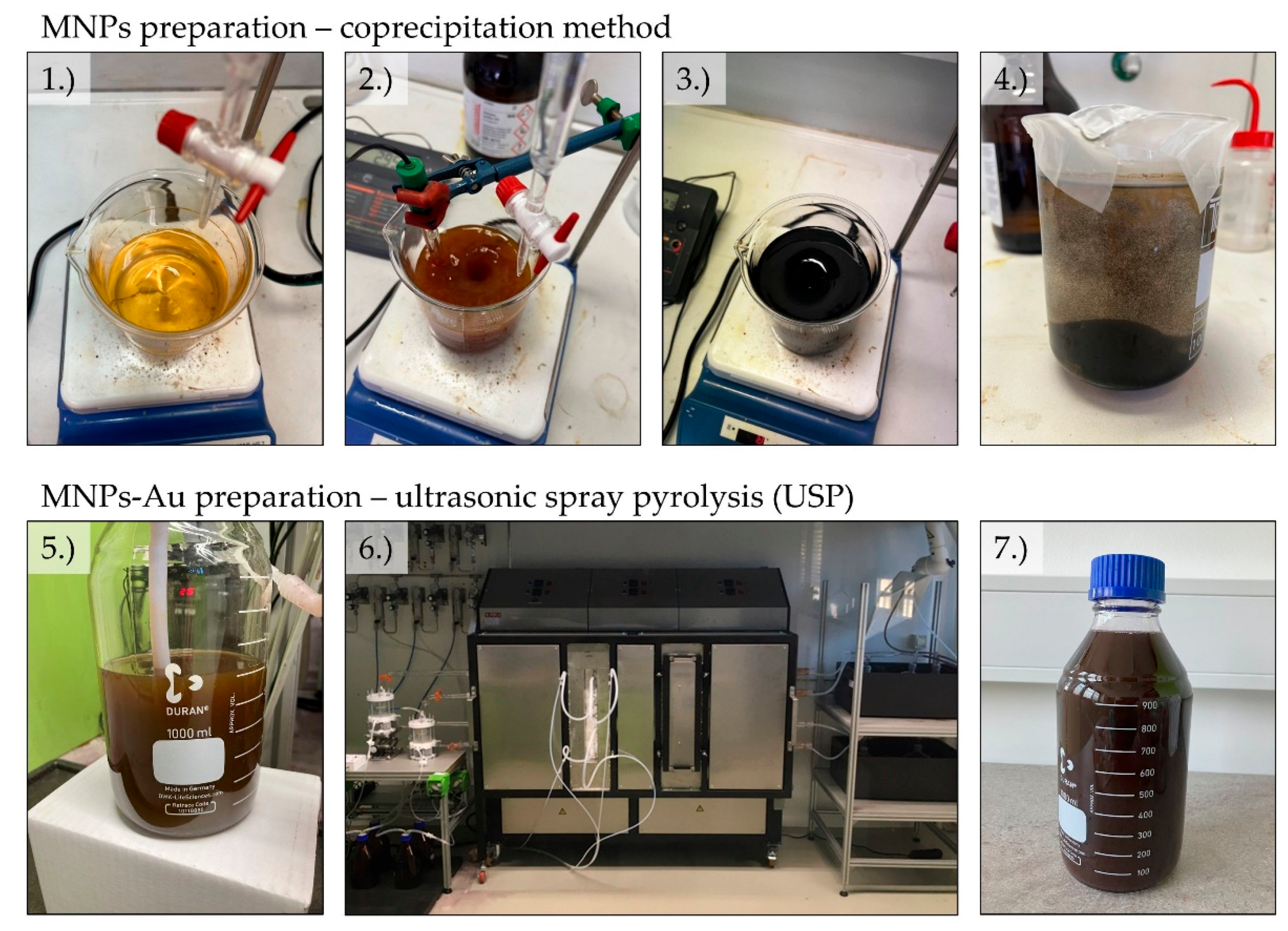
Magnetic nanoparticles were obtained using the coprecipitation method. 3,75 grams of iron (II) sulphate heptahydrate (Sigma-Aldrich) and 2,97 grams of iron (III) sulphate hydrate (Sigma-Aldrich) were weighed into a 1000 mL beaker. 500 mL of distilled water was added to the beaker and the sulphates were allowed to dissolve. A solution of ammonia in water was prepared - 3 mL of ammonia (Sigma-Aldrich) dissolved in 150 mL of distilled water. A pH meter was placed in a beaker. The ammonia solution was added dropwise to the beaker to raise the pH to 3. This pH was maintained for 30 minutes. Then, 250 mL of pure ammonia was added and left to stir for 30 minutes. A magnet was placed at the bottom of the beaker and the particles were allowed to settle. The remaining liquid was poured off, the magnet removed, and the nanoparticles rinsed with distilled water. This was repeated 5 times. After examining the nanoparticles using scanning electron microscopy, the decision was made to synthesize nanoparticles using lower concentrations of both iron sulphates. Thus, three other syntheses were made, using 1/2, 1/4 and 1/8 of the original mass of iron sulphates. We determined that the suspension made with 0,47 g of iron (II) sulphate heptahydrate and 0,37 g of iron (III) sulphate hydrate (1/8) is the most appropriate for further characterisation – the suspension appeared to have the least amount of aggregation of magnetic nanoparticles.
2.2. MNPs-Au Preparation with USP
Coating of the MNPs with gold (MNPs-Au) was achieved with ultrasonic spray pyrolysis (USP). USP uses an ultrasound membrane to produce micron-sized droplets of a selected dissolved precursor. These droplets are then transported into a tube furnace with a neutral gas, wherein the precursor droplets are dried and densified into solid particles at high temperatures. A reaction gas may also be introduced for facilitating the production of solid particles. For the experimental work, a proprietary USP device was used (Zlatarna Celje d.o.o., Celje, Slovenia), with an ultrasonic membrane with 1.65 MHz, a tube furnace with a quartz tube with a 1.5 m length and 35 mm internal diameter. The tube is separated into two heating zones with lengths of 0.5 and 1.0 m, for droplet evaporation and particle reaction, respectively. A reaction gas inlet is attached to the tube between these heating zones. The final particles are collected in 3 serially connected gas washing bottles, with a collection medium for stabilisation.
The precursor solutions for USP were prepared by adding the suspension of MNPs obtained by the coprecipitation method (80 mL, containing 390 mg of MNPs) to 700 mL of deionised (DI) water, and then adding 3,12 g of AuCl (≈ 50% Au basis) (Glentham Life Sciences Ltd, Corsham, United Kingdom). The concentrations of MNPs and Au in the precursor solutions were 0.5 and 2 g/l, respectively. The evaporation zone was set at 200 °C, while the reaction zone was set at 400 °C. The carrier gas used was N
2, with a flow rate of 4 l/min, and the reduction gas used was H
2 with a flow rate of 4 l/min. The synthesis was carried out for 2 hours. The gas washing bottles contained 1.0 L of a water solution with an added 4.5 g/L of Polyvinylpyrrolidone (PVP) MW 30,000 (Sigma-Aldrich, Darmstadt, Germany) for the stabilisation process.
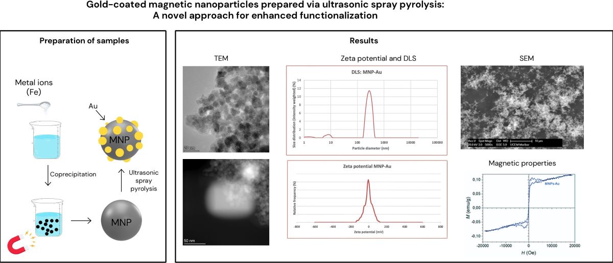
Figure 1 represents the preparation of our samples.
2.3. Optical Emission Spectrometry with Inductively Coupled Plasma (ICP-OES)
An ICP-OES analysis was used for determination of the MNPs in the prepared particle suspension for preparation of MNPs-Au with USP. The final MNPs-Au particle concentrations were also determined. An HP, Agilent 7500 CE spectrometer, equipped with a collision cell (Santa Clara, CA, USA), was used to determine the Fe and Au content in the suspensions, with a power of 1.5 kW, a Meinhard nebuliser, a plasma gas flow of 15 L/min, a nebuliser gas flow of 0.85 L/min, a make-up gas flow of 0.28 L/min and a reaction gas flow of 4.0 mL/min. The instrument was calibrated with matrix-matched calibration solutions, with a relative measurement uncertainty estimated as ± 3%.
2.4. Transmission Electron Microscopy (TEM) and Energy Dispersive X-ray Spectroscopy (EDS)
The MNP and MNP-Au samples were characterised using scanning/transmission electron microscopy (S/TEM). A Talos F200i (Thermo Fisher Scientific, USA) TEM/STEM, operated at 200 kV, was employed for imaging, with an integrated Selected Area Electron Diffraction (SAED) pattern analysis, and Energy Dispersive X-ray Spectroscopy (EDS) using a UK Bruker XFlash 6 | 30 EDS Detector and Velox Analytical Software. A drop of the prepared particle suspensions was deposited onto copper TEM grids coated with an amorphous carbon lacy film, followed by drying prior to the S/TEM examination.
2.5. Scanning Electron Microscopy (SEM) and EDS
A Sirion 400NC (FEI, Hillsboro, OR, USA) with an INCA 350 EDS (Oxford Instruments, Abingdon, Oxfordshire, UK) was used for the SEM/EDS analyses. A droplet of the samples was set on a SEM stub holder with graphite tape and left to dry in a desiccator. The dried sample was then coated with carbon for increased conductivity during the SEM imaging and EDS analysis.
2.6. Dynamic Light Scattering (DLS) and Zeta Potential
DLS analysis and zeta potential measurements were used on a suspension of magnetic nanoparticles and a suspension of magnetic nanoparticles coated with gold. The samples were moved into an omega cuvette and put into a DLS analysis machine. The analysis was conducted on a Malvern Zetasizer Nano ZS instrument (Malvern Panalytical, Worcestershire, UK).
2.7. Magnetic Measurement
Room temperature magnetic hysteresis loops of dried samples were measured with a vibrating-sample magnetometer VSM Lake Shore 7307 (Lake Shore Cryotronics, Westerville, OH, USA).
3. Results
3.1. TEM Analysis
The TEM images of MNPs and MNPs-Au were analysed to assess their morphology before and after USP.
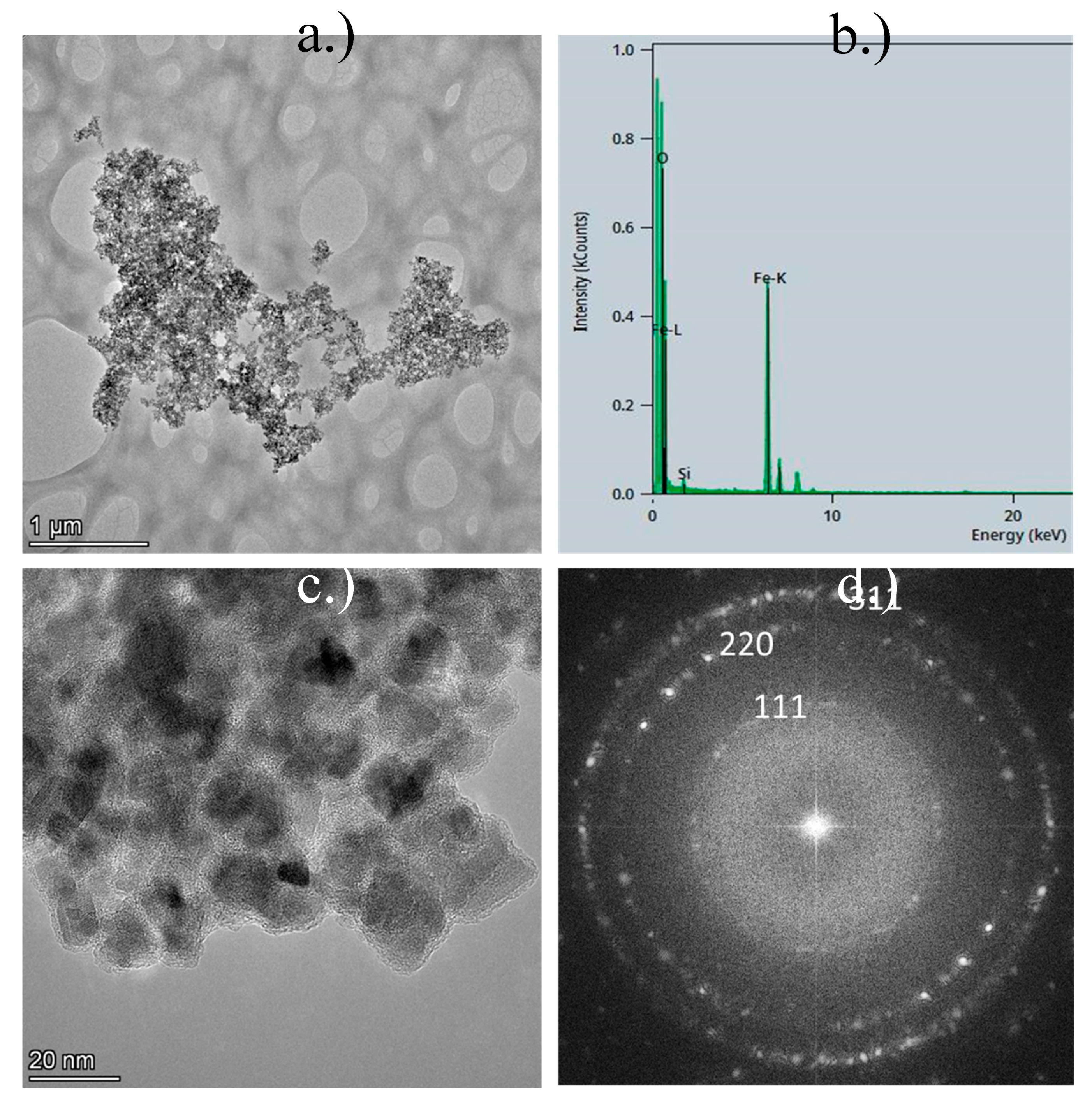
Figure 2 presents the TEM results for the MNPs. In
Figure 2 a.) and
Figure 2 c.), clusters of MNPs are observed, with some particles exhibiting spherical shapes, while others are irregular. The particle sizes range from 5 nm to 25 nm, although significant aggregation is evident. The EDS analysis (
Figure 2 b.)) revealed a prominent oxygen peak, alongside two Fe-L and Fe-K peaks, indicating a high iron content in the sample. A small silicon peak was also detected, likely due to contamination, or originating from the substrate material.
Figure 2 d.) displays a 2-D Fast Fourier Transform (FFT), characterised by a concentric ring diffraction pattern with some brighter, more distinct spots. This suggests the presence of larger crystallites, while the continuity of the rings indicates that the crystallites are small (in the nanometre range) and oriented randomly, signifying a nanocrystalline material. Each ring corresponds to a specific set of crystallographic planes within the nanoparticles. The ring pattern suggests that the nanoparticles are polycrystalline, composed of numerous small crystallites with varying orientations. The sharp, regularly spaced spots and rings suggest that the nanoparticles are highly crystalline, with well-defined atomic planes. The presence of rings, rather than single diffraction spots, indicates that the nanoparticles are not single crystals, but consist of multiple crystallites in random orientations. The electron diffraction pattern can be indexed to the Fe
3O
4 cubic phase of iron oxide, as illustrated in
Figure 2 d.).
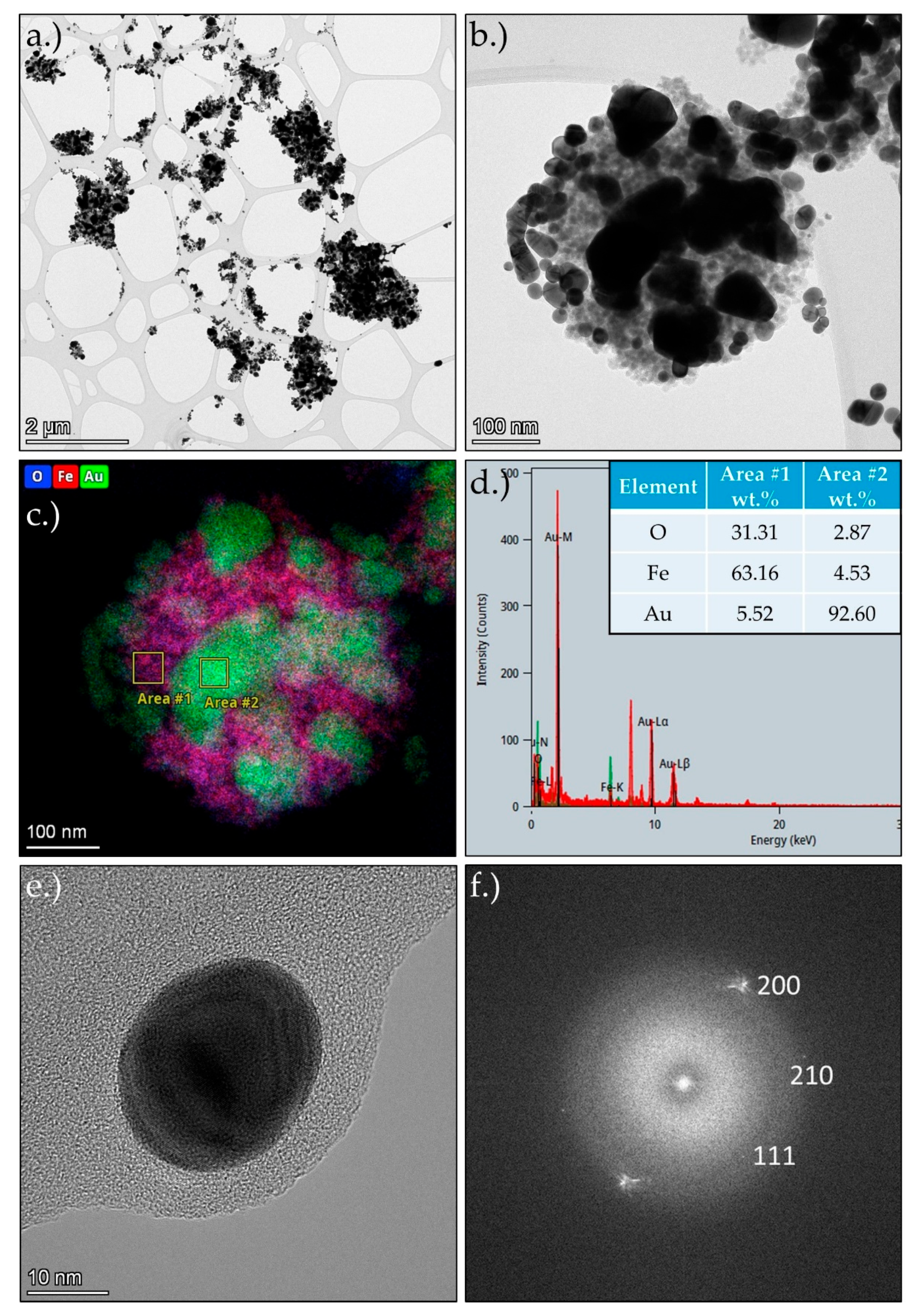
Figure 3 shows the TEM and STEM results of MNPs-Au, with a lower magnification overview of the produced particles in
Figure 3 a.) and a higher magnification image of a typical MNPs-Au particle in
Figure 3 b.). This section was examined additionally with EDS mapping and two selected area analyses in
Figure 3 c.)
Figure 3 and d.). The TEM images show clusters of smaller MNPs, covered with somewhat larger Au particles with spherical and irregular shapes. The MNPs have similar sizes as without the Au, in a range from 105 nm to 25 nm. They also appear to be aggregated, as before. The Au particles are larger, in a range of about 10 to 200 nm. The EDS mapping analysis shows a distribution of O, Fe and Au, wherein the O and Fe are seemingly overlapping. Additionally, C was detected, but was removed from the analysis, as its presence ess the result of the sample holder (TEM grid with holey the lacy carbon film) and the stabiliser used for the particle collection during the USP process (PVP stabiliser). Some separate Au nanoparticles were also present in the MNPs-Au sample. An example is shown in
Figure 3 e.), along with an FFT pattern of this particle in
Figure 3 f.). The spot pattern indicates a crystalline structure of the produced Au nanoparticles, with indices as shown in
Figure 3 e.).
3.2. SEM Analysis
In
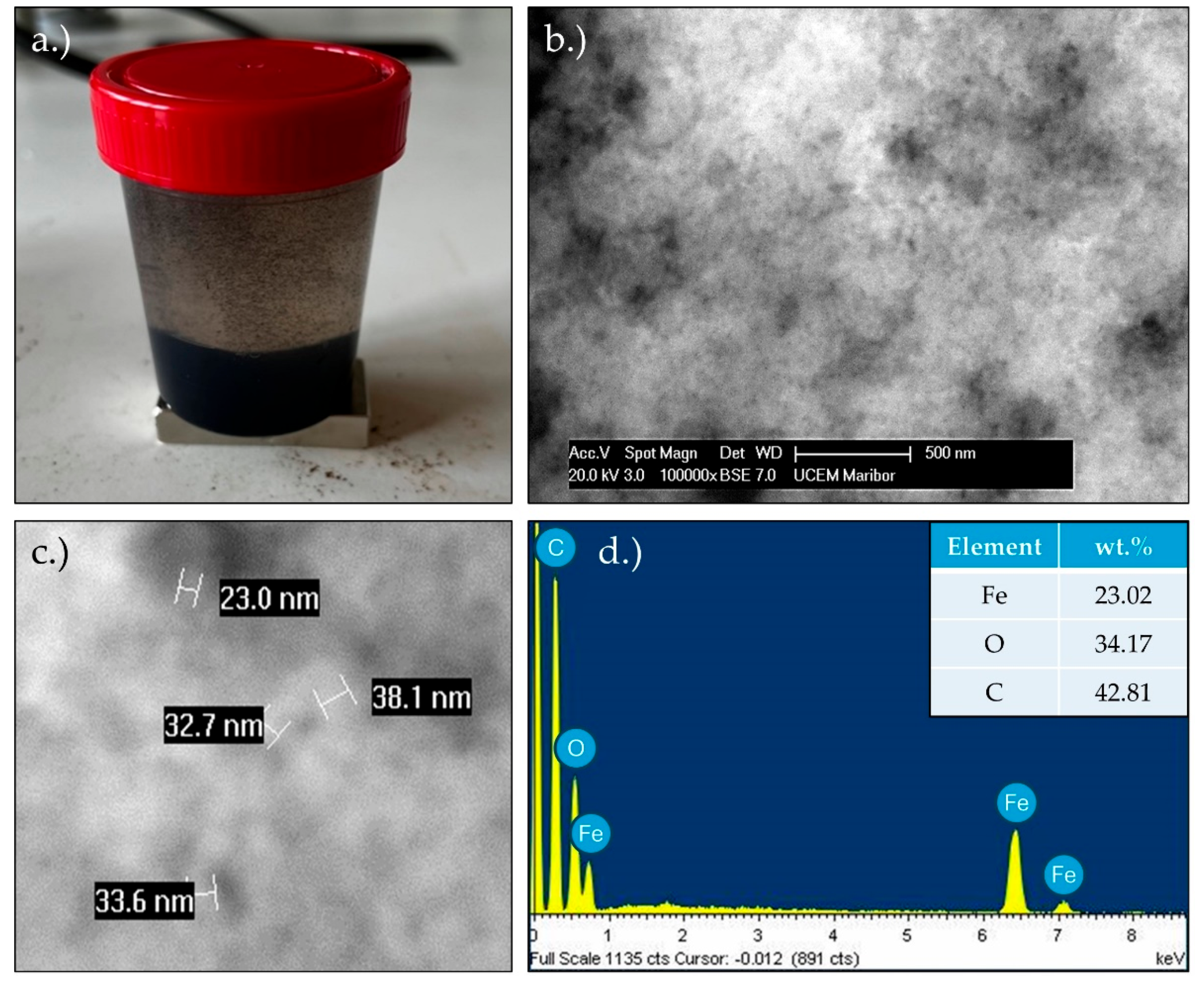
Figure 4 a.) we can see a dispersion of MNPs in water. The settling of the nanoparticles is clearly visible, in addition to some nanoparticles floating in the water.
Figure 4 b.) and
Figure 4 c.) showcase the results of the SEM analysis. The particle size is between 20 and 40 nm, which corresponds to the results of the TEM analysis. In the EDS analysis (
Figure 3.d)) of the MNPs, carbon and oxygen can be observed with the addition of iron. The carbon was present because of the graphite tape used to prepare the samples. The oxygen and iron are the result of the magnetic nanoparticles.
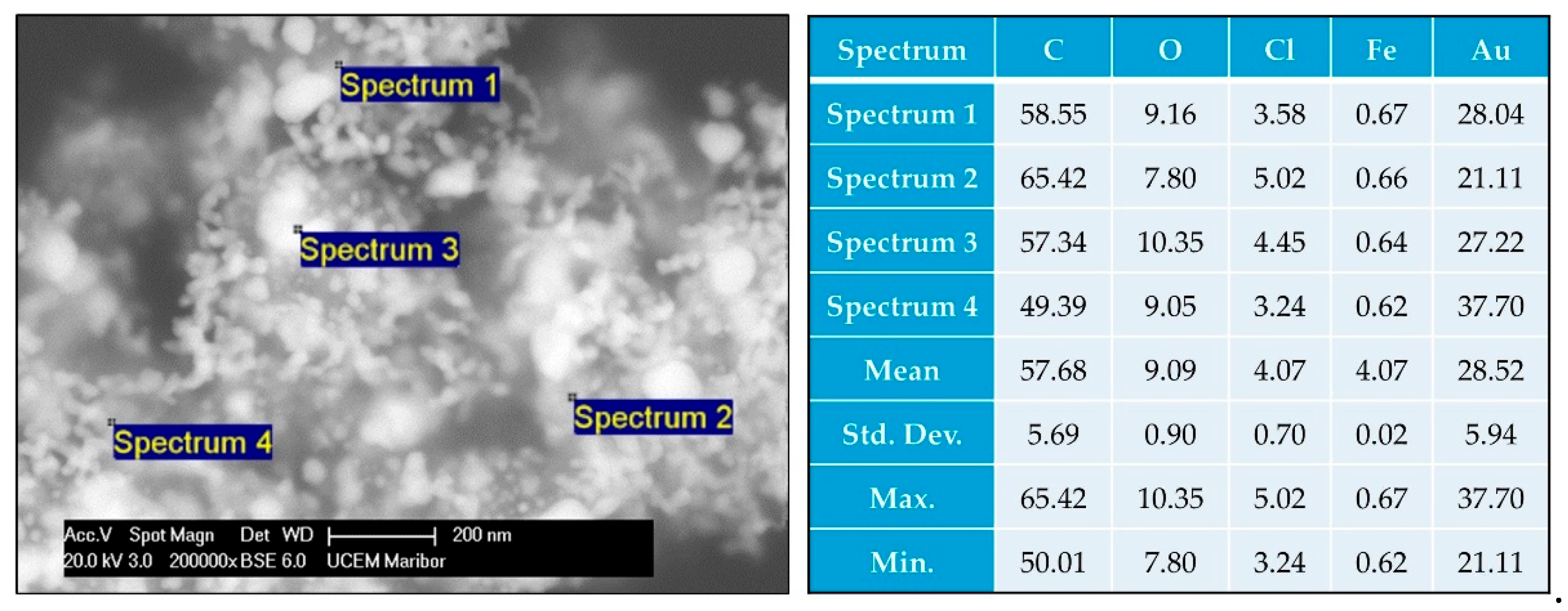
Figure 5 shows the SEM/EDS analysis performed on the prepared MNPs-Au particles. The particle structures are similar as with the TEM images, wherein the MNPs` clusters are covered with irregularly shaped Au particles, along with some individual Au nanoparticles present as separate entities. The EDS shows the presence of C, O, Cl, Fe and Au. Again, the carbon is present due to the graphite tape on which the sample was deposited, as well as due to the stabiliser PVP. Chlorine is a side product of the USP process, which was additionally collected from the USP gas flow, along with collection of the particles in the collection medium.
3.3. ICP-OES Analysis of the Prepared MNPs-Au Suspension
The resulting concentration of Fe and Au in the prepared MNPs-Au suspension is given in
Table 1.
3.4. DLS and Zeta Potential Analysis
In
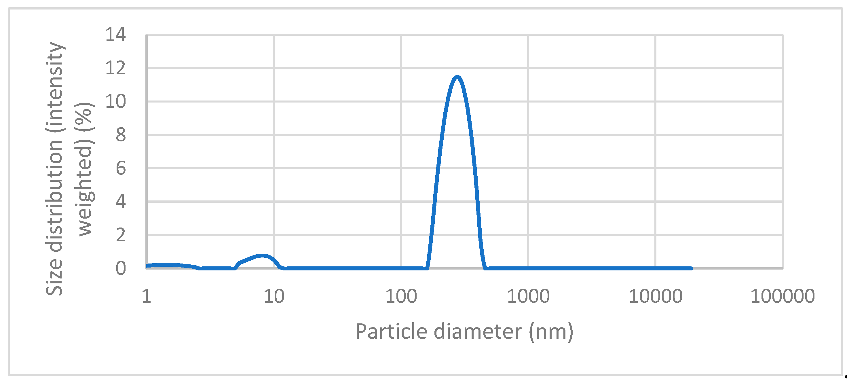
Figure 6 we can see the results of the dynamic light scattering (DLS) analysis of our magnetic nanoparticles that were coated with gold (MNPs-Au). As we can see on the graph, the largest peak can be seen at values 200 – 300 nm, which suggests that most particles have a diameter between 200 and 400 nm, with the average hydrodynamic diameter being 279,007 nm. We can also see two additional, but much smaller, peaks, at values 1-3 nm and 8 – 10 nm, which means our sample contains some much smaller nanoparticles. However, the concentration of these nanoparticles is relatively low, which is proven by the fact that these peaks have low intensity.
In
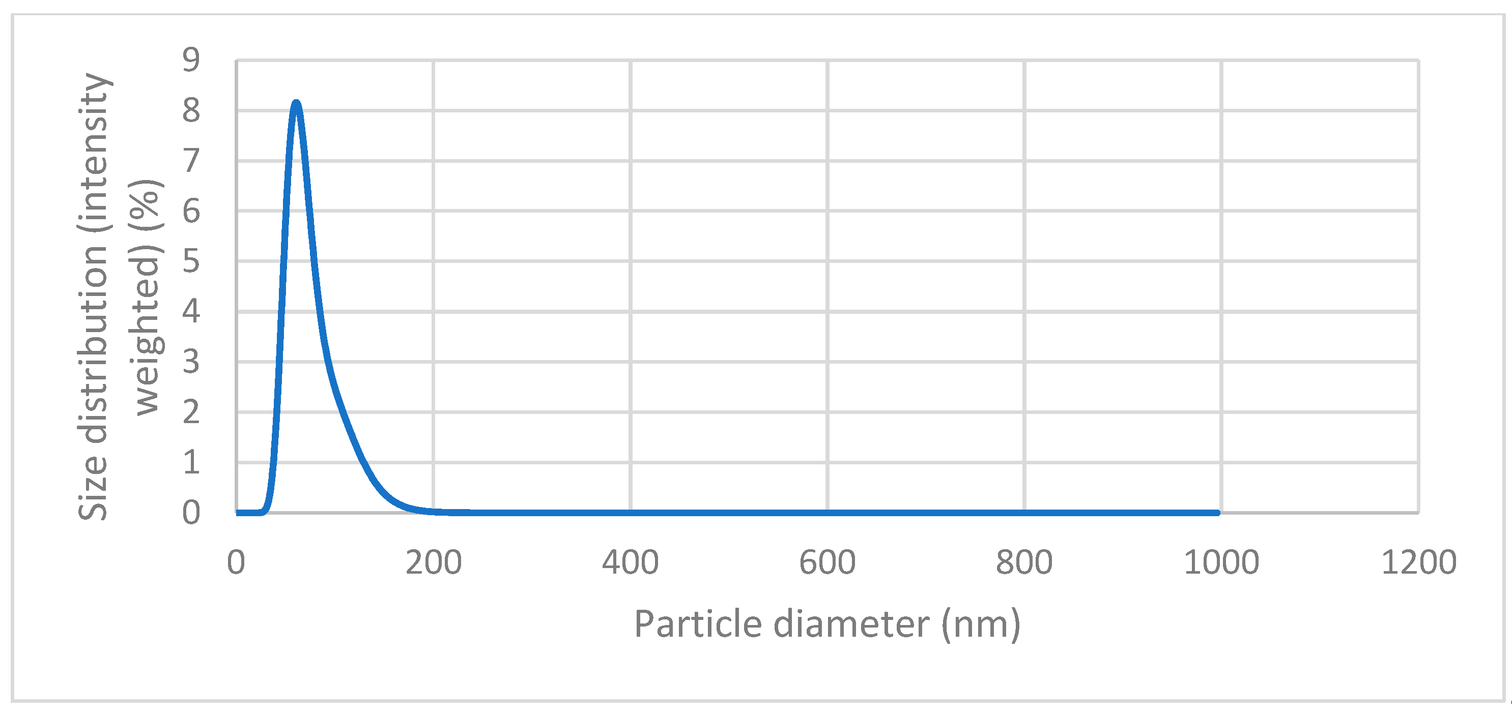
Figure 7 we can see the graph of the DLS analysis of the magnetic nanoparticles, which is the result of the DLS measurement. The peak can be seen at values around 50 – 100 nm, with the highest point around 65 nm. This peak indicates that the nanoparticles are relatively monodisperse, meaning that they have a consistent size around this value. We can also observe no other peak that would indicate the presence of much larger particles.
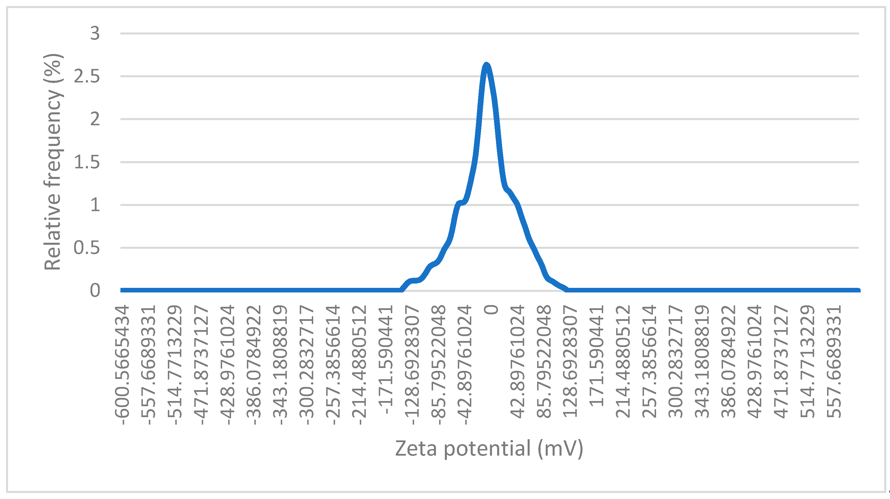
Figure 8 represents the results of the zeta potential measurement of the magnetic nanoparticles coated with gold. On the graph we can see a peak, with its centre at around 0 mV with a median zeta potential of -0,49 mV. This suggests that the nanoparticles exhibit a relatively neutral surface charge. The distribution of zeta potential is very narrow, meaning that most of the particles have very similar surface charge properties, as reflected in the small variance around the peak. Low zeta potential (close to 0 mV) implies poor stability. The optimal zeta potential for stable suspensions is usually around -30 mV or +30 mV. The zeta potential being close to zero is most likely the result of the gold coating.
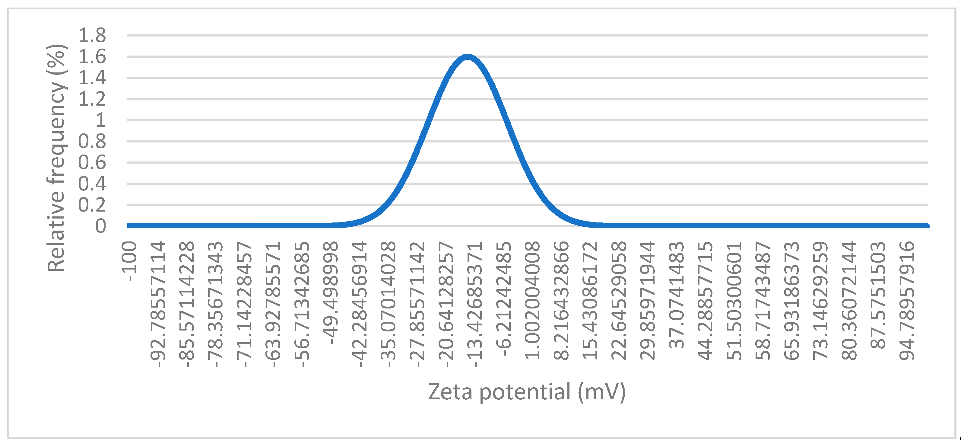
Figure 9 represents a dynamic light scattering (DLS) measurement of the magnetic nanoparticles. The values on the x-axis range from approximately -100 mV to +100 mV, with the peak centred close to -15 mV. This suggests that most of the particles in the suspension have a zeta potential near neutral. The fact that the zeta potential is close to 0 mV suggests that the magnetic nanoparticle suspension is close to its isoelectric point (which is around pH 6,5 - 7 for Fe
3O
4). Since the zeta potential is near 0, the electrostatic repulsion between the particles is minimal. This indicates that the particles are less stable and prone to aggregation, as there is not enough repulsion to keep the particles apart. The peak is relatively sharp, which indicates that most particles have a similar surface charge.
3.4. Magnetic Properties
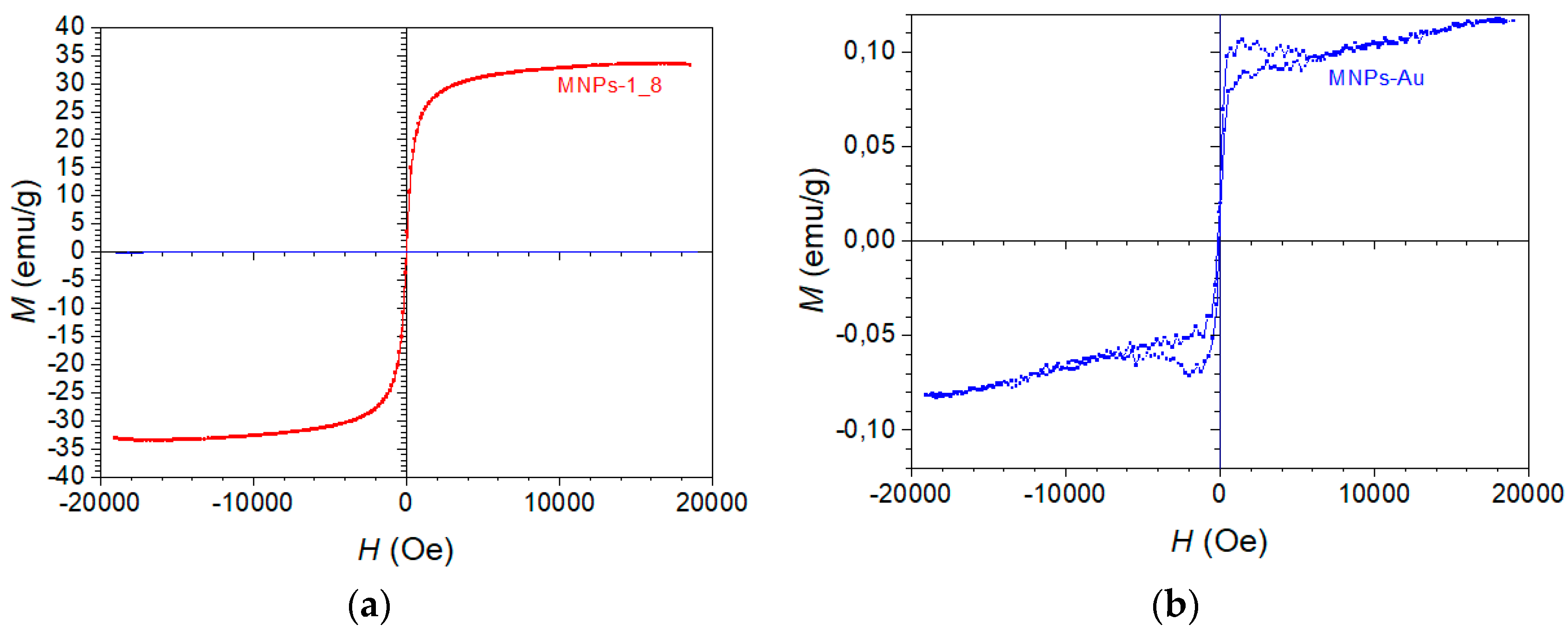
Figure 10 (a) represents a magnetic hysteresis loop, labelled “MNPs-1_8”. The x-axis represents the external magnetic field H in Oersted’s (Oe), from -20,000 to +20,000 Oe. The y-axis represents the magnetisation M in emu/g, which extends from -40 emu/g to +40 emu/g. The curve is strongly S-shaped, and appears to saturate at both ends (around 35-40 emu/g for large positive and negative fields). There is no visible coercivity or remanence (the point at which the loop crosses the x-axis is very close to zero), which implies that this material exhibits superparamagnetic behaviour.
Figure 10 (b) also shows a typical “S-shaped” curve, characteristic of superparamagnetic or weakly ferromagnetic materials. In this case, the loop has no significant coercivity (the field required to bring the magnetization to zero), and no remanent magnetisation (residual magnetism when the external field is removed). This indicates that the material aligns quickly with and demagnetises with the external field, suggesting superparamagnetic behaviour. There is no significant hysteresis loop area, indicating very low or no coercivity and remanent magnetisation. This implies the nanoparticles are superparamagnetic at room temperature, meaning they only exhibit magnetism in the presence of an external field, and lose their magnetisation once the field is removed. The curve appears to saturate at around ± pm 0.10 emu/g for large magnetic fields (close to 20,000 Oe). This represents the maximum magnetisation of the MNPs-Au in the presence of a strong magnetic field, beyond which further increases in the magnetic field do not increase magnetization significantly.
The saturation magnetisation of MNPs-1_8 is much higher compared to Figure b, reaching about 35 emu/g. This suggests that the MNPs-1_8 sample has a much stronger magnetic core or a higher concentration of magnetic material. In contrast to the MNPs-Au sample, which only reached a saturation magnetisation of around 0.1 emu/g, this sample has much higher magnetisation (35 emu/g).
4. Discussion
The MNPs prepared with the coprecipitation method had a spherical and some irregular shapes, within a size range of about 10 to 40 nm and a highly crystalline structure. Aggregation was present in the MNPs, forming clusters of these particles in the suspension. They exhibited superparamagnetic behaviour.
Using these particles for coating with Au in the USP process yielded the presented MNPs-Au particles. These were not uniform, but had a structure of the MNPs` clusters, covered with spherical and irregular Au particles, along with individual separate Au nanoparticles in the final suspension. The Au particle sizes were in the range of 10 to 200 nm, with a polycrystalline structure. The different examinations showed that the MNPs retained their sizes, shapes and aggregation properties. The MNPs-Au particles had a weaker magnetisation, but still had a superparamagnetic behaviour, owing to the presence of MNPs, as Au does not have this property.
Earlier, research into the USP production of Fe particles coated with Au was performed with dissolved Fe salts (Fe acetate, nitrate and chloride) and Au salts in the precursor solution. The results showed that the Fe particle forms depended greatly on the precursor used, forming meshes, spherical or irregular structures of Fe oxide nanoparticles. The Au particles were deposited on the Fe oxide particles with varying degrees of coverage, sizes and shapes, depending on the process parameters and salt concentrations in the precursor solution. A full core-shell Fe-Au structure was not achieved in these investigations, and similar structures were formed as with the present investigation. The broad miscibility gap between Fe and Au resulted in complete phase separation between these two elements during the particle synthesis. This is good for separating the core and shell material during formation, but also results in Au nanoparticles clumping on top of the Fe oxide particles, or the formation of completely separate Fe and Au nanoparticles.
In the present investigation, already prepared MNPs were used as seeds in the USP precursor solution for the MNPs-Au synthesis. Depending on the coprecipitation method, MNPs with 1/8th of the chosen mass of iron sulphates were determined as the most appropriate for further processing with USP. These MNPs had the least aggregation and smallest sizes, making them the most suitable for use with the ultrasonic membrane. The sizes of the MNPs seeds are required to be a small as possible for generating aerosol droplets and transport of these droplets into the USP tube furnace. With large particles sizes in the precursor, the generated droplets do not contain these particles, as they are left behind in the precursor solution. The MNPs clusters should also be avoided in the precursor solution, in order to provide for aerosol droplets containing the seeds for Au coating. The different characterisations showed a higher Au particle content as compared to Fe, with a larger mass quantity of Au present, as confirmed by ICP-OES. There was 5.8x more Au particle mass present than MNPs in the final MNPs-Au suspension. The initial concentration ratio for Fe and Au in the precursor solution was 4x more Au than Fe. This indicates that some MNPs may have been left behind in the precursor solution during droplet generation. Additional optimisation of the precursor solution containing MNPs is needed, in order to improve the uptake of these particles in the aerosol droplets, such as further reduction of the particle sizes and prevention of particle cluster formations.
The structures of the final MNPs-Au particles are similar to previous experiments for the production of core-shell Fe-Au nanoparticles. The main difference is in the Fe particle structure, wherein we have obtained MNPs clusters, covered with Au particles. Previously, solid Fe particles were obtained, covered with Au particles. Similar Au particle formation mechanisms were observed on top of the Fe. In order to produce more uniformly covered MNPs, the surface of the Fe particles needs to be adjusted for a more favourable growth of Au during the USP process. The presence of chlorine in some of the analyses also indicates an unoptimised USP process, wherein some unreacted Au salts may also be present in the final collection medium. Additional optimisation steps are needed for determination of parameters for the synthesis of MNPs-Au particles. These initial investigations of using MNPs seeds have given further insight and possible directions into investigating the possibilities of producing MNPs-Au particles with USP (optimisation of the MNPs precursor for USP, surface modification of the MNPs).
The magnetic properties of the MNPs were retained in the final MNPs-Au structure, although , the magnetisation was diminished by the Au particle content. By overcoming the issues with ultrasonic droplet generation with more optimal MNPs` sizes in the precursor solution, and better Au coverage on the MNPs, the magnetic properties may be preserved further for better performance.
5. Conclusions
In this study, we synthesised magnetite nanoparticles (MNPs) successfully using the coprecipitation method, and, subsequently, coated them with gold through the USP technique. The resulting MNPs-Au particles exhibited a range of sizes and structures, retaining the superparamagnetic behaviour of the original MNPs, while demonstrating a reduction in magnetisation due to the added Au content. The characterisation analyses confirmed that the MNPs maintained their size and shape despite aggregation, and the Au particles presented a polycrystalline structure with sizes ranging from 10 to 200 nm.
The findings indicate that the choice of precursor materials influences the morphology and coverage of Au on the MNPs significantly. Our results showed a notable mass ratio of Au to MNPs in the final suspension, underscoring the need for further optimisation of the precursor solution to enhance the uniformity of Au coverage on the MNPs. Additionally, the study highlights the importance of minimising particle aggregation and optimising particle size in the precursor solution, to improve aerosol droplet generation during the USP process.
Overall, these investigations provide valuable insights into the synthesis of MNPs-Au particles, and lay the groundwork for future optimisation strategies aimed at enhancing the magnetic properties and functionalisation of these nanoparticles for applications in biomedical fields. Further research will focus on refining the USP process parameters, and exploring surface modification techniques to achieve better control over the MNPs-Au structures, ultimately improving their performance in targeted drug delivery and magnetic hyperthermia applications.
Author Contributions
“Conceptualization, R.R. and L.K.; methodology, L.K.; K.P.Č., R.R..; software, P.M..; validation, K.P.Č. and R.R.; formal analysis, L.K. and D.F.; investigation, L.K.; K.P.Č., P.M. and R.R; resources, K.P.Č. and R.R.; data curation, P.M.; writing—original draft preparation, L.K. and P.M.; writing—review and editing, P.M., D.F. and R.R.; visualization, L.K. and P.M.; supervision, R.R..; project administration, R.R.; funding acquisition, R.R.. All authors have read and agreed to the published version of the manuscript.
Funding
This research and APC was funded by the Slovenian Research Agency ARIS (P2-0120 and P2-0118 Research Programs).
Data Availability Statement
We encourage all authors of articles published in MDPI journals to share their research data.
Acknowledgments
We would like to thank Žiga Jelen for his administrative assistance.
Conflicts of Interest
The authors declare no conflicts of interest.
References
- G.F. Stiufiuc, R.I. Stiufiuc, Magnetic Nanoparticles: Synthesis, Characterization, and Their Use in Biomedical Field, Applied Sciences (Switzerland) 14 (2024). [CrossRef]
- A. Ali, T.; Shah, R. Ullah, P. Zhou, M. Guo, M. Ovais, Z. Tan, Y.K. Rui, Review on Recent Progress in Magnetic Nanoparticles: Synthesis, Characterization, and Diverse Applications, Front Chem 9 (2021). [CrossRef]
- C. Shasha, K.M. Krishnan, Nonequilibrium Dynamics of Magnetic Nanoparticles with Applications in Biomedicine, Advanced Materials 33 (2021). [CrossRef]
- D.D. Stueber, J. Villanova, I. Aponte, Z. Xiao, V.L. Colvin, Magnetic nanoparticles in biology and medicine: Past, present, and future trends, Pharmaceutics 13 (2021). [CrossRef]
- F. Soetaert, P. Korangath, D. Serantes, S. Fiering, R. Ivkov, Cancer therapy with iron oxide nanoparticles: Agents of thermal and immune therapies, Adv Drug Deliv Rev 163–164 (2020) 65–83. [CrossRef]
- K. Luo, J. Zhao, C. Jia, Y. Chen, Z. Zhang, J. Zhang, M. Huang, S. Wang, Integration of Fe3O4 with Bi2S3 for Multi-Modality Tumor Theranostics, ACS Appl Mater Interfaces 12 (2020) 22650–22660. [CrossRef]
- O.L. Gobbo, K. Sjaastad, M.W. Radomski, Y. Volkov, A. Prina-Mello, Magnetic nanoparticles in cancer theranostics, Theranostics 5 (2015) 1249–1263. [CrossRef]
- I. Belyanina, O.; Kolovskaya, S.; Zamay, A.; Gargaun, T.; Zamay, A.; Kichkailo, Targeted magnetic nanotheranostics of cancer, Molecules 22 (2017). [CrossRef]
- D. Chang, M.; Lim, J.A.C.M. Goos, R. Qiao, Y.Y. Ng, F.M. Mansfeld, M. Jackson, T.P. Davis, M. Kavallaris, biologically targeted magnetic hyperthermia: Potential and limitations, Front Pharmacol 9 (2018). [CrossRef]
- J. Xie, G. Liu, H.S. Eden, H. Ai, X. Chen, Surface-engineered magnetic nanoparticle platforms for cancer imaging and therapy, Acc Chem Res 44 (2011) 883–892. [CrossRef]
- T.A.P. Rocha-Santos, Sensors and biosensors based on magnetic nanoparticles, TrAC - Trends in Analytical Chemistry 62 (2014) 28–36. [CrossRef]
- A.K. Gupta, M. Gupta, Synthesis and surface engineering of iron oxide nanoparticles for biomedical applications, Biomaterials 26 (2005) 3995–4021. [CrossRef]
- K.C. De Souza, G.F. Andrade, I. Vasconcelos, I.M. De Oliveira Viana, C. Fernandes, E.M.B. De Sousa, Magnetic solid-phase extraction based on mesoporous silica-coated magnetic nanoparticles for analysis of oral antidiabetic drugs in human plasma, Materials Science and Engineering C 40 (2014) 275–280. [CrossRef]
- J.J. Gooding, S. Ciampi, The molecular level modification of surfaces: From self-assembled monolayers to complex molecular assemblies, Chem Soc Rev 40 (2011) 2704–2718. [CrossRef]
- D. Yang, X.; Pang, Y. He, Y. Wang, G. Chen, W. Wang, Z. Lin, Precisely Size-Tunable Magnetic/Plasmonic Core/Shell Nanoparticles with Controlled Optical Properties, Angewandte Chemie 127 (2015) 12259–12264. [CrossRef]
- S. Moraes Silva, R. Tavallaie, L. Sandiford, R.D. Tilley, J.J. Gooding, Gold coated magnetic nanoparticles: From preparation to surface modification for analytical and biomedical applications, Chemical Communications 52 (2016) 7528–7540. [CrossRef]
- I.Y. Goon, L.M.H. Lai, M. Lim, P. Munroe, J.J. Gooding, R. Amal, Fabrication and dispersion of gold-shell-protected magnetite nanoparticles: Systematic control using polyethyleneimine, Chemistry of Materials 21 (2009) 673–681. [CrossRef]
- Y.R. Cui, C. Hong, Y.L. Zhou, Y. Li, X.M. Gao, X.X. Zhang, Synthesis of orientedly bioconjugated core/shell Fe3O 4@Au magnetic nanoparticles for cell separation, Talanta 85 (2011) 1246–1252. [CrossRef]
- A. Ahmadi, H. Shirazi, N. Pourbagher, A. Akbarzadeh, K. Omidfar, An electrochemical immunosensor for digoxin using core-shell gold coated magnetic nanoparticles as labels, Mol Biol Rep 41 (2014) 1659–1668. [CrossRef]
- S. Kayal, R.V. Ramanujan, Anti-cancer drug loaded iron-gold core-shell nanoparticles (Fe@Au) for magnetic drug targeting, J Nanosci Nanotechnol 10 (2010) 5527–5539. [CrossRef]
- M. Kumagai, T.K. Sarmat, H. Cabral, S. Kaida, M. Sekino, N. Herlambang, K. Osada, M.R. Kano, N. Nishiyama, K. Kataoka, Enhanced in vivo magnetic resonance imaging of tumors by PEGylated iron-oxide-gold core-shell nanoparticles with prolonged blood circulation properties, Macromol Rapid Commun 31 (2010) 1521–1528. [CrossRef]
- H. Salehizadeh, E. Hekmatian, M. Sadeghi, K. Kennedy, Synthesis and characterization of core-shell Fe 3 O 4-gold-chitosan nanostructure, 2012. http://www.jnanobiotechnology.com/content/10/1/3.
- S. Moraes Silva, R. Tavallaie, L. Sandiford, R.D. Tilley, J.J. Gooding, Gold coated magnetic nanoparticles: From preparation to surface modification for analytical and biomedical applications, Chemical Communications 52 (2016) 7528–7540. [CrossRef]
- E.E. Carpenter, C. Sangregono, C.J. O’connor, Effects Of Shell Thickness on Blocking Temperature Of Nanocomposites Of Metal Particles With Gold Shells, n.d.
|
Disclaimer/Publisher’s Note: The statements, opinions and data contained in all publications are solely those of the individual author(s) and contributor(s) and not of MDPI and/or the editor(s). MDPI and/or the editor(s) disclaim responsibility for any injury to people or property resulting from any ideas, methods, instructions or products referred to in the content. |
© 2024 by the authors. Licensee MDPI, Basel, Switzerland. This article is an open access article distributed under the terms and conditions of the Creative Commons Attribution (CC BY) license (https://creativecommons.org/licenses/by/4.0/).
