Submitted:
27 September 2024
Posted:
29 September 2024
You are already at the latest version
Abstract
Keywords:
1. Introduction
2. Materials and Methods
2.1. Mechanical System
2.2. Electronics
2.3. Testing and Validation
2.3.1. Calibration Process
2.3.2. Validation Process
3. Results
4. Discussion
5. Conclusions
Author Contributions
Funding
Institutional Review Board Statement
Informed Consent Statement
Data Availability Statement
Conflicts of Interest
Appendix A
| No. | Design file name | File type | Technology | Material |
|---|---|---|---|---|
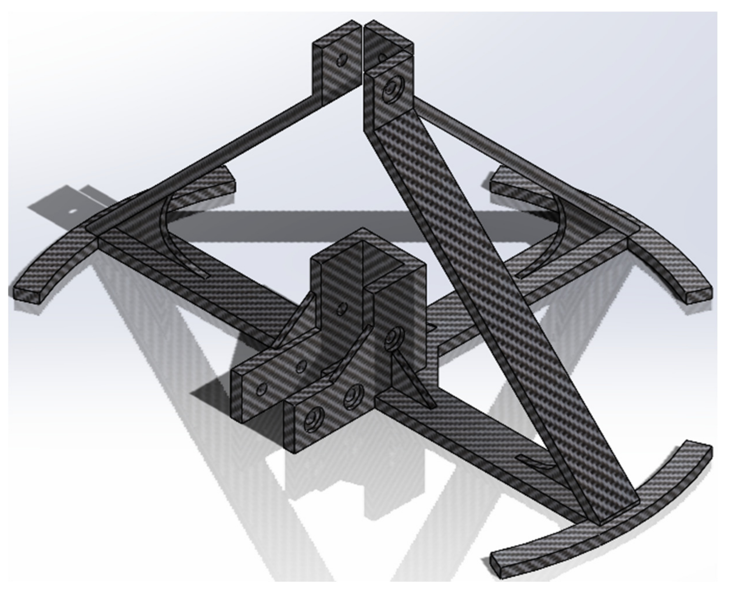
| 1 | Stand | STL&STEP | FFF 3D printing | PETG |
| 2 | Linear support | STL&STEP | FFF 3D printing | PETG |
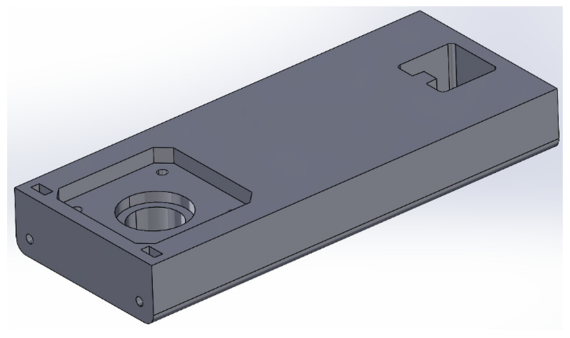
| 3 | Motor mount | STL&STEP | FFF 3D printing | PETG |
| 4 | Flange support | STL&STEP | FFF 3D printing | PETG |
| 5 | Loadcell fit | STL&STEP | FFF 3D printing | PETG |
| 6 | Shaft loadcell coupler | STL&STEP | FFF 3D printing | PETG |
| 7 | Cutter connector | STL&STEP | FFF 3D printing | PETG |
| 8 | Blade fix | STL&STEP | FFF 3D printing | PETG |
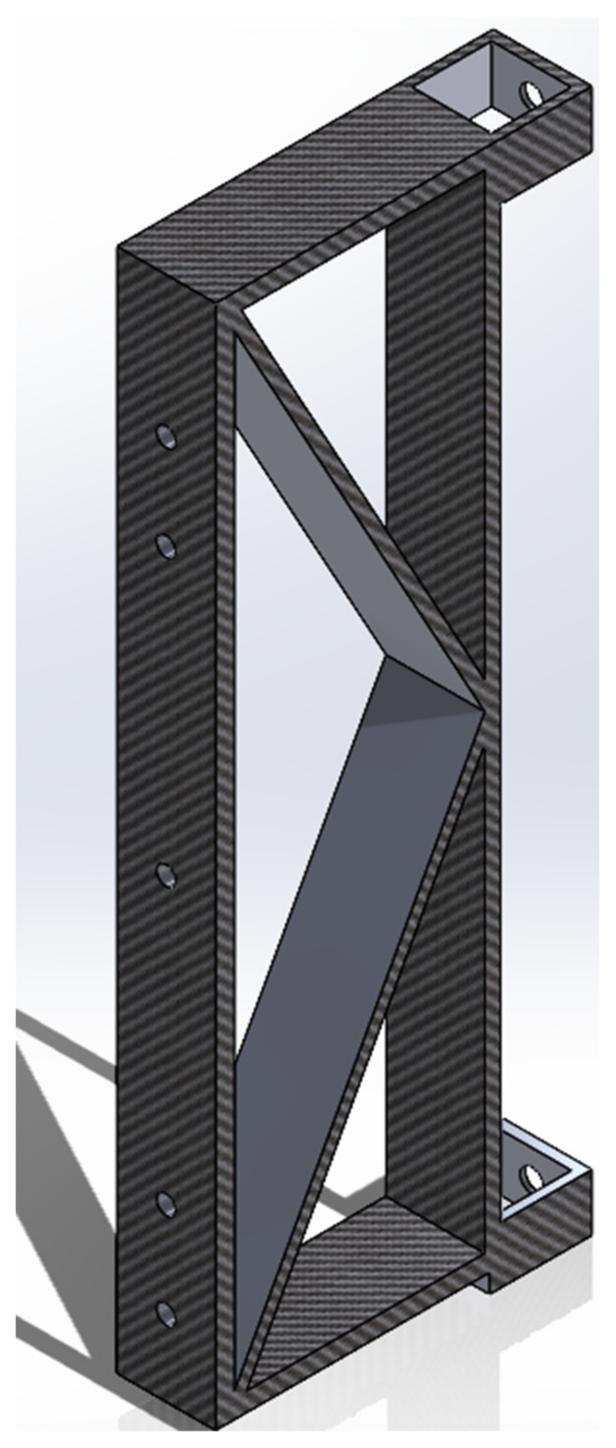
| 9 | Extra frame | STL&STEP | FFF 3D printing | PETG |
| 10 | Extra frame b | STL&STEP | FFF 3D printing | PETG |
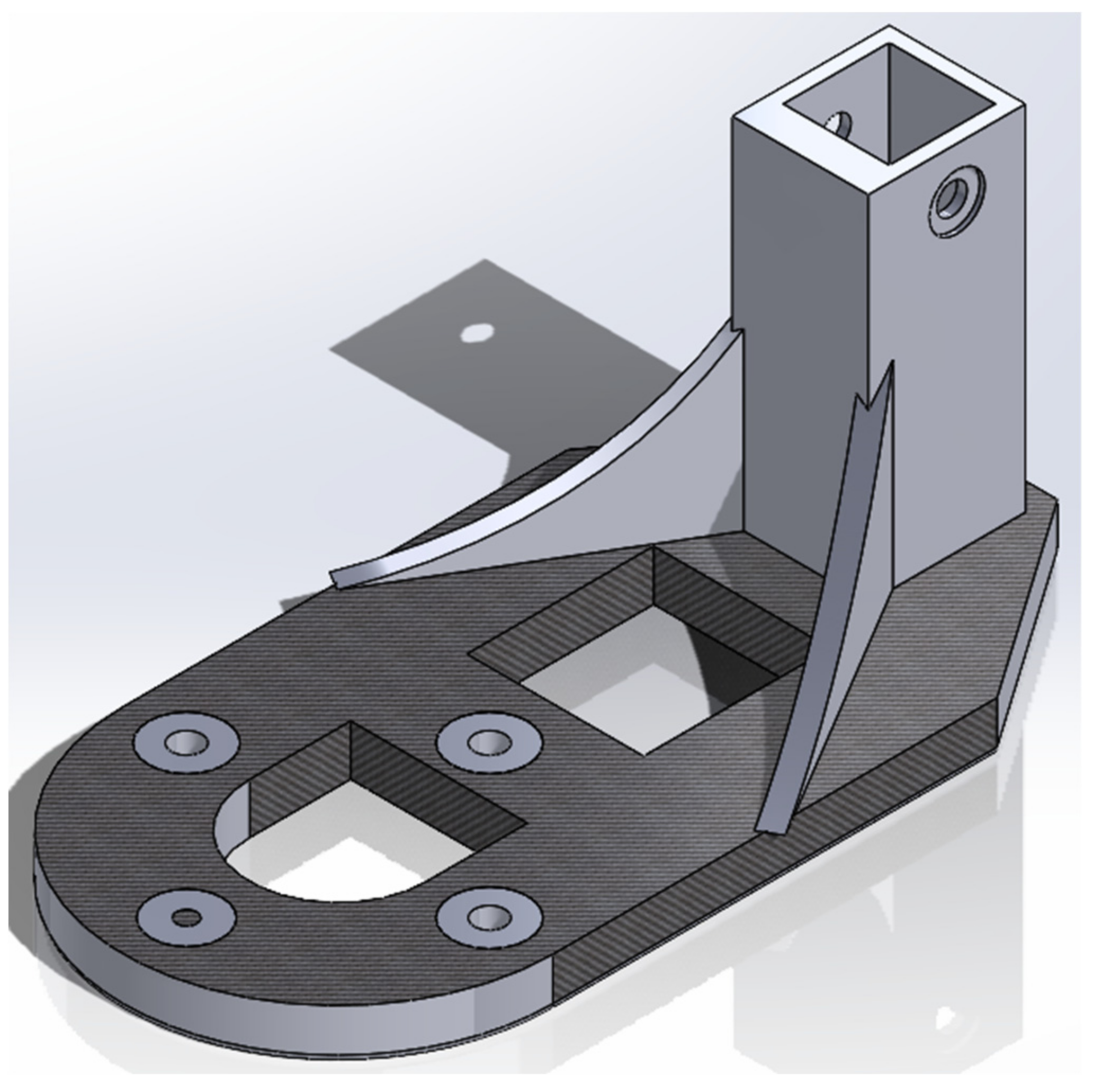
| 11 | Foot support | STL&STEP | FFF 3D printing | PETG |
| 12 | Housing | STL&STEP | FFF 3D printing | PETG |
| 13 | Insulation housing | STL&STEP | FFF 3D printing | PC |
| 14 | Cap band | STL&STEP | FFF 3D printing | PC |
| 15 | Piston guide | STL&STEP | FFF 3D printing | PETG |
| 16 | Piston tip guide | STL&STEP | FFF 3D printing | PETG |
| 17 | Scale housing | STL&STEP | FFF 3D printing | PETG |
| 18 | Scale plate | STL&STEP | FFF 3D printing | PETG |
| 19 | Block | STL&STEP | FFF 3D printing | PETG |
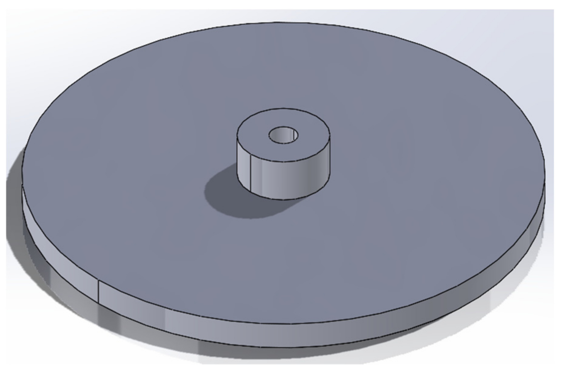
| 20 | Calibration part | STL&STEP | FFF 3D printing | PETG |
| 21 | PCB | zip | // | |
| 22 | MFI | ino | // |
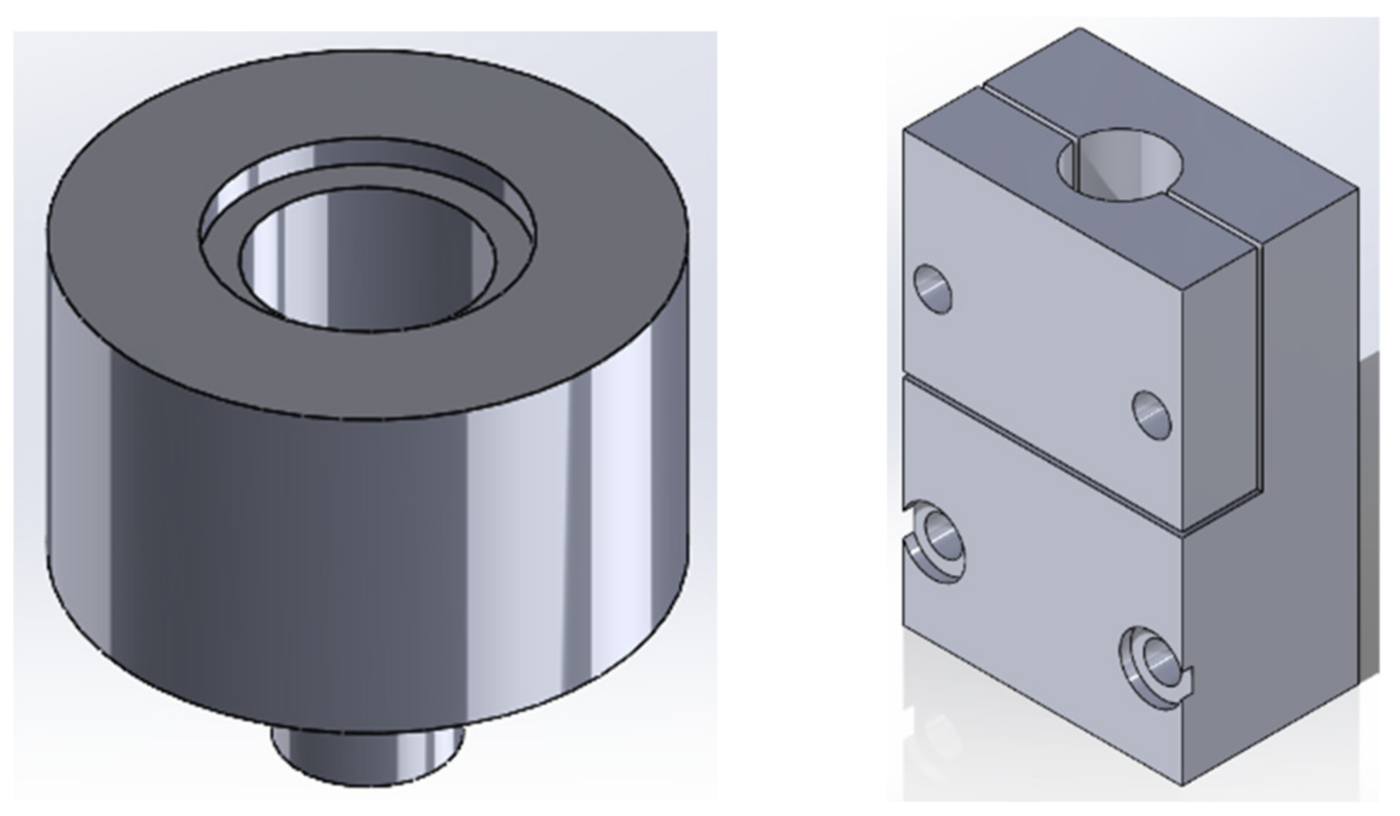
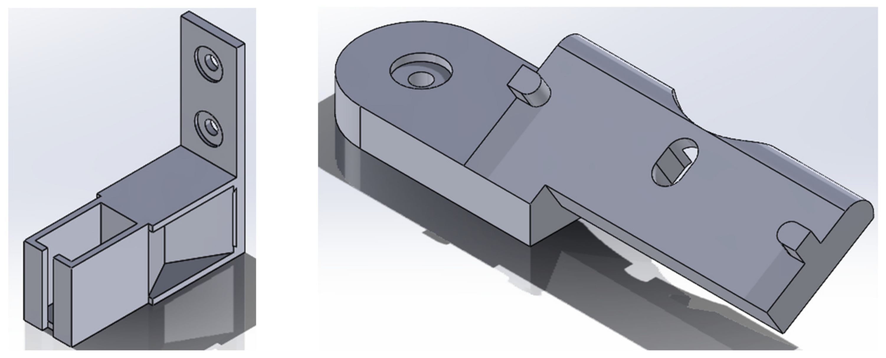
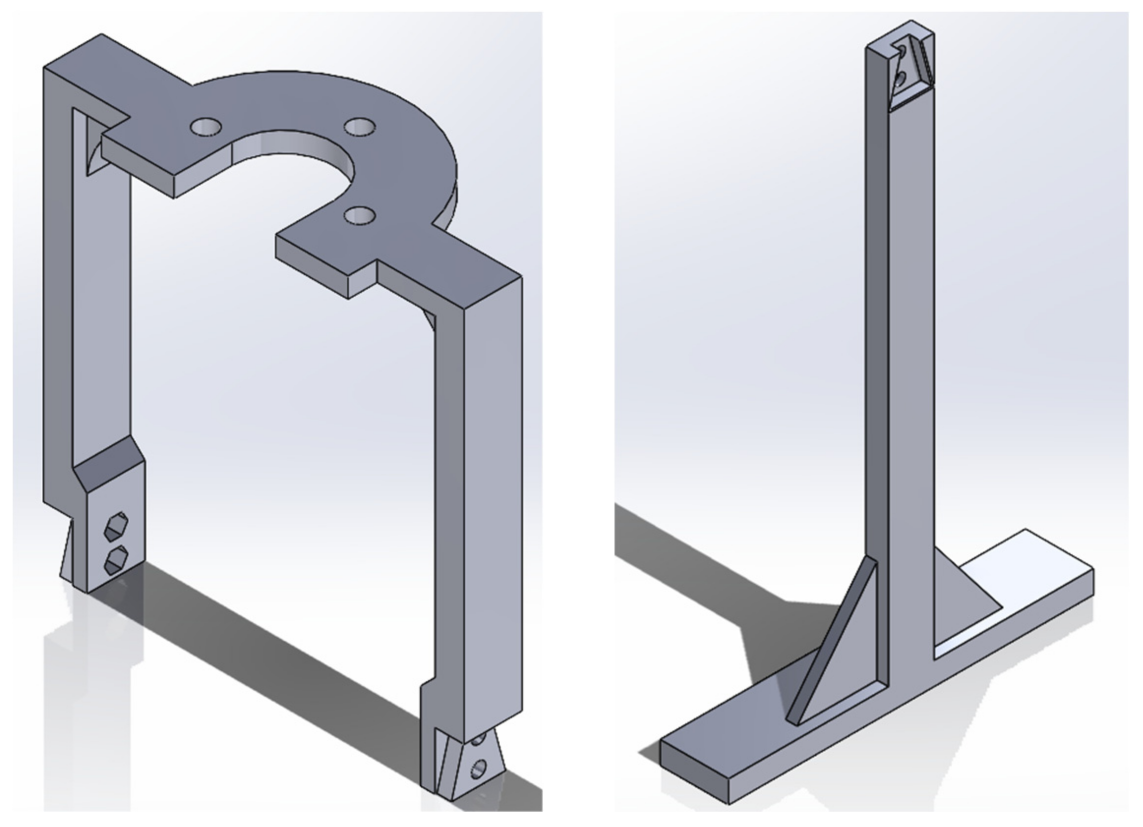
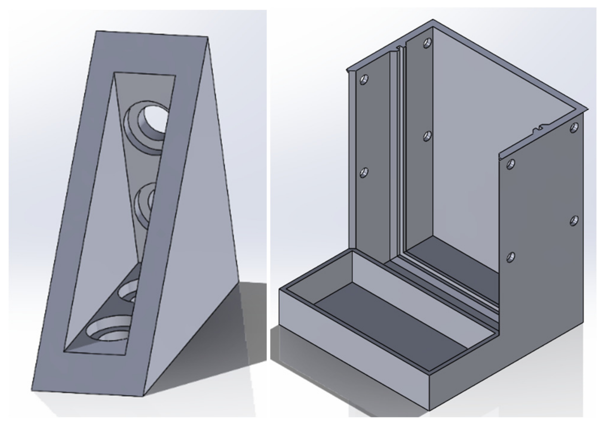

| No. | Name | Model number | Quantity | Cost per unit (CAD) | Source |
|---|---|---|---|---|---|
| 1 | PCB | 1 | 10.00 | JLCPCB | |
| 2 | Control board | Teensy board 4.0 | 1 | 23.80 | Teensy.com |
| 3 | Motor driver | TMC2130 | 1 | 10.0 | Amazon |
| 4 | Amplifier | HX711 | 2 | 6.00 | Amazon |
| 5 | ADC | MAX31855KASA | 1 | 12.66 | Digikey |
| 6 | LDO regulator | AMS1117 | 1 | 0.85 | Digikey |
| 7 | Force sensor | DYMH-103 | 1 | 70.42 | AliExpress |
| 8 | Loadcell | 100 g | 1 | 10.79 | Amazon |
| 9 | SMD Resistor | 10 k | 2 | 0.15 | Digikey |
| 10 | Capacitors c1 | 100 uF | 1 | 0.48 | Digikey |
| 11 | Capacitors c2 | 22 uF | 1 | 0.21 | Digikey |
| 12 | Capacitors c3 | 0.01 uF | 1 | 0.14 | Digikey |
| 13 | Capacitors c4 | 10 uF | 1 | 0.14 | Digikey |
| 14 | Ferrite Beads | FERRITE BEAD 120 OHM 0603 1LN | 2 | 0.18 | Digikey |
| 15 | Thermocouple | 240-080 | 1 | 15.80 | Digikey |
| 16 | Connecters | 8 | 0.10 | Amazon | |
| 17 | Motor | Nema 17 Non-captive Linear stepper motor | 1 | 25.84 | AliExpress |
| 18 | Servomotor | 1 | 2.90 | Amazon | |
| 19 | Power supply | 110v AC to 12V DC | 1 | 22.88 | Amazon |
| 20 | Relay module | 12V | 1 | 1.90 | Amazon |
| 21 | Wires | Jump wires | 10 | 0.10 | Amazon |
| 22 | High temperature-resist wires | Awclub Mica | 0.164 ft | 0.75/ft | Amazon |
| 23 | High temperature-resist connectors | O Type and U Type | 8 | 0.05 | Amazon |
| 24 | Nichrome wire | 50’ nichrome 80 wire | 1 | 9.47 | Master wire supply |
| 25 | Band heater | 12V 40W | 1 | 20.00 | Filastruder |
| No. | Name | Model number | Quantity | Cost per unit (CAD) | Source | Material |
|---|---|---|---|---|---|---|
| 1 | Bolts b1 | M6-5mm | 19 | 0.10 | Amazon | Steel |
| 2 | Bolts b2 | M3-20mm | 8 | 0.10 | Amazon | Steel |
| 3 | Bolts b3 | M6-40mm | 3 | 0.10 | Amazon | Steel |
| 4 | Bolts b4 | M2-8mm | 4 | 0.10 | Amazon | Steel |
| 5 | Bolts b5 | M3-15mm | 3 | 0.10 | Amazon | Steel |
| 6 | Nuts n1 | M6 | 3 | 0.24 | Amazon | Steel |
| 7 | Nuts n2 | M3 | 3 | 0.10 | Amazon | Steel |
| 8 | Nuts n3 | M2 | 2 | 0.09 | Amazon | Steel |
| 9 | T-nuts t1 | M6, 20x20 | 19 | 0.20 | Amazon | Steel |
| 10 | Serrated Flange Lock Nut | ¼ inch | 1 | 0.80 | Amazon | Steel |
| 11 | Self-lock nut | ¼ inch | 1 | Amazon | Steel | |
| 12 | Washers w1 | M6 | 4 | 0.10 | Amazon | Steel |
| 13 | Washer w2 | M3 | 2 | 0.10 | Amazon | Steel |
| 14 | Heat tube | ½ inches, | 1 | 20.00 | McMaster-Carr | Steel |
| 15 | cap | ½ inches, hex | 1 | 5.00 | McMaster-Carr | Copper |
| 16 | Aluminum profile a1 | 20x20 | 75 mm | 0.013/mm | McMaster-Carr | Aluminum |
| 17 | Aluminum profile a2 | 20x20 | 30 mm | 0.013/mm | McMaster-Carr | Aluminum |
| 18 | Linear rail | 350mm | 2 | 0.18 | Amazon | Steel |
| 19 | Blade | 240-080 | 1 | 15.80 | McMaster-Carr | Steel |
| 20 | Piston rod | ¼ inches, 12 inches length | 2 | 1.50 | Home Depot | Steel |
| 21 | O-ring | OD5/8 | 1 | 0.26 | McMaster-Carr | Silicon |
| 22 | Capton tape | 1 | 2.90 | Amazon | Mixed | |
| 23 | Shaft Coupler | ¼ inch | 1 | 3.00 | Amazon | Steel |
| 24 | Insert Nuts | 3mm | 2 | 1.90 | McMaster-Carr | Steel |
| 25 | Insulation | heat resistance cotton | 1.50 mm2 | 0.08/ inch2 | McMaster-Carr | Fiberglass |
Appendix B
1.1. Mechanics
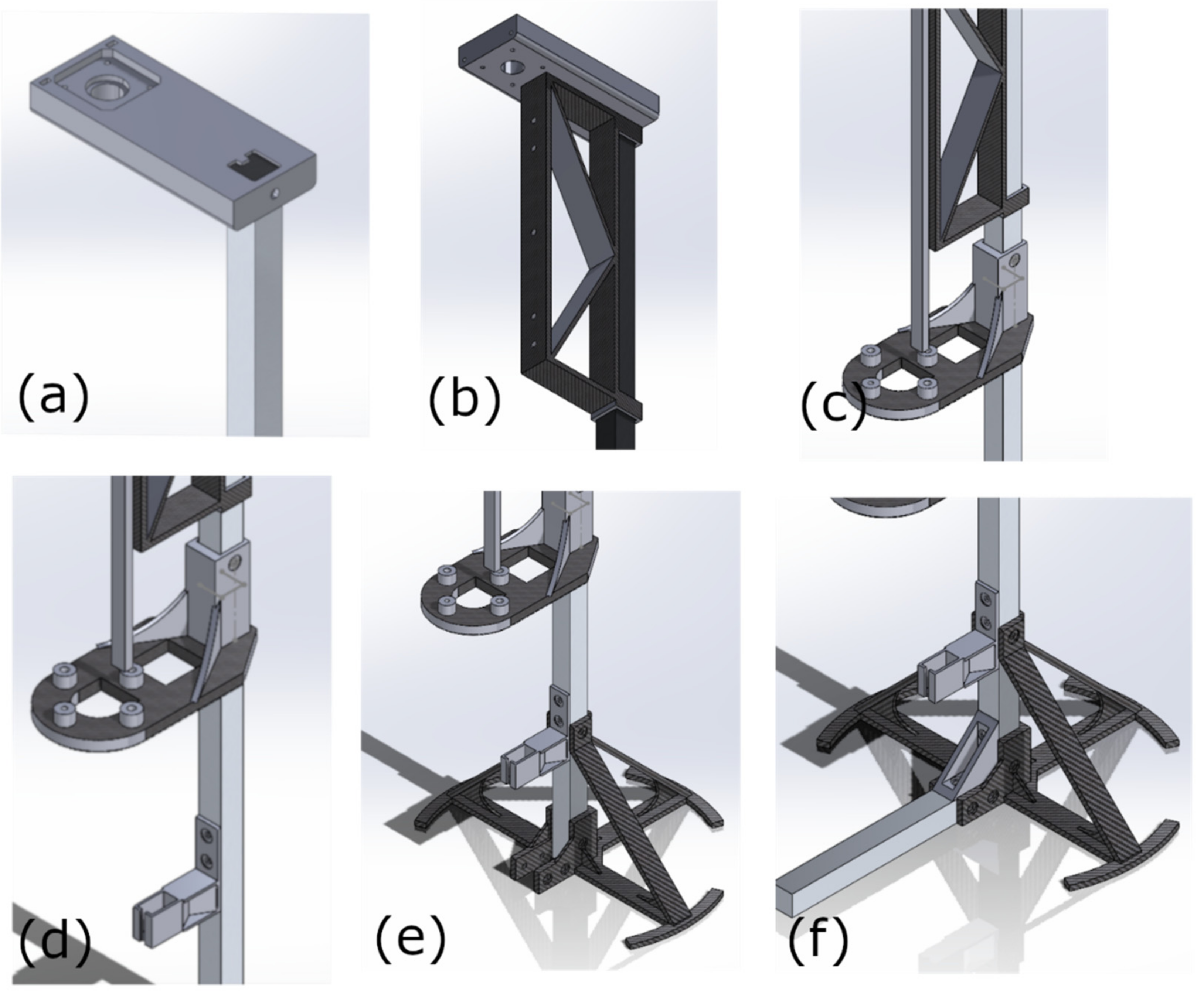
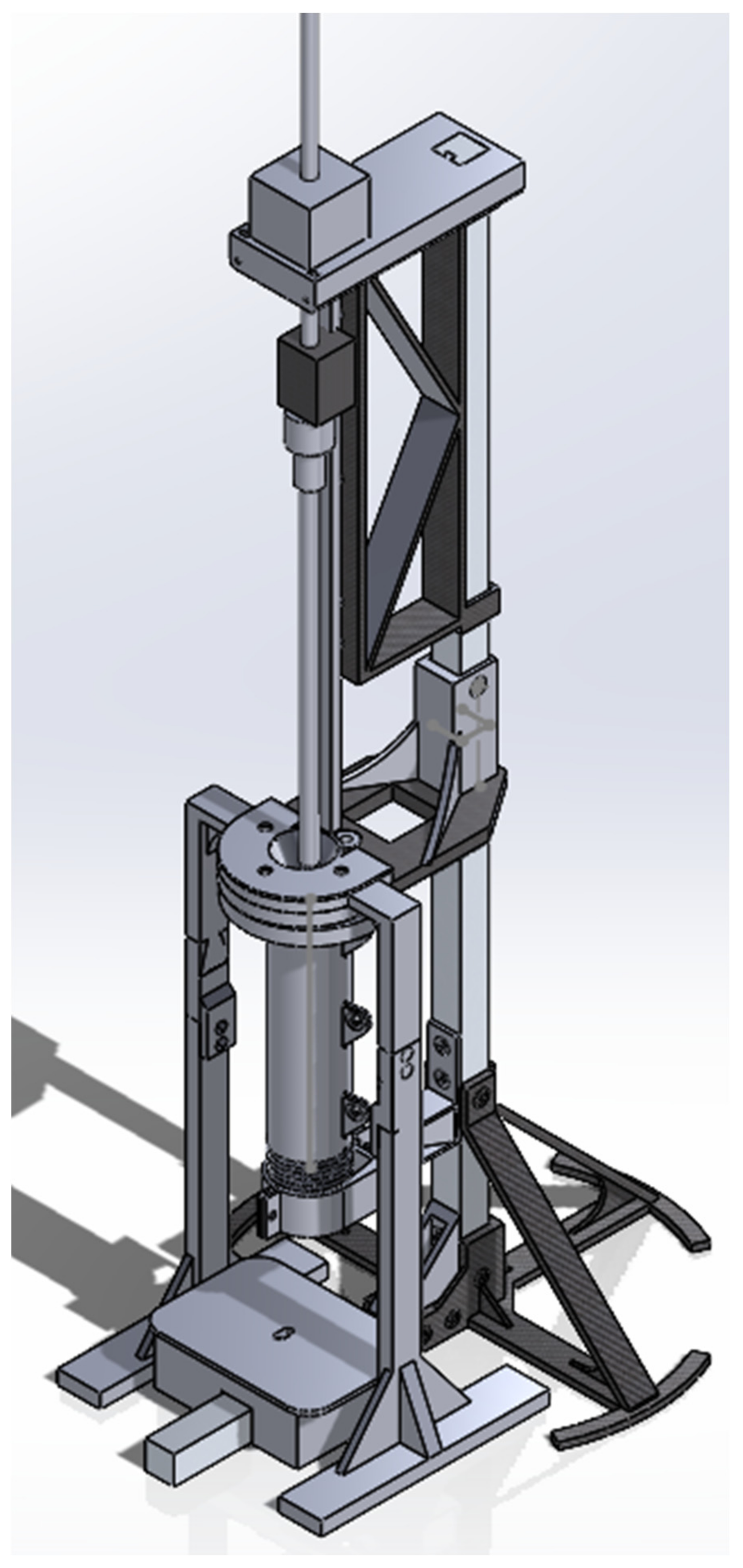
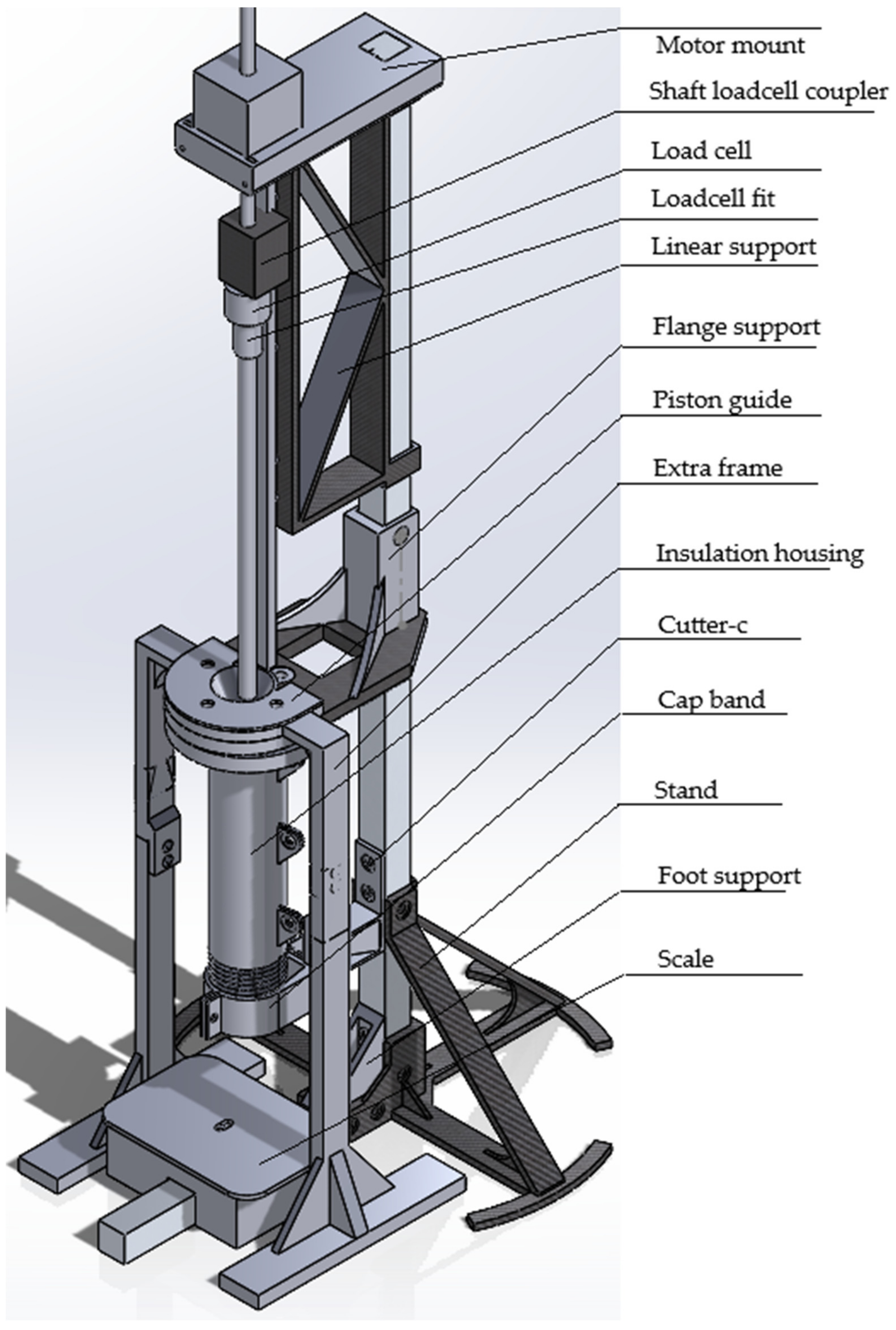
1.1.1. Step 1. Assemble the Frame
- Insert t-nut into the slot of the 1-meter aluminum profile, assemble 3D printed part motor mount on the top of the aluminum extrusion profile.
- Insert the same aluminum profile into the two holes of linear support.
- Push the linear support until it touches the motor support, then secure it to the aluminum extrusion profile with bolts and T-nuts. Attach the linear rail to the linear support with fasteners using the corresponding holes.
- Insert the aluminum profile into the 3D printed part Flange support and fix the position with bolts and t-nuts. The position depends on the length of the linear rail.
- Put the 3D printed part of the cutter connector in the right position and fix it with bolts and nuts. The position depends on the length of the heating pipe. It should allow the cutter to cut off the extrusions.
- Insert the aluminum extrusion profile into the 3D printed part Stand and fix it with fasteners.
- Attach another aluminum extrusion profile to the stand and fix the position with fasteners. Then assemble the 3D printed part foot support and make sure two aluminum extrusion profiles are vertical.
1.1.2. Step 2. Piston
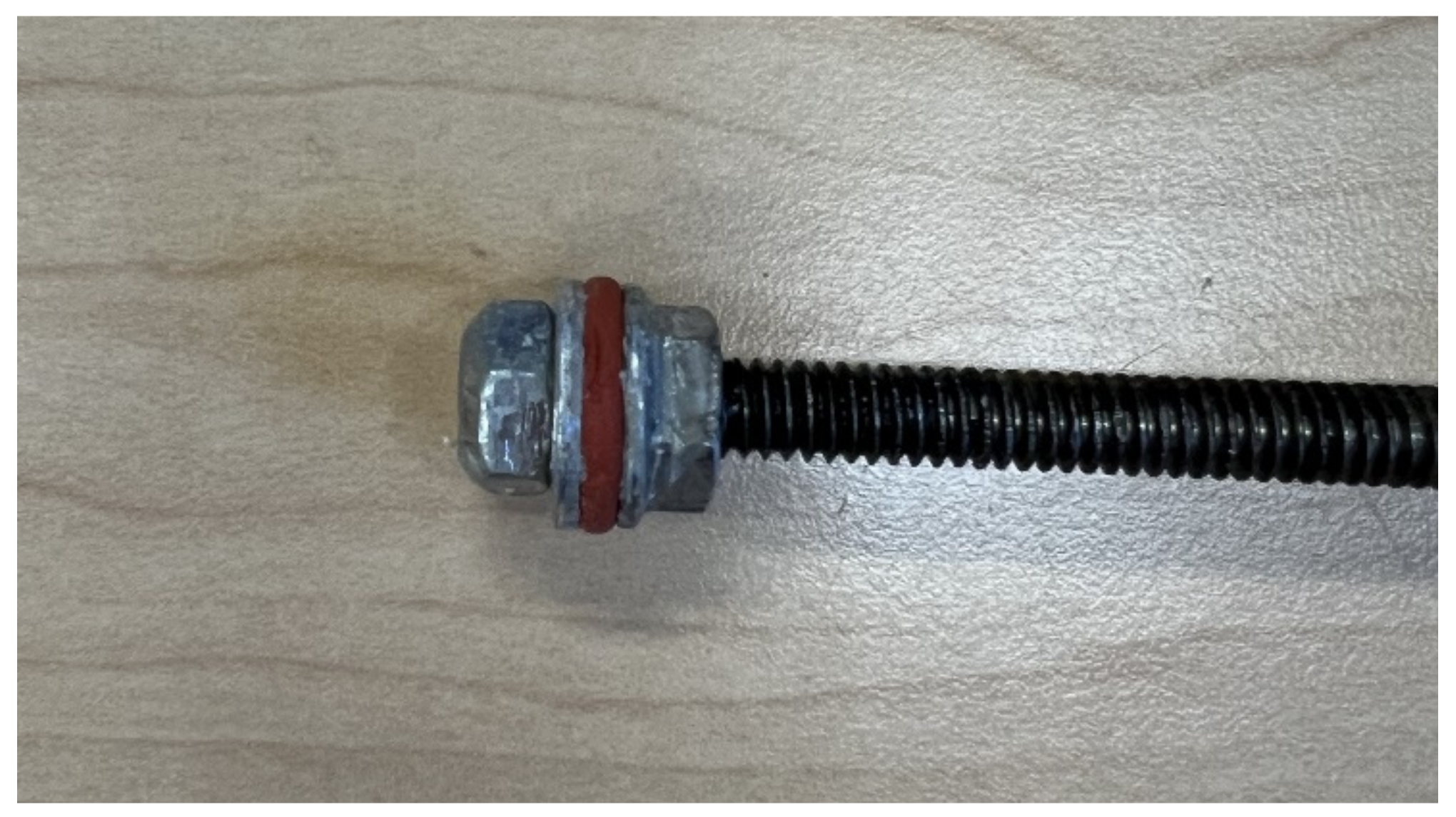
- Screw the ¼ inch serrated flange lock nut to the ¼-inch threaded rod and stop at 15mm away from the tip.
- Put an O-ring on top of the nut, then put a washer on top of it.
- Screw another self-lock nut, cover it with a piston guide, and ensure that all pieces have the same center point. Use the 3D printed part Piston tip guide to make sure all the components are centered and not too tight. If the screw is too tight, the O-ring in the middle will deform, which makes it harder to insert into the heating pipe.
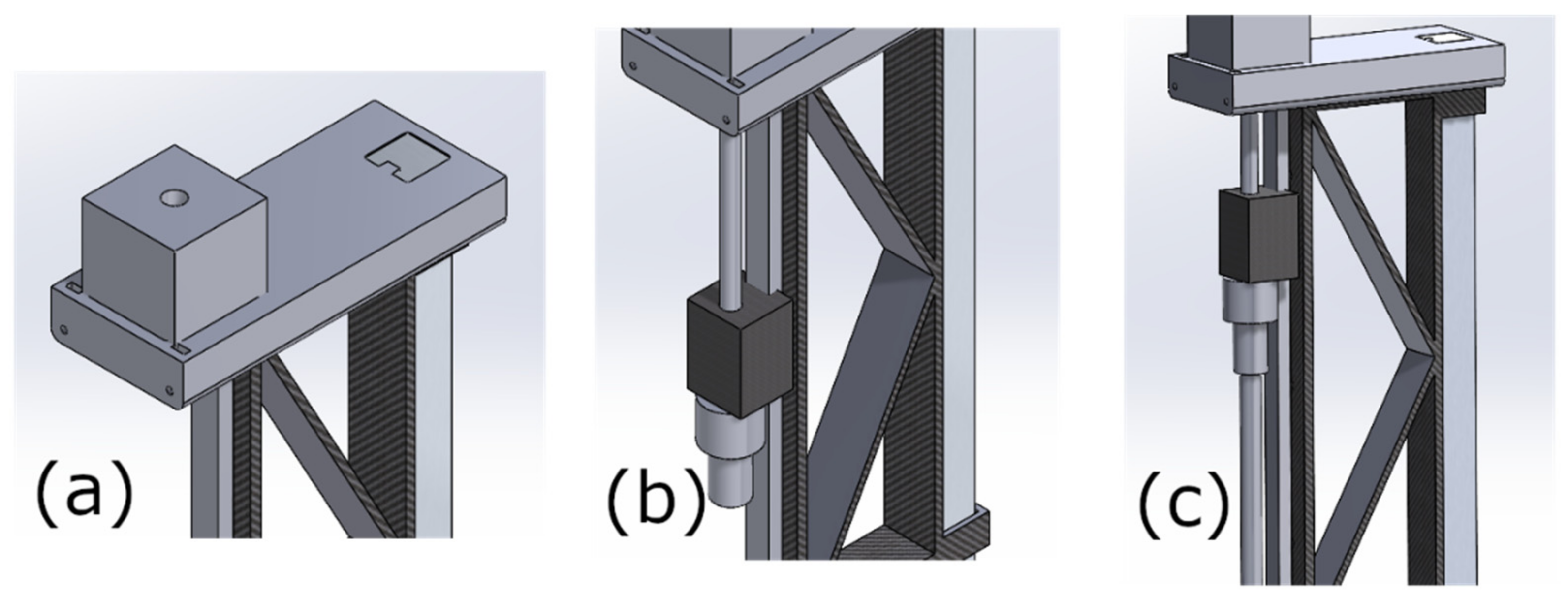
- Assemble the motor on the 3D printed part Motor Support.
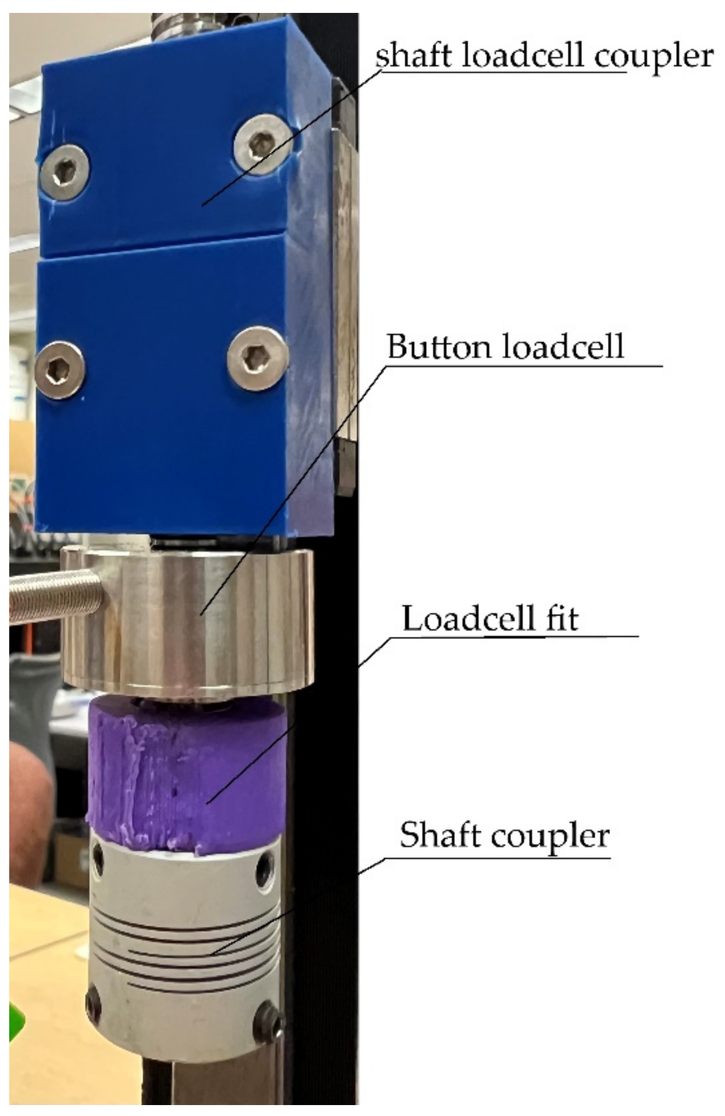
- Connect the shaft of the motor to the shaft loadcell coupler.
- Screw the Loadcell fit into the Shaft loadcell coupler, then install it on the slide block of the linear rail.
- Screw the insert nut into the 3D printed part loadcell fit, connect the loadcell fit and the button loadcell, then screw the button loadcell to the shaft loadcell coupler.
- Connect the shaft coupler to loadcell fit.
- Connect the piston rod with the shaft coupler.
1.1.3. Step 3. Heating Pipe
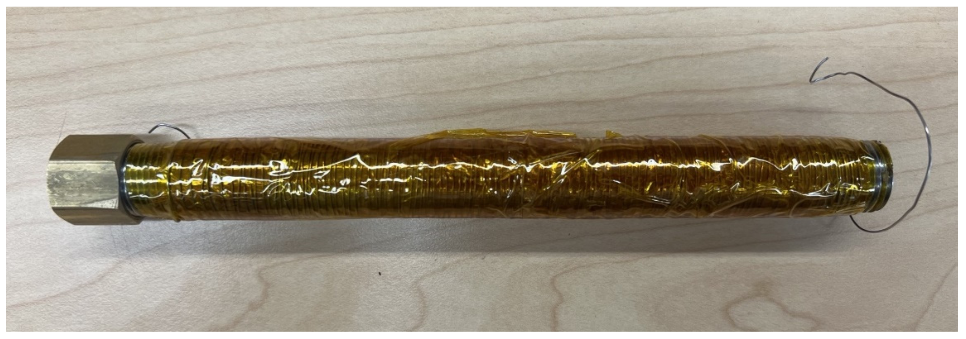
- Cover the whole pipe with high-temperature-resistant tape (Kapton Tape).
- Wind Nichrome wire around the iron pipe as required, ensuring the nichrome wire has sufficient resistance to at least meet the maximum current requirements of the relay. The nichrome wires must not touch each other to prevent short-circuiting or excessive heat generation at the contact points. After winding, wrap high-temperature tape around the outside of the resistance wire to achieve insulation.
- Tape the thermocouple to the outside of the resistance wire.
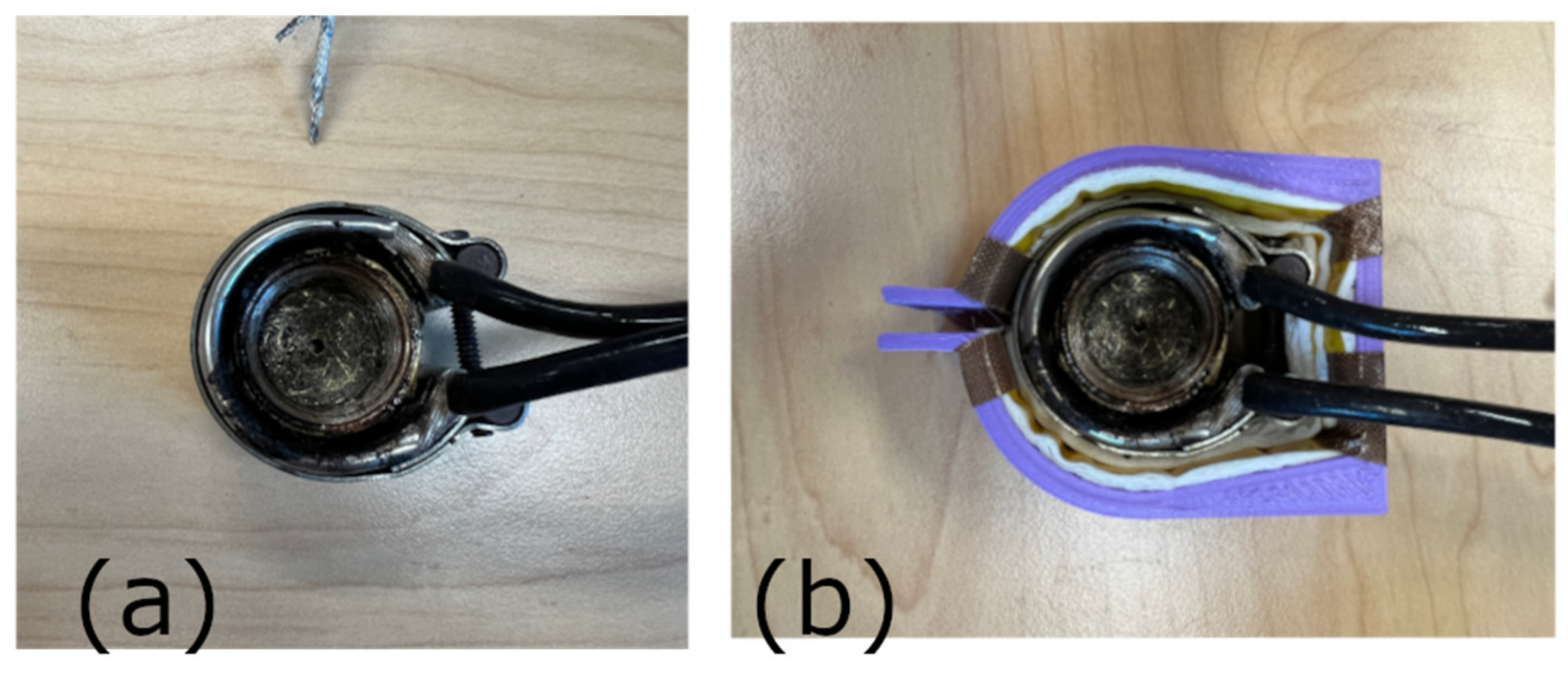
- Cover the pipe with heat insulation material, such as fiberglass. Cover the fiberglass layer with Kapton tape so that it can keep on the pipe.
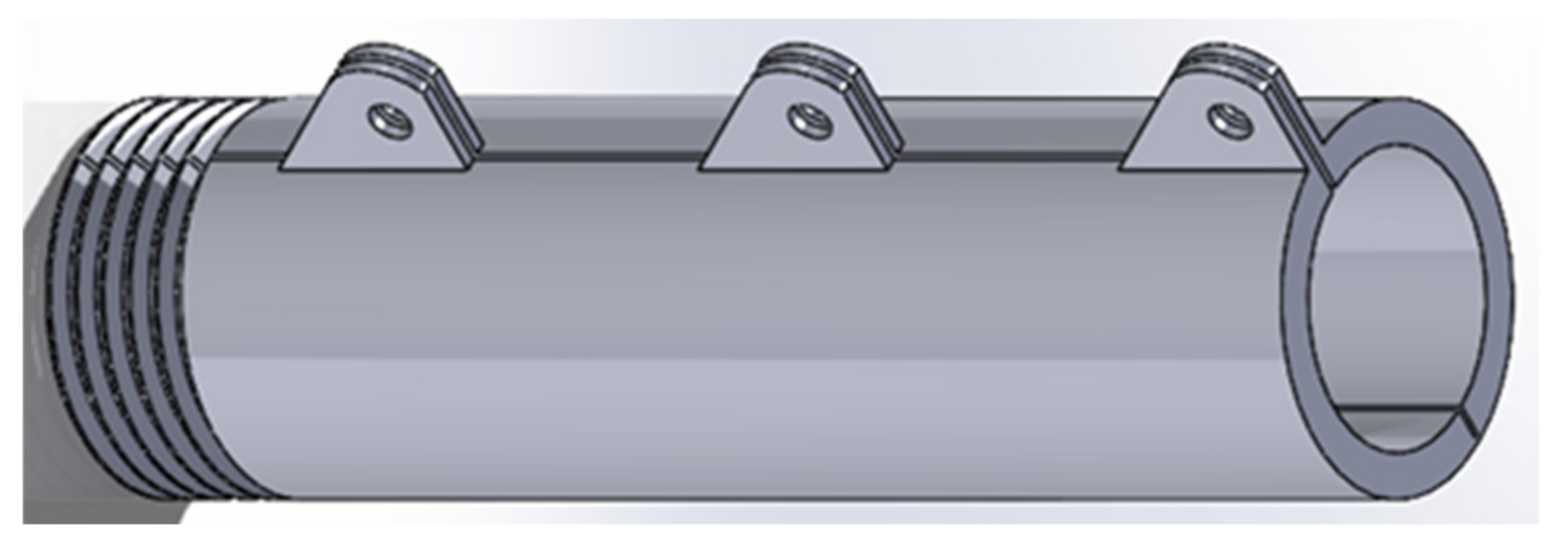
- Cover the insulation layer with 3D printed housing (insulation housing).
- Drill a 2 mm hole in the center of the cap.
- Insert the cap in the band heater.
- Tighten the screw on the band heater.
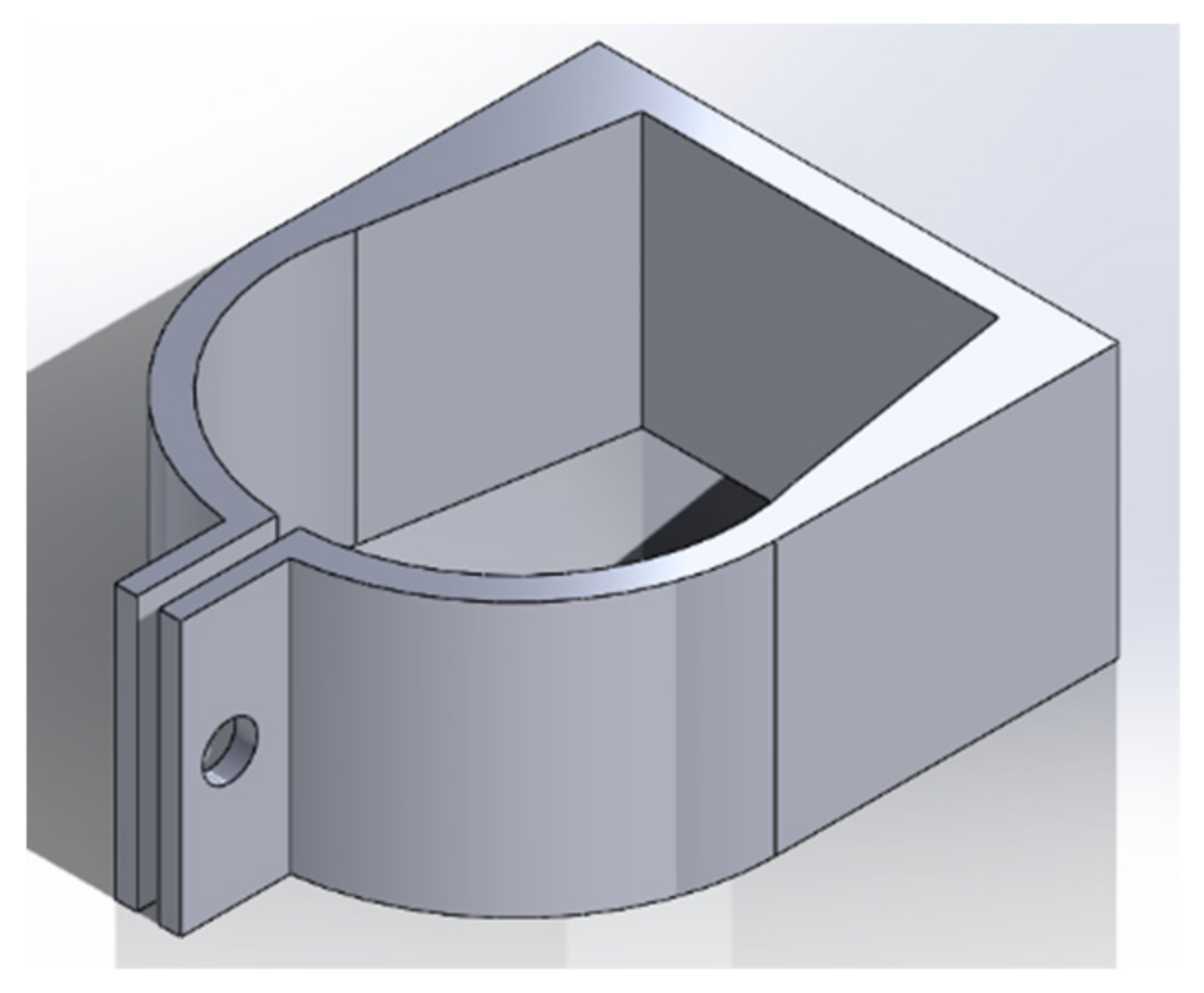
- Cover the band heater with a 3D printed insulation cap band.
- Screw the cap on one end of the pipe.
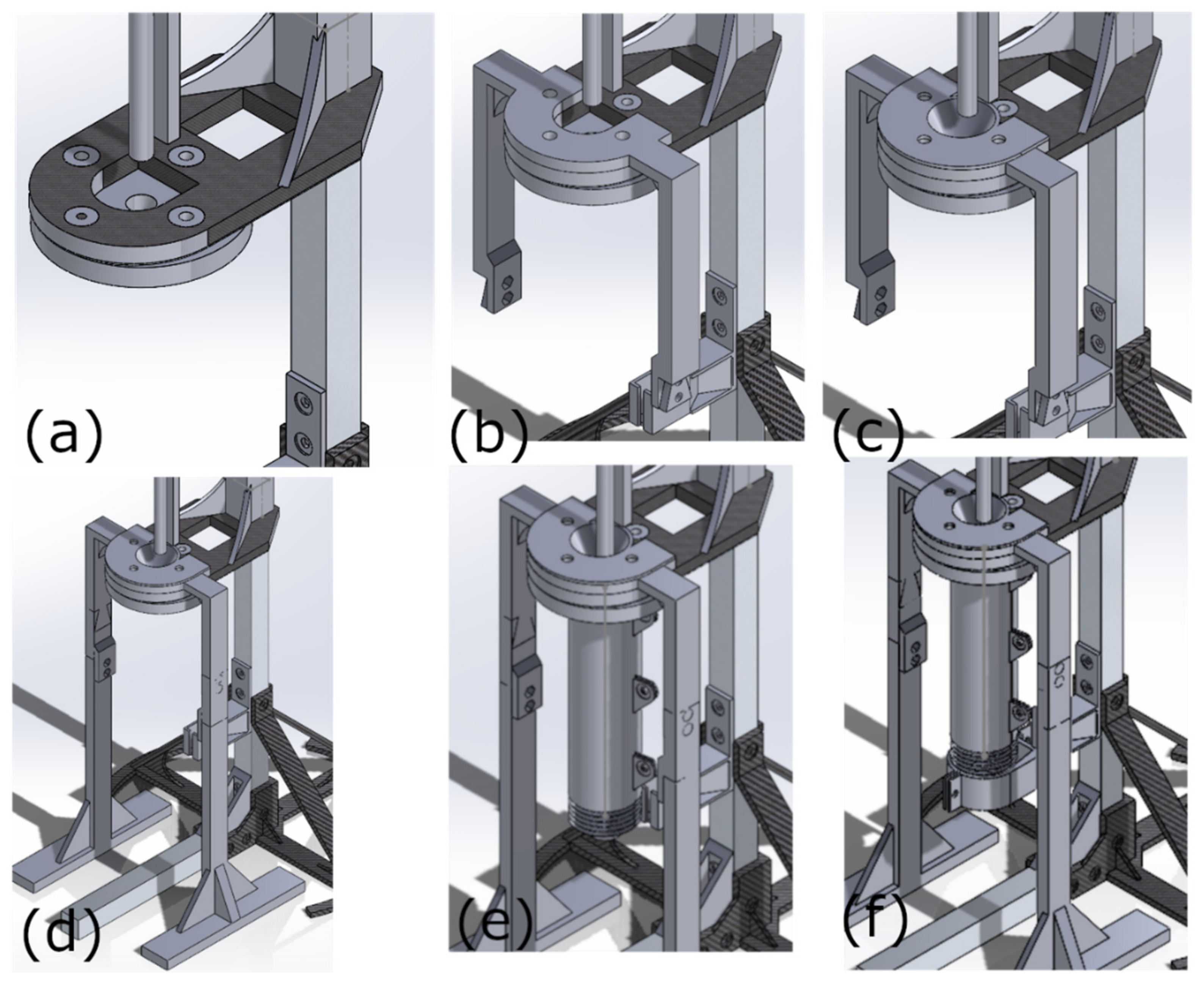
- Attach the flange and insulation pad to the 3D printed part of the flange support with bolts and nuts. The insulation pad should be between the flange and the flange support.
- Fix the extra frame and piston guide with the same bolts and nuts as the last step.
- Screw the pipe to the flange.
- Adjust the position of the blade. It should touch the bottom of the cap.
1.1.4. Step 4. Digital Scale
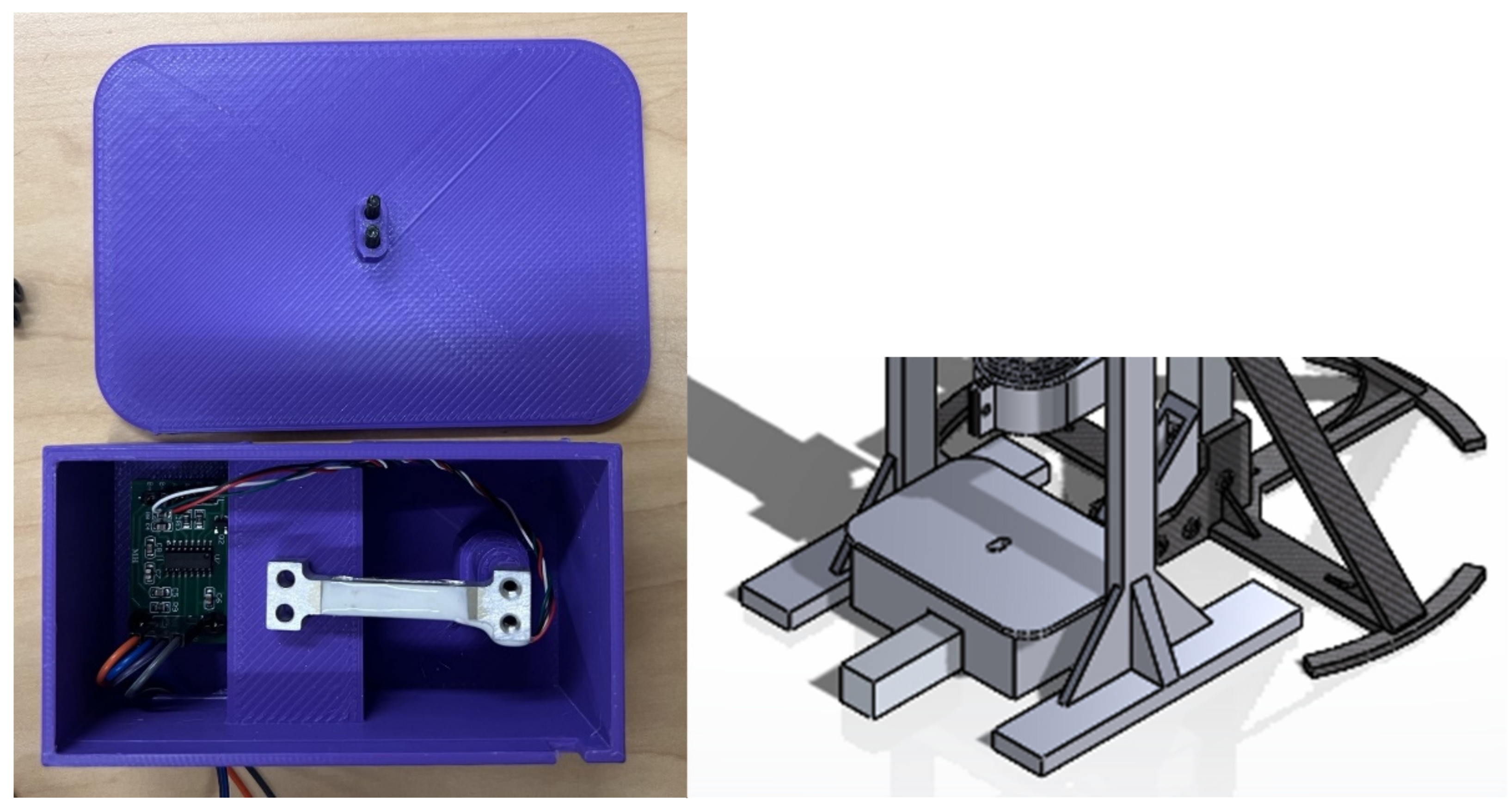
- Connect wires on the HX711 board.
- Assemble the scale platform on the load cell.
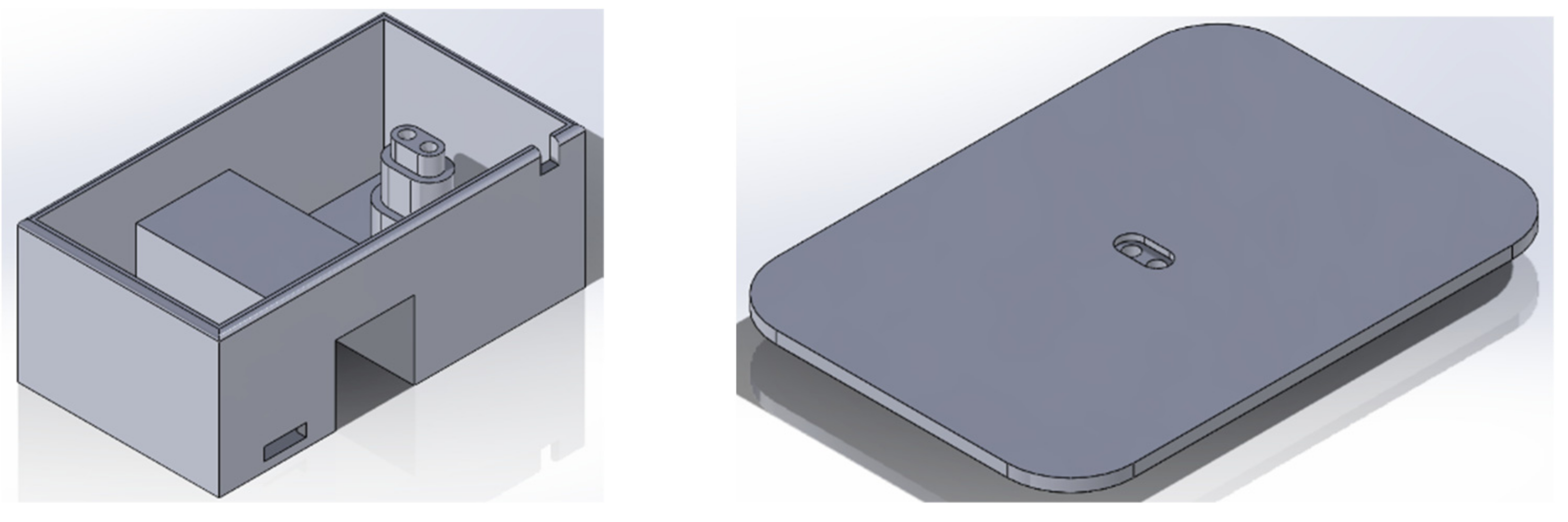
- Fix the HX711 board on the related slot in the scale housing.
- Assemble the load cell on the scale housing.
- Pull jump wires out and connect the other end to the main board.
1.2. Electronic
- Connect a high-temperature resistant connector to one end of the high-temperature resistant wire and connect it to the nichrome wire.
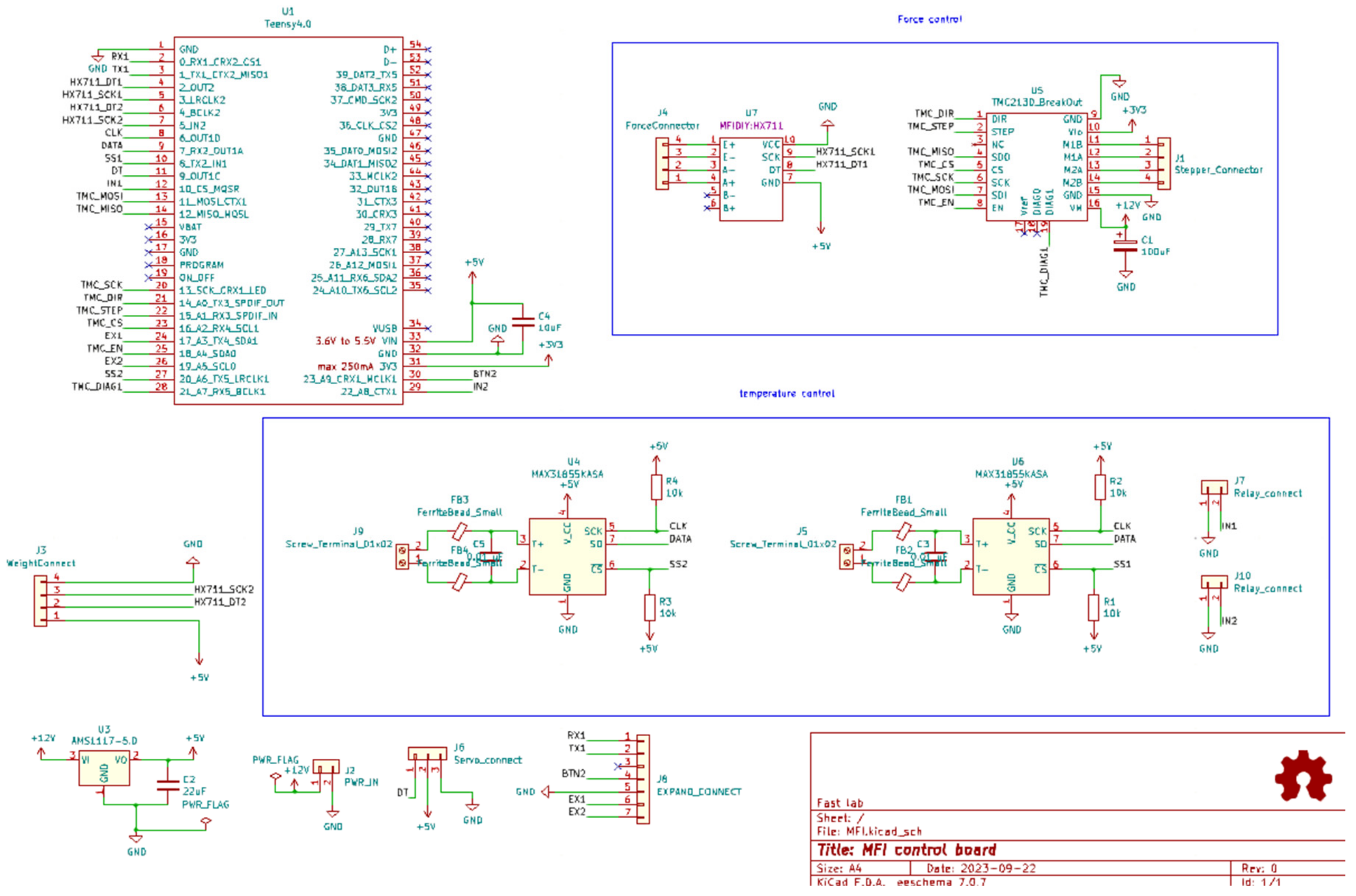
- Follow the instructions in the schematic in the Open Science Framework [77].
- Connect the Teensy board with the laptop.
- Plugin the power supply.
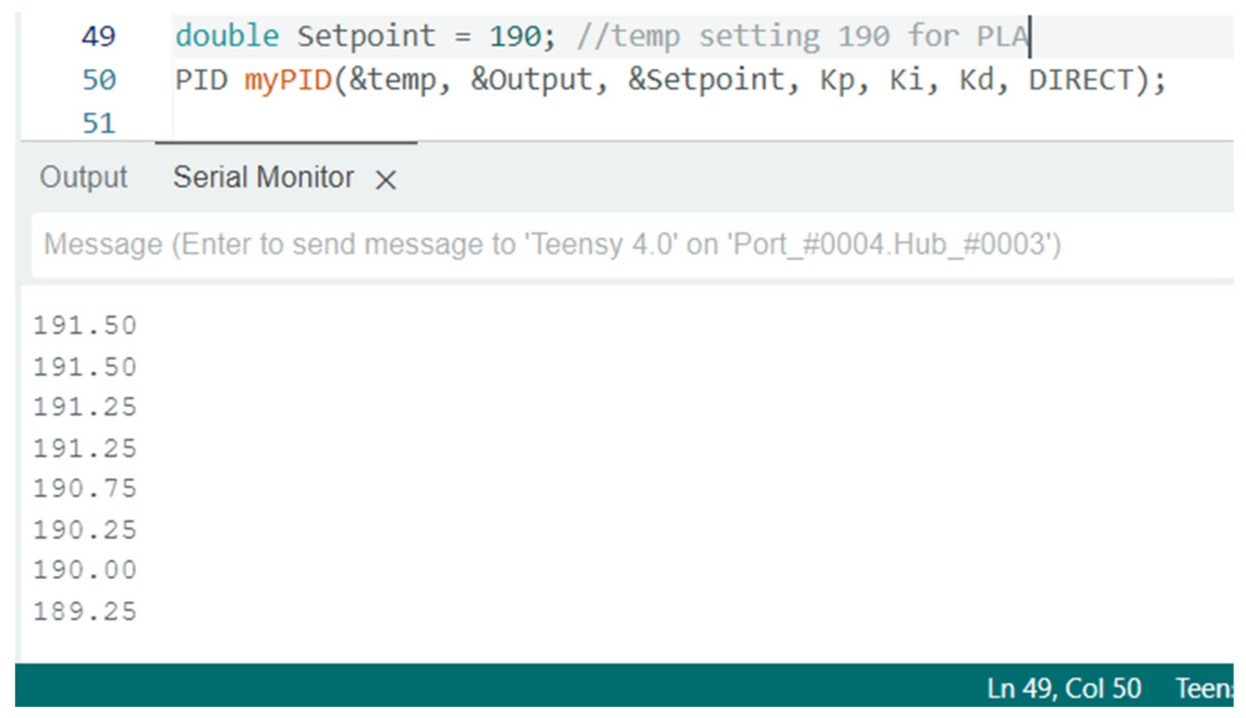
- Open the .io file with Arduino IDE and download all the libraries. Setup parameters are needed, and the new firmware is uploaded to the teensy board. More detailed instructions are in the code file.
- Open the Serial Monitor in Arduino IDE, baud rate 115200. “start” should show up in the Serial monitor.
- Input start command monitor “a “in Message blank. The temperature will increase, and the piston will start to go down automatically after the heating-up procedure ends.
- Fill in the samples when the temperature reaches the set point.
- Bring down the piston using the command “d”. The piston will start to go down automatically after the heating-up procedure ends.
- Wait for the pressure to get to the set point. Record the readings after the cutter cut-off samples.
- Clean up the barrel and the cap after the measurement is finished.

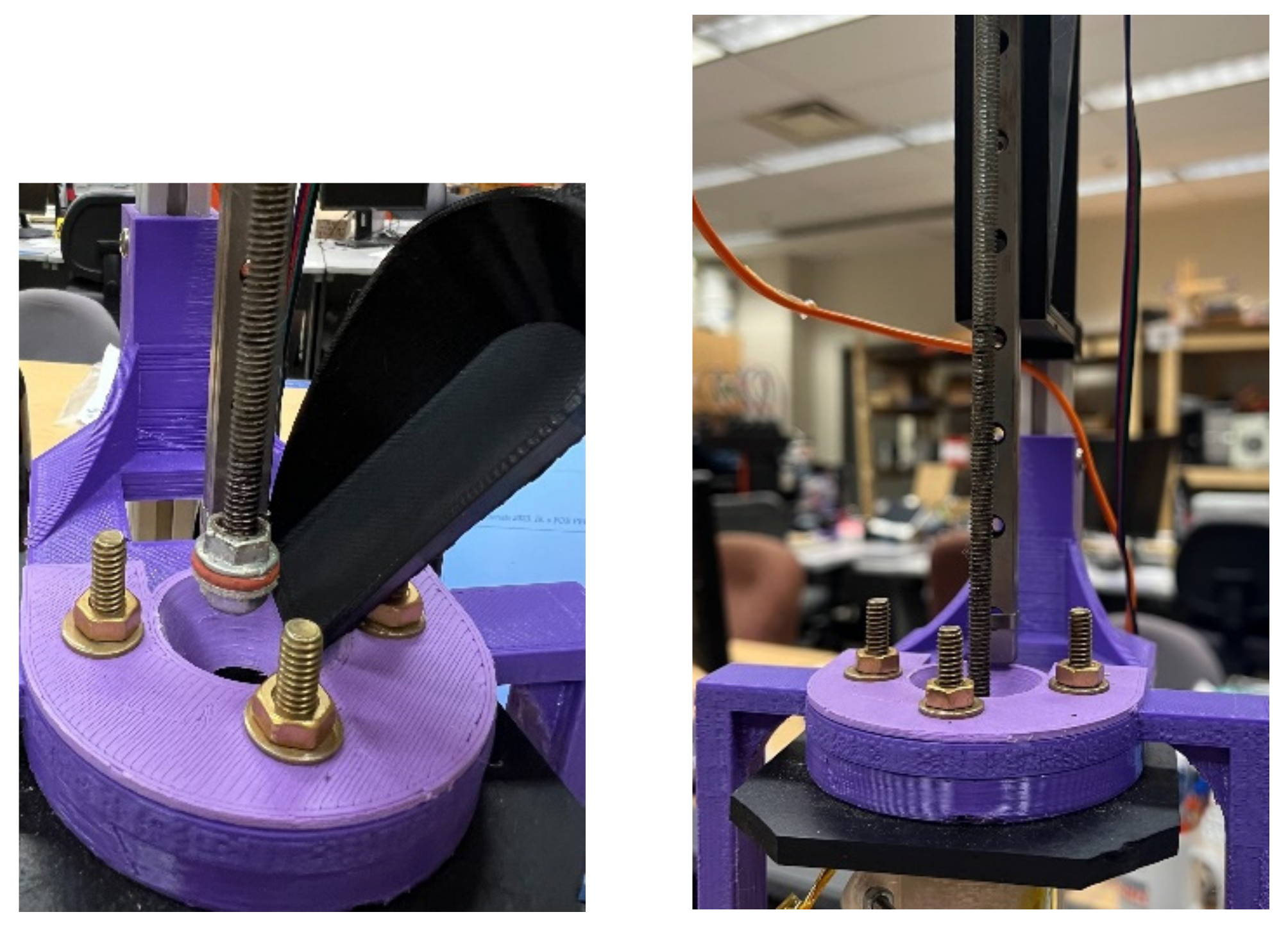
- Go into cleaning mode by inputting the command in the Arduino IDE serial monitor to keep the temperature.
- Dissemble the insulation band, unplug the band heater, and unscrew the cap with a clamp or heat-resistant gloves.
- Plug the band heater back and clean the cap with cleaning tools, such as a copper brush, etc.
- Pull out the piston and clean the piston tip with cleaning tools.
- Clean the tube with the piston and cover the piston tip with a cotton rug or robust paper.
- Screw the cap back after the cleaning process.
References
- Statista Research Department, “Global plastic production 1950-2021,” Statista. Available online: https://www.statista.com/statistics/282732/global-production-of-plastics-since-1950/ (accessed on 8 May 2023).
- G. Maitlo et al., “Plastic Waste Recycling, Applications, and Future Prospects for a Sustainable Environment,” Sustainability, vol. 14, no. 18, Art. no. 18, Jan. 2022. [CrossRef]
- A.L. Andrady, Ed., Plastics and the Environment, 1st ed. Wiley, 2003. [CrossRef]
- C.J. Moore, “Synthetic polymers in the marine environment: A rapidly increasing, long-term threat,” Environ. Res., vol. 108, no. 2, pp. 131–139, Oct. 2008. [CrossRef]
- S. Bejgarn, M. MacLeod, C. Bogdal, and M. Breitholtz, “Toxicity of leachate from weathering plastics: An exploratory screening study with Nitocra spinipes,” Chemosphere, vol. 132, pp. 114–119, Aug. 2015. [CrossRef]
- L. Bradney et al., “Particulate plastics as a vector for toxic trace-element uptake by aquatic and terrestrial organisms and human health risk,” Environ. Int., vol. 131, p. 104937, Oct. 2019. [CrossRef]
- F. M. Lamberti, L. A. Román-Ramírez, and J. Wood, “Recycling of Bioplastics: Routes and Benefits,” J. Polym. Environ., vol. 28, no. 10, pp. 2551–2571, Oct. 2020. [CrossRef]
- OECD Global Plastics Outlook Database, “Plastic pollution is growing relentlessly as waste management and recycling fall short, says OECD,” OECD. Available online: https://www.oecd.org/environment/plastic-pollution-is-growing-relentlessly-as-waste-management-and-recycling-fall-short.htm (accessed on 8 May 2023).
- S. C. Dertinger et al., “Technical pathways for distributed recycling of polymer composites for distributed manufacturing: Windshield wiper blades,” Resour. Conserv. Recycl., vol. 157, p. 104810, Jun. 2020. [CrossRef]
- S. Zhong and J. M. Pearce, “Tightening the loop on the circular economy: Coupled distributed recycling and manufacturing with recyclebot and RepRap 3-D printing,” Resour. Conserv. Recycl., vol. 128, pp. 48–58, Jan. 2018. [CrossRef]
- F. A. Cruz Sanchez, H. Boudaoud, M. Camargo, and J. M. Pearce, “Plastic recycling in additive manufacturing: A systematic literature review and opportunities for the circular economy,” J. Clean. Prod., vol. 264, p. 121602, Aug. 2020. [CrossRef]
- H. A. Little, N. G. Tanikella, M. J. Reich, M. J. Fiedler, S. L. Snabes, and J. M. Pearce, “Towards Distributed Recycling with Additive Manufacturing of PET Flake Feedstocks,” Materials, vol. 13, no. 19, p. 4273, Sep. 2020. [CrossRef]
- M. A. Kreiger, M. L. Mulder, A. G. Glover, and J. M. Pearce, “Life cycle analysis of distributed recycling of post-consumer high density polyethylene for 3-D printing filament,” J. Clean. Prod., vol. 70, pp. 90–96, May 2014. [CrossRef]
- M. Kreiger and J. M. Pearce, “Environmental Life Cycle Analysis of Distributed Three-Dimensional Printing and Conventional Manufacturing of Polymer Products,” ACS Sustain. Chem. Eng., vol. 1, no. 12, pp. 1511–1519, Dec. 2013. [CrossRef]
- J. Gwamuri, B. T. Wittbrodt, N. C. Anzalone, and J. M. Pearce, “Reversing the Trend of Large Scale and Centralization in Manufacturing: The Case of Distributed Manufacturing of Customizable 3-D-Printable Self-Adjustable Glasses,” Chall. Sustain., vol. 2, no. 1, pp. 30–40, Dec. 2014. [CrossRef]
- E. Petersen and J. Pearce, “Emergence of Home Manufacturing in the Developed World: Return on Investment for Open-Source 3-D Printers,” Technologies, vol. 5, no. 1, p. 7, Feb. 2017. [CrossRef]
- M. Mohammed, D. Wilson, E. Gomez-Kervin, A. Petsiuk, R. Dick, and J. M. Pearce, “Sustainability and feasibility assessment of distributed E-waste recycling using additive manufacturing in a Bi-continental context,” Addit. Manuf., vol. 50, p. 102548, Feb. 2022. [CrossRef]
- S. Zhong, P. Rakhe, and J. Pearce, “Energy Payback Time of a Solar Photovoltaic Powered Waste Plastic Recyclebot System,” Recycling, vol. 2, no. 2, p. 10, Jun. 2017. [CrossRef]
- P. Santander, F. A. Cruz Sanchez, H. Boudaoud, and M. Camargo, “Social, political, and technological dimensions of the sustainability evaluation of a recycling network. A literature review,” Clean. Eng. Technol., vol. 6, p. 100397, Feb. 2022. [CrossRef]
- P. Santander, F. A. Cruz Sanchez, H. Boudaoud, and M. Camargo, “Closed loop supply chain network for local and distributed plastic recycling for 3D printing: a MILP-based optimization approach,” Resour. Conserv. Recycl., vol. 154, p. 104531, Mar. 2020. [CrossRef]
- C. Caceres Mendoza, P. Santander, F. Cruz-Sanchez, N. Troussier, M. Camargo, and H. Boudaoud, “Life Cycle Assessment of Distributed Plastic Recycling Via Additive Manufacturing,” Sep. 26, 2022, Rochester, NY: 4230044. [CrossRef]
- A.O. Laplume, B. Petersen, and J. M. Pearce, “Global value chains from a 3D printing perspective,” J. Int. Bus. Stud., vol. 47, no. 5, pp. 595–609, Jun. 2016. [CrossRef]
- C. Baechler, M. DeVuono, and J. M. Pearce, “Distributed recycling of waste polymer into RepRap feedstock,” Rapid Prototyp. J., vol. 19, no. 2, pp. 118–125, Mar. 2013. [CrossRef]
- A.L. Woern, J. R. McCaslin, A. M. Pringle, and J. M. Pearce, “RepRapable Recyclebot: Open source 3-D printable extruder for converting plastic to 3-D printing filament,” HardwareX, vol. 4, p. e00026, Oct. 2018. [CrossRef]
- R. Jones et al., “RepRap – the replicating rapid prototyper,” Robotica, vol. 29, no. 1, pp. 177–191, Jan. 2011. [CrossRef]
- E. Sells, S. Bailard, Z. Smith, A. Bowyer, and V. Olliver, “RepRap: The Replicating Rapid Prototyper: Maximizing Customizability by Breeding the Means of Production,” in Handbook of Research in Mass Customization and Personalization, World Scientific Publishing Company, 2009, pp. 568–580. [CrossRef]
- A. Bowyer, “3D Printing and Humanity’s First Imperfect Replicator,” 3D Print. Addit. Manuf., vol. 1, no. 1, pp. 4–5, Mar. 2014. [CrossRef]
- F. Cruz Sanchez, S. Lanza, H. Boudaoud, S. Hoppe, and M. Camargo, “Polymer Recycling and Additive Manufacturing in an Open Source context : Optimization of processes and methods,” Aug. 2015.
- I. Anderson, “Mechanical Properties of Specimens 3D Printed with Virgin and Recycled Polylactic Acid,” 3D Print. Addit. Manuf., vol. 4, no. 2, pp. 110–115, Jun. 2017. [CrossRef]
- J. Pakkanen, D. Manfredi, P. Minetola, and L. Iuliano, “About the Use of Recycled or Biodegradable Filaments for Sustainability of 3D Printing,” Apr. 2017, pp. 776–785. [CrossRef]
- M. I. Mohammed, D. Wilson, E. Gomez-Kervin, C. Vidler, L. Rosson, and J. Long, “The Recycling of E-Waste ABS Plastics by Melt Extrusion and 3D Printing Using Solar Powered Devices as a Transformative Tool for Humanitarian Aid,” 2018. Available online: https://hdl.handle.net/2152/90080 (accessed on 11 March 2024).
- S. Chong, G.-T. Pan, M. Khalid, T. C.-K. Yang, S.-T. Hung, and C.-M. Huang, “Physical Characterization and Pre-assessment of Recycled High-Density Polyethylene as 3D Printing Material,” J. Polym. Environ., vol. 2, no. 25, pp. 136–145, Jul. 2016. [CrossRef]
- M. Pepi, N. Zander, and M. Gillan, “Towards Expeditionary Battlefield Manufacturing Using Recycled, Reclaimed, and Scrap Materials,” JOM, vol. 70, Jul. 2018. [CrossRef]
- N. Zander, M. Gillan, and R. Lambeth, “Recycled polyethylene terephthalate as a new FFF feedstock material,” Addit. Manuf., vol. 21, pp. 174–182, May 2018. [CrossRef]
- N. Zander, “Recycled Polymer Feedstocks for Material Extrusion Additive Manufacturing,” 2019, pp. 37–51. [CrossRef]
- K.R. Hart, J. B. Frketic, and J. R. Brown, “Recycling meal-ready-to-eat (MRE) pouches into polymer filament for material extrusion additive manufacturing,” Addit. Manuf., vol. 21, pp. 536–543, May 2018. [CrossRef]
- S. Oberloier, N. G. Whisman, and J. M. Pearce, “Finding Ideal Parameters for Recycled Material Fused Particle Fabrication-Based 3D Printing Using an Open Source Software Implementation of Particle Swarm Optimization,” 3D Print. Addit. Manuf., vol. 10, no. 6, pp. 1287–1300, Dec. 2023. [CrossRef]
- A.L. Woern and J. M. Pearce, “Distributed Manufacturing of Flexible Products: Technical Feasibility and Economic Viability,” Technologies, vol. 5, no. 4, Art. no. 4, Dec. 2017. [CrossRef]
- X. Tian, T. Liu, Q. Wang, A. Dilmurat, D. Li, and G. Ziegmann, “Recycling and remanufacturing of 3D printed continuous carbon fiber reinforced PLA composites,” J. Clean. Prod., vol. 142, pp. 1609–1618, Jan. 2017. [CrossRef]
- A. Pringle, M. Rudnicki, and J. Pearce, “Wood Furniture Waste-Based Recycled 3-D Printing Filament,” For. Prod. J., vol. 68, Nov. 2017. [CrossRef]
- P. Parandoush and D. Lin, “A review on additive manufacturing of polymer-fiber composites,” Compos. Struct., vol. 182, pp. 36–53, Dec. 2017. [CrossRef]
- B.P. Heller, D. E. Smith, and D. A. Jack, “Planar deposition flow modeling of fiber filled composites in large area additive manufacturing,” Addit. Manuf., vol. 25, pp. 227–238, Jan. 2019. [CrossRef]
- A. Romani, L. Perusin, M. Ciurnelli, and M. Levi, “Characterization of PLA feedstock after multiple recycling processes for large-format material extrusion additive manufacturing,” Mater. Today Sustain., vol. 25, p. 100636, Mar. 2024. [CrossRef]
- J. M. Justino Netto, H. T. Idogava, L. E. Frezzatto Santos, Z. de C. Silveira, P. Romio, and J. L. Alves, “Screw-assisted 3D printing with granulated materials: a systematic review,” Int. J. Adv. Manuf. Technol., vol. 115, no. 9, pp. 2711–2727, Aug. 2021. [CrossRef]
- M.J. Reich, A. L. Woern, N. G. Tanikella, and J. M. Pearce, “Mechanical Properties and Applications of Recycled Polycarbonate Particle Material Extrusion-Based Additive Manufacturing,” Materials, vol. 12, no. 10, Art. no. 10, Jan. 2019. [CrossRef]
- A. Romani, M. Levi, and J. M. Pearce, “Recycled polycarbonate and polycarbonate/acrylonitrile butadiene styrene feedstocks for circular economy product applications with fused granular fabrication-based additive manufacturing,” Sustain. Mater. Technol., vol. 38, p. e00730, Dec. 2023. [CrossRef]
- C. Suescun Gonzalez, F. A. Cruz Sanchez, H. Boudaoud, C. Nouvel, and J. M. Pearce, “Multi-material distributed recycling via material extrusion: recycled high density polyethylene and poly (ethylene terephthalate) mixture,” Polym. Eng. Sci., vol. 64, no. 4, pp. 1555–1570, 2024. [CrossRef]
- A. Alexandre, F. A. Cruz Sanchez, H. Boudaoud, M. Camargo, and J. M. Pearce, “Mechanical Properties of Direct Waste Printing of Polylactic Acid with Universal Pellets Extruder: Comparison to Fused Filament Fabrication on Open-Source Desktop Three-Dimensional Printers,” 3D Print. Addit. Manuf., vol. 7, no. 5, pp. 237–247, Oct. 2020. [CrossRef]
- A. Woern, D. Byard, R. Oakley, M. Fiedler, S. Snabes, and J. Pearce, “Fused Particle Fabrication 3-D Printing: Recycled Materials’ Optimization and Mechanical Properties,” Materials, vol. 11, no. 8, p. 1413, Aug. 2018. [CrossRef]
- S. Whyman, K. M. Arif, and J. Potgieter, “Design and development of an extrusion system for 3D printing biopolymer pellets,” Int. J. Adv. Manuf. Technol., vol. 96, no. 9, pp. 3417–3428, Jun. 2018. [CrossRef]
- M. Paramatti, A. Romani, G. Pugliese, and M. Levi, “PLA Feedstock Filled with Spent Coffee Grounds for New Product Applications with Large-Format Material Extrusion Additive Manufacturing,” ACS Omega, vol. 9, no. 6, pp. 6423–6431, Feb. 2024. [CrossRef]
- N. Volpato, D. Kretschek, J. A. Foggiatto, and C. M. Gomez da Silva Cruz, “Experimental analysis of an extrusion system for additive manufacturing based on polymer pellets,” Int. J. Adv. Manuf. Technol., vol. 81, no. 9, pp. 1519–1531, Dec. 2015. [CrossRef]
- D. Byard, A. Woern, R. Oakley, M. Fiedler, S. Snabes, and J. Pearce, “Green fab lab applications of large-area waste polymer-based additive manufacturing,” Addit. Manuf., vol. 27, pp. 515–525, May 2019. [CrossRef]
- W. d’Ambrières, “Plastics recycling worldwide: current overview and desirable changes,” Field Actions Sci. Rep. J. Field Actions, no. Special Issue 19, Art. no. Special Issue 19, Mar. 2019.
- B. Ruj, V. Pandey, P. Jash, and V. Srivastava, “Sorting of plastic waste for effective recycling,” Int J Appl Sci Eng Res, vol. 4, Jan. 2015. [CrossRef]
- S. Wang, L. Capoen, D. R. D’hooge, and L. Cardon, “Can the melt flow index be used to predict the success of fused deposition modelling of commercial poly(lactic acid) filaments into 3D printed materials?,” Plast. Rubber Compos., Feb. 2018. Available online: https://journals.sagepub.com/doi/full/10.1080/14658011.2017.1397308 (accessed on 16 July 2024).
- M. Spoerk, J. Gonzalez-Gutierrez, J. Sapkota, S. Schuschnigg, and C. Holzer, “Effect of the printing bed temperature on the adhesion of parts produced by fused filament fabrication,” Plast. Rubber Compos., vol. 47, no. 1, pp. 17–24, Feb. 2018. [CrossRef]
- S. Guerreiro, I. João, and L. Pimentel Real, “Evaluation of the influence of testing parameters on the melt flow index of thermoplastics,” Polym. Test., vol. 31, pp. 1026–1030, Dec. 2012. [CrossRef]
- M. Teresa Rodríguez-Hernández, J. L. Angulo-Sánchez, and A. Pérez-Chantaco, “Determination of the molecular characteristics of commercial polyethylenes with different architectures and the relation with the melt flow index,” J. Appl. Polym. Sci., vol. 104, no. 3, pp. 1572–1578, 2007. [CrossRef]
- A.V. Shenoy and D. R. Saini, “Melt flow index: More than just a quality control rheological parameter. Part I,” Adv. Polym. Technol., vol. 6, no. 1, pp. 1–58, 1986. [CrossRef]
- R. V. Pazhamannil, J. N. V. N., G. P., and A. Edacherian, “Property enhancement approaches of fused filament fabrication technology: A review,” Polym. Eng. Sci., vol. 62, no. 5, pp. 1356–1376, 2022. [CrossRef]
- E.E. Ferg and L. L. Bolo, “A correlation between the variable melt flow index and the molecular mass distribution of virgin and recycled polypropylene used in the manufacturing of battery cases,” Polym. Test., vol. 32, no. 8, pp. 1452–1459, Dec. 2013. [CrossRef]
- B. Singh et al., “Investigations on Melt Flow Rate and Tensile Behaviour of Single, Double and Triple-Sized Copper Reinforced Thermoplastic Composites,” Materials, vol. 14, no. 13, Art. no. 13, Jan. 2021. [CrossRef]
- R. Plavec et al., “Influence of Multiple Thermomechanical Processing of 3D Filaments Based on Polylactic Acid and Polyhydroxybutyrate on Their Rheological and Utility Properties,” Polymers, vol. 14, no. 10, Art. no. 10, Jan. 2022. [CrossRef]
- N. Sa’ude, K. Kamarudin, M. Ibrahim, and M. H. I. Ibrahim, “Melt Flow Index of Recycle ABS for Fused Deposition Modeling (FDM) Filament,” Appl. Mech. Mater., vol. 773–774, pp. 3–7, 2015. [CrossRef]
- F. Laoutid, S. Lafqir, A. Toncheva, and P. Dubois, “Valorization of Recycled Tire Rubber for 3D Printing of ABS- and TPO-Based Composites,” Materials, vol. 14, no. 19, Art. no. 19, Jan. 2021. [CrossRef]
- M. Garwacki, I. Cudnik, D. Dziadowiec, P. Szymczak, and J. Andrzejewski, “The Development of Sustainable Polyethylene Terephthalate Glycol-Based (PETG) Blends for Additive Manufacturing Processing—The Use of Multilayered Foil Waste as the Blend Component,” Materials, vol. 17, no. 5, Art. no. 5, Jan. 2024. [CrossRef]
- A. Gupta, M. Misra, and A. K. Mohanty, “Novel sustainable materials from waste plastics: compatibilized blend from discarded bale wrap and plastic bottles,” RSC Adv., vol. 11, no. 15, pp. 8594–8605, Feb. 2021. [CrossRef]
- V. Kumar, R. Singh, and I. P. S. Ahuja, “On correlation of rheological, thermal, mechanical and morphological properties of chemical assisted mechanically blended ABS-Graphene composite as tertiary recycling for 3D printing applications,” Adv. Mater. Process. Technol., Jul. 2022. Available online: https://www.tandfonline.com/doi/abs/10.1080/2374068X.2021.1913324 (accessed on 22 July 2024).
- E.O. Cisneros-López et al., “Recycled poly(lactic acid)–based 3D printed sustainable biocomposites: a comparative study with injection molding,” Mater. Today Sustain., vol. 7–8, p. 100027, Mar. 2020. [CrossRef]
- O. Zabihi et al., “Mechanical upcycling of single-use face mask waste into high-performance composites: An ecofriendly approach with cost-benefit analysis,” Sci. Total Environ., vol. 919, p. 170469, Apr. 2024. [CrossRef]
- V. Mishra, C. K. Ror, S. Negi, S. Kar, and L. N. Borah, “Development of sustainable 3D printing filaments using recycled/virgin ABS blends: Processing and characterization,” Polym. Eng. Sci., vol. 63, no. 7, pp. 1890–1899, 2023. [CrossRef]
- I. Turku, S. Kasala, and T. Kärki, “Characterization of Polystyrene Wastes as Potential Extruded Feedstock Filament for 3D Printing,” Recycling, vol. 3, no. 4, Art. no. 4, Dec. 2018. [CrossRef]
- MXBAOHENG XNR-400B Melt Flow Rate Index Tester MFR Melt Flow Indexer Printing Machine (220V) : Amazon.ca: Tools & Home Improvement. Available online: https://www.amazon.ca/MXBAOHENG-XNR-400B-Indexer-Printing-Machine/dp/B07CMN9SWN?th=1 (accessed on 17 July 2024).
- Wholesale melt flow index mfi testing machine To Test Electronic Equipment - Alibaba.com. Available online: https://www.alibaba.com/showroom/melt-flow-index-mfi-testing-machine.html (accessed on 15 March 2024).
- MELT FLOW INDEXER-tabletop instrument that tests the melt mass. Available online: https://www.mrclab.com/melt-flow-indexer-1 (accessed on 15 March 2024).
- D. Liu and A. Romani, “MFI,” Jun. 2023. Available online: https://osf.io/68hbj/ (accessed on 24 July 2024).
- Teensy® 4.0. Available online: https://www.pjrc.com/store/teensy40.html (accessed on 11 March 2024).
- V. Klar, J. M. Pearce, P. Kärki, and P. Kuosmanen, “Ystruder: Open source multifunction extruder with sensing and monitoring capabilities,” HardwareX, vol. 6, p. e00080, Oct. 2019. [CrossRef]
- 14:00-17:00, “ISO 1133-1:2022,” ISO. Available online: https://www.iso.org/standard/83905.html (accessed on 16 July 2024).
- compass. Available online: https://compass.astm.org/document/?contentCode=ASTM%7CD1238-10%7Cen-US&proxycl=https%3A%2F%2Fsecure.astm.org&fromLogin=true (accessed on 16 July 2024).
- M. Y. T. Wu, S. L. Mak, W. F. Tang, C. H. Li, and T. W. Chan, “A Review on Melt Flow Index Characteristics of Polylactide (PLA) for Recycle Use in 3-D Printing,” J. Test. Eval., vol. 50, no. 4, pp. 2260–2267, 2022. [CrossRef]
- M. H. M. Nasir, M. M. Taha, N. Razali, R. A. Ilyas, V. F. Knight, and M. N. F. Norrrahim, “Effect of Chemical Treatment of Sugar Palm Fibre on Rheological and Thermal Properties of the PLA Composites Filament for FDM 3D Printing,” Materials, vol. 15, no. 22, Art. no. 22, Jan. 2022. [CrossRef]
- F. Doronin, A. Rudakova, G. Rytikov, and V. Nazarov, “A novel determination of the melt flow index of composite filaments used in extrusion additive manufacturing,” Polym. Test., vol. 133, p. 108376, Apr. 2024. [CrossRef]
- V. K n, D. Bonthu, M. Doddamani, and F. Pati, “Additive Manufacturing of Short Silk Fiber Reinforced PETG Composites,” Mater. Today Commun., vol. 33, p. 104772, Dec. 2022. [CrossRef]
- S. V. Kotomin, D. V. Kramarev, I. M. Obidin, and S. V. Polunin, “Influence of 3D Printing Conditions of Polyethylene Terephthalate Glycol on the Mechanical Properties of Products Based on It,” Polym. Sci. Ser. A, vol. 64, no. 6, pp. 617–623, Dec. 2022. [CrossRef]
- R. Singh et al., “On 3D printing of low-cost sensors using recycled PET,” Sādhanā, vol. 47, no. 4, p. 260, Nov. 2022. [CrossRef]
- PolyLite_PETG_TDS_V5.2.pdf. Available online: https://cdn.shopify.com/s/files/1/0548/7299/7945/files/PolyLite_PETG_TDS_V5.2.pdf?v=1640828798 (accessed on 24 July 2024).
- M. Bustos Seibert, G. A. Mazzei Capote, M. Gruber, W. Volk, and T. A. Osswald, “Manufacturing of a PET Filament from Recycled Material for Material Extrusion (MEX),” Recycling, vol. 7, no. 5, Art. no. 5, Oct. 2022. [CrossRef]
- M. Nofar and H. Oğuz, “Development of PBT/Recycled-PET Blends and the Influence of Using Chain Extender,” J. Polym. Environ., vol. 27, no. 7, pp. 1404–1417, Jul. 2019. [CrossRef]
- Ingeo Biopolymer 4043D Technical Data Sheet.
- M. Seifali Abbas-Abadi, M. Nekoomanesh Haghighi, H. Yeganeh, and B. Bozorgi, “The effect of melt flow index, melt flow rate, and particle size on the thermal degradation of commercial high density polyethylene powder,” J. Therm. Anal. Calorim., vol. 114, no. 3, pp. 1333–1339, Dec. 2013. [CrossRef]
- S.S. Bafna and A.-M. Beall, A Design of Experiments Study on the Factors Affecting Variability in the Melt Index Measurement.
- A. Shenoy and D. Saini, “Melt flow index: More than just a quality control rheological parameter. Part II,” Adv. Polym. Technol. - ADV POLYM TECHNOL, vol. 6, pp. 125–145, Jun. 1986. [CrossRef]
- S.K. Suman and V. K. Giri, “Speed control of DC motor using optimization techniques based PID Controller,” in 2016 IEEE International Conference on Engineering and Technology (ICETECH), Coimbatore, India: IEEE, Mar. 2016, pp. 581–587. [CrossRef]

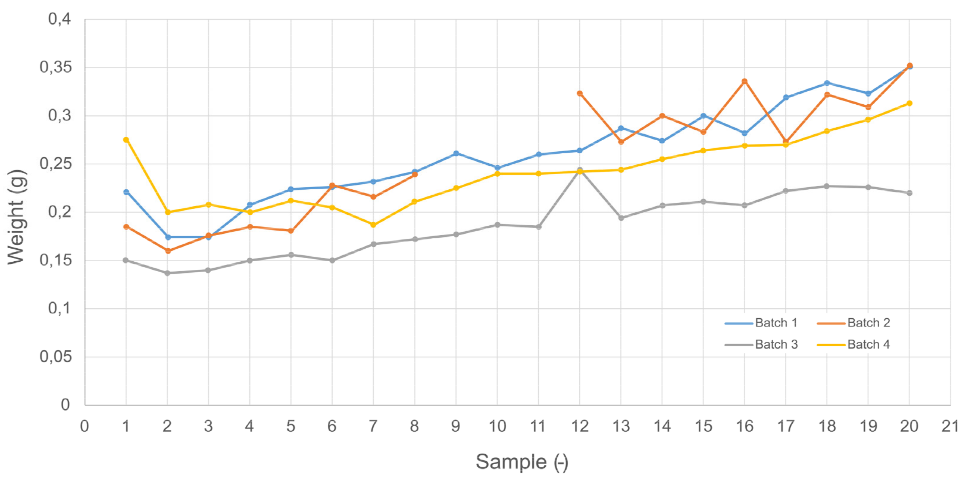
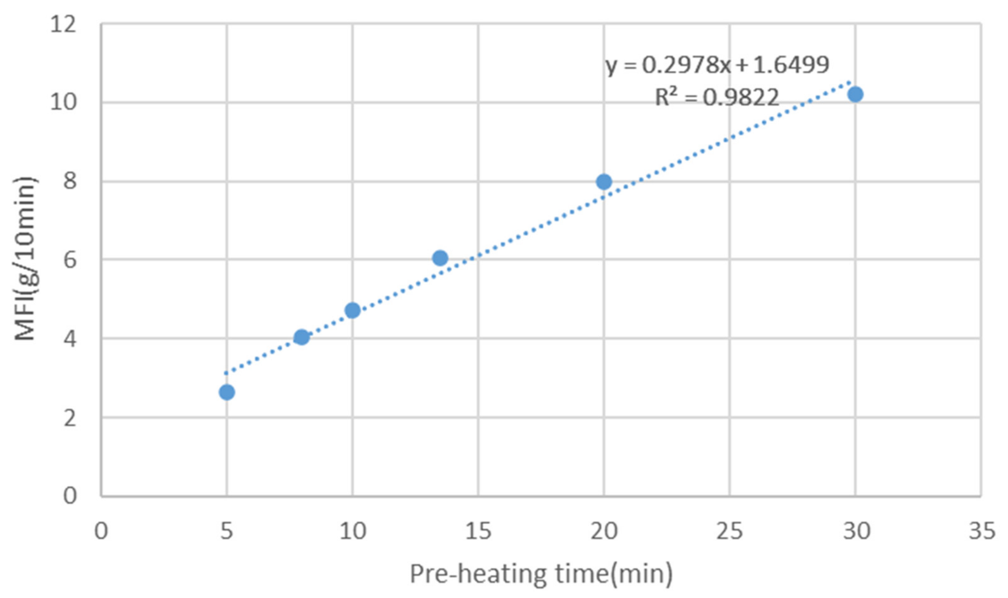
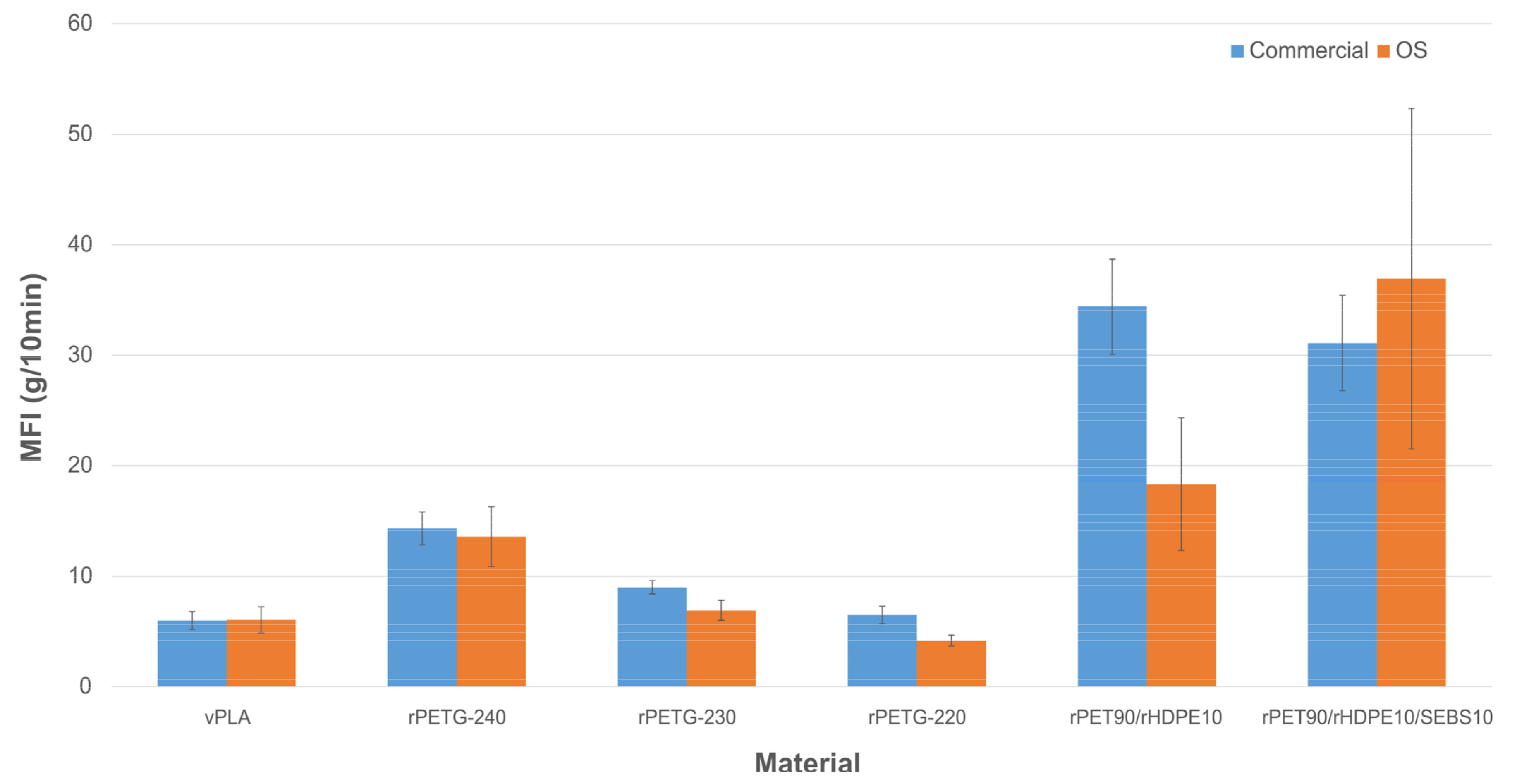
| Material | Weight (g) | Preheat time (s) | Temperature (C°) | MFI (g/10min) | ||||
|---|---|---|---|---|---|---|---|---|
| Commercial | OS | Commercial | OS | Datasheet | Commercial | OS | ||
| vPLA | 5 | 10 | 300 | 600 | 190 | 6.0 [91] | 6.0 ± 0.8 | 5.1 ± 0.3 |
| 5 | 10 | 300 | 810 | 190 | 6.0 | 6.0 ± 0.8 | 6.0 ± 1.2 | |
| rPETG | 5 | 10 | 300 | 600 | 240 | 10.8 [88] | 14. 3± 1.5 | 13.6 ± 2.7 |
| 5 | 10 | 300 | 600 | 230 | - | 9.0 ± 0.6 | 6.9 ± 0.9 | |
| 5 | 10 | 300 | 600 | 220 | 3.9 | 6.5 ± 0.8 | 4.2±0.5 | |
| rPET90/rHDPE10 | 5 | 10 | 300 | 600 | 255 | - | 34.5 ± 4.3 | 18.3 ± 6.0 |
| rPET90/rHDPE10/SEBS10 | 5 | 10 | 300 | 600 | 255 | - | 31.1 ± 4.3 | 36.9 ± 15.4 |
Disclaimer/Publisher’s Note: The statements, opinions and data contained in all publications are solely those of the individual author(s) and contributor(s) and not of MDPI and/or the editor(s). MDPI and/or the editor(s) disclaim responsibility for any injury to people or property resulting from any ideas, methods, instructions or products referred to in the content. |
© 2024 by the authors. Licensee MDPI, Basel, Switzerland. This article is an open access article distributed under the terms and conditions of the Creative Commons Attribution (CC BY) license (http://creativecommons.org/licenses/by/4.0/).


