Submitted:
28 September 2024
Posted:
30 September 2024
You are already at the latest version
Abstract
The position accuracy of polishing tool affects the surface quality of the polished aspheric surface. The contact deformation among the polishing tool, abrasives and aspheric part can cause a displacement, in turn will cause a position error of polishing tool, this will lead to a significant change of the polishing force. In order to resolve this error, this paper proposed a method of normal displacement compensation for NC polishing system by controlling the polishing force. Firstly, the coupling principle between polishing force and position of polishing tool are expounded, the relationship between normal displacement and deformation is analyzed, based on Hertz theory, a model of normal displacement is established. Then, on the basis of decoupled polishing system developed, a normal displacement compensation method was proposed. Finally, a group of comparative experiments was carried out to verify the effectiveness of the proposed method. Compared with no displacement compensation, when the part was polished with normal displacement compensation method, the value of roughness decreases from 0.4µm to 0.21µm, and the unevenness coefficients of surface roughness decreases from 112.5% to 19%. The experimental results show that the polishing quality is improved greatly and the aspheric surfaces can be polished more uniformly with method proposed in this paper.
Keywords:
displacement compensation
; NC polishing
; aspheric surface
; deformation
1. Introduction
Aspheric parts are widely used as basic components in aerospace, electronics, defense and other fields due to their excellent optical properties [1]. At present, the industry mainly adopts grinding and polishing as its final finishing processing. With the rapid increasing of the need for high-quality aspheric part, the development of aspheric ultra-precision machining technology and equipment is becoming much more important [2], and many automatic polishing techniques have been proposed [3].
However, in the common automatic polishing system, the polishing force is generally generated and controlled by the motion of the polishing tool and the contact deformation between the polishing tool and the aspheric surface [4]. The contact deformation will lead to a normal displacement error of polishing tool, and then the polishing force will change greatly. This means that there is a close coupling relationship between the polishing force and the tool displacement. It is difficulty to ensure the uniformity of material removal and the profile accuracy and surface quality. Thus, it is very important to control and compensate this normal displacement change, so as to ensure that the polishing force does not change abruptly.
In order to solve this problem, many researches have put forward many useful approaches [5-6]. Some scholars have studied the key technology of deterministic polishing, Zhang et al [7] studied the process planning of the automatic polishing of the curved surface using a five-axis machining tool. Some scholars have studied the wheel polishing technology [8]. Yao et al [9] designed a pneumatic floating structure used to compensate the Z motion error of the robot to realize the stable control of polishing pressure based on industrial robot. Some scholars have studied ballonet polishing [10-11]. In those study, many polishing force control devices were proposed.
On the other hand, some scholars have studied the polishing path of the polishing tool. Zhao et al [12] proposed a revised Archimedes spiral polishing path which is generated based on the modified tool-workpiece contact model and the pointwise searching algorithm. Han [13] proposed an adaptive polishing path optimization method based on footprint evolution, which considers the influence of curvature on footprint evolution. Qu et al [14] proposed an optimized Archimedes spiral path to ensure the uniform material removal depth in aspheric polishing. In those study, the effect of the surface curvature variations on material removal was eliminated.
Overview of the above research, those approaches mainly focus on the force control strategies and tool path planning, but it does not take into account the effect of the normal displacement on the position and posture of the polishing tool, and there is no study taken on the normal displacement compensation. Therefore, it is necessary to in-depth study the relationship of displacement and deformation, and to propose a displacement compensation method.
This study focused on the model and method of the normal displacement compensation based on CNC machine tools. The material removal principle was introduced, the coupling principle of polishing force and position of polishing tool was analyzed. Then, the models of normal displacement are established considering the contact condition among the polishing tool, part and abrasives. Further, based the polishing system, the normal displacement compensation method was proposed. Subsequently, the validity of the model and method is examined experimentally.
2. Coupling Principle of Polishing Force and Position
2.1. Toolhead and Abrasive
The toolhead is a carrier for coating or embedding abrasives, which contact with abrasives and part surfaces directly. Its material hardness is generally lower than that of the part, and the structure is uniform and dense, at the same time, it also has a certain abrasive embedment and immersion. Polishing head surface accuracy and its retention affect the polishing quality. The shape of the abrasive particles is mostly irregular. In this paper, it is assumed that the particles are spherical, their shape and size are uniform.
2.2. Material Removal Principle
It is the result of the interaction among the toolhead, the abrasive particles and the part that lead to a tiny material removal. In this paper, soft toolhead and free abrasive polishing method are mainly used. During the process of polishing, the abrasive is coated on the surface of the soft toolhead. The particles are free between the toolhead and the part, that means the particles have greater freedom of movement, they can be fixed and semi-fixed on the toolhead, and can also slide and roll between toolhead and part surface.
The material removal mechanism is shown in Figure 1. The whole mechanical action process is a process of extrusion, sliding, ploughing and cutting. The aspheric surface undergoes elastic deformation, plastic deformation and micro-cutting, this is the main reason for the normal displacement of the toolhead. Compared with the wear and cutting caused by particles, the wear of the part caused by toolhead can be neglected.
2.3. Force-Position Coupling Process
It can be seen from Figure 2. that the actual position of the toolhead changes from the ideal position A to the actual position B, and the actual posture of toolhead changes from θ1 to θ2. At this time, the ideal polishing force FA and the normal polishing force FAn applied to the polishing point change into the actual values FB and FBn, respectively. It can be seen that due to the effect of normal displacement, the polishing force and the position of the toolhead all are changed, this leads to the polishing force and position coupling closely.
Therefore, in order to eliminate the error caused by normal displacement to ensure the quality and efficiency of the polishing, in the actual polishing, the normal displacement needs to be compensated to ensure that the actual polishing force does not change.
3. Modeling of Normal Displacement
During the polishing process, the normal displacement among the toolhead, the aspheric surface and the abrasive mainly come from the contact deformation. When the toolhead and the aspheric surface contact with each other, the elastic deformation occurs first. As the deformation increases, the deformation changes from elastic deformation to plastic deformation. As the residence time increases, under the action of the abrasive, micro-cutting occurs, so that the aspheric surface material can be removed, and the toolhead produces a certain amount of wear.
3.1. Analysis of Normal Displacement Change
The change process of the normal displacement after the contact between the toolhead and the aspheric part is shown in Figure 3. On the contact interface composed of toolhead, abrasive and aspheric part, the hardness of the toolhead is the lowest of the three. At the beginning of contact, the large elastic-plastic deformation and wear of the toolhead will occur. Figure 3. (b) shows the elastic deformation δe0 between the toolhead and the aspheric surface, and Figure 3. (c) shows the elastic deformation δe1 between the toolhead and abrasive.
With the continuation of polishing, under the action of the polishing force, the depth of the abrasive cut into the aspheric surface is very small, there is only elastic deformation δe2 occurring on the aspheric surface. Then, with the contact stress applied by the abrasive on the aspheric surface gradually increasing, elastic deformation of the aspheric surface changes into plastic deformation δp, as shown in Figure 3. (d). Finally, as the depth of the abrasive cut into the surface increases, small cutting occurs, and the material is removed.
(a) initial contact (b) deformation δe0 (c) deformation δe1 (d) elastic-plastic deformation
In summary, the normal displacement δ in the polishing process mainly includes the elastic deformation δ0 between toolhead and aspheric surface, the elastic deformation δe1 between toolhead and abrasive, the elastic deformation δe2 and plastic deformation δp between abrasive and aspheric surface. δ can be expressed as follows:
δ=δ0+δe1+δe2+δp
3.2. Abrasive Distribution Model
Generally, it is believed that the contact between toolhead and part can be equivalent to the contact between a rough surface and a smooth surface. During the polishing process, the microscopic interaction among toolhead, aspheric surface and abrasive particle is shown in Figure 4.
It can be seen that not all particles interact with the part surface, some particles plough or cut the part to produce the plastic deformation δp, some particles squeeze and slip on the part surface to produce elastic deformation δe, and some particles only roll on the part surface without any force and deformation. The number of particles per unit area N0 can be calculated as follows [15]:
Here Vg is the particle rate and dm is the average diameter of the particle. According to the statistical model, in the small polishing contact area, the profile of particle attached to the surface of toolhead is approximated as follows:
where z is the protrusion height of abrasive grain, σ is the standard deviation, and f(z) is the distribution function of particle height on the surface of toolhead. Let z0 be the distance between the part surface and the reference plane. When z > z0, elastic and plastic deformation occurs among the toolhead, the abrasive particles and the aspheric surface. Let δmax be the maximum deformation, in the interval (-3σ, 3σ). Because of , distribution function of surface profile can be expressed as follows:
3.3. Normal Displacement Model
Based on the force balance among the toolhead, part, and abrasive in the polishing contact area, the deformation and the resulting displacement can be analyzed. Several assumptions are made as follows:
① The particle hardness HBm is higher than that of the part and toolhead, and elastic-plastic deformation between them only occurs when they are in contact with each other.
② Each particle only interacts with the part surface once at the same polishing point.
③ The contact area is very small and all contact points within the area have the same curvature radius.
④ All particles are spherical and have the same average radius.
3.1.1. Elastic Deformation
The micro contact among the toolhead, particles and aspheric surface is shown in Figure 5.
In the initial stage of polishing, there is only elastic deformation. According to the Hertz theory [16], the elastic deformation δ0 between the toolhead and par can be given as follows:
where Fe0 is the polishing force applied perpendicularly to the part surface at the polishing point; E0* is the relative elastic modulus of toolhead and part, given by 1/ E0*=(1-ν12)/E1+(1-ν22)/E2, where E1 and E2, and ν1 and ν2 are the elastic modulus and the Poisson’s rates of toolhead and part, respectively; Rρ0 is the equivalent curvature radius, because of the curvature radius of plane toolhead is ∞, so Rρ0=Re, where Re is the curvature radius of part.
Here Fi is the force applied to a single abrasive particle, E1* and Rρ1 are the relative elastic modulus and equivalent curvature radius of toolhead and particle respectively, given by 1/E1*=(1-ν12)/E1+(1-ν32)/E3, Rρ1=R, E3 and ν3 are elastic modulus and Poisson’s rates of toolhead and particle, respectively; R is the radius of particle.
Similarly, the deformation δe2 and the average pressure Pm2 between particle and part can be obtained as follows:
Where E2* and Rρ2 are the relative elastic modulus and equivalent curvature radius of particle and part respectively, given by 1/E2*=(1-ν22)/E2+(1-ν32)/E3, 1/Rρ2=1/R+1/Re.
Existing studies show that when the average contact pressure Pm2≤HBf/3 ( HBf is the Brinell hardness of the part), only elastic deformation occurs between part and particle. When Pm2=HBf/3, the plastic flow begins in the surface layer of the part, and plastic deformation occurs. Therefore, the maximum elastic deformation δe2max between part and particle can be obtained from Eq. (9) and Eq. (10):
From Eq. (10), Fi can be written as follows:
Because of the elastic contact force between particle and toolhead is equal to the plastic contact force between particle and part, Substituting Eq. (12) into Eq. (7), the maximum elastic deformation δe1max can be obtained as follows:
Particularly, when the particles are very sufficient, there is no contact between toolhead and part, the maximum normal displacement δmax can be obtained as follows:
3.3.2. Plastic Deformation
When Pm2≥HBf/3, δe2 will exceeds the δe2max, the plastic deformation occurs, and particle will plow or cut part surface. The micro contact is shown in Figure 5. (b) and (c).
(1) δe1+δp≤2R
Assuming that ap is the radius of contact zone between particle and part, we can obtain
When δe1+δp≤2R, In the range of [z0+δe2max, z0+2R], the force Fp1 that causes plastic deformation of part can be given as follows:
In this case, the average pressure Pm2=HBf/2, Fi can be expressed as follows:
Form Eq. (16) and Eq. (17), Fp1 can be obtained:
Since plastic deformation δp is very small, Fi can also be expressed as follows:
On the other hand, there is elastic contact between toolhead and particle, the contact force can be given as follows:
Fie=Fi, based on Eq. (19) and Eq. (20), we can obtain
Especially, when δe1+δp=2R, based on Eq. (21), we can obtain
(2) δe1+δp≥2R
When δe1+δp=3σ, From Eq. (21), δp can be written as follows:
3.3.3. Normal Displacement Model
Based on above analysis, it can be seen that during the polishing process, when the materials were removed by particles, a complete plastic deformation occurs between particles and part, then, δe2=δe2max, δp=δpmax=3σ. Furthermore, the normal displacement δ can be obtained as follows:
4. Polishing System and Displacement Compensation Method
4.1. Description of the Polishing System
A polishing system developed for NC polishing of aspheric surface is shown in Figure 6. The system mainly includes three subsystems: (1) the polishing force control subsystem based on magnetorheological torque servo device (MRT) is mainly composed of magnetorheological torque servo device, controllable current source, torque detection and control system. During the polishing process, the polishing force is provided and controlled by the MRT, and the constant force polishing achieves. (2) a position and posture control subsystem, mainly composed of CNC system, polishing toolhead, transmission, tool holder and so on. The polishing toolhead designed in this paper can adapt to the curvature varies of part surface. During the polishing process, the CNC system controls the trajectory of polishing tool system, MRT and the transmission device ensure that the toolhead is always perpendicular to the aspheric surface feed, therefore, it is possible to compensate the normal displacement of toolhead, and the ideal polishing trajectory will not be changed. (3) the main motion subsystem, which was provided by NC lathe to control the rotation speed of aspheric part.
4.2. Magnetorheological Torque servo Device (MRT)
Magnetorheological torque servo device (MRT) [19] developed by the authors is a force control device based on magnetorheological (MR) effect. According to this device, the servo control of torque can be achieved. During polishing process, the torque is converted into polishing force by means of polishing tool system, the servo control of polishing force can be achieved. Figure 7. Shows the structure of MRT which works in shear mode. The MR fluid becomes solidified in milliseconds when a magnetic field is applied, resulting in a shear yield stress τb. When the working disc is driven by input shaft, MR fluid is sheared, thereby generating an output torque. By changing the current applied to the coil of the MRT, the magnetic field strength passing through the MR fluid can be changed, and then the shear yield stress and output torque can be changed. Through experimental tests, the torque model of the MRT designed in this paper can be obtained [17]:
T = 1.1398I-0.3812
4.3. Displacement Compensation Method
Based on the polishing system developed by author, During the polishing process, it is required that the tool axis vector direction of the toolhead at the polishing point is consistent with the normal direction of the aspheric surface, that is, perpendicular to the tangent direction of the aspheric surface, so as to ensure that the polishing force can be applied vertically to the aspheric surface without changing the posture of toolhead, At this time, the posture angle of toolhead θ=0. The trajectory of polishing tool system is shown in Figure 8.
A coordinate system of part is established with the center O of aspheric end face as the origin, and the generatrix equation of part in the xoz plane can be expressed as x = f (z) (A1A2 as shown in Figure 8.). The following suppose can be made, A (z, x) is the coordinate of polishing point, and φ (acute angle) is the angle between the tangent plane of part at the polishing point and the z-axis, then tan φ= dx/dz, The terminal point C (z1, x1) of tool holder can be seen as the cutter location point of the polishing tool, its trajectory which controlled by the programming of CNC lathe can be described as follows:
where L1 is the length from the tool holder to the polishing point.
As analyzed in the section 3.3, during the polishing process, the normal displacement δ will be generated among the surface of polishing head, abrasive particles and aspheric part, this will cause that the actual position of toolhead on the aspheric surface will change. The position changes in the z and x directions are △z=δsinφ, △x=δcosφ. In order to ensure that the actual position of toolhead does not change, it is necessary to compensate the normal displacement δ in the trajectory equation, then, the trajectory of terminal point C can be written as follows:
Eq. (28) is the normal displacement compensation model of toolhead in the motion space. When the tool holder of NC lathe is fed according to this trajectory, it can not only ensure that the toolhead feeds perpendicularly to the surface of aspheric part, but also compensate the position change caused by the normal displacement.
5. Experimental Study
5.1. Experimental Setup
To verify the validity of the model and method proposed in this paper, polishing experiments were carried out based on the polishing system developed. In order to ensure the initial conditions such as geometry, accuracy and surface roughness are consistent, two aluminum ellipsoid parts with the same material and the same finish turning were prepared for comparison which is shown in Figure 9. (a). The long semi-axis and short semi-axis of ellipsoid were 23mm and 15mm respectively. Diamond paste with a particle size of 0.25µm was used. A disc-shaped wool felt was used in the polishing tool with a diameter of 25 mm and a thickness of 8 mm. The surface roughness is measured using the SRM-1 (D) surface roughness measuring instrument. The specific parameters during polishing process are shown in Table 1.
Two sets of experiments were conducted to verify the above analysis. In the first set, during the polishing process, one part was polished without displacement compensation, that is, position trajectory of polishing toolhead adopts Eq. (27). In the second experiment, another part was polished with the displacement compensation method, that is, position trajectory of polishing toolhead adopts Eq. (28). During the two polishing processes, the other polishing parameters, such as the polishing force controlled by MRT, the rotation speed and the feed rate of ellipsoid part controlled by NC lathe are all the same. The actual polishing force is obtained indirectly by measuring the actual torque output by MRT in the polishing process in real time.
5.2. Experimental Results
The experimental results are shown in Figure. 9, where Figure. 9(a) shows the aluminum ellipsoid part surface before polishing, Figure. 9(b) shows the part surface after polishing without normal displacement compensation method, Figure. 9(c) shows the part surface after polishing with normal displacement compensation method. The surface roughness was measured at four different areas on each part surface by using SRM-1(D), and the measurement results list in Table 2.
6. Discussion
6.1. Surface Roughness
As can be seen from Figure 9. that the mirror-like surfaces are obtained using the polishing experimental system developed in Section 4.1. In the ordinary workshop environment, within 45min, the polishing quality of aspheric surface can be greatly improved Whether or not using displacement
compensation model and method. It can be calculated from Table 3 that the average value of surface roughness of parts decreases from 1.645µm before polished to 0.04µm and 0.021µm after being polished without and with displacement compensation, respectively. The above experimental results give a strong proof of effectiveness of the developed polishing system. It also can be seen that the value of surface roughness of areas 3 and 4 with displacement compensation is significantly lower than that of no displacement compensation.
6.2. Unevenness Coefficients
It can be calculated from Table 3 when the part was polished with normal displacement compensation method, that the unevenness coefficients of surface roughness is 19%, and the other part is 112.5% which was polished without normal displacement compensation. The unevenness coefficient , is expressed as follows:
where Ra,max, Ra,min and are the maximum, minimum and average values of surface roughness in the four detection areas, respectively.
It is noted that the values of unevenness coefficient obtained with the normal displacement compensation method is much smaller than that obtained without normal displacement compensation. It's easy to find the reason that using the model and control method proposed in this article, the normal displacement change of each polishing point can be compensated to the motion trajectory of toolhead. Furthermore, the position error of the polishing point is reduced, and the consistency of surface roughness is improved. Therefore, it can be concluded that more uniform roughness and better surface quality can be obtained using the normal displacement compensation method.
7. Conclusions
This study has established a model of normal displacement and proposed the compensation method based on a decoupling polishing system. The deformation among the polishing toolhead, abrasive particle and part have been studied by using Hertz contact theory. The normal displacement model is established. Then the trajectory of polishing tool is pre-planned, ant the compensation method of normal displacement is proposed based on the polishing system. Experiments ware carry out to examine our model and method. The major results of this study are summarized as follows:
(1) The normal displacement is affected by the curvature radius of the part surface, the shape and size of polishing toolhead, the normal displacement decreases sharply with the increase of curvature radius, and the values of roughness decreases accordingly.
(2) The polishing quality can be improved significantly, and the average value of surface roughness of parts is 0.021µm after being polished with displacement compensation model and method.
(3) the values of unevenness coefficient obtained with the normal displacement compensation method is much smaller than that obtained without normal displacement compensation.
(4) The model and method proposed in this paper can effectively achieve the normal displacement compensation, the quality of polishing can be improved greatly.
Our experimental study confirms that the normal displacement between toolhead and part should be compensated during polishing process when the radius of curvature of the part surface varies.
Author Contributions
Methodology, Yongjie Shi; Validation, Di Zheng; Formal analysis, Min Su; Data curation, Min Su and Qianqian Cao.
Funding
This research was funded by the Tianjin Key Laboratory of Civil Aircraft Airworthiness and Maintenance Open Fund of Tianjin of China, grant number TJCAAM202102.
Acknowledgments
Thanks very much for the support of the School of Intelligent Manufacturing of Jiaxing Vocational Technical College, the Ministry of Basic Education of Jiaxing Vocational Technical College.
Conflicts of Interest
The authors declare no conflicts of interest.
References
- Jiang, L., Zheng J.X. Research Progress of Ultra-precision Polishing Technologies for Basic Components of Spacecraft. Surface Technology. 2022, 51, 1–19. [Google Scholar]
- Peng, Y.F., Shen. Review on polishing technology of small-scale aspheric optics. The International Journal of Advanced Manufacturing Technology. 2021, 115, 965–987. [Google Scholar] [CrossRef]
- Kumar, M., Alok. Experimental and Simulation Study of Magnetorheological Miniature Gear-Profile Polishing (MRMGPP) Method Using Flow Restrictor. Journal of Mechanical Science and Technology. 2021, 35, 5151–5159. [Google Scholar] [CrossRef]
- Shi, Y.J., Zheng. Modeling and analysis of force-position-posture decoupling for NC polishing of aspheric surface with constant material removal rates. Journal of Mechanical Science and Technology. 2012, 58, 1061–1073. [Google Scholar]
- Jacobs, S.D., Golini. Magnetorheological finishing: a deterministic process for optics manufacturing. SPIE. 1995, 2576, 372–382. [Google Scholar]
- Kuriyagawa, T., Saeki. Electrorheological fluid-assisted ultraprecision polishing for small three-dimensional parts. Prec. Eng. 2002, 26, 370–380. [Google Scholar] [CrossRef]
- Zhang, L., Ding. Process planning of the automatic polishing of the curved surface using a five-axis machining tool. International Journal of Advanced Manufacturing Technology. 2022, 120, 7205–7218. [Google Scholar] [CrossRef]
- Zhang, S., Xie. Non-spherical Surface Simulation Processing Based on WheelPolishing Technology. SPIE 2020, 11567, 850–855. [Google Scholar]
- Yao, Y.S., Li; et al. Investigation of an Influence Function Model as a Self-Rotating Wheel Polishing Tool and Its Application in High-Precision Optical Fabrication. Applied Sciences. 2022, 12, 3296. [Google Scholar] [CrossRef]
- Ji, S.M., Yuan. Study of the Removing Depth of the Polishing Surface Based on an ovel Spinning-Inflated-Ballonet Polishing Tool. Materials Science Forum. 2006, 532, 452–455. [Google Scholar] [CrossRef]
- Zeng, S., Blunt. An experimental study on the correlation f polishing force and material removal or bonnet polishing of cobalt chrome alloy. International Journal of Advanced Manufacturing Technology. 2014, 73, 185–193. [Google Scholar] [CrossRef]
- Zhao, Q.Z., Zhang. Polishing path generation for physical uniform coverage of the aspheric surface based on the Archimedes spiral in bonnet polishing. Proceedings of the Institution of Mechanical Engineers, Part B Journal of Engineering Manufacture. 2019, 233, 2251–2263. [Google Scholar] [CrossRef]
- Han, Y.J., Wang. Adaptive polishing path optimization for free-form uniform polishing based on footprint evolution. The International Journal of Advanced Manufacturing Technology. 2024, 130, 4311–4324. [Google Scholar] [CrossRef]
- Qu, X.T., Liu. A spiral path generation method for achieving uniform material removal depth in aspheric surface polishing. The International Journal of Advanced Manufacturing Technology. 2022, 119, 3247–3263. [Google Scholar] [CrossRef]
- .W. Zhao, L. Chang. A micro-contact and wear model for chemical-mechanical polishing of silicon wafers. Wear. 2002, 252, 220–226. [Google Scholar] [CrossRef]
- Johnson, K.L. Contact mechanics. United Kingdom: Cambridge University Press, 1985.
- Shi, Y.J. , Zheng, D., Zhan, J. M., Wang. L.S., 2010. Design, modeling and testing of torque servo driver based on Magnetorheology. Proc. IEEE. ICMTMA, Changsha, China, pp. 1081-1084.
Figure 1.
Material removal principle.
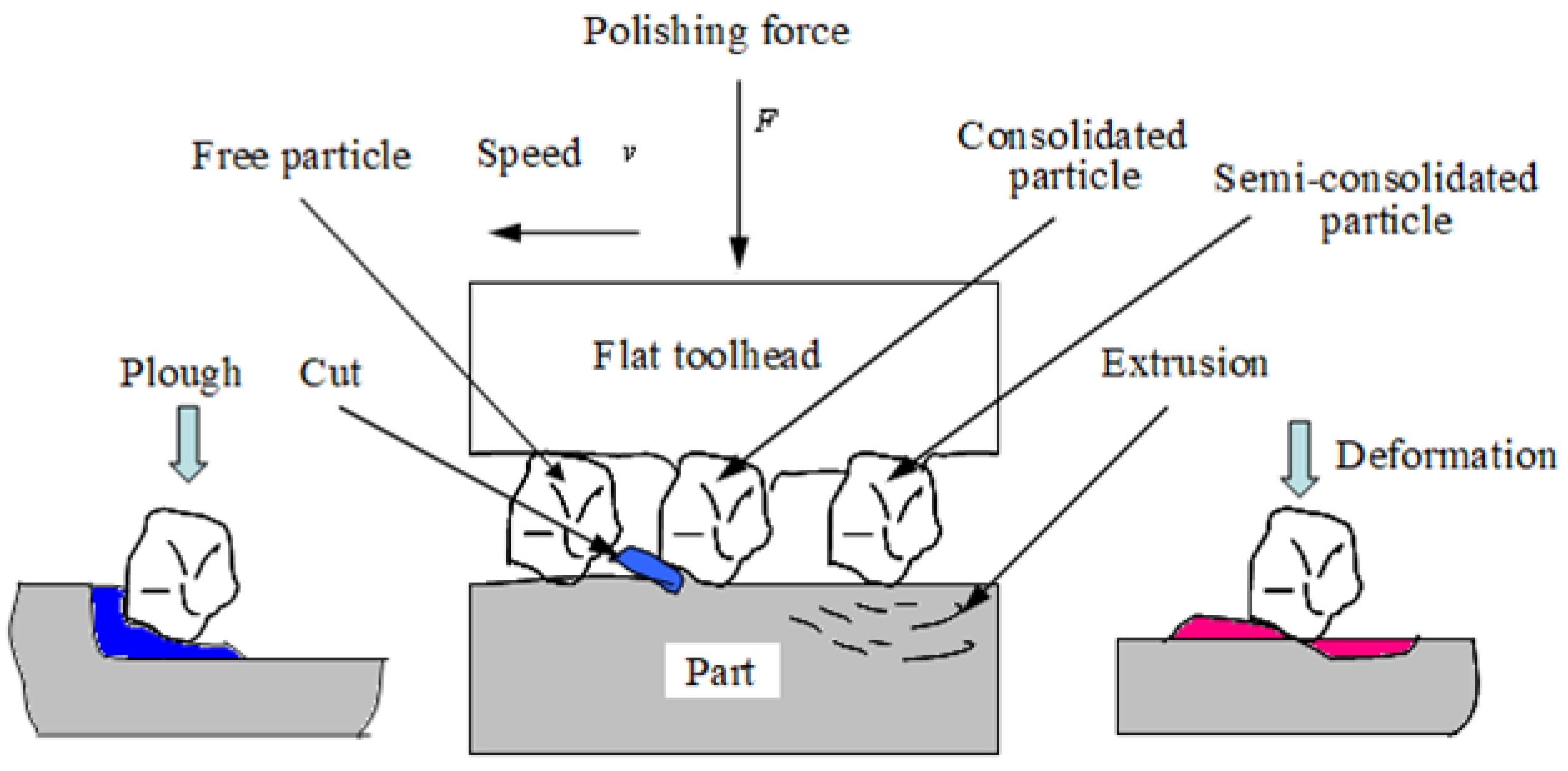
Figure 2.
Process of force-position coupling.
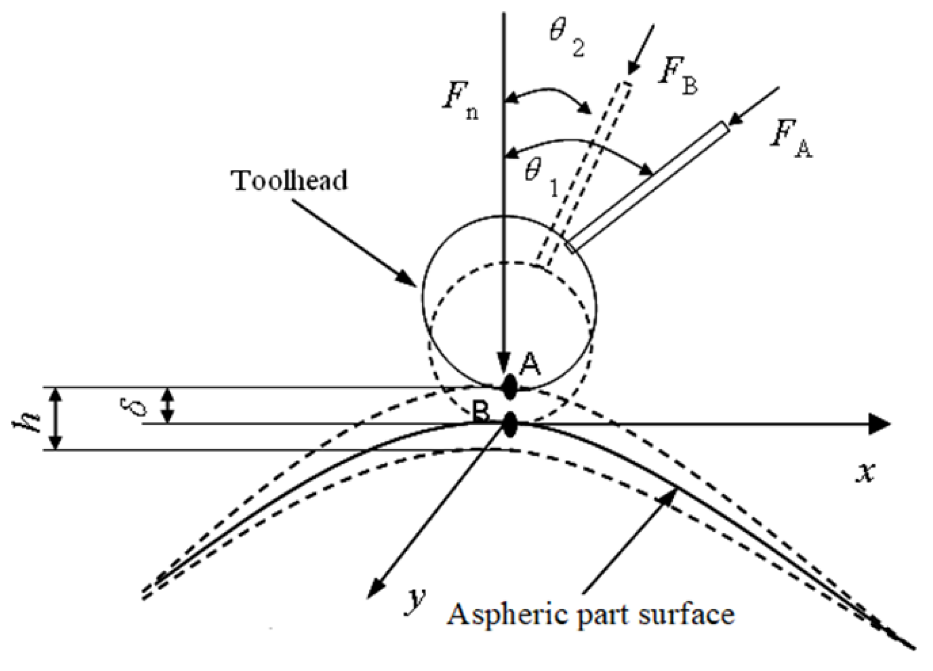
Figure 3.
The change of normal displacement among toolhead, aspheric part and abrasive.
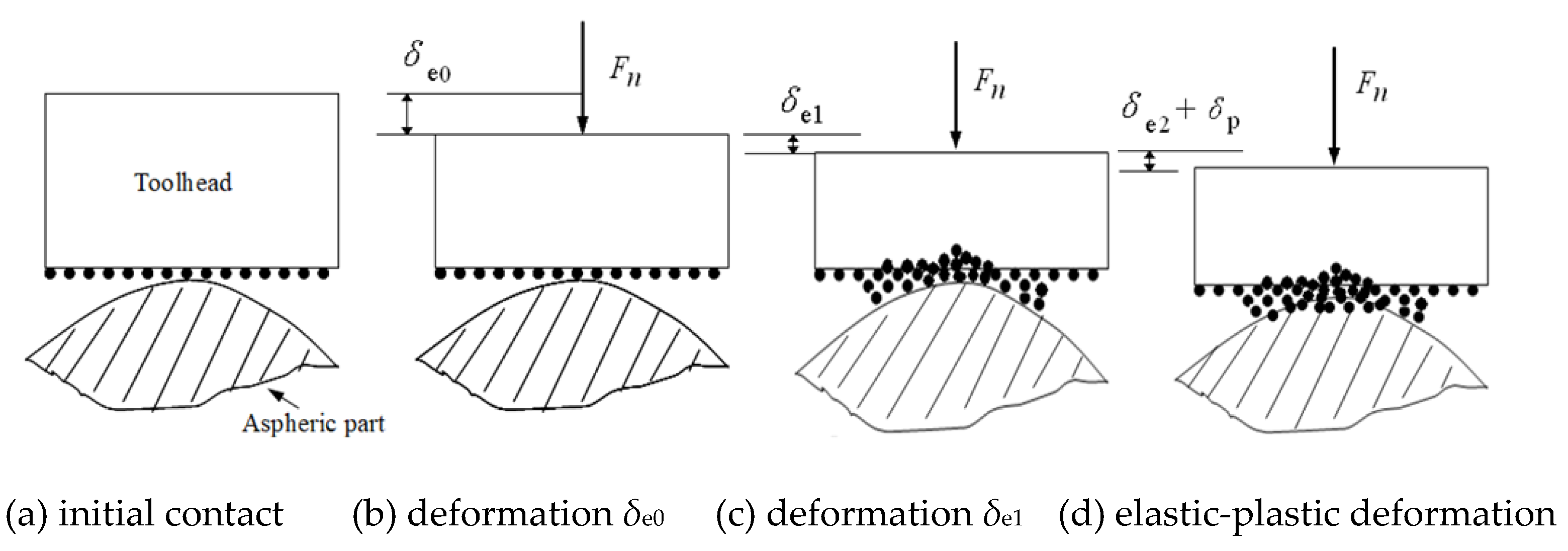
Figure 4.
Micro-contact condition of polishing area.
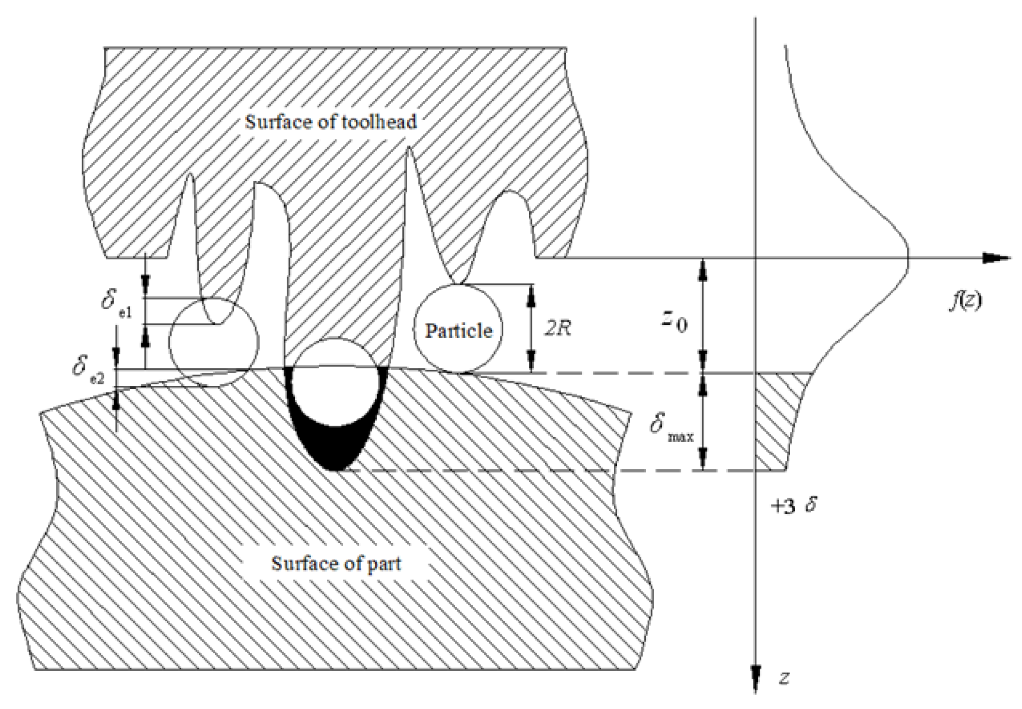
Figure 5.
The micro action process of a single particle.
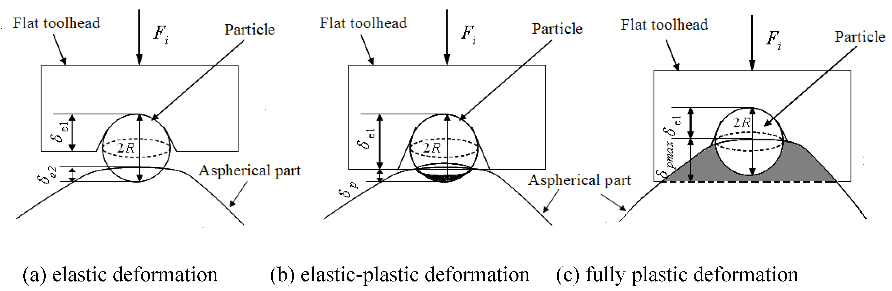
Figure 6.
Polishing system.
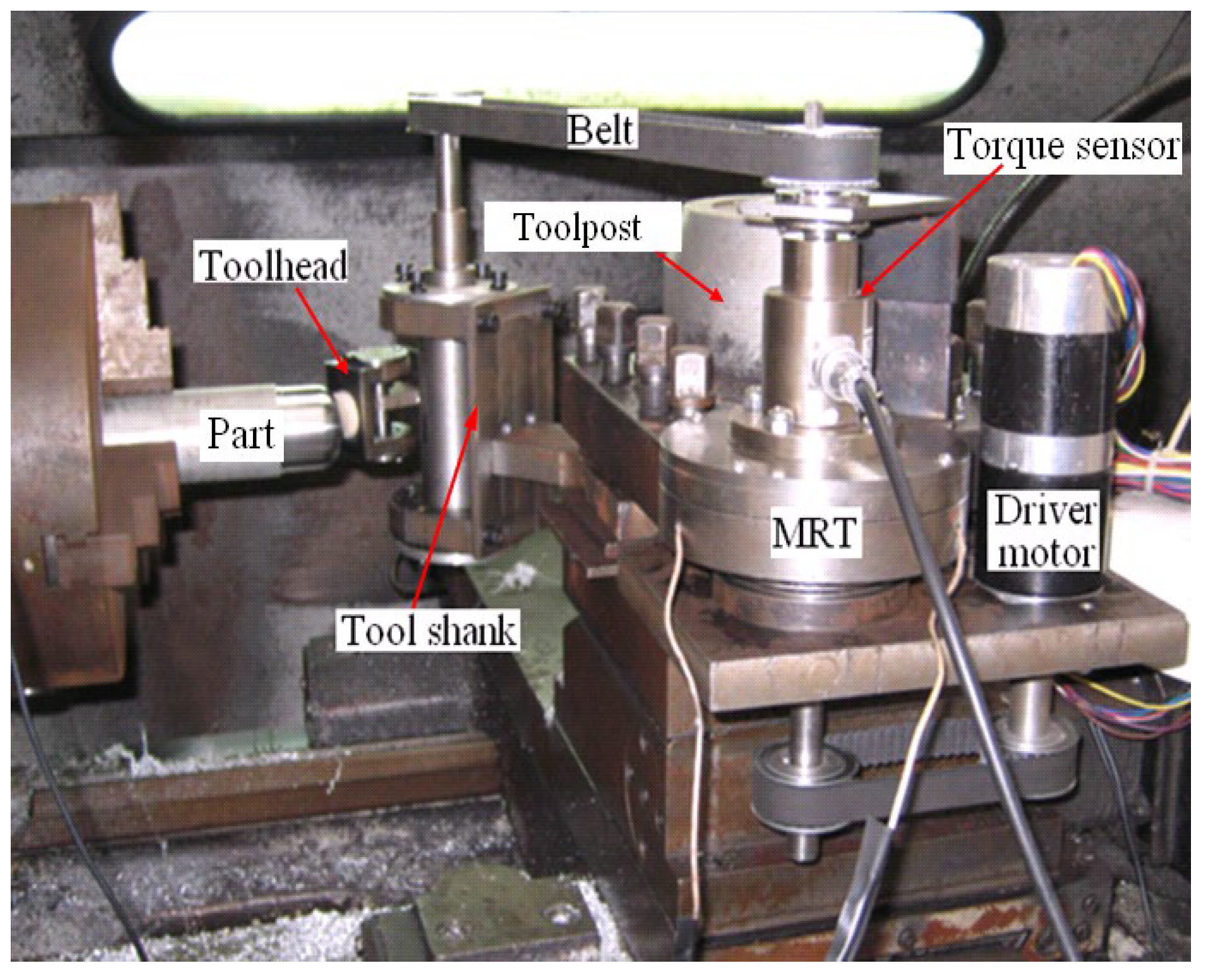
Figure 7.
MRT structure.
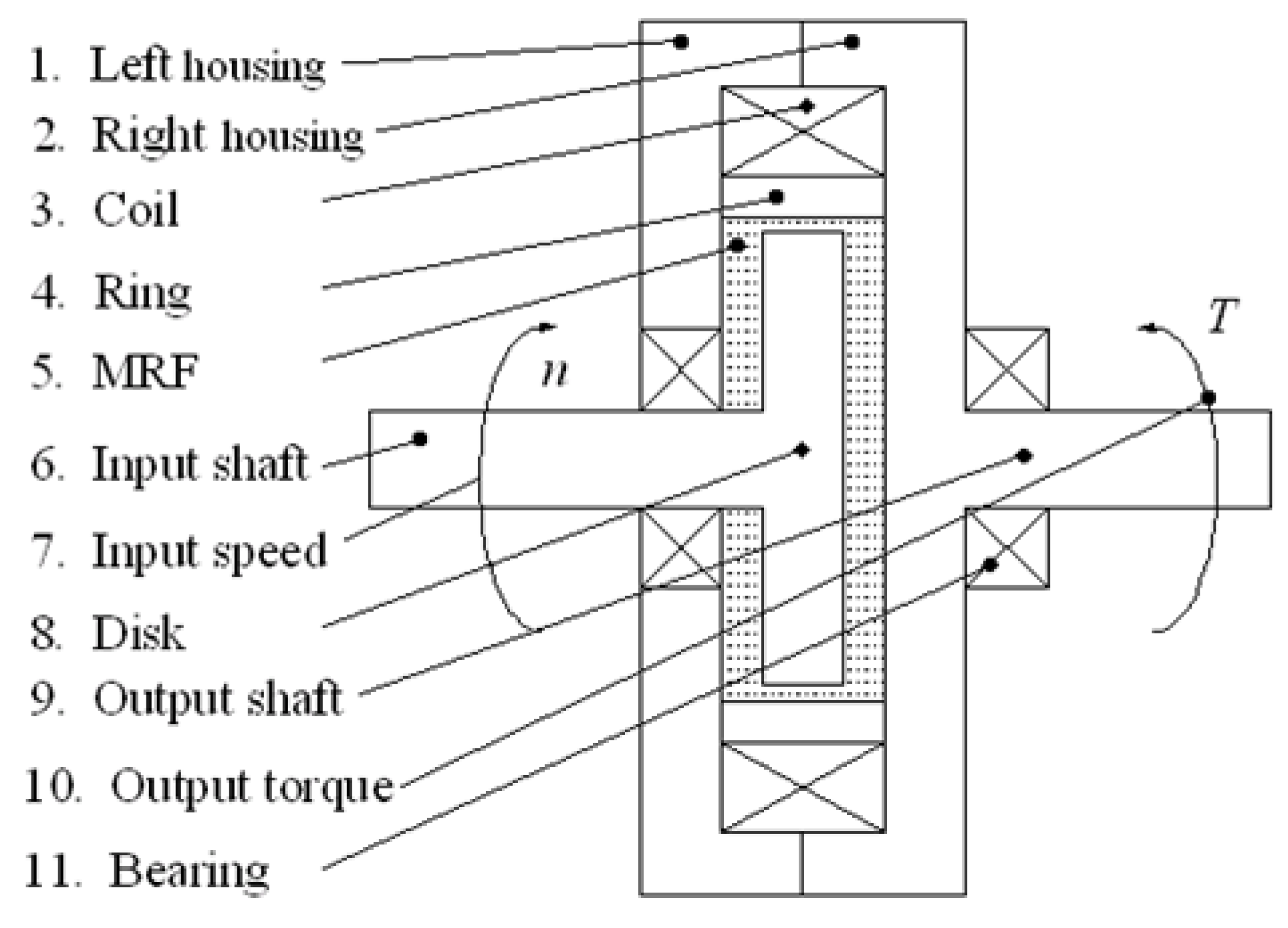
Figure 8.
Trajectory of polishing tool.
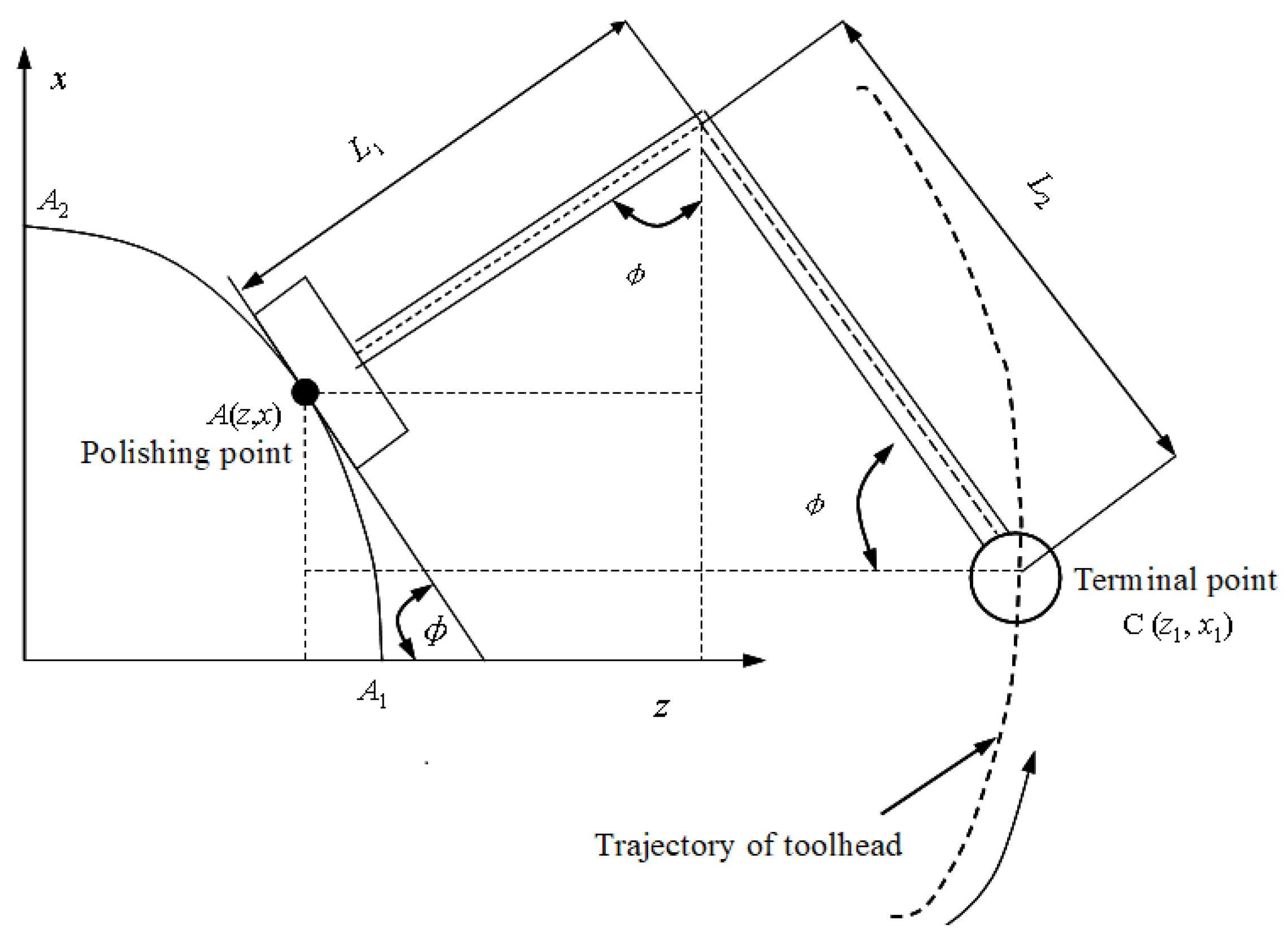
Figure 9.
Surface condition of part before and after polished.
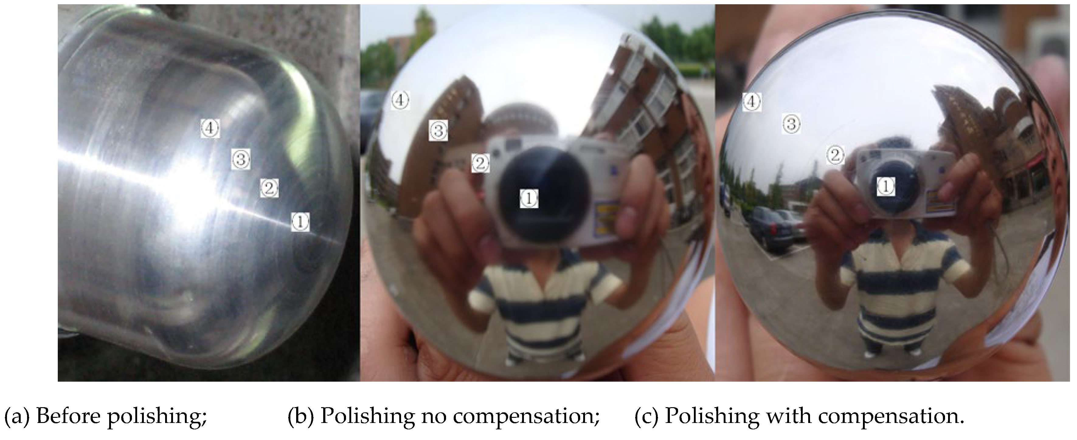

Table 1.
Polishing parameter.
| Classification | Diamond grits | Part | wool felt |
|---|---|---|---|
|
Elastic modulus E(GPa) |
1050 | 70 | 0.015 |
|
Poisson 's ratio ν |
0.2 | 0.34 | 0.079 |
| Brinell hardness HB(GPa) |
102 | 0.06 | - |
Table 2.
Measurement results of surface roughness.
| Areas | Roughness before polishing Ra[µm] |
Roughness after polishing Ra[µm] |
Polishing time t[min] |
|
|---|---|---|---|---|
| Without displacement compensation | With displacement compensation | |||
| ④ ③ ② ① |
1.82 1.62 1.58 1.56 |
0.066 0.051 0.021 0.022 |
0.023 0.021 0.019 0.020 |
45 |
Disclaimer/Publisher’s Note: The statements, opinions and data contained in all publications are solely those of the individual author(s) and contributor(s) and not of MDPI and/or the editor(s). MDPI and/or the editor(s) disclaim responsibility for any injury to people or property resulting from any ideas, methods, instructions or products referred to in the content. |
© 2024 by the authors. Licensee MDPI, Basel, Switzerland. This article is an open access article distributed under the terms and conditions of the Creative Commons Attribution (CC BY) license (http://creativecommons.org/licenses/by/4.0/).
Copyright: This open access article is published under a Creative Commons CC BY 4.0 license, which permit the free download, distribution, and reuse, provided that the author and preprint are cited in any reuse.


