1. Introduction
Zinc Oxide (ZnO) is a well-known n-type II-VI semiconducting metal oxide material widely used in solid-state gas sensor applications due to its wide band gap (3.37 eV), large excitation binding energy (~60meV), high electrical conductivity, low synthesis cost and non-toxicity. ZnO gas sensors have been applied for toxic and harmful gases detection which include Nitrogen Oxide, Hydrogen sulfide, Carbon monoxide, and various volatile organic compounds [
1]. The morphology of the various investigated ZnO gas sensors includes ZnO nanoparticles, one-dimensional (1D), two-dimensional (2D) and three-dimensional (3D) structures [
2,
3,
4,
5], Among the various ZnO gas sensors, the classic ZnO nanorod structure has attracted a lot of attention and has been widely investigated in gas detection due to its high surface-to-volume ratio, nontoxicity, and ease of doping. Numerous methods have been applied to improve the sensing performance of ZnO nanorod gas sensors. For example, dopants like Pd, InSb, Ni and Ca have been introduced to enhance ZnO nanorod gas sensors for improvement of ethanol detection [
6,
7,
8,
9]. However, our present research demonstrates a significant measurable improvement of the sensing performance of ZnO nanorod gas sensors using a novel innovative nested film nanostructure design.
In this study coaxial nested ALD thin film nanotube structures were synthesized to improve the sensing performance of ZnO nanorods to ethanol vapor. The primary objective of the nested coaxial ZnO nanotube design is to provide two additional reaction surfaces compared to the conventional ZnO nanorod gas sensors for each added wrap-around sacrificial layer surrounding the anchoring center ZnO nanorod. Basically, this novel sensor design aims to increase the surface-to-volume ratio further. An ALD 3-D wrap-around Al
2O
3 sacrificial layer was coating each center nanorod to realize a nested coaxial nanotube consisting of free standing ZnO thin films. The sacrificial layer was selectively removed by immersion and dissolution in a Sodium Hydroxide (NaOH) solution due to the different solubility ranges of Al
2O
3 and ZnO [
10].
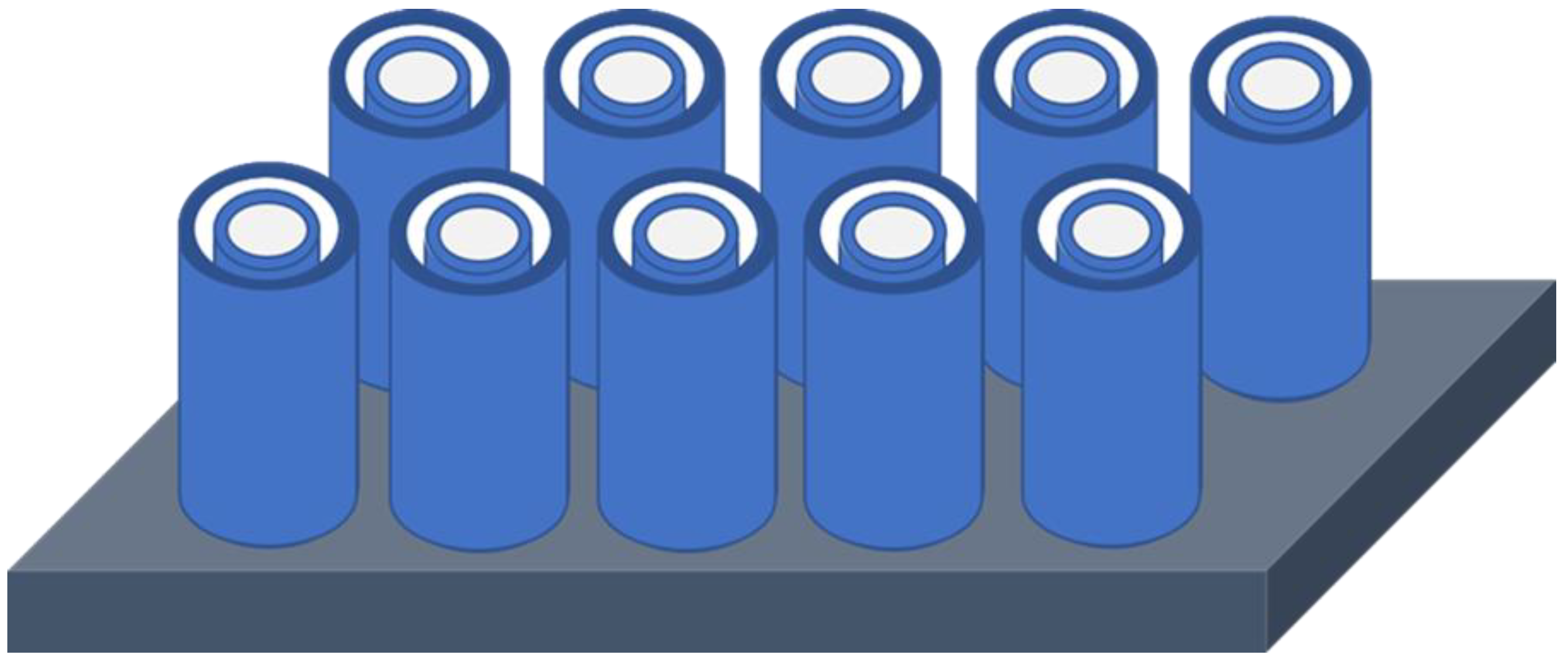
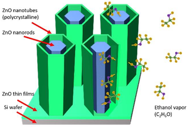
Figure 1 depicts a 3-D schematic drawing of the concept of the co-axial nested tube-in-tube ZnO thin film nanostructure device shown after selective removal of the sacrificial Al
2O
3 layer, which exposes two extra sensing surfaces separating the outer ZnO nanotube from the center ZnO nanorods. These two additional ZnO sensing surfaces fabricated by this novel process design method serve to increase the surface-to-volume ratio and to improve the sensing response of the gas sensor. Due to the average diameter size of ZnO nanorods and the available distance between nanorods synthesized by hydrothermal method, the thickness of the added sacrificial layer and the subsequent ZnO coating are restricted to approximately 20 nm. Therefore, ALD technology was applied to coat the core anchoring ZnO nanorods with 3D wrap-around Al
2O
3 sacrificial layers alternated with ALD ZnO layers with precisely controlled deposition thickness on the nanometer scale. To expose the sacrificial layer for wet etching, PIPS was utilized to remove the accumulated top film covers composed of the ALD Al
2O
3 sacrificial layer and the ZnO thin films deposition.
For the study of the sensing performance of the novel ZnO nanotube gas sensor design to ethanol vapor concentration detection, a newly upgraded gas sensor testing system was designed and custom-built with two mass-flow controllers MFCs to precisely control the concentration of ethanol vapor input. We have investigated the sensing performance of the novel ZnO nanorod gas sensor design and benchmarked our nested coaxial nanotube at different temperatures with saturation level ethanol vapor and at optimum working temperature as a function of various concentrations of ethanol vapor.
2. Materials and Methods
2.1. Sample Preparation
The following process steps were required to fabricate our novel ZnO nanorod/nanotube gas sensors. In this research, a 30 nm ZnO seed layer was deposited on Si substrates by ALD system at a deposition temperature of 200◦C. The two ALD precursors for ZnO seed layer were diethylzinc (Zn(C
2H
5)
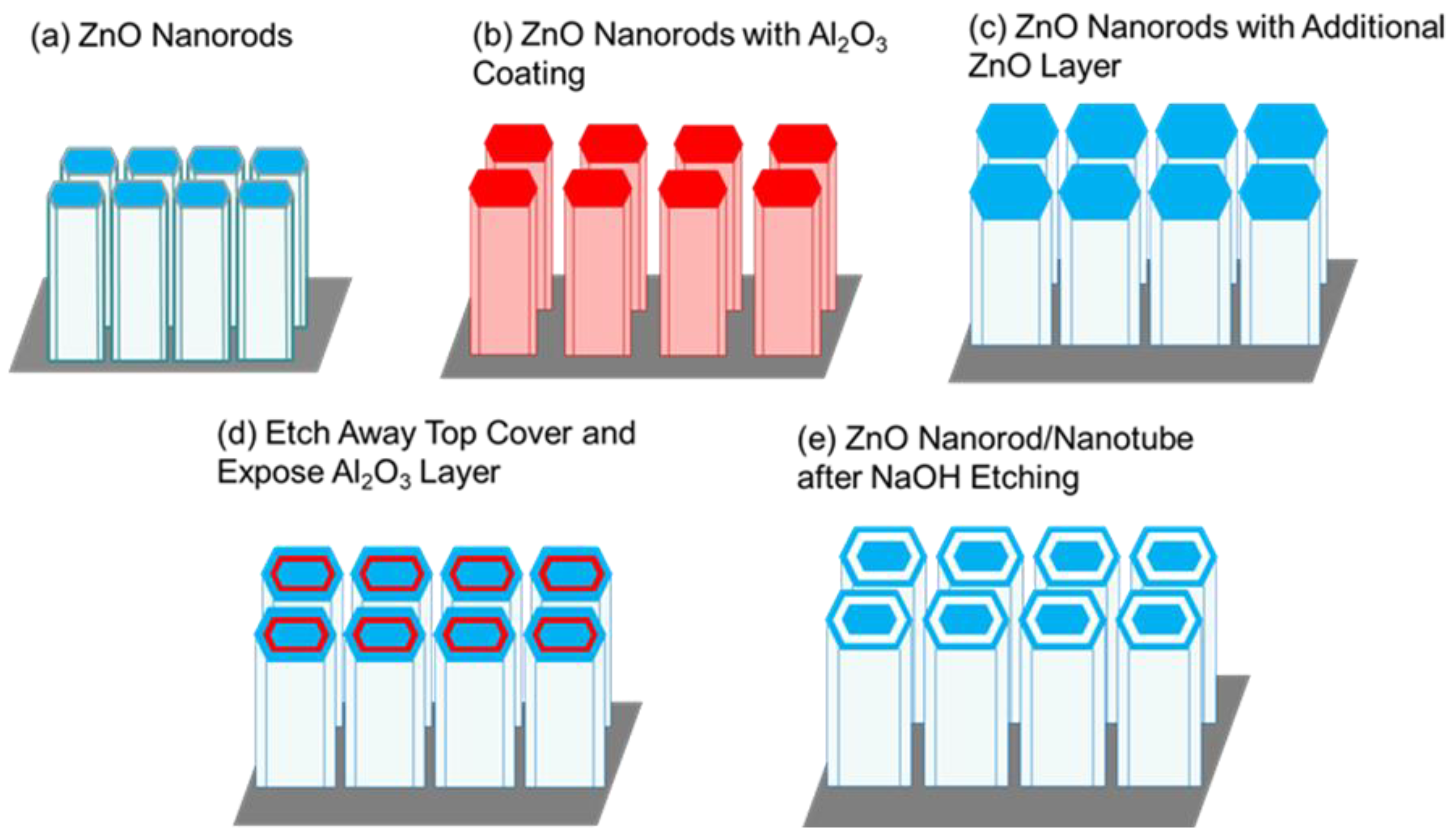
2) and DI water, which were alternatively introduced into the ALD reaction chamber by high purity N2 serving as a carrier gas. After ALD deposition, the ZnO samples was annealed at a temperature of 350◦C for 30 minutes in thermal furnace. Subsequently, the hydrothermal solution crystal growth method was utilized for the initial ZnO nanorod growth on polycrystalline ALD ZnO seed layer, as shown in
Figure 2a. The precursor solution for the ZnO nanorod hydrothermal growth was prepared with 0.03756 g zinc nitrate hexahydrate (Zn(NO
3)6H
2O) and 0.0176 g hexamethylenetetramine ((CH
2)
6N
4) dissolved in 60 ml DI water. This ratio ensured that each chemical precursor had exactly an equal molar concentration of 20.8 mM. Afterwards, vapor phase ALD technology was employed for conformal wrap-around coating of the anchoring ZnO nanorods first with a 20 nm Al
2O
3 sacrificial film followed by a 20 nm ZnO film using the ALD precursors trimethylamine (Al
2(CH
3)
6), diethylzinc (Zn(C
2H
5)
2), and DI water, as shown in
Figure 2b,c. The sacrificial film serves as a “gapfiller” to separate the central hydrothermally grown anchoring ZnO nanorods from the surrounding coaxial nested nanotube film.
Because of the surface saturating growth mechanism of ALD, all surfaces of the ZnO nanorods were completely covered with 20 nm Al
2O
3 sacrificial films followed by another 20 nm ZnO thin film coating. To expose the Al
2O
3 sacrificial film from the top for wet chemical etch dissolution a Precision Ion Polishing System from Gatan Inc. was utilized to remove the surface ZnO/Al
2O
3 ALD films which conformally coated the entire outer surface of the hydrothermal ZnO nanorods as shown in
Figure 2d. After removing the accumulated ALD films only from the top surface, the sacrificial Al
2O
3 annular layer was selectively removed by immersion in an alkali sodium hydroxide solution taking advantage of the different solubility range of Al
2O
3 and ZnO, as shown in
Figure 2e. Solid alumina can exist in solutions with pH values between 4.2 and 9.8, which means the solubility of Al
2O
3 can be considered as below pH 4.2 and above pH 9.8 [
10]. However, crystalized ZnO can only exist in a solution with a pH from 9.2 to 11.5 [
8]. Therefore, an alkali solution was selected to preferentially remove the Al
2O
3 sacrificial layer without chemically attacking and damaging the center ZnO nanorods and nanotubes with pH values between 9.8 and 11.5. For this reason, in this research, a pH 11 sodium hydroxide alkali solution was chosen for the selective wet-etch removal of the sacrificial Al
2O
3 film creating an annular open gap and by this process exposing two additional ZnO reaction surfaces for gas sensing.
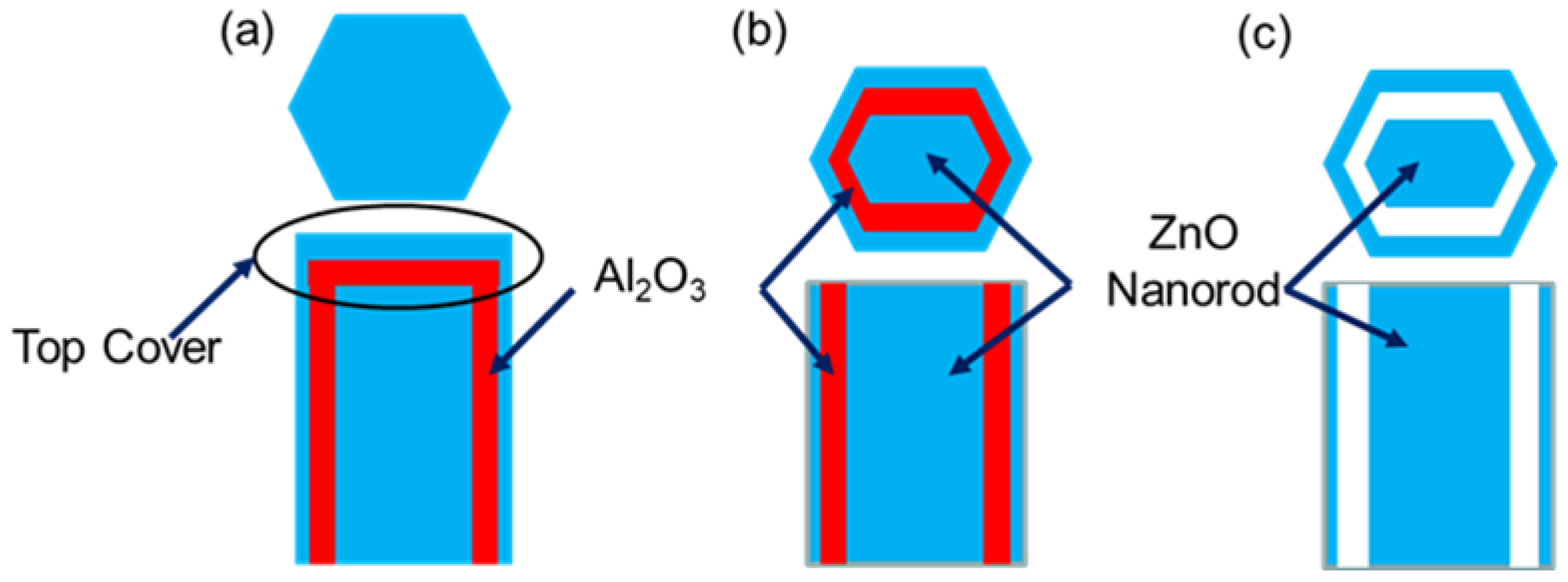
Figure 3 shows a cross-sectional schematic of
Figure 2c–e. On the top of ZnO nanorods several films accumulated due to conformal ALD Al
2O
3 and ZnO depositions, as shown in
Figure 3a. To expose the sacrificial layer from the top, PIPS had to be used to remove the top cover with accurately controlled milling depth shown in
Figure 3b. The samples were then immersed into NaOH solution with a pH of 11 to preferentially etch off the annular sacrificial film. In this fashion a coaxial nested ZnO nanorod/nanotube structure was created exposing two additional reaction surfaces through the remaining open annular gap, as shown
Figure 3c.
2.2. Sensing Response Testing System
To investigate the sensing performance of our novel designed ZnO gas sensors, a gas sensor testing system was designed and custom-built by using a sealed reaction quartz chamber and accurate temperature controller.
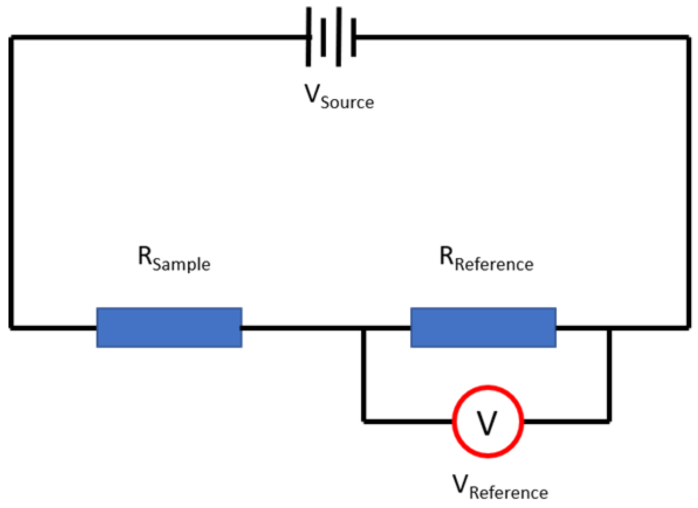
Figure 4 shows the schematic diagram of the testing circuit built in the gas sensor testing system. The nested thin film ZnO nanostructure gas sensor and a reference resistor were installed in a series electrical circuit. A voltage meter was used to measure the voltage changes on the reference resistor.
The sensing response of the novel ZnO gas sensor in this research is related to its DC resistance change and can be measured with an electric circuit. The resistance change is caused by redox surface reactions starting with an initial oxidation reaction between oxygen in atmospheric air and the ZnO sensing surfaces during the set operation heating up the sensor material to the optimum operating temperature. During the oxidation reaction, the majority carriers in n-type ZnO, electrons, are transferred from the conduction band to the oxidizing agent and thereby help forming one layer of negative oxygen ions on the surface of the ZnO nanotubes for the subsequent sensing reduction reaction with the target gas molecules [
11]. This oxidation induced loss of majority carriers results in a decrease of conductivity and a concomitant increase in resistivity. The resistance change of the ZnO nanorod gas sensor was detected and recorded based on Equation 1 to Equation 3, once the ZnO sample was connected to a simple electric circuit design.
where
is the source voltage of the testing circuit,
is the voltage of the measurable reference resistor,
is the current of the testing circuit,
is the resistance of the prepared sample,
is the resistance of the prepared sample at the testing temperature,
is the resistance of the prepared sample at the same testing temperature after introducing the target gas.
The sensing response was calculated based on the resistance change of ZnO nanorod gas sensor relative to the concentration of ethanol vapor as shown in Equation 4 [
12].
Figure 5 shows the resistance change and response change of our novel ZnO nanostructure gas sensor initially after exposure to ethanol target vapor into the test tube at saturation level and optimum operating temperature of 320
, which was followed in the next step by completely exhausting the ethanol from the test set as shown in
Figure 5.
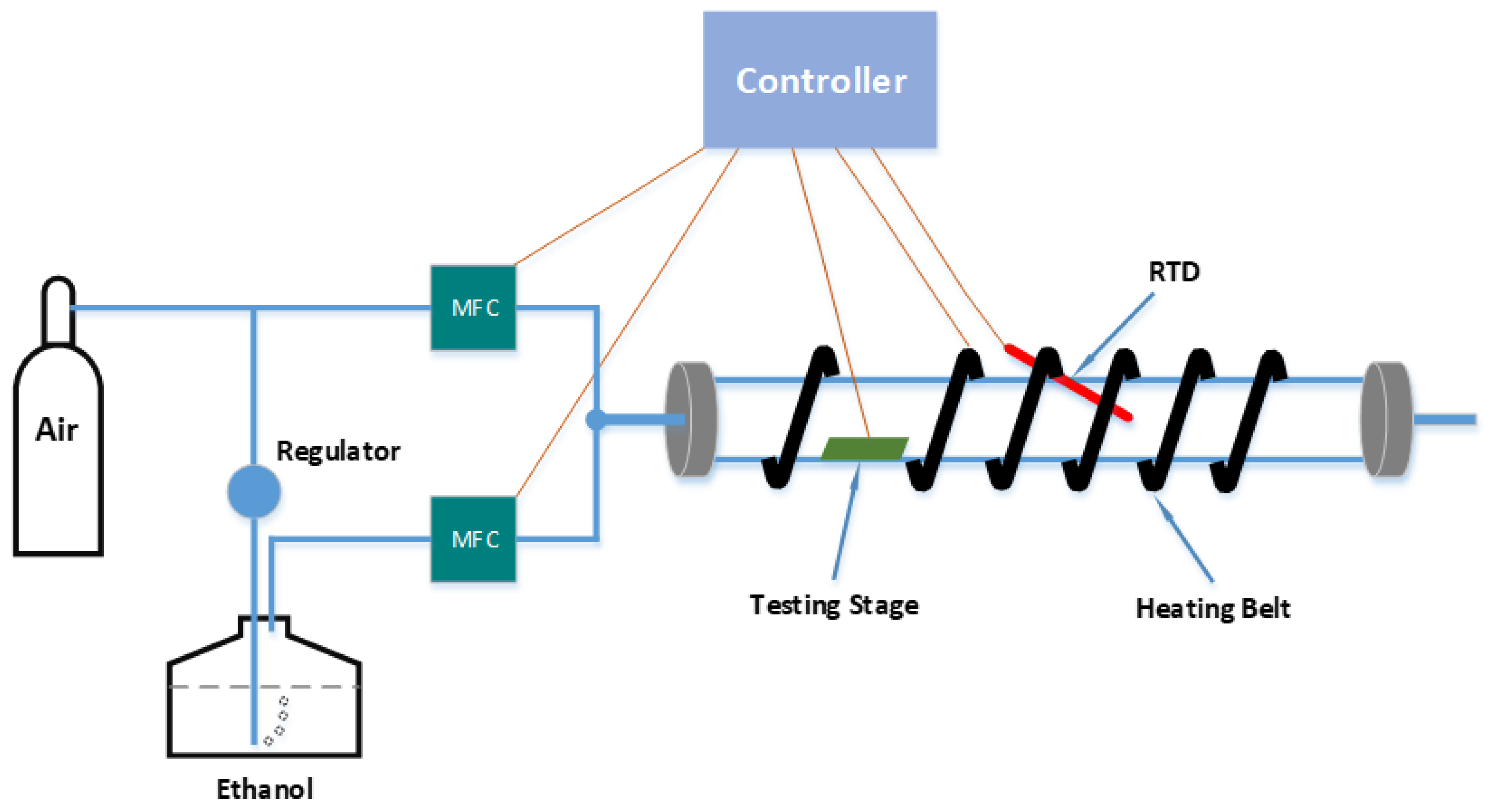
Because the concentration of the ethanol target vapor in the first-generation test system was only approximately controlled by the ethanol volume injected into the test tube by a syringe, a more accurate gas sensor testing system was developed for the upgraded second generation. For a more precise digital control of the concentration of the target gas input, the custom-built testing system was upgraded and rebuilt with two Mass Flow Controllers and a sealed test chamber, as shown in
Figure 6.
The controller was based on the National Instruments Compact Rio 9068 with corresponding modules and has been programmed with LabVIEW. For the temperature control, the controller reads the real-time temperature signal from a Resistance Temperature Detector (RTD) and provides the corresponding control signal to the heater to form a closed loop temperature control. The controller also provides power to the electrical testing circuit and monitors the resistance change of the ZnO gas sensor. To accurately control the concentration of the injected ethanol vapor in the test tube, the controller communicates with the two MFCs by providing input volume signal and reading the real-time input volume signal, which can precisely control the concentration of the ethanol vapor on a ppm scale. The Dubowski equation was used to calculate the injected ethanol vapor concentration [
13], as shown in Equation 5.
where
is the mass concentration of ethanol in vapor phase in mg/L, whereas
is the mass concentration of ethanol in the liquid phase in mg/L, and
is the temperature in
.
3. Results and Discussion
3.1. Physical Characteristics of the ZnO Nanorods and Nested Nanotubes
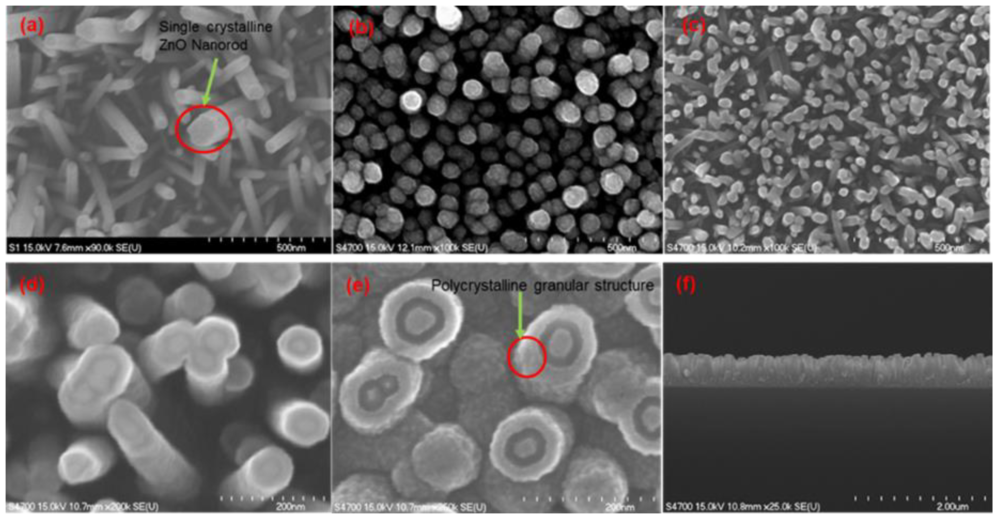
The FE-SEM images of
Figure 7a–e highlight the resulting morphology at the various stages of the entire sequence of the nested ZnO thin film nanorod/nanotube gas sensor synthesis process.
Figure 7a shows the ZnO nanorods grown by the hydrothermal method, which clearly reveals single crystalline ZnO nanorods with a crystallographic hexagonal cross-section structure. Following 3-D wrap-around coatings with an ALD Al
2O
3 sacrificial film and on top of it another ZnO ALD film coating, the surface of the center ZnO nanorods was covered and sealed with a top ZnO covering, as shown in
Figure 7b. The PIPS process was utilized to remove the top cover and to expose the Al
2O
3 sacrificial layer from the top as shown in
Figure 7c,d. Afterwards the sacrificial alumina layer was preferentially removed by wet chemical dissolution in an NaOH alkali solution. This constitutes a key process step in our novel sensor design and isolated the center hydrothermal ZnO nanotubes. The creation of an empty annular gap remaining after the removal of the sacrificial layer exposed two additional reaction sensing surfaces as shown in
Figure 7e.
Figure 7f shows a cross-sectional view of the ZnO nanorod/nanotube gas sensors revealing an average height of nanorods of ~750 nm.
3.2. Sensing Response Analysis as a Function of Temperature
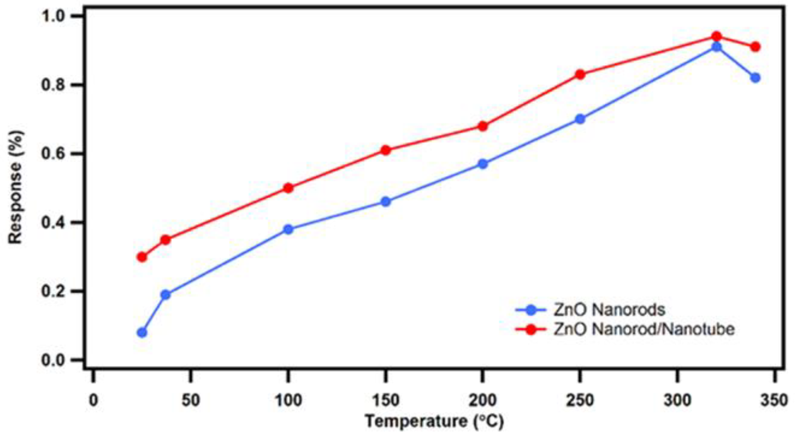
At the onset, our novel nested ZnO nanorod/nanotube gas sensors were tested at a constant saturation level ethanol vapor concentration of 1000 ppm as a function of temperature from 25
to 340
. A sensing response comparison between our novel ZnO nanorod/nanotube gas sensor design and conventional ZnO nanorod gas sensors was performed, as shown in
Figure 8. In both cases, the sensing response results of the novel nested ZnO thin film nanorod/nanotube gas sensors compared to the conventional ZnO nanorod gas sensors demonstrate that the sensitivity response improves steadily with increasing temperature until a maximum value at 320
is reached, which constitutes the optimum working temperature. After reaching the maximum peak at 320
, any further increase in temperature causes a decrease in sensitivity. In general, after the operating temperature exceeds the optimum peak temperature, the sensing response of the ZnO nanostructure gas sensor decreases. This is attributed to the faster temperature activated reaction ratio of the reduction reaction compared to the slower oxidation reaction ratio. At higher temperatures, there are more electrons adsorbed on the surface of ZnO from the conduction band, which causes an increase of the resistance and a decrease on the response change. Therefore, the sensing response of ZnO nanostructure gas sensors suffers a decrease at higher temperatures beyond the optimum working temperature.
Based on the comparison of the response versus temperature data shown in
Figure 8, the novel nested ZnO thin film nanorod/nanotube gas sensor design exhibits a significant improvement in sensing response compared to the conventional ZnO nanorod gas sensors. The advantage gets more pronounced at lower temperatures, while the response difference between the two sensor designs narrows down as the temperature approaches the optimum peak operating temperature. The observed enhancement in the sensing response is primarily attributed to the increased surface-to-volume ratio, which was experimentally realized by our novel nested nanotube sensor design. After removing the Al
2O
3 sacrificial layer, a novel ZnO nanorod sensor was synthesized with coaxial nanotubes structure, where the resulting empty annular ring space generated two additional ZnO reaction surfaces. Therefore, the chemical dissolution & removal of the Al
2O
3 sacrificial layer uncovered more reaction surfaces for ethanol vapor sensing in the same sized area, which in turn resulted in a sizeable increase of the surface-to-volume ratio.
3.3. Sensing Response Analysis as a Function of Various Ethanol Vapor Concentrations
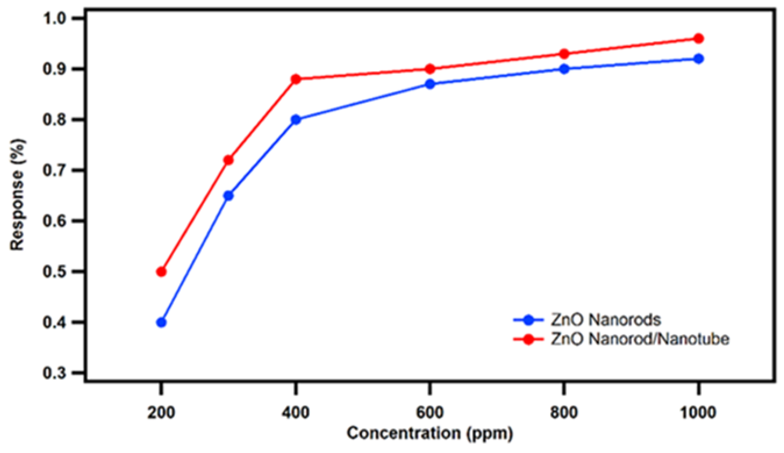
Subsequently, the novel ZnO nanorod/nanotube gas sensors and conventional ZnO nanorod gas sensors were tested as a function of various of ethanol vapor concentrations ranging from 200 ppm to 1000 ppm at the confirmed optimum working temperature of 320
. The sensing response comparison between our novel nested ZnO nanorod/nanotube gas sensors and conventional ZnO nanorod gas sensors is shown in the plot of
Figure 8. Both sensing responses increase with increasing ethanol vapor concentration until they reach their saturation level. However, our novel nested ZnO thin film nanorod/nanotube gas sensor design has achieved a higher sensing response compared to the conventional ZnO nanorod gas sensors from the comparison benchmark. It is especially noteworthy that the saturation level of our novel nested ZnO nanorod/nanotube gas sensor (1000 ppm) is higher than the level of the conventional ZnO nanorod gas sensor (800 ppm). The increased saturation level for the nested coaxial nanorod-in-nanotube approach is attributed to the available increased reaction surface from the ZnO nanotube, which leads to an increased surface-to-volume ratio. As a result, the saturation level of ZnO nanorod gas sensors is improved to 1000 ppm with the use of novel nested coaxial ZnO nanotubes.
.
3.4. Gain in Sensing Response Enhancement
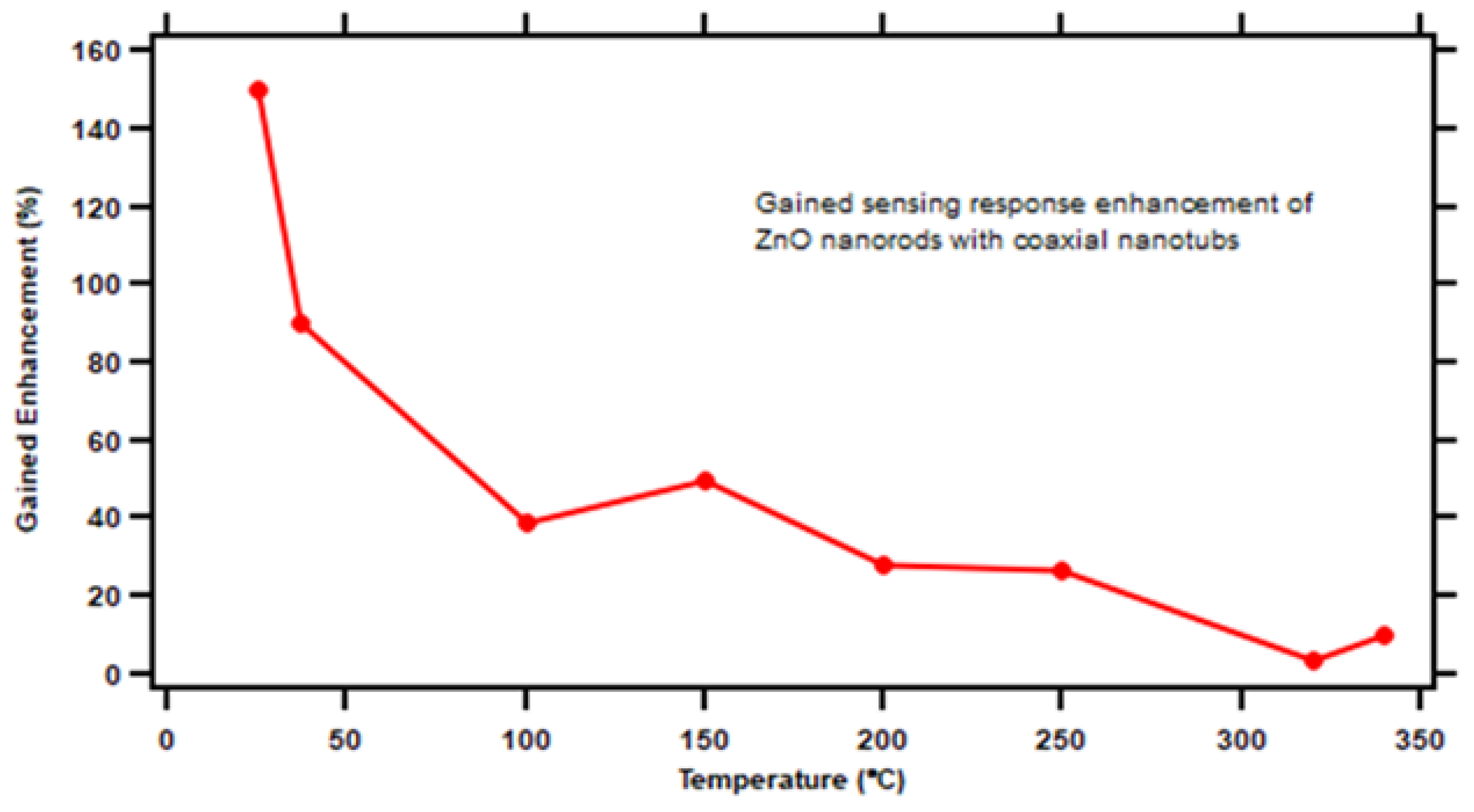
With increased surface-to-volume ratio, the sensing response of our novel nested ZnO nanorod/nanotube gas sensor design is improved compared to the original ZnO nanorod gas sensors.
Figure 10 shows the additional enhancement gain of the novel nested ZnO nanorod/nanotube gas sensor when the sensor was operated under saturation level concentration of ethanol target vapor at different temperatures. The maximum enhancement gain reached approximately 150% at 25
. The calculation formula is shown in Equation 6.
where
is the sensing response of the nested ZnO nanorod/nanotube gas sensors at saturation level concentration of ethanol vapor, while
is the sensing response of the original ZnO nanorod gas sensors at saturation level concentration of ethanol vapor at the same temperature.
3.5. The Relationship between Surface-to-Volume Ratio and Sensitivity
During the gas detection step upon exposure to a reducing target gas, a reduction reaction occurs on the surface of ZnO gas sensors. Hereby, the following sensing reaction takes place between oxygen negative ions pre-existing on the sensor surface from the set operation and the reducing target gas molecules, as shown in Equation 7 [
14].
where
is the target reducing gas,
is the byproduct after the reaction, and
is the number of electrons.
Based on Equation 7, the electron density adsorbed to the surface can be calculated by Equation 8 [
15].
where
is the electron density under the target gas atmosphere,
is a time constant,
is the electron density under the air atmosphere,
is variable value (equal to 1 for
and 0.5 for
), [O] is the adsorbed oxygen ion density,
is the target gas molecule density, and
is the reaction rate constant [
13]. Therefore, based on Equation 4, the sensitivity relation is shown in Equation 9.
where
is the sensing response of the gas sensor. Conventionally, the surface-to-volume ratio can be defined by the adsorbed oxygen ion density [
13]. Therefore, the adsorbed oxygen ion density can be defined by Equation 10.
where
is the number of oxygen ions per unit area,
is the volume of the gas-sensitive material,
is the ratio of surface area per volume of material (
), and
is the volume of the reaction chamber of the gas testing system [
13]. After substituting Equation 10 to Equation 9, we can get the sensitivity of the gas sensor related to the surface-to-volume ratio from Equation 11.
Equation 11 clearly explains the relationship between the sensitivity and the surface-to-volume ratio of MOS solid-state gas sensors. These equations provide much of the motivation background for this work and the conception of the novel nested ZnO thin film sensor design architecture. With increased surface-to-volume ratio ( and ) introduced by additional layers coating the coaxial ZnO nanotube, among them the sacrificial Al2O3 layer, the sensitivity of ZnO gas sensors to the ethanol vapor concentration detection correspondingly increases based on Equation 11. Consequently, the sensitivity of ZnO nanorod gas sensors can be improved with an increased surface-to-volume ratio, which in our case is being realized by coaxial ZnO nanotubes, that expose two additional reaction surfaces after removal of the sacrificial alumina layer. It is also apparent that the process of ALD synthesis of wrap-around sacrificial films and ZnO sensing films can be continued to create even more complex nested ZnO thin film nanostructures by adding additional nested films. Each new coaxial ZnO film will further improve the surface-to-volume ratio and the device sensitivity. Depending on the application the device sensitivity can be increased to the desired device sensitivity by adding n-numbers of additional free-standing coaxial ZnO films.
4. Conclusions
A novel nested coaxial ZnO thin film nanorod/nanotube gas sensor architecture was fabricated by an integrated process combining hydrothermal growth of single crystal nanorod center anchors, followed by subsequent 3-D wrap-around coatings of sacrificial ALD alumina films alternating with ALD ZnO polycrystalline films. This novel nested ZnO thin film gas sensor architecture was examined by a newly upgraded gas sensor testing system connected with digital mass flow controllers for precise target vapor concentration. At the start, ZnO nanorods were synthesized by the hydrothermal method on a fine grain polycrystalline ZnO seed layer deposited by ALD to anchor the final complex nested sensor nanostructure. An ALD Al2O3 sacrificial layer was a key concept to create nested coaxial ZnO thin film nanotubes. After removing accumulated ALD films from the top surface by PIPS, the Al2O3 sacrificial layer was preferentially removed by wet chemical etching in a NaOH solution with pH 11. Consequently, a nested ZnO nanorod/nanotube structure was created with two additional reaction surfaces, which provide a significant increase in surface-to-volume ratio. In principle our approach is amenable to add more than one sacrificial layer and additional ZnO sensing films. Theoretically every additional annular sacrificial layer will add two new ZnO reaction surfaces available for sensing after wet chemical etch removal. With increasing reaction surfaces and sites, the sensing response of nested ZnO thin film nanorod gas sensors achieved a significant response enhancement employing nested coaxial ZnO nanotubes with empty annular sacrificial layers. Especially, the saturation level was improved from 800 ppm to 1000 ppm. Compared to conventional ZnO nanorod gas sensor benchmarks, our novel nested ZnO nanotube gas sensors achieved a sensing response improvement of roughly 150% at a low temperature of 25. In summary, this work demonstrates that our nanotechnology process design of creating empty annular gaps surrounding free-standing nested ZnO nanotubes is effective in increasing the surface-to-volume ratio and to significantly improve the sensing response of ZnO solid-state gas sensors. This nested nanotube technology with sacrificial layers represents a pathway for further improvement of the sensitivity response and a higher saturation level and thereby enhancing the application potential of ZnO gas sensors.
References
- Kang, Y.; Yu, F.; Zhang, L.; Wang, W.; Chen, L.; Li, Y. Review of ZnO-based nanomaterials in gas sensors. Solid State Ionics 2021, 360, 115544. [Google Scholar] [CrossRef]
- Khan, M.W.A.; Shaalan, N.M.; Ahmed, F.; Sherwani, S.; Aljaafari, A.; Alsukaibi, A.K.D.; Alenezi, K.M.; Al-Motair, K. Gas Sensing Performance of Zinc Oxide Nanoparticles Fabricated via Ochradenus baccatus Leaf. Chemosensors 2024, 12, 28. [Google Scholar] [CrossRef]
- Aleksanyan, M.; Sayunts, A.; Shahkhatuni, G.; Simonyan, Z.; Shahnazaryan, G.; Aroutiounian, V. Gas Sensor Based on ZnO Nanostructured Film for the Detection of Ethanol Vapor. Chemosensors 2022, 10, 245. [Google Scholar] [CrossRef]
- Wang, L.; Kang, Y.; Liu, X.; Zhang, S.; Huang, W.; Wang, S. ZnO Nanorod Gas Sensor for Ethanol Detection. Sens. Actuators B: Chem. 2012, 162, pp. 237–243. [Google Scholar] [CrossRef]
- Hsueh, T. J.; Chang, S. J.; Hsu, C. L.; Lin, Y. R.; Chen, I. C. Promotion of the Electrochemical Activity of a Bimetallic Platinum-Ruthenium Catalyst by Oxidation-Induced Segregation. J. Electrochem. Soc. 2008, 155, pp. 152–155. [Google Scholar] [CrossRef]
- Kim, H.; Pak, Y.; Jeong, Y.; Kim, W.; Kim, J.; Jung, G. Y. Amorphous Pd-assisted H2 Detection of ZnO Nanorod Gas Sensor with Enhanced Sensitivity. Sens. Actuators B. 2018, 262, pp. 460–468. [Google Scholar] [CrossRef]
- Kakati, N.; Jee, S. H.; Kim, S. H.; Lee, H. K.; Yoon, Y. S. Sensitivity Enhancement of ZnO Nanorod Gas Sensors with Surface Modification by an InSb Thin Film. Japanese J. Appl. Phys. 2009, 48, 105002. [Google Scholar] [CrossRef]
- Xu, M.; Li, Q.; Ma, Y.; Fan, H. Ni-doped ZnO Nanorods Gas Sensor: Enhanced Gas-sensing Properties, C and DC Electrical Behaviors. Sens. Actuators B. 2014, 199, pp. 403–409. [Google Scholar] [CrossRef]
- Hjiri, M.; Algessair, S.; Dhahri, R.; Albargi, H. B.; Mansour, N. B.; Assadid, A. A.; Neri, G. Ammonia gas sensors based on undoped and Ca doped ZnO nanoparticles. RSC Adv. 2024, 14, pp. 5001–5011. [Google Scholar] [CrossRef]
- Gu, D.; Baumgart, H. ; Abdel-Fattah, Namkoong, T. M.; G. Synthesis of Nested Coaxial Multiple-Walled Nanotubes by Atomic Layer Deposition. ACS Nano. 2010, 4, pp. 753–758. [Google Scholar] [CrossRef]
- Lin, P.; Chen, X.; Zhang, K.; Baumgart, H. Improved Gas Sensing Performance of ALD AZO 3-D Coated ZnO Nanorods, ECS J. Solid State Sci. Technol. 2018, 7, pp. 246–252. [Google Scholar] [CrossRef]
- Prajapati, C. S.; Sahay, P. P. ; Alcohol-sensing Characteristics of Spray Deposited ZnO Nano-particle Thin Films. Sens. Actuators B: Chem. 2011. 160, 1043. [CrossRef]
- Pratzler, S.; Knopf, D.; Ulbig, P.; Scholl, S. ; Preparation of Calibration Gas Mixtures for the Measurement of Breath Alcohol Concentration. J. Breath Res. 2010, 4, 036004. [Google Scholar] [CrossRef] [PubMed]
- Supab, C.; Niyom, H.; Ekasiddh, W. Metal-Oxide Nanowires for Gas Sensor, Nanowires-Recent Advances 2012, Chapter 1. [CrossRef]
- Hongsith, N.; Wongrat, E. Kerdcharoen, T. ; Choopun, S. Sensor Response Formula for Sensor Based on ZnO Nanostructures. Sens. Actuators B: Chem. 2010, 144, pp. 67–72. [Google Scholar]
Figure 1.
Schematic 3-D drawing illustrating the concept of the co-axial nested tube-in-tube nanostructure design after removal of the sacrificial Al2O3 film separating the outer nanotube from the center nanotube, thereby exposing two new ZnO gas sensing surfaces.
Figure 1.
Schematic 3-D drawing illustrating the concept of the co-axial nested tube-in-tube nanostructure design after removal of the sacrificial Al2O3 film separating the outer nanotube from the center nanotube, thereby exposing two new ZnO gas sensing surfaces.
Figure 2.
Schematic of process sequence fabricating coaxial nested ZnO nanorods starting with (a) single crystal ZnO nanorods by hydrothermal solution growth, (b) ZnO nanorods coated with ALD wrap-around Al2O3 sacrificial film, (c) ZnO nanorods receiving an additional coaxial wrap-around ALD ZnO film outer coating, (d) surface ALD film accumulation removed by PIPS, (e) final structure of coaxial nested wrap-around ZnO film nanostructure following the selective removal of the sacrificial film by NaOH dissolution thereby creating the empty annular gap to expose additional sensing surfaces of the ZnO film.
Figure 3.
Cross-sectional schematic of (a) ZnO nanorod with ALD Al2O3 sacrificial film and ZnO film, (b) top ALD coatings removed by PIPS, (c) final completed nested ZnO nanotube structure after NaOH etch removal of the sacrificial alumina film exposing additional ZnO sensing surfaces.
Figure 3.
Cross-sectional schematic of (a) ZnO nanorod with ALD Al2O3 sacrificial film and ZnO film, (b) top ALD coatings removed by PIPS, (c) final completed nested ZnO nanotube structure after NaOH etch removal of the sacrificial alumina film exposing additional ZnO sensing surfaces.
Figure 4.
Schematic diagram of the testing circuit built in the gas sensor testing system.
Figure 4.
Schematic diagram of the testing circuit built in the gas sensor testing system.
Figure 5.
Plots of Resistance change and Response change as a function of time of nested thin film ZnO nanostructure gas sensors delineating the response after introducing and exhausting the ethanol target vapor in a sealed testing chamber.
Figure 5.
Plots of Resistance change and Response change as a function of time of nested thin film ZnO nanostructure gas sensors delineating the response after introducing and exhausting the ethanol target vapor in a sealed testing chamber.
Figure 6.
Schematic diagram of the improved 2nd generation gas sensor testing system.
Figure 6.
Schematic diagram of the improved 2nd generation gas sensor testing system.
Figure 7.
FE-SEM images of the novel nested ZnO thin film nanorod/nanotube coaxial structure synthesis process (a) intrinsic hydrothermal ZnO nanorods with hexagonal wurtzite structure, (b) polycrystalline wrap-around ALD coating on ZnO nanorods after coating with an Al2O3 sacrificial film and ZnO thin films, (c) and (d) top cover removed by PIPS ion milling to expose the sacrificial layer, (e) the sacrificial layer preferentially etched away by pH 11 NaOH solution, and (f) cross-section revealing an average height of nanorods of ~750 nm.
Figure 8.
Sensing response result comparison between the novel nested ZnO thin film nanorod/nanotube gas sensors with sacrificial annular gap (red curve) and the conventional ZnO nanorod gas sensors (blue curve) sensing response to saturation level ethanol vapor concentration as a function of operating temperature.
Figure 9.
Sensing response comparison between the novel nested ZnO thin film nanorod/nanotube gas sensors with sacrificial annular gap (red curve) and the conventional ZnO nanorod gas sensor (blue curve) sensing response as a function of different ethanol vapor concentration at optimum operating temperature of 320
Figure 10.
Gained sensing response enhancement of ZnO nanorod with nested coaxial nanotubes as a function of operating temperature.
Figure 10.
Gained sensing response enhancement of ZnO nanorod with nested coaxial nanotubes as a function of operating temperature.
|
Disclaimer/Publisher’s Note: The statements, opinions and data contained in all publications are solely those of the individual author(s) and contributor(s) and not of MDPI and/or the editor(s). MDPI and/or the editor(s) disclaim responsibility for any injury to people or property resulting from any ideas, methods, instructions or products referred to in the content. |
© 2024 by the authors. Licensee MDPI, Basel, Switzerland. This article is an open access article distributed under the terms and conditions of the Creative Commons Attribution (CC BY) license (http://creativecommons.org/licenses/by/4.0/).

