Preprint
Review

A Review on Ex-Vessel Melt Retention Measures Adopted in Light Water Reactors

Altmetrics

Downloads

86

Views

43

Comments

0

A peer-reviewed article of this preprint also exists.

Submitted:

01 October 2024

Posted:

02 October 2024

You are already at the latest version

Alerts
Abstract
As the cornerstone of severe accident management strategy, either in-vessel or ex-vessel retention of core melt (IVR or EVR) plays a pivotal role in the stabilization and termination of a severe accident, and ultimately secures the safety goal of “Practical elimination of large radioactive release” for light water reactors. In contrast to the IVR measures that are more or less identical in reactor designs, the EVR measures are quite different from design to design. This paper was intended to give a critical review on the EVR measures adopted in the reactor designs of VVER-1000, EPR, ESBWR, EU-APR1400 and APWR. The review study began with a general description of the existing EVR measures, including their principles, operational procedures and research efforts. We then focused our discussions on the pros and cons of each EVR measure, through the comparisons with the IVR and with the others in terms of simplicity, reliability and economy. We finally tried to identify the remaining issues and uncertainties in the qualification of the EVR measures, based on which potential design improvements and future research needs were recommended.
Keywords: 
Subject: Engineering  -   Energy and Fuel Technology

1. Introduction

In a severe accident scenario of a light water reactor (LWR), the fuel assemblies in the reactor core will heat up and melt down due to insufficient cooling on the core for decay heat removal. The mixture of molten fuel (UO2) and control rod materials as well as molten oxide of cladding (Zircaloy) and structure material (stainless steel) forms the corium which further relocates into the lower head of the reactor pressure vessel (RPV) and forms a melt pool. A severe accident management (SAM) strategy can be implemented to flood the reactor cavity upon a signal of core damage, so as to cool and retain the corium in the RPV through external cooling of the lower head. This SAM strategy is the so-called In-Vessel Retention (IVR) of corium, which was first proposed for the back-fitting of the Generation-II reactor Loviisa VVER 440 to cope with corium risk [1], and then adopted in the Generation-III designs such as the advanced pressurized water reactors (PWRs): Westinghouse AP600 [2] and AP1000 [3], the Korean APR1400 [4], the Chinese HPR1000 [5] and CAP1400 [6], as well as the advanced boiling water reactor (BWR): AREVA KERENA [7].
If the corium melt pool in the RPV lower head could not be sufficiently cooled by coolant flow in the reactor cavity (e.g., for a reactor with very high power capacity), the corium will finally melt through the vessel wall and discharge into the wet cavity underneath the RPV. This brings about the risk of steam explosion which results from energetic molten fuel coolant interactions (FCI) after the high-temperature corium is ejected in the volatile water pool in the reactor cavity. The dynamic impact of a steam explosion (shock wave of vapor explosion) poses a serious threat to the containment integrity. Therefore, instead of IVR, another SAM strategy cooling corium in the containment is introduced in the Generation-III reactor designs such as AREVA EPR [8], the Russian VVER-1000 [9], the Korean EU-APR1400 [10] and GE ESBWR [11]. This strategy is termed as Ex-Vessel melt Retention (EVR), whose key idea is to arrest and stabilize the corium in an engineered feature–so-called “core catcher”.
The core catcher in a Generation-III reactor was used to be designed in a way that must avoid an energetic FCI, i.e., the core catcher that receives the corium ejected from the vessel should be dry at the moment of vessel failure, and stays so for the period of massive discharge. Only after that is the externally-cooled core catcher also flooded from the top in order to enhance the coolability. Distinct from such a dry core catcher, the MHI design of US-APWR [12] employs a “wet” core catcher to stabilize the corium in an extended cavity under the RPV which will be flooded prior to vessel failure during a severe accident. It was conceived that the corium would spread under water, forming a thin layer of melt on the cavity floor, which can then be cooled through its upper surface. Among the operating nuclear power plants (NPPs), the Nordic boiling water reactors (BWRs) employ the similar SAM strategy to mitigate the effects of corium release into the reactor cavity (lower drywell) during a severe accident [13]: upon severe accident the water in the annular suppression pool (wetwell) of a BWR is transported to the lower drywell beneath the RPV through a flooding line, forming a deep water pool (7-9 meters) there. The rationale behind such SAM strategy is that the molten corium slumping into the water pool will break up due to hydrodynamic instabilities, and form droplets which further undergo thermal fragmentation and solidification, and finally resulting in a debris bed from the sediment of the debris particles on the cavity floor. Compared with a molten corium pool, the particulate corium debris bed is easier to cool, i.e., having more chance to remove the decay heat, for the inside of the debris bed is accessible for coolant through the internal pores [14].
From the above descriptions one can see that both IVR and EVR measures were widely applied to severe accident mitigation of nuclear reactors. In fact, each of them has become the cornerstone of SAM strategy for Generation-III reactor designs to reach the safety goal of “Practical elimination of large radioactive release”, i.e., to reduce the risk of a large release of radioactivity to the environment to an insignificant level. To achieve such a safety goal, either IVR or EVR measure has to be carefully designed so that it can cope with the worst accident sequences. In addition, extensive studies are also necessary to demonstrate the success path of the specific design, which may involve deterministic and/or probabilistic considerations, as well as proper treatments of uncertainties involved in the analysis.
While a historical review on the IVR strategy had been carried out by the authors [15], the present paper was intended to cover the EVR strategy, i.e., to give a critical review of the EVR measures adopted in the new (Generation III) and operating LWR designs of VVER-1000, EPR, ESBWR, EU-APR1400 and APWR. The objectives of the present study were to (i) provide a state-of-the-art summary of the available EVR measures; (ii) discuss their features; (iii) identify the remaining issues and uncertainties; and (iv) propose future research needs.
Accordingly, this paper was organized as follows: It started with a general description of the EVR measures adopted in the existing reactor designs, including their principles and key elements as well as operational procedures and research efforts. The pros and cons of each EVR measure were then discussed, through the comparisons with the IVR and with the other EVR measures, in terms of simplicity, reliability and economy. We finally tried to identify the remaining issues and uncertainties in the qualification of the EVR measures, by which potential design improvements and future research needs were recommended.

2. EVR Measures of LWRs

This section presents the principles, key elements, operational procedures and research efforts for the EVR measures adopted in the LWR designs of VVER-1000, EPR, ESBWR, EU-APR1400 and APWR.

2.1. VVER-1000

VVER-1000 design of Russian OKB Gidropress, employs a crucible-type EVR design [9] known as core-catcher, which includes three main parts, as shown in Figure 1, which are 1) a lower plate; 2) a basket filled with sacrificial material; and 3) heat exchangers. In severe accident scenarios, the core melt released from the RPV is guided to the central hole of the lower plate placed under RPV and then be transferred into the basket. After the melt flows into the basket, it interacts with a sacrificial material, which contains oxidic components and steel, respectively named as OSM (Oxidic Sacrificial Material) and SSM (Steel Sacrificial Material) [16]. The SSM and OSM are key components in this crucible-type core-catcher. The SSM is construction material in cassettes as well as in catcher structures; the OSM is placed in some of steel cassettes. They are arranged into a large-cell honeycomb, which can facilitate corium fast spreading and enlarge the interaction surface between sacrificial material and corium. The OSM is mainly made of Fe2O3 and Al2O3, with the addition of Gd2O3 as a neutron absorber and small quantities of other technological admixtures. The tanks of heat exchangers are filled with water to remove decay heat from the corium, and the inner walls encircle a shape of crucible to contain the corium. In late-phase of accident scenario, coolant is injected over the molten pool in crucible to enhance heat transfer and to fasten the melt solidification. Two VVER-1000 reactors with EVR features are deployed in Tian-Wan (China) [17] with two more are under construction.

2.2. EPR

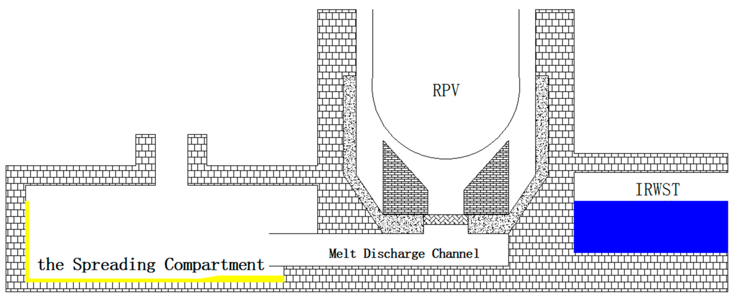
EPR is designed and developed by Framatome (now Areva NP) and Électricité de France (EDF) in France, and Siemens in Germany. The EVR design of EPR is reported by Fischer [8]. As shown in Figure 2, this EVCC mainly consists of three parts, namely as a specially designed reactor cavity with a melt plug, a melt discharge channel and a spreading compartment. After the failure of RPV, the corium is temporarily collected in the reactor cavity for a couple of hours at first, to eliminate effects on melt composition in different accident scenarios. Then the corium is transferred through a short melt discharge channel to a large room, i.e. the spreading compartment. Finally, after spreading on the ground, the corium is cooled by underground channel-cooling system and water flooding. Fischer etc. [18] prove that the channel-cooling system has an excellent performance of heat transfer, which can deal with a heat flux of more than 120kW/m2, by a 1:1 scaled test channel. Bouteille etc. [19] summarize the results of the Level 2 PSA and give the main results of the evaluation of the radiological consequences of core melt on the environment as 9E-8 per year.

2.3. ESBWR

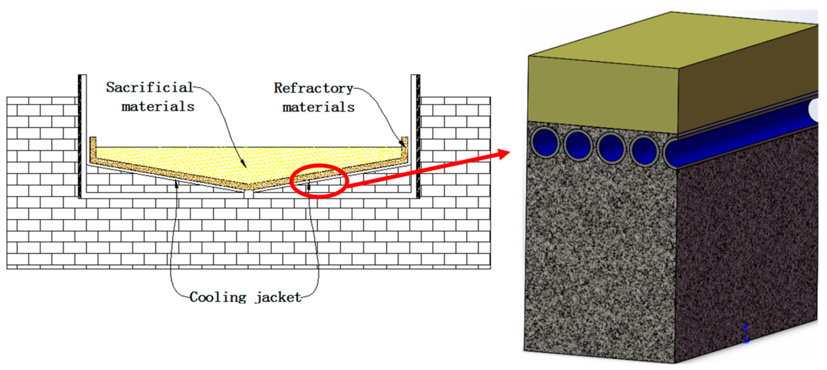
The Economic Simplified Boiling Water Reactor (ESBWR) is a passively safe generation III+ reactor designed by GE Hitachi Nuclear Energy (GEH), in which a core-catcher named as BiMAC (the Basemat-internal Melt Arrest and Coolability) has been introduced on the bottom of reactor cavity [11]. A vertical cross sectional view of BiMAC is shown in Figure 3. A container (about 11.2m in diameter and 2m high) with a cone-shaped bottom whose boundary is made by a series of side-by-side placed pipes, i.e. the so-called cooling jacket, is used to confine the corium released from RPV. In order to maintain the integrity of the container, a 20cm thick layer of refractory material is laid on the inside of the container. A lot of sacrificial materials are arranged in the container over the refractory materials.
The cooling jacket is designed to cool the refractory materials to ensure the corium will be confined in the container effectively. Then the corium will form a debris bed in BiMAC and then be cooled down by flooding water that overflows from pipes. The retention zone, shown as the center area in cross-section of the container, is designed as significantly large (to ensure the spreading area of more than 0.02m2/MWe) to meet the criterion of Advanced Light Water Reactor Utility Requirements Document [20].

2.4. EU-APR1400

EU-APR1400, the 1400 MWe Advanced PWR designed by the Korea Electric Power Corporation (KEPCO), with EVR strategy [10] is proposed to European market instead of the original one APR-1400 with IVR design. As shown in Figure 4, the core-catcher designed in EU-APR1400 is briefly similar with BiMAC, consisting of three parts which are integral metal catcher that is covered by a sacrificial layer, declining cooling channels and an injection system. The shape of the carbon steel-made catcher is rectangular (about 6m wide, 16m long and 1.5m high), and the shape of the cross section is “V” type with a 10-degree inclination angle. The cooling channels in core catcher of EU-APR1400 are some gaps between elevated core-catcher and wall of reactor cavity. Under severe accident conditions, coolant is supplied through the distributor under the catcher from the storage tank by gravity, then turns up into gaps to cool down the catcher and finally rises over the catcher to flood the molten pool inside. In this way, corium debris gets stable cooling and long-term retention. Rhee etc. [21] and Park etc. [22] evaluate the two-phase natural circulation flow in cooling channels of the ex-vessel core-catcher for EU-APR1400 and present how the diameter of pipe system impacts natural circulation then conclude that oscillatory flow exists in circulation.

2.5. APWR

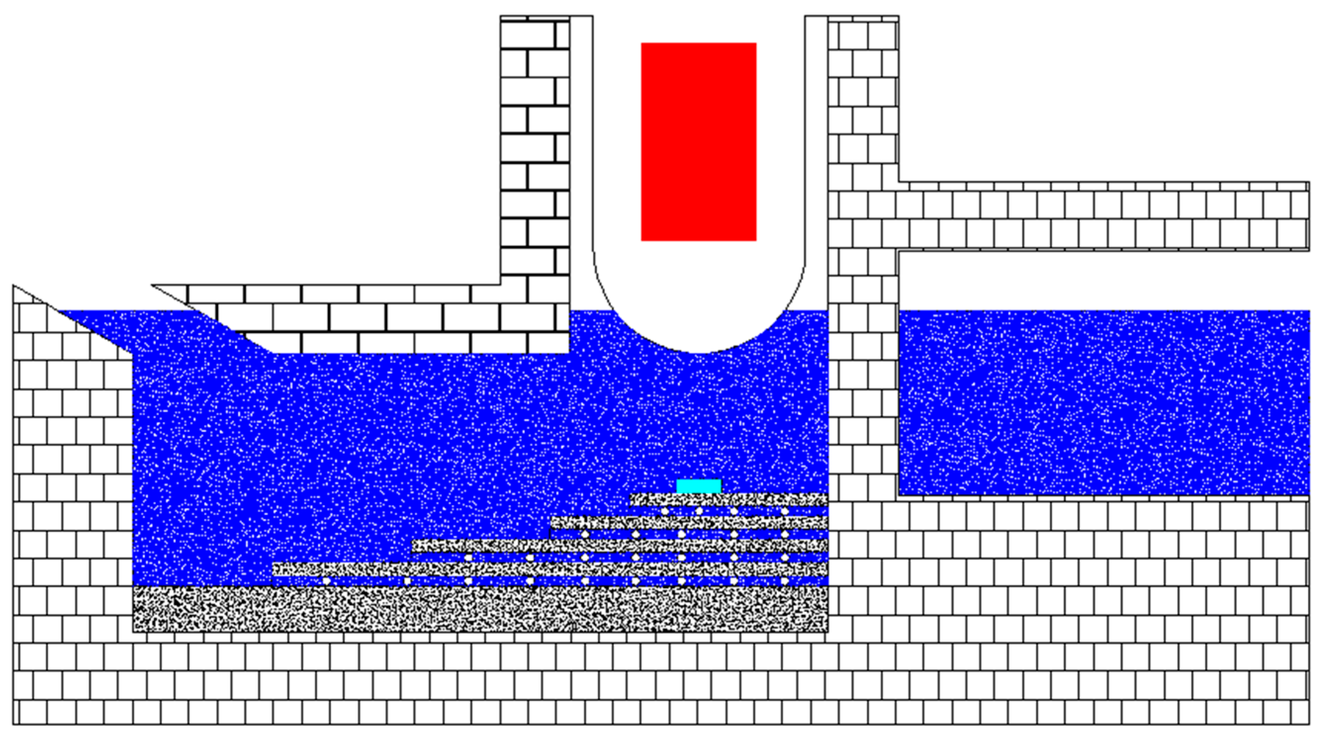
The advanced PWR (APWR) is a large capacity (electric output 1538MWe) Generation III four-loop PWR, which has been developed, as a nuclear power plant for future use in Japan, as a joint international cooperative development project by seven companies, including Mitsubishi Heavy Industries and Westinghouse [12]. Afterwards, two enhanced versions (electric output 1700MWe), US-APWR and EU-APWR, are designed based on APWR. A concept of wet reactor cavity named as MHI core-catcher is shared by all these versions for debris cooling for mitigating severe accidents, as shown in Figure 5. The reactor cavity is supposed to be filled with coolant water before the failure of RPV and a coolable debris bed will be formed on the reactor cavity floor which is covered with about 1-meter-thick concrete. The safety target of effectually confining the core melt is ensured by 1) high reliable reactor cavity flooding system which affords adequate coolant for melt cooling, 2) appropriate reactor cavity depth which equals to or greater than 6m for enhancing melt breaking-up and debris bed formation during the process of melt diving into cooling pool, and 3) sufficient spreading area which equals to or greater than 90m2 on reactor cavity floor to induce enough heat transfer area between the debris and the coolant. The risk of ex-vessel steam explosion is overcome by a well-designed containment structure which can withstand a high-level pressure load.

3. Pros and Cons of EVR Measures

This is to discuss the features of the above mentioned EVR measures adopted in the LWR designs, focusing on the comparisons with IVR and with the others among themselves.

3.1. EVR versus IVR

The comparison between the EVR and IVR measures primarily focuses on two aspects: the coolability of the corium and their respective applicable conditions.
In the IVR measures, after the corium migrates to the lower head of the RPV, it goes through three stages [23]: debris bed formation (it is assumed in the design that there is a high probability of water present in the lower head, where the corium interacts with water upon entry, fragmenting and forming a debris bed), debris bed remelting (due to the lack of continuous external water supply, the water in the lower head of the RPV will continuously evaporate under the influence of decay heat. Once the water is completely evaporated, the oxide melt will continue to heat up because of decay heat, melt the lower melting point metal components and eventually melt itself to form a melt pool), and stratified melt pool (during the remelting of the debris bed, complex physical and chemical reactions occur, which affect the final shape of the melt pool and, consequently, the distribution of heat flux density applied to the inner wall of the lower head of the RPV [24]). Currently, the effectiveness of the IVR measures is confirmed by comparing the critical heat flux (CHF) of the external cooling of the lower head of the RPV and the heat flux density applied to the inner wall of the lower head of the RPV.
A significant amount of optimization research has been conducted on the external cooling of the lower head of the RPV. For instance, in the design of APR1400, the CHF is increased by introducing wedge-shaped blocks in the flow channel to enhance natural circulation flow speed [25]. From the current experimental and computational analysis, the IVR measures’ coping limit is the 1400MWe reactor type without injecting water into the lower head of the RPV. The main uncertainty of the IVR measures comes from the estimation of the heat flux density applied to the inner wall of the lower head of the RPV by the corium. Currently, in engineering design, only the so-called envelope condition (i.e., the double-layer melt pool, composed of the upper metal melt and the lower oxide melt) is considered for the heat flux density applied to the inner wall of the lower head by the corium. However, considering that during the remelting process of the debris bed, the metal melts before the oxide, it may flow through the gaps of the debris bed to the edge wall position of the lower head of the RPV, forming a thinner metal layer, generating a more intense heat focusing effect, and even leading to premature failure of the lower head of the RPV [26]. Moreover, due to an insufficient understanding of the melt pool evolution process, there is still controversy over whether there is a more severe three-layer melt pool than the existing envelope condition.
In the EVR measures, cooling of the corium can be achieved in various ways. Direct contact cooling includes using sacrificial materials to interact with the core melt to significantly reduce its sensible heat (calculations for the VVER-CC show that corium at 2500°C can be rapidly reduced to 2150°C [27]), while also eliminating the threat of heat focusing effects by oxidizing the metal in the corium. Additionally, the heat load on the core catcher structural components is reduced by lowering the decay heat volumetric power density through phase mixing with the corium. Direct contact cooling also includes the interaction between the corium and cooling water formed by water injection at the top of the melt pool, which not only removes decay heat through boiling heat transfer but also effectively blocks the release of aerosols. The COMET concept, which is not used in engineering schemes, significantly enhances the cooling of the corium through direct contact by injecting water at the bottom of the melt pool, with an estimated heat transfer capacity of up to 3MW/m² [28]. In the EVR measures, there is also an indirect cooling method similar to the IVR measures, such as the heat exchanger of the VVER-CC, and the channel-type cooling unit of the EPR-CC. However, compared with the IVR measures, the EVR measures cool the corium in a collection container located outside the RPV, and the heat exchange area is usually larger than that of the lower head of the RPV, especially in the EPR-CC with a large spread of corium, where the heat exchange area is much larger than that of the lower head of the RPV. Therefore, the indirect cooling capacity of the EVR measures is stronger than that of the IVR measures.
In the IVR measures, continuous cooling needs to be provided externally to the lower head of the RPV. In the AP1000, due to the lower elevation of the RPV, submersion of the lower head of the RPV can be achieved by injecting water into the reactor cavity (from the IRWST), and the water formed by the containment condensation will also flow back into the reactor cavity, thereby achieving long-term cooling of the lower head of the RPV. Therefore, the implementation of the IVR strategy has a smaller impact on the containment layout, but the power level of the reactor type that it can cope with is relatively low, and there is no reactor type exceeding 1400MWe internationally that uses the IVR measures to cope with severe accidents.
In contrast, the EVR measures are suitable for higher power reactor types because of the stronger cooling capacity for the corium. However, the EVR measures require a larger layout space to arrange a collection container for the corium outside the RPV in the containment. For core catchers similar to the EPR, a dedicated spreading space needs to be set up. Therefore, the implementation of the EVR measures has a greater impact on the containment layout, but the measures can cope with severe accidents of higher power level reactor types.

3.2. Comparisons of EVR Measures

The comparison between the aforementioned EVR schemes primarily focuses on two aspects: the collection method of the corium and the cooling capability for the corium.
In the VVER-CC, the corium melts through the lower head of the RPV and enters the reactor cavity. Guided by the lower plate, it melts through the center baffle at the core location and falls into the basket below, where it interacts with sacrificial materials. To facilitate the smooth transfer of the melt into the basket, the surface of the lower plate is covered with iron oxide powder, which acts as a lubricant. The transfer process of the melt is relatively rapid, and the main reliance is on gravity, which ensures a higher reliability. The transfer methods of ESBWR and EU-APR1400 are similar to VVER, also relying on gravity to directly enter the core catcher, and are also highly reliable. However, there is a risk of inducing a steam explosion due to the early injection of cooling water during the transfer process in ESBWR and EU-APR1400. Although the VVER core catcher also has water injection at the top of the melt pool, the amount of water injected is small and the pool depth is shallow, making steam explosions less likely.
In the EPR-CC, the corium is retained in the reactor cavity for a certain period to ensure that all fuel assemblies and internal structures are completely melted, thus eliminating the impact of different accident scenarios and the composition of the melt. Although this strategy reduces the difficulty of subsequent analysis, the prolonged retention of the corium in the reactor cavity may lead to two potential risks: the long-term radiation heat transfer of high-temperature melt may cause the failure of the concrete structure of the reactor cavity (concrete structures are considered to have no mechanical strength above 500°C [29]), and the erosion of the sacrificial materials and the concrete of the reactor cavity by the high-temperature melt may lead to the premature failure of the structure.
In the APWR-CC, after the corium melts through the lower head of the RPV, it directly falls into a water pool. The transfer process of the melt is the shortest. However, the interaction between the corium and water may induce a steam explosion, leading to the splashing of the corium and not all of it is retained in the reactor cavity as expected.
In terms of cooling the corium, the EPR-CC greatly increases the heat exchange area by spreading the melt over a large area. At the same time, it cools the melt through the channel-type cooling units at the bottom and water injection at the top of the melt pool. The cooling capability is extremely strong, and it only takes a few days to solidify the melt. The VVER-CC mainly cools the melt with external cooling water through the heat exchanger, and the shallow water layer covering the top of the melt pool can also remove some heat. However, considering the smaller total heat exchange area and the poor thermal conductivity of the crust formed by the solidified melt, the VVER-CC has a relatively poor cooling capability for the melt, requiring nearly several months for the highest temperature of the melt to drop below 1600°C [27]. ESBWR, EU-APR1400, and APWR mainly rely on the cooling water covering the top of the melt pool to cool the melt (the inner surface of the container of ESBWR-CC is covered with about 200mm thick refractory material, and the cooling jacket mainly ensures the integrity of the container, with poor heat exchange capability for the melt. APWR-CC mainly relies on a thicker concrete layer to resist the erosion of the melt, and the heat exchange capability is also poor), but considering the larger spread area of the melt, overall, the cooling capability for the melt is stronger than that of the VVER core catcher and weaker than that of the EPR core catcher.

4. Remaining Issues and Uncertainties

Throughout the entire process of implementing IVR measures, the corium is always confined within the lower head of the RPV, and the available surface for cooling is merely the outer surface of the RPV’s lower head. The boundaries of the relevant research are relatively clear. In comparison, although the key concept of EVR measures is to transfer the corium to a pre-designed collection container for further cooling, the external environment and the structural form of EVR measures for different reactor types vary greatly, and the remaining issues need to be discussed separately.

4.1. Dry Reactor Cavity

In the existing EVR measures, most design schemes require implementation in a dry reactor cavity, that is, when the corium flows out from the lower head of the RPV, the reactor cavity is dry, or at least not containing a large amount of water. This can avoid steam explosions, thereby introducing significant uncertainty.
Under dry reactor cavity conditions, the focus of subsequent research should concentrate on the interaction between the corium and sacrificial materials, as well as more efficient heat transfer methods for the corium.
The interaction between the corium and sacrificial materials is crucial [30]. When the corium flows out from the lower head of the RPV, its temperature is extremely high. Direct contact with the boundaries of the core catcher would result in a significant thermal load due to the rapid release of sensible heat, potentially causing the core catcher to fail prematurely [31]. Therefore, in the current core catcher designs, sacrificial materials are used to interact with fresh core melt to reduce its temperature and get through the initial dangerous phase. Different core catcher of reactors use different sacrificial materials, with slightly different functions, but the basic requirements include: 1) the ability to maintain mechanical strength and chemical stability for a long time, 2) rapid melting upon contact with the corium to reduce its temperature by a large heat capacity and high lalent heat of fusion, 3) the ability to oxidize active metals carried by the corium, reducing the production of hydrogen [32], 4) to guarantee the core melt subcriticality in the core catcher by addition of specific neutron absorber material. The development process of EVR measures for different reactor types requires the development of applicable sacrificial materials based on actual needs, such as reducing non-condensable gases, and flammable gases produced during the interaction process between the corium and sacrificial materials, and optimizing the physical properties of the mixture after mixing with the corium (such as density inversion between the metal layer and the oxide layer to avoid the water-metal interaction when the water is delivered onto the top). New sacrificial material with lower action temperature such as SrFe12O19 was under investigation [33,34] which seems to be an essential view of research up to now.
In all current core catcher designs, top water injection is utilized to enhance heat transfer to the molten core material. The top water injection method is affected by the crust at the top of the melt pool, and the heat transfer efficiency is not high. However, the crust at the top of the melt pool is influenced by factors such as the composition of the melt, the size of the melt pool, the interaction between the melt and sacrificial materials, and the depth of the top water pool, resulting in local eruptions, and even local collapses, which can enhance the cooling capacity of the top water injection. This requires research based on different EVR measure design schemes and reactor parameters.
The ESBWR-CC and EU-APR1400-CC both enhance natural circulation flow by connecting the water pool above the melt pool with the cooling channel injection port through a specially designed structure, thereby enhancing heat transfer. The EPR-CC has a channel-cooling system laid at the bottom of the spreading compartment, and even if the top of a cooling channel unit is strongly heated, at high heat fluxes, a local dry-out occurred at the top of the channel, structural temperature remained in a safe range [18]. Apart from the bottom and surface, heat can even transfer to the side walls of the channel, resulting in a very good heat removing ability. In conclusion, heat transfer can be enhanced by optimizing the structure of heat exchange devices. The EPR-CC has adopted the approach of increasing the heat transfer area, while the ESBWR-CC and EU-APR1400-CC have employed methods that enhance the heat transfer coefficient.
The COMET concept [35] proposed by FZK injects water at the bottom of the melt pool, using the intense heat transfer formed by the direct contact of the melt and water to form a porous medium-like cooling flow channel inside the melt pool, greatly increasing the heat transfer area and achieving a tremendous heat transfer efficiency. A COMET concept catcher design applicable to the EPR has been developed, and relevant experimental studies have been conducted [36,37,38]. Experimental research on the CometPC revealed that the bottom water injection process generates a large amount of steam, demonstrating an extremely efficient cooling capacity. Even with an increase in the water injection rate, no steam explosion phenomenon occurred, indicating that cooling via bottom water injection is a particularly effective method for quenching the melt. Based on the COMET bottom water injection concept, the CEA conducted the VULCANO VW-U series of experiments, validating the WABE-COMET model. The results presented further support the application of the COMET concept [39].

4.2. Wet Reactor Cavity

A wet reactor cavity refers to the situation where there is a deep pool of water in the reactor cavity or core catcher when a large mass of corium flows out from the lower head of the RPV, such as the process in the APWR-CC and the Nordic BWR in the response to severe accidents. In addition, after the Fukushima accident, due to the emphasis on the threat of severe accidents, many early reactor types that did not originally have severe accident mitigation measures need to be simply modified to cope with severe accidents, and using a reactor cavity with a large amount of water for the retention of corium is the most direct choice.
In the case of a wet reactor cavity, steam explosions are the first issue that needs to be addressed. The threats of steam explosions include:
1)
The pressure pulse formed by the steam explosion damages the structure of the reactor cavity or core catcher, causing the core melt retention device to fail prematurely, and the transfer of the corium is uncontrolled.
2)
Damage to the containment structure, such as the pressure pulse formed by the steam explosion may cause the melt to splash or other ejected objects, all of which can threaten the integrity of the containment. In addition, significant displacement of some equipment (such as the collapse of the equipment support structure or direct impact by the pressure pulse) can exert a large pulling force on the pipelines connected to it, which may damage the integrity of the containment through the pipelines that penetrate the containment wall, leading to the release of radioactive materials.
Steam explosion is a complex process involving multiple fluids, multiple phases, and multiple time scales. To explore the factors affecting steam explosions, scholars usually decouple and study them through experimental control, modeling the flow of the melt, the interaction between the melt and the coolant, the vaporization of the coolant, the motion of the gas film, etc., and then interpreting and verifying them with coupled experiments. However, there is currently no unified understanding of the triggering mechanism, probability, and energy conversion rate of steam explosions. Currently, in experiments conducted with prototype materials (a mixture of UO2 and ZrO2), such as in the KROTOS [40] and FARO [41] experiments, spontaneous steam explosions have not occurred. However, during experiments in the TROI [42] steam explosions occurred on multiple occasions. Steam explosions have also frequently occurred in related experiments conducted with simulate material on VULCAN [43]. Consequently, in engineering design, when there is a risk of steam explosion, it is typically considered as a probable event, and reinforcement measures are taken to withstand such explosions. Some institutions are researching methods to mitigate or even eliminate steam explosions by adding substances to the water, such as increasing the coolant’s viscosity or altering the surface tension to stabilize the vapor film and suppress steam explosions [44,45,46,47,48]; or by introducing innovative ideas like adding suspended spheres in the water pool to restrict the disintegration of the melt jet, thereby suppressing steam explosions. There are also methods involving the use of water-absorbent spheres in combination with a sodium bicarbonate solution to weaken the steam explosion phenomenon [49].
In addition, when the spread area in the reactor cavity or the core catcher is relatively small, the retention process of corium also involves the formation of debris beds, the coolability of debris beds, and the interaction process between the core melt and concrete.
The dry-out heat flux (DHF) is considered as a key parameter for assessing the coolability of debris beds. There is a preliminary consensus that the coolability of debris beds is mainly influenced by the porous structure (i.e., the morphology of the debris bed) and the cooling method (i.e., the way in which cooling water is injected, such as top injection, bottom injection, and lateral injection). By analyzing the resistance of two-phase flow under the porous structure and DHF, one can grasp the flow and heat transfer characteristics of the debris bed, thereby analyzing its coolability. Early related studies mostly took a one-dimensional homogeneous spherical bed as the research object, simulating a simple debris bed structure, and obtained DHF for different experimental bed sizes, particle sizes, and particle shapes through experimental studies. However, due to the influence of factors such as particle shape and container size, the DHF obtained from different studies under approximate conditions varied greatly, and the experimental data were quite scattered [50,51]. Experiments on flow resistance in homogeneous and layered structured particle accumulation beds were also conducted by the DEBECO [52], showing that existing particle accumulation bed models can only describe the resistance characteristics in a single direction. It is necessary to conduct research on the flow resistance of non-spherical particles and mixed accumulation beds of particles of various sizes to understand the multi-dimensional two-phase flow and heat transfer mechanisms within porous structures. In addition to the structural characteristics of the debris bed itself, the method of water injection during the cooling process of the debris bed also affects the two-phase flow resistance and DHF of the debris bed, influencing its coolability. The University of Stuttgart in Germany has built the DEBRIS [53] to study the flow and heat transfer characteristics and dryout features within a spherical particle bed. The VTT Technical Research Centre of Finland has built the STYX and studied the dryout characteristics under downcomer design and top flooding conditions within mixed paticle size debris bed [54]. Yang Shengxing et al. [55] built a one-dimensional cylindrical mixed particle size sandstone debris bed and studied the impact of different water injection methods such as top flooding, natural circulation-driven bottom water injection, and peripheral water injection on DHF.
Meanwhile, the morphology of the debris bed has a direct impact on the subsequent coolability of the debris bed. Debris beds typically consist of large blocky structures, such as the cake-like debris bed observed in the FARO experiment (where the mass reached 50% of the total amount of the melt [56]), and debris with different particle size distributions. Further experimental studies on the formation of debris beds are needed to obtain more detailed results on the accumulation structure, shape, and particle size distribution of debris, in order to more accurately capture the two-phase flow and heat transfer characteristics within the debris bed. Furthermore, previous research on the formation of debris beds and their coolability was carried out independently. To better understand this process, joint experiments can be considered.
When the debris bed cannot be cooled, it will continue to interact with the concrete in the reactor cavity. Since the 1970s, a series of experiments on Melt Coolability and Con-crete Interactions (MCCI) have been conducted internationally, such as ACE/MACE [57,58], SURC [59,60], COMET-L [61,62], VULCANO [63], etc. These studies have successively investigated the effects of melt composition, type of con-crete, decay heat power, and the timing of water injection in flooded cavity and the cooling capacity of the melt. Due to the high temperatures of core melt, the main parameters measured in the experiments included the melt temperature and the ablation velocity of concrete. For the flooded cavity experiments, the debris/water heat flux was also estimated based on the rate of steam generated by the interaction.
Existing experimental results indicate an overall trend of decreasing melt tempera-ture and increasing heat transfer surface area as the melt erodes the concrete. Results adopting prototype material show that the concrete erosion of oxidic core melt is influ-enced by the type of concrete: For limestone concrete, the radial to axial erosion rate and ablation depth are approximately 1:1; whereas for siliceous concrete, it is about 3:1. Large-scale experimental results also show no significant effect on the erosion characteris-tics of siliceous concrete. It is currently believed that the interfacial properties of the inter-action between the melt and the two types of concrete are distinctly different.
The presence of metallic materials such as zirconium(Zr) and iron in the melt or con-crete has a thermal-hydraulic impact on the MCCI. The results have shown that the oxida-tion reaction between Zr and the decomposition gases of the concrete (CO2, H2O) leads to a transient exothermic reaction that can raise the melt temperature within tens of minutes. The heat transfer at the metal melt-concrete interface is enhanced compared to the ox-ide-concrete interface. However, the database for metal melt-concrete is limited, and there is no clear understanding of the phenomenological behavior in such cases.
The OECD-NEA’s 2017 report, "State-of-the-Art Report on Molten Corium Concrete Interaction and Ex-Vessel Molten Core Coolability," [64] points out that current experimental and theoretical research still has some deficiencies. There is a lack of research on the severe accident phenomenon of MCCI at the scale of the reactor cavity and the long-term effects of the melt, which may affect the effectiveness of existing nuclear power plant severe accident management guidelines.
Aside from the uncertainties in the initial conditions of MCCI brought by the core degradation and the failure process of the reactor pressure vessel, the residual uncertain-ties in the MCCI process mainly come from:
1)
Due to the lack of a more robust phenomenological model to rationalize the observed differences in erosion behavior between the two types of concrete used in experiments, there is still some uncertainty in extrapolating the results to prototype conditions.
2)
The simplicity on a well-mixed core melt pool in the presence of concrete decomposition gases contrasts with the complexity of the concrete ablation mechanism, in which the evolving melt-concrete interface gradually integrates into the melt. From a modeling perspective, this remains difficult to observe and capture through experiments.
3)
MCCI experiments conducted with prototype materials have relatively short durations. The Fukushima nuclear power plant accident has shown that longer transients are likely to occur, and it has been found in accident analysis that the termination of MCCI is significantly affected by the differences in melt pouring conditions predicted by different programs at the time of reactor vessel failure. These findings question the analytical results that predict long-term MCCI, especially in the presence of water. Therefore, if experimental data from short-duration experiments cannot be extrapolated to reactor conditions with high confidence, it is necessary to obtain experimental data from longer durations.
4)
The limitations of experimental techniques present significant challenges. The experiments are conducted under high-temperature (the actual experimental temperature of the core melt being around 2500K) condition, which substantially increases the difficulty of the experiments. This includes limitations in acquiring plenty of data, constraints on measurement accuracy, and the difficulty in estimating heat losses. Additionally, the experiments involve phenomena that are hard to quantify, such as material ejection and the positioning of the crust. However, inspections of the debris in the damaged Fukushima reactors may yield more data and information, thereby enhancing the understanding of the MCCI phenomena under conditions that are large-scale and fully prototypic. This would provide greater credibility for the application of simulation tools in existing power plants, offer a technical foundation for better containment design in future plans, and optimize the severe accident management strategies for both current and future plans.
5)
The MCCI under wet cavity conditions is even more complex.
Furthermore, to prevent the melting through of the reactor cavity bottom or the failure of the core catcher, it is usually necessary to increase the thickness of the concrete, or to add cooling to the concrete, which into slow down or terminate the erosion of the melt.

5. Concluding Remarks and Recommendations

This is to summarize the points which have been presented, and to recommend the future research needs and potential improvements in the EVR strategy.
EVR strategy is preferable to high power reactors. As an effective measure for mitigating severe accident scenarios, EVR strategy shows much robustness on melt retention and heat removing capability, thus, it performs high credit on the prevention of massive radioactive release.
Based on the summary and comparison presented above, we conclude some suggestions for the engineering design of EVR strategy:
1) If the corium container must be placed outside the reactor cavity (probably because the layout of reactor cavity is restricted or the corium container is space-costly), collecting and transferring the corium should be done as quickly as possible to reduce uncertainties that impact effectiveness of the melt retention.
2) Increasing surface-to-volume ration of the melt pool is an excellent means of heat transfer enhancement, which can significantly shorten the melt solidification time. Many options can be chosen, like spreading the melt layer thinner, holding the melt in an elongated cylinder-type container, distributing melt into several sub-containers, to create a porous structure inside the melt, and so on.
3) In order to abate the release of non-condensable gas and radioactive material, core-catcher designers should take into account that minimizing direct contact of melt metal and water/steam in order to reduce the generation of hydrogen, as far as possible to avoid MCCI, such as isolating the melt from containment structure concrete, or decreasing the usage of sacrificial material, and limiting exposure intensity of the melt to reduce fission products release.
4) Considering the post-accident clean-up operation, an EVR design should offer convenience for an engineering approach on the removal of corium and material with residual radiation.
After 2011, the Fukushima Daiichi nuclear disaster, safety issues of nuclear power plants attracted much attention with the pubic, and higher level of safety objects are required by authorities. On this background, the research on core retention measures with much creditable robustness and high safety margin against complex severe accident scenarios is commonly proposed in the globe. Development of EVR is especially motivated by the need of high power reactors in Europe and Asia. We believe the information summarized and conclusions in this context are helpful to future R&D needs.

References

  1. Kymäläinen, H. Tuomisto, T.G. Theofanous, In-vessel retention of corium at the Loviisa plant. Nucl. Eng. Des. 1997, 169, 109–130. [Google Scholar] [CrossRef]
  2. T. G. Theofanous, C. Liu, S. Additon, S. Angelini, O. Kymäläinen, T. Salmassia, In-vessel coolability and retention of a core melt. Nucl. Eng. Des. 1997, 169, 1–48. [Google Scholar] [CrossRef]
  3. Esmaili and M. Khatib-Rahbar, Analysis of in-vessel retention and ex-vessel fuel coolant interaction for AP1000, NUREG/CR-6849, ERI/NRC-04-201, August 2004.
  4. S. S. Lee, S.H. Kim, K.Y. Suh, The design features of the advanced power reactor 1400. Nucl. Eng. Technol. 2009, 41, 995–1004. [Google Scholar] [CrossRef]
  5. J. Xing, D.Y. Song, Y.X. Wu, HPR1000: Advanced pressurized water reactor with active and passive safety. Engineering 2016, 2, 79–87. [Google Scholar] [CrossRef]
  6. M. G. Zheng, J.Q. Yan, S.T. Jun, L. Tian, X.J. Wang, Z.M. Qiu, The general design and technology innovations of CAP1400. Engineering 2016, 2, 97–102. [Google Scholar]
  7. M. Fischer M, P. Levi, The severe accident control strategy of the KERENA BWR, Proc. of ICAPP ’10, San Diego, CA, USA, June 13-17, 2010.
  8. M. Fischer, The severe accident mitigation concept and the design measures for core melt retention of the European Pressurized Reactor. Nuclear Engineering and Design 2004, 230, 169–180. [Google Scholar] [CrossRef]
  9. V. Bezlepkin, I.V. Kukhtevich, Yu.G. Leont’ev, S. Bechta, The concept of overcoming severe accidents at nuclear power stations with VVER reactors. Thermal Engineering 2004, 51, 115–123. [Google Scholar]
  10. Jong Ho Lee, Ji Hwan Kim, Corium Retention and Cooling by an Ex-vessel Core-catcher for Nuclear Power Plants, Transactions of the Korean Nuclear Society Autumn Meeting Jeju, Korea, October 21-22, 2010.
  11. T. G. Theofanous, T.N. Dinh, Application of the risk-oriented accident analysis methodology to the economic, simplified boiling water reactor design. Multiphase Science and Technology 2008, 20, 88–211. [Google Scholar]
  12. H. Nojiri, Mitsubishi US-APWR and EU-APWR, IAEA Interregional Workshop on Advanced Nuclear Reactor Technology, Vienna, Austria, 4-8 Jul 2011.
  13. C. C. Chu, J.J. Sienicki, B.W. Spencer, W. Frid, G. Löwenhielm, Ex-vessel melt-coolant interactions in deep water pool: studies and accident management for Swedish BWRs. Nuclear Engineering and Design 1995, 155, 159–213. [Google Scholar] [CrossRef]
  14. W. M. Ma, T.N. Dinh, The effects of debris bed’s prototypical characteristics on corium coolability in a LWR severe accident. Nuclear Engineering and Design 2010, 240, 598–608. [Google Scholar] [CrossRef]
  15. W. M. Ma, Y.D. Yuan, B.R. Sehgal, In-vessel melt retention of pressurized water reactors: historical review and future research needs. Engineering 2016, 2, 103–111. [Google Scholar] [CrossRef]
  16. Gusaro, V.V. et al., Sacrificial materials for safety systems of nuclear power stations: a new class of functional materials. Thermal Engineering 2001, 9, 721–723. [Google Scholar]
  17. Sidorov, A.S. et al., The device for core melt localization at the Tyan’van nuclear power station with a VVER-1000 reactor. Thermal Engineering 2001, 9, 707–711. [Google Scholar]
  18. M. Fischer, O. Herbst, H. Schmidt, Demonstration of the heat removing capabilities of the EPR core catcher. Nuclear Engineering and Design 2005, 235, 1189–1200. [Google Scholar] [CrossRef]
  19. Bouteille, F. Azarian G., Bittermann D., et al., The EPR overall approach for severe accident mitigation. Nuclear Engineering and Design 2006, 236, 1464–1470. [Google Scholar] [CrossRef]
  20. ADVANCED LIGHT WATER REACTOR UTILITY REQUIREMENTS DOCUMENT,VOLUME III ALWR PASSIVE PLANT,Revision 8, Issued 3/99.
  21. B.W. Rhee, K.S. Ha, R.J. Park, J.H. Song, A scaling study of the natural circulation flow of the ex-vessel core catcher cooling system of EU-APR1400 for designing a scale-down test facility for design verification, Proc. of ICAPP’12, Chicago, USA, 2012.
  22. Rae-Joon Park, Kwang-Soon Ha, Bo-Wook Rhee, Hwan Yeol Kim, Detailed evaluation of two phase natural circulation flow in the cooling channel of the ex-vessel core catcher for EU-APR1400. Nuclear Engineering and Design 2016, 298, 33–40. [CrossRef]
  23. Sehgal, B.R. Nuclear safety of light water reactors: severe accident phenomenology. Waltham: Academic Press; 2012.
  24. Peng Yu, et al. An assessment of the lumped parameter model for the two-layer melt pool heat transfer. Annals of Nuclear Energy 2023, 180. [Google Scholar]
  25. Rempe JL, Suh KY, Cheung FB, Kim SB. In-vessel retention strategy for high power reactors. Idaho Falls: Idaho National Engineering and Environmental Laboratory; 2005 Jan. Report No.: INEEL/EXT-04-02561.
  26. Xiao Zeng, et al. A scoping study on remelting process of a debris bed in the lower head of reactor pressure vessel. Annals of Nuclear Energy 2023, 189. [Google Scholar]
  27. Vladimir Benzianovich Khabensky, et al., Severe accident management concept of the VVER-1000 and the justification of corium retention in a crucible-type core catcher, Nuclear Engineering and Technology, Vol.41, NO.5, June 2009. 20 June.
  28. Walter Widmann, Manfred Burger, Gunter Lohnert, Hans Alsmeyer, Walter Tromm, Experimental and theoretical investigations on the COMET concept for ex-vessel core melt retention. Nuclear Engineering and Design 2006, 236, 2304–2327. [CrossRef]
  29. ourneau, C., Piluso, P., Molten Core Concrete Interation. In Comprehensive Nuclear Materials; Konings, R.J., Ed.; 2012; Volume 2, pp. 635–654.
  30. Seiler, J.M. Froment K., Material effects on multiphase phenomena in late phases of severe accidents of nuclear reactor. Multiphase Science and Technology 2000, 12, 117–257. [Google Scholar] [CrossRef]
  31. P. P. Kulkarni, A.K. Nayak, Study on coolability of melt pool with different strategies. Nuclear Engineering and Design 2014, 270, 379–388. [Google Scholar] [CrossRef]
  32. V. V. Gusarov, V. I. Almjashev, V. B. Khabensky, S. V. Beshta, etc., Physicochemical Modeling and Analysis of the Interaction between a Core Melt of the Nuclear Reactor and a Sacrificial Material. Glass Physics and Chemistry 2005, 31, 53–66. [Google Scholar] [CrossRef]
  33. S. M. An, K.S. Ha, B.T. Min, H.Y. Kim, J.H. Song, Ablation characteristics of special concrete due to an impinging zirco-nium-dioxide melt jet. Nuclear Engineering and Design 2015, 284, 10–18. [Google Scholar] [CrossRef]
  34. Andrei, A. Komlev, Vyacheslav I.Almjashev, etc., New sacrifificial material for ex-vessel core catcher. Journal of Nucle-ar Materials 2015, 467, 778–784. [Google Scholar]
  35. W。 Tromm, H. Alsmeyer, Experiments for a core catcher concept based on water addition from below. Nuclear Engineering and Design 1995, 157, 437–445. [CrossRef]
  36. H. Alsmeyer, W. Tromm. The COMET Concept for Cooling Core Melts: Evaluation of the Experimental Studies and Use in the EPR, FZKA 6186, EXV-CSC(99)-D036[R]. 1999.
  37. H. Alsmeyer, T. Cron, G. Merkel, S. Schmidt-Stiefel, W. Tromm, T. Wenz. Melt Cooling by Bottom Flooding: The Experiments CometPC-H4 and -H5, FZKA 6945, SAM-ECOSTAR-D45[R]. 2004.
  38. S. Lomperski, M.T. Farmer, Performance testing of engineered corium cooling systems. Nuclear Engineering and Design 2012, 243, 311–320. [Google Scholar] [CrossRef]
  39. Ö. Yilmaz, G. Pohlner, M. Buck and J. Starflinger C. Journeau (2016), Design Considerations for a Core-Catcher Concept Based on Bottom-Flooding through Porous Concrete, NUTHOS-11[C].
  40. Huhtiniemi, I. Magallon, D. Insigh into steam explosion with corium melts in KROTOS. Nucl. Eng. Des. 2001, 204, 391–400. [Google Scholar] [CrossRef]
  41. Magallon, D. Huhtiniemi, I. Corium melt quenching tests at low pressure and subcooled water in FARO. Nucl. Eng. Des. 2001, 204, 369–376. [Google Scholar] [CrossRef]
  42. Kim, J.H., Park, I.K., Min, B.T., Hong, S.W., Shin, Y.S., Song, J.H., Kim, H.D. An experimental study on intermediate steam explosions experiments with molten zir-conia and corium in the TROI facilities. In: Proceedings of the 10th International Conference on Nuclear Thermal Hydraulics (NURETH-10), Seoul, Korea, 2003; pp. 1–6.
  43. Min J, Ma W, Zhu G,et al.An experimental study on steam explosion of a small melt jet falling into a water pool[J]. Nuclear engineering and design 2022, 391. [CrossRef]
  44. Kim, H. Single Droplet Vapor Explosion Experiments, The U. of Wisconsin - Madison, 1986.
  45. Nelson, L. and Guay, K.P., "Suppression of Steam Explosions in Tin and FeAl2O3 Melts by Increasing the Viscosity of the Coolant," High Temperature-High Pressures, Vol 18, 1986.
  46. Nelson, L. S. and Duda, P. M., "Steam Explosion Experiments with Single Drops of Iron Oxide Melted with a CO2 Laser. Part II. Parametric Studies," NUREG/CR-2718, SAND-82-1105 R3, Sandia National Laboratory, 1985.
  47. Becker, K.M. and Lindland, K.P., "The Effects of Surfactants on Hydrodynamic Fragmentation and Steam Explosions," KTH-NEL-50, Royal Institute of Technology, Stockholm, Sweden, 1991.
  48. Kowal, M.G. and Dowling, M.F. and Abdel-Khalik, S.I., "An Experimental Investigation of the Effects of Surfactants on the Severity of Vapor Explosions," Nucl. Sci. & Eng. Vol 115, pi 85—192, 1993.
  49. Manfred Fischer, Torsten Keim, Markus Hupp, Super Absorbing Polymers for the Mitigation of Ex-Vessel Core Melt Scenarios in Gen II Plants, Technical Meeting on Ex-Vessel Molten Corium Behaviour and Coolability 14.-17.06.2022.
  50. PATRICK S, MANFRED G, RUDI K. Basic investigations on debris cooling. Nuclear Engineering and Design 2006, 236, 2104–2116. [Google Scholar] [CrossRef]
  51. ZOU Xumao, LI Liangxing, KONG Liubo, et al. Two-phase flow resistance and interfacial drag in packed beds. J.Journal of shanghai jiao tong university 2017, 51, 470–475. [Google Scholar]
  52. ZHANG Zhengzheng, Li Liangxing, MA Weimin, et al. Investigaion on Flow Characteristics in Radial Stratified Debris Bed. Atomic Energy Science and Technology 2022, 56, 2032–2040. [Google Scholar]
  53. KULKARNI P P, RASHID M, KULENOVIC R, et al. Experimental investigation of coolability behaviour of irregularly shaped particulate debris bed[J]. Nuclear Engineering and Design 2010, 240, 3067–3077. [Google Scholar] [CrossRef]
  54. LI L X, ZOU X M, WANG H S, et al. Investigations on two-phase flow resistances and its model modifications in a packed bed[J]. International Journal of Multiphase Flow 2018, 101, 24–34. [Google Scholar] [CrossRef]
  55. Yang Shengxing, Gong Houjun, Fang Yu, et al. Experimental Study on Cooling Characteristics of Mixed Partical Size Debris Bed under Different Water Injection Methods. Nuclear Power Engineering 2023, 44, 247–252. [Google Scholar]
  56. Magallon D, Huhtiniemi I. Corium melt quenching tests at low pressure and subcooled water in FARO. Nucl Eng Design 2001, 204, 369–376. [Google Scholar] [CrossRef]
  57. D.H. Thompson, M.T. Farmer, J.K. Fink, D.R. Armstrong, B.W. Spencer, Compilation, analysis and interaction of ACE Phase C and MACE experimental data, Report ACEX TRC-14, Argonne National La-boratory, Chicago, IL, USA, 1997.
  58. M.T. Farmer, B.W. Spencer, D.J. Kilsdonk, W. Aeschlimann, Status of large scale MACE Core Coolability experiments, OECD Workshop on Ex-Vessel Debris Coolability, Karlsruhe, Germany (1999).
  59. E.R. Copus, Sustained Uranium dioxide Concrete interaction tests: The SURC test series,2nd OECD (NEA) Spec. Mtg. on Molten Core DebrisdConcrete Interactions, Karlsruhe,Germany (1992).
  60. E.R. Copus, R.E. E.R. Copus, R.E. Blose, J.E. Brockmann, R.B. Simpson, D.A. Lucero, Core-Concrete Interactions Using Molten Urania With Zirconium on a Limestone Concrete Basemat, The SURC-1 Experiment, Report NUREG/CR-5443, Sandia National Lab. (1992).
  61. E.R. Copus, R.E. E.R. Copus, R.E. Blose, J.E. Brockmann, R.B. Simpson, D.A. Lucero, Core-Concrete Interactions using Molten UO2 with Zirconium on a Basaltic Basemat: The SURC-2 Experiment, (1990) Sandia Nat. Lab. Report NUREG/CR-5564, SAND90–1022 (1990).
  62. E.R. Copus, R.E. E.R. Copus, R.E. Blose, J.E. Brockmann, R.D. Gomez, D.A. Lucero, Core-Concrete Interactions using Molten Steel with Zirconium on a Basaltic Basemat: The SURC-4 Experiment, In: NUREG/CR-4994, SAND87–2008, Sandia National Laboratories (1989).
  63. C. Journeau, P. C. Journeau, P. Piluso, J.F. Haquet, Behaviour of nuclear reactor pit concretes under severe accident conditions, Proc. CONSEC ’07, Concrete under Severe Conditions (2007). Tours, France.
  64. Fernando Robledo, Mitchel T. Farmer, Mitchel T. Farmer, Claus Spengler, Claus Spengler, Sudhamay Basu, State-of-the-Art Report on Molten Corium Concrete Interaction and Ex-Vessel Molten Core Coolability, NEA/CSNI/R(2016)15, 2017.
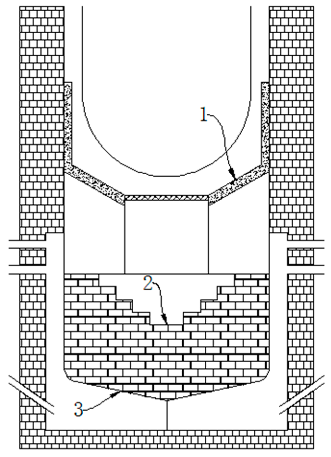
Figure 1. Ex-vessel catcher for the VVER-1000 reactor.
Preprints 119898 g001
Figure 2. Ex-vessel catcher for the EPR.
Preprints 119898 g002
Figure 3. Ex-vessel catcher for the ESBWR.
Preprints 119898 g003
Figure 4. Ex-vessel catcher for the EU-APR1400: (a) The cross-sectional view of the structure; (b) Top view of the spreading area.
Preprints 119898 g004
Figure 5. Ex-vessel catcher for the APWR.
Preprints 119898 g005
Disclaimer/Publisher’s Note: The statements, opinions and data contained in all publications are solely those of the individual author(s) and contributor(s) and not of MDPI and/or the editor(s). MDPI and/or the editor(s) disclaim responsibility for any injury to people or property resulting from any ideas, methods, instructions or products referred to in the content.
Copyright: This open access article is published under a Creative Commons CC BY 4.0 license, which permit the free download, distribution, and reuse, provided that the author and preprint are cited in any reuse.
Prerpints.org logo

Preprints.org is a free preprint server supported by MDPI in Basel, Switzerland.

Subscribe

© 2024 MDPI (Basel, Switzerland) unless otherwise stated