Submitted:
01 October 2024
Posted:
02 October 2024
You are already at the latest version
Abstract
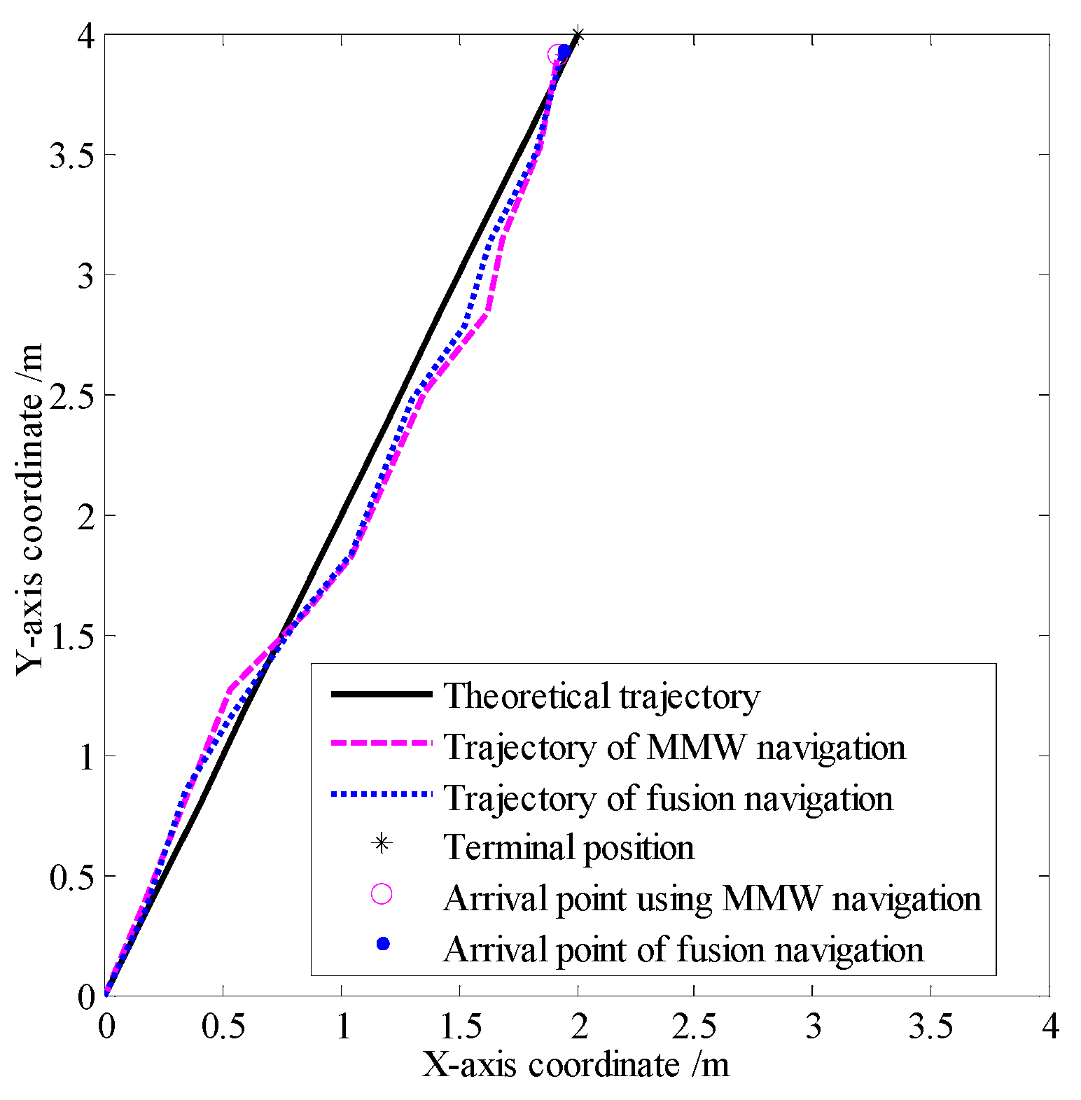
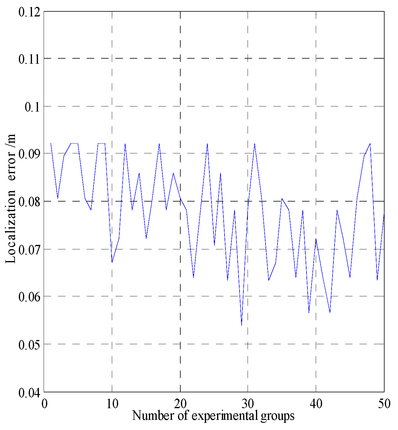
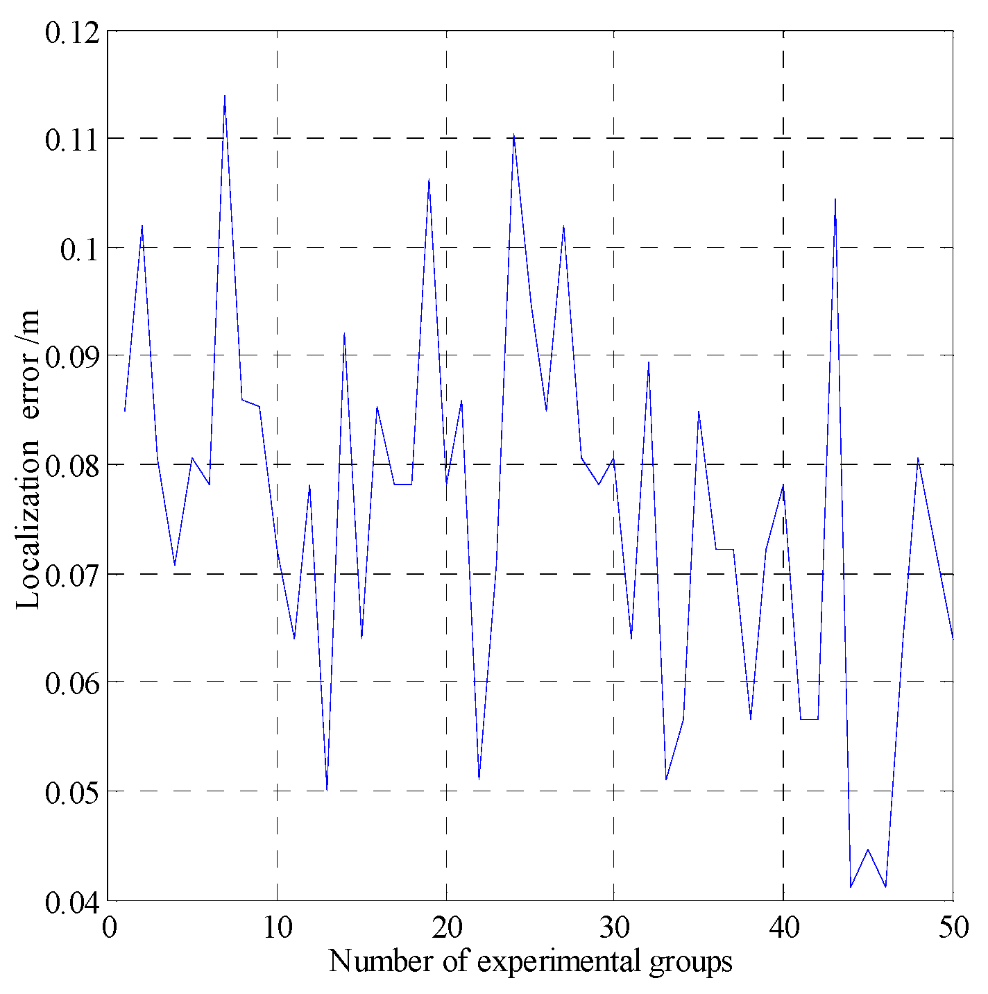
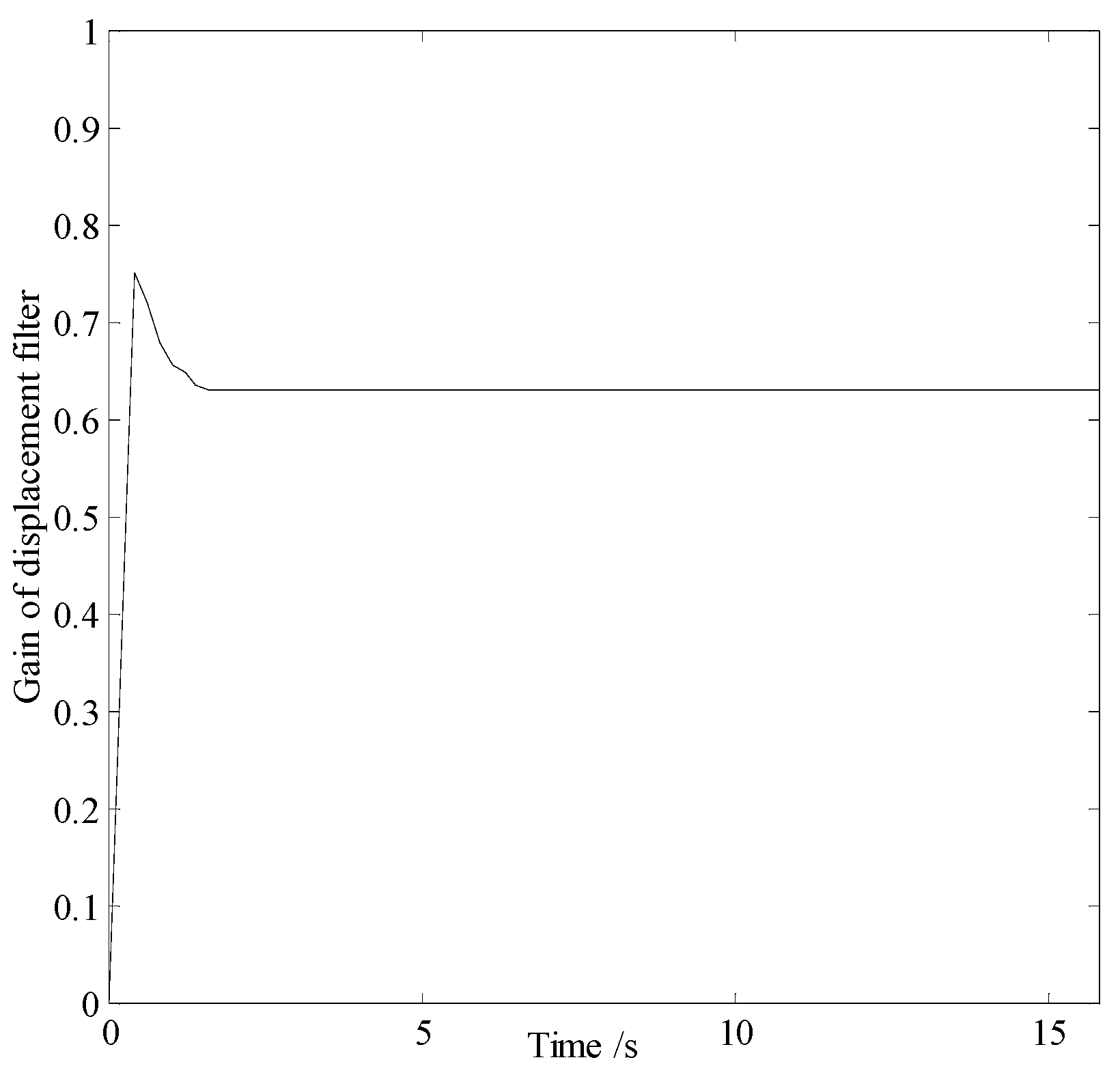
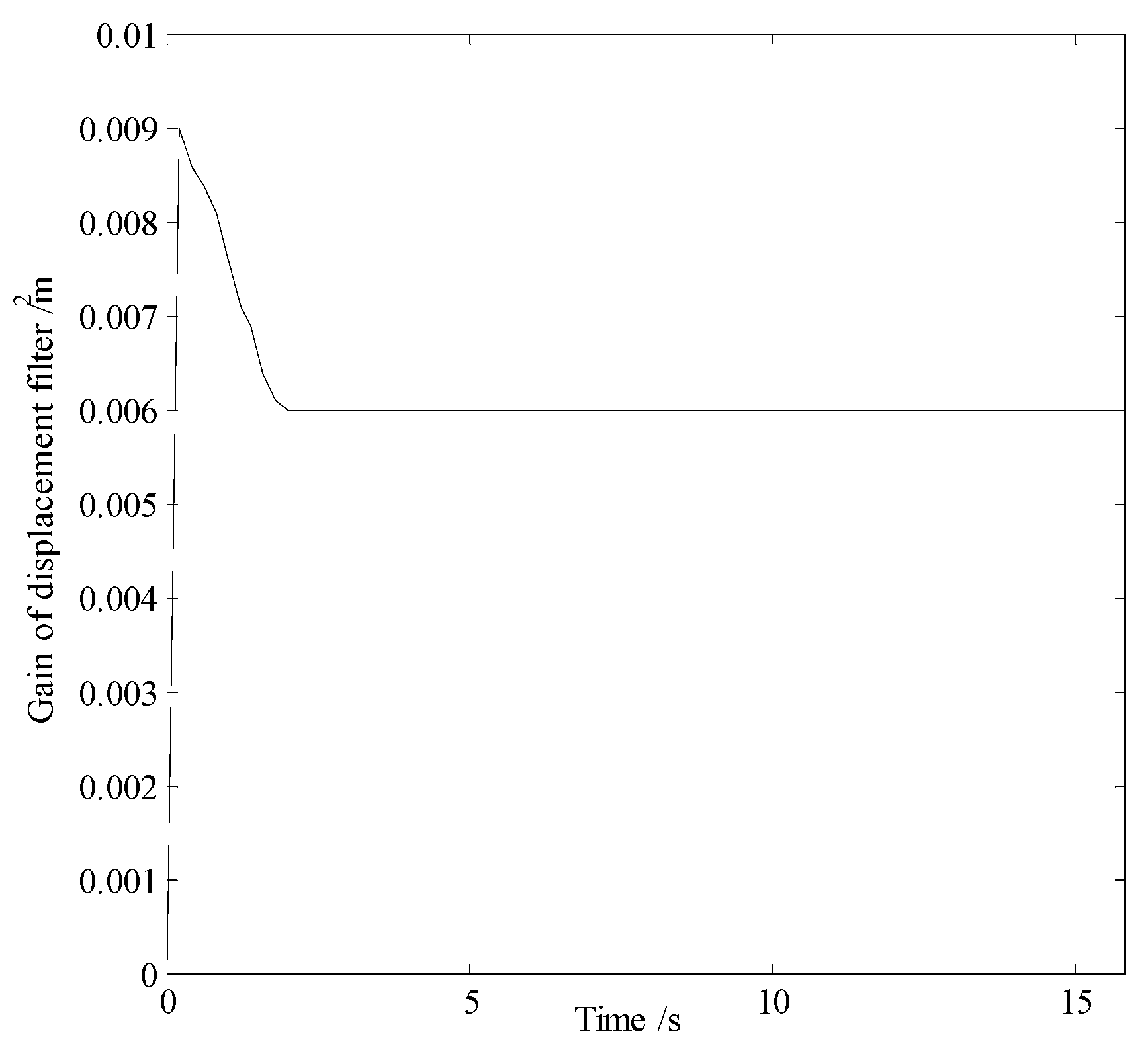
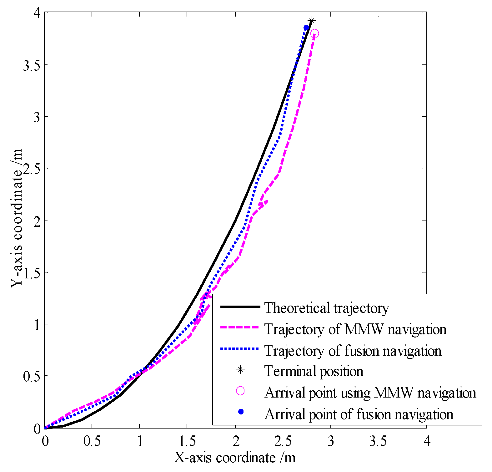
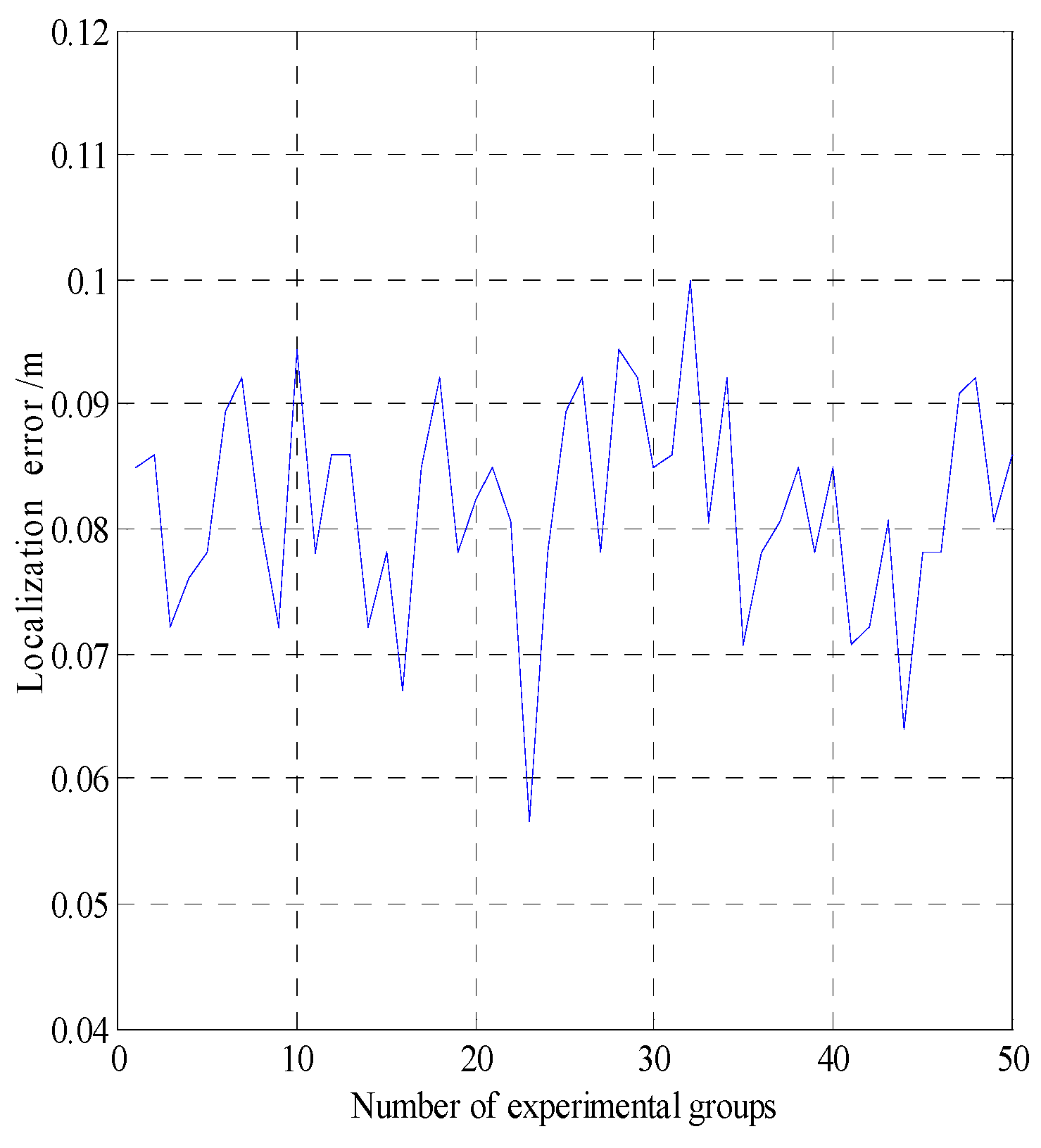
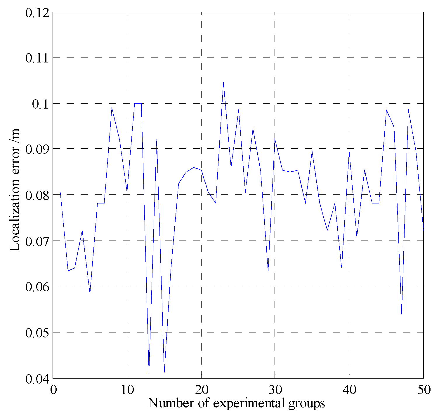
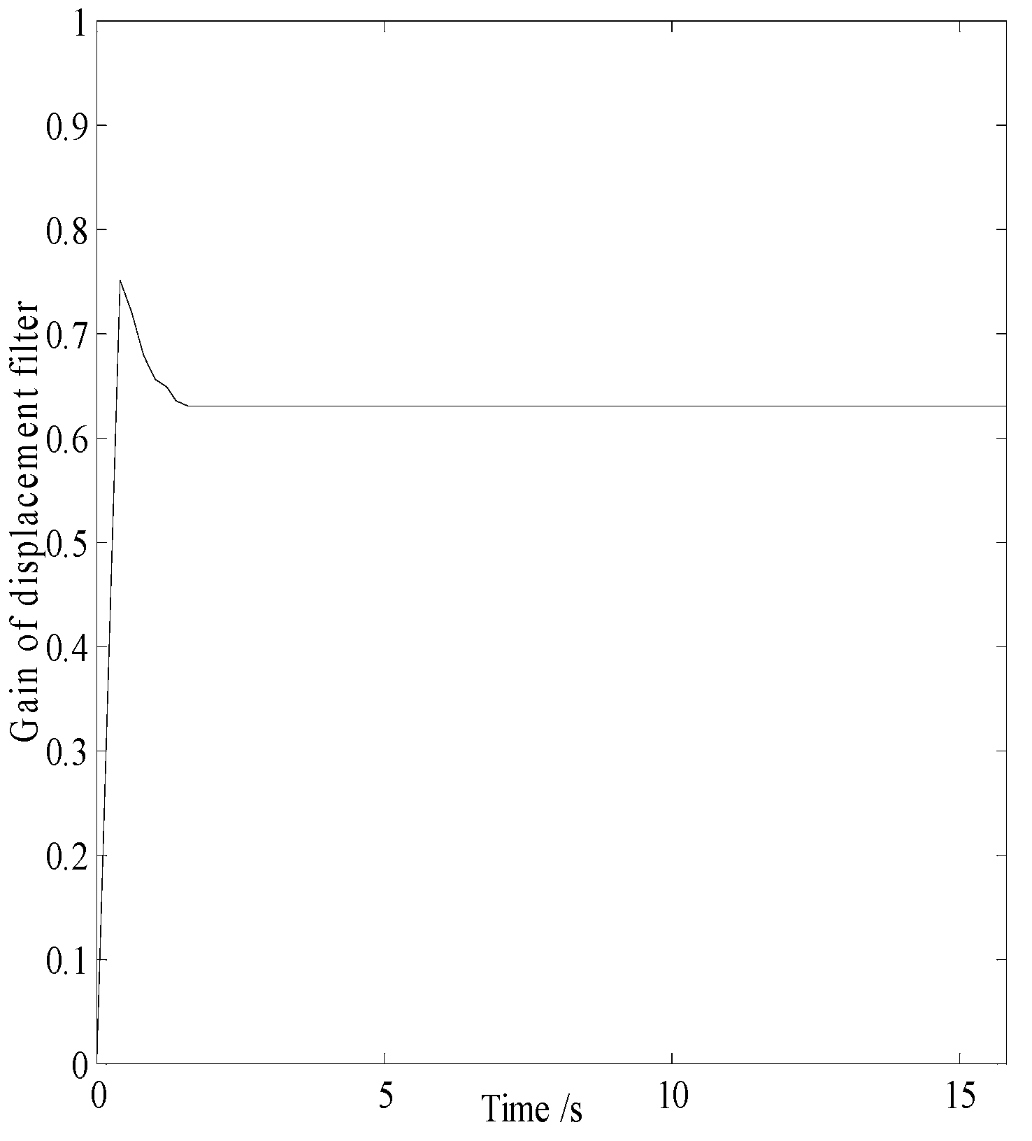
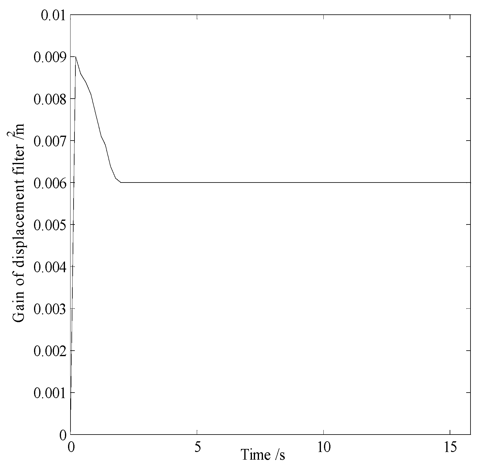
In smog and dust environments, vision and laser-based navigation methods can not be used effectively for controlling the movement of a robot. Autonomous operation of a security robot can be achieved in such environments by using millimeter wave (MMW) radar for the navigation system. In this study, an approximate center method under sparse point cloud is proposed, and a security robot navigation system based on millimeter wave radar is constructed. To improve the navigation accuracy of the robot, inertial navigation of the robot is integrated with MMW radar. Based on the concept of inertial navigation, the state equation for the motion principle of the robot is deduced. According to principle of MMW navigation, the measurement equation is derived, and the kinematics model of the robot is constructed. Further, by applying the Kalman filtering algorithm, a fusion navigation system of the robot based on MMW and inertial navigation is proposed. The experimental results show that the navigation error is close to the error of the navigation system with only MMW in the initial stage. With iterations of the filtering algorithm, the gain matrix converges gradually, and the error of the fusion navigation system decreases, leading to the stable operation of the robot. The localization error of the fusion navigation system is approximately 0.08 metre, and the navigation accuracy is better than that of the navigation system with only MMW radar.
Keywords:
1. Introduction
2. Design of Navigation System
2.1. MMW Navigation System
2.2. Strapdown Inertial Navigation System
3. Fusion Navigation System
3.1. State Equation
3.2. Measurement Equation
3.3. Noise
3.4. Filtering Algorithm
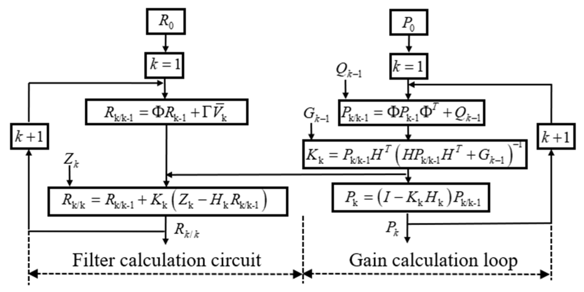
| Algorithm Integrated navigation using Kalman filter approach |
| 1: At k, the predicted position coordinate of the robot can be deduced as follows: |
| 2: The mean square error of the estimate is: , is the best estimation error covariance at k−1. |
| 3: The Kalman filter gain can be obtained: |
| 4: The optimal estimation position coordinate of the robot can be obtained as follows: |
| 5: The mean square error between the optimal estimated position coordinate and the true position coordinate is given by |
4. Experiment and Analysis
4.1. Experimental Equipment
4.2. Experimental Parameters
4.3. Experimental Results and Analysis
5. Conclusions
Acknowledgments
References
- C. G. Hobart et al., “Achieving Versatile Energy Efficiency With the WANDERER Biped Robot,” IEEE Trans. Robot. 36(3), 959-966. [CrossRef]
- Y. Chang et al., “LAMP 2.0: A Robust Multi-Robot SLAM System for Operation in Challenging Large-Scale Underground Environments,” IEEE Robot. Autom. Lett. 7(4), 9175-9182. [CrossRef]
- Z. Zhou et al., “Navigating Robots in Dynamic Environment With Deep Reinforcement Learning,” IEEE T INTELL TRANSP. 23(12), 25201-25211.
- Hu Dai, Rui Zheng, Xiaolu Ma, et al. Adaptive Tracking Strategy for the Positioning of Millimeter-wave Radar Security Robots. IEEE Sensors Journal, 2024, 24(13): 21321-21330 . [CrossRef]
- Q. Tao, Z. Hu, G. Lai, et al. SMLAD: Simultaneous Matching, Localization, and Detection for Intelligent Vehicle From LiDAR Map With Semantic Likelihood Model[J]. IEEE Transactions on Vehicular Technology, 2024, 73(2): 1857-1867.
- F. Penizzotto, E. Slawinski and V. Mut, “Laser Radar Based Autonomous Mobile Robot Guidance System for Olive Groves Navigation,” IEEE Lat. AM. Trans. 6(1), 191–198. [CrossRef]
- H. Bavle, J. L. Sanchez-Lopez, M. Shaheer, J. Civera and H. Voos, “Situational Graphs for Robot Navigation in Structured Indoor Environments,” IEEE Robotics and Automation Letters. 7(4), 9107-9114. [CrossRef]
- Q. Zou, Q. Sun, L. Chen, B. Nie and Q. Li, “A Comparative Analysis of LiDAR SLAM-Based Indoor Navigation for Autonomous Vehicles,” IEEE T INTELL TRANSP. 23(7), 6907-6921. [CrossRef]
- K. Lobos-Tsunekawa, F. Leiva and J. Ruiz-del-Solar, “Visual Navigation for Biped Humanoid Robots Using Deep Reinforcement Learning,” IEEE Robot. Autom. Lett. 3 (4), 3247–3254. [CrossRef]
- S. P. P. da Silva, J. S. Almeida, E. F. Ohata, J. J. P. C. Rodrigues, V.H. C. de Albuquerque and P. P. Rebouças Filho, “Monocular Vision Aided Depth Map from RGB Images to Estimate of Localization and Support to Navigation of Mobile Robots,” IEEE Sensors J. 20(20), 12040-12048. [CrossRef]
- M. Ijaz, Z. Ghassemlooy, J. Pesek, O. Fiser, H. Le Minh and E. Bentley, “Modeling of Fog and Smoke Attenuation in Free Space Optical Communications Link Under Controlled Laboratory Conditions,” Journal of Lightwave Technology. 31(11), 1720-1726. [CrossRef]
- Valada, J. Vertens, A. Dhall and W. Burgard, “AdapNet: Adaptive semantic segmentation in adverse environmental conditions,” 2017 IEEE International Conference on Robotics and Automation (ICRA) (IEEE, 2017) pp. 4644-4651.
- W. Li, R. Chen, Y. Wu et al. Indoor Positioning System Using a Single-Chip Millimeter Wave Radar[J]. IEEE Sensors Journal, 2023, 23(5): 5232-5242.
- “Environmental sensing using millimeter wave sensor for extreme conditions,” 2015 IEEE International Symposium on Safety, Security, and Rescue Robotics (SSRR) (IEEE, 2015) pp. 1-7.
- X Zh Chen et al., “Development of millimeter wave radar imaging and SLAM in underground coal mine environment,” Journal of China Coal Society. 45(6), 2182-2192.
- Rui Zheng, Fangdong Li, “Navigation system of security mobile robot based on FM millimeter wave,” Chinese Journal of Scientific Instrument. 42(3), 105-113.
- J. Undug, M. P. Arabiran, J. R. Frades, J. Mazo and M. Teogangco, “Fire Locator, Detector and Extinguisher Robot with SMS Capability,” 2015 International Conference on Humanoid, Nanotechnology, Information Technology,Communication and Control, Environment and Management (HNICEM) (IEEE, 2015) pp. 1-5.
- S. Zhang, W. Wang, N. Zhang and T. Jiang, “ LoRa Backscatter Assisted State Estimator for Micro Aerial Vehicles with Online Initialization,” IEEE Trans. Mobile Comput. 21(11), 4038-4050. [CrossRef]
- Xiaochuan Zhao, Qingsheng Luo and Baoling Han, “Survey on robot multi-sensor information fusion technology,” 2008 7th World Congress on Intelligent Control and Automation (WCICA) (IEEE, 2008) pp. 5019-5023.
- C. Li, S. Wang, Y. Zhuang and F. Yan, “Deep Sensor Fusion Between 2D Laser Scanner and IMU for Mobile Robot Localization,” IEEE Sensors J. 21(6), 8501-8509. [CrossRef]
- W. Liu, S. Wu, Y. Wen and X. Wu, “Integrated Autonomous Relative Navigation Method Based on Vision and IMU Data Fusion,” IEEE Access 8, 51114-51128. [CrossRef]
- E. I. Al Khatib, M. A. K. Jaradat and M. F. Abdel-Hafez, “Low-Cost Reduced Navigation System for Mobile Robot in Indoor/Outdoor Environments,” IEEE Access 8, 25014-25026. [CrossRef]
- E. T. Benser, “Trends in inertial sensors and applications,” 2015 IEEE International Symposium on Inertial Sensors and Systems (ISISS) (IEEE, 2015) pp. 1-4.
- C. Doer and G. F. Trommer, “An EKF Based Approach to Radar Inertial Odometry,” 2020 IEEE International Conference on Multisensor Fusion and Integration for Intelligent Systems (MFI) (IEEE, 2020) pp. 152-159.
- Y. Almalioglu, M. Turan, C. X. Lu, N. Trigoni and A. Markham, “Milli-RIO: Ego-Motion Estimation With Low-Cost Millimetre-Wave Radar,” IEEE Sensors J. 21(3), 3314-3323. [CrossRef]
- Lu C X, Saputra M R U, Zhao P, et al. “milliEgo: single-chip mmWave radar aided egomotion estimation via deep sensor fusion,” Proceedings of the 18th Conference on Embedded Networked Sensor Systems (CENSS) (2020) pp. 109-122.
- H. Guang-Lin, T. Si-Qian, S. Qiang and Z. Pian, “Research on Calibration and Parameter Compensation of MEMS Inertial Sensors Based on Error Analysis,” IEEE Fifth Int. Symposium on Computational Intelligence and Design (ISCID) (IEEE, 2012) pp. 325-329.


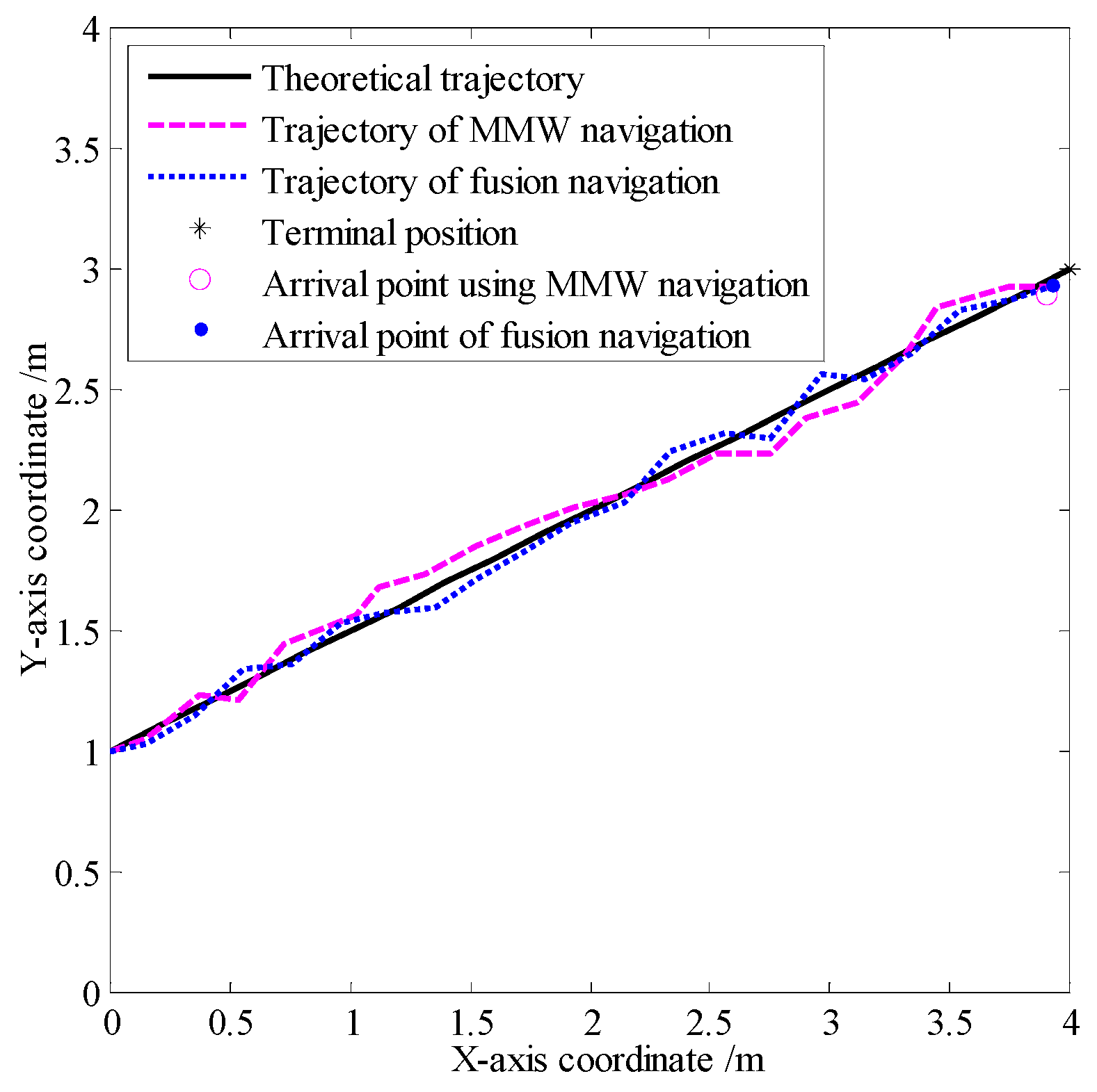
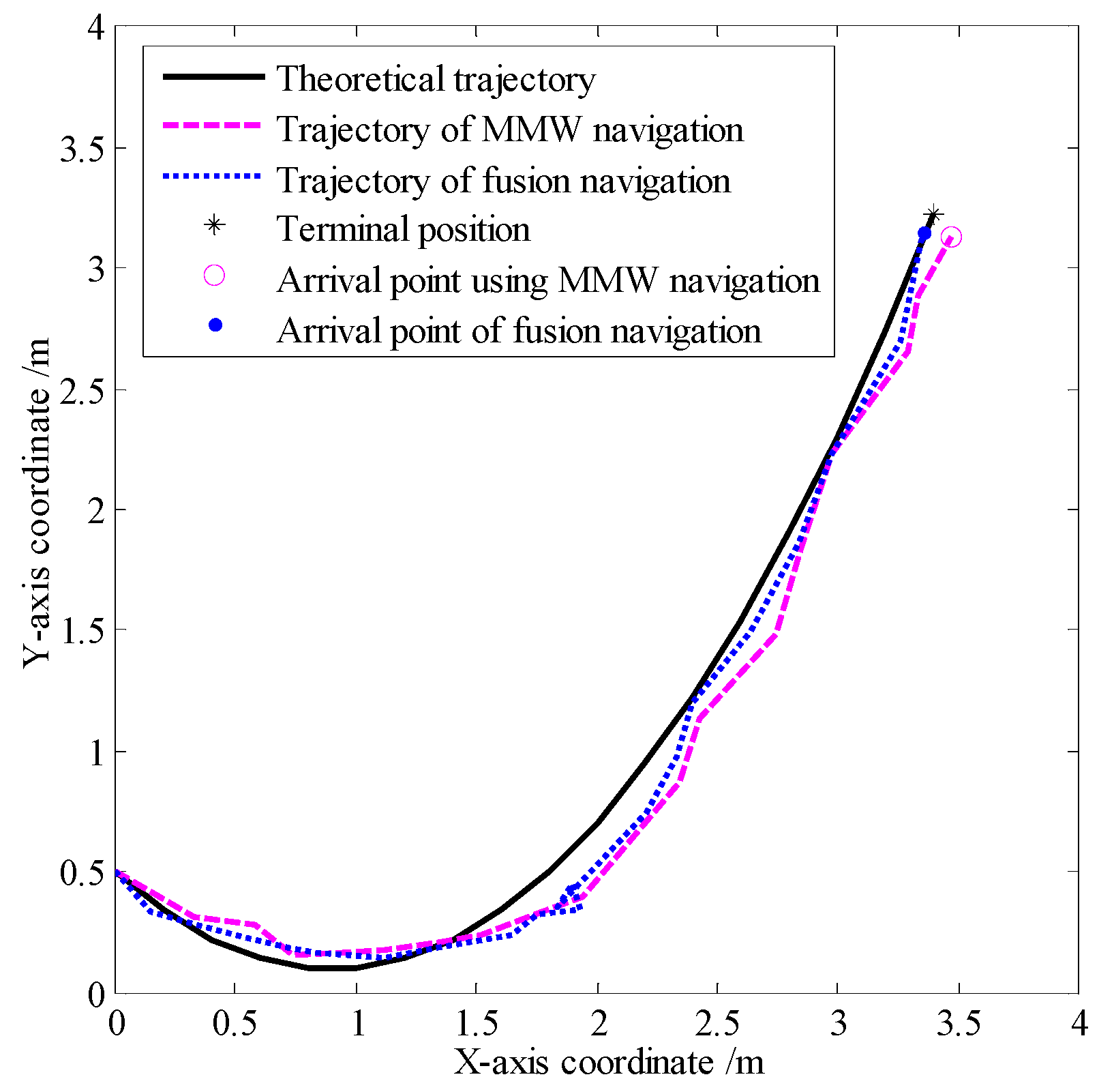
| Localization error | |
| Error of the MMW navigation system | 0.11 |
| Errors of the fusion navigation system | 0.083 |
| Localization error | |
| Error of the MMW navigation system | 0.11 |
| Errors of the fusion navigation system | 0.086 |
Disclaimer/Publisher’s Note: The statements, opinions and data contained in all publications are solely those of the individual author(s) and contributor(s) and not of MDPI and/or the editor(s). MDPI and/or the editor(s) disclaim responsibility for any injury to people or property resulting from any ideas, methods, instructions or products referred to in the content. |
© 2024 by the authors. Licensee MDPI, Basel, Switzerland. This article is an open access article distributed under the terms and conditions of the Creative Commons Attribution (CC BY) license (http://creativecommons.org/licenses/by/4.0/).


