1. Introduction
This work aimed to develop and control a soft inflatable actuator meant for a pneumatically actuated soft robotic grip for a robot arm, namely a Dobot robot [
1].
The performance of the soft robotic arm grip is dependent on the inflatable actuator therefore a set of design requirements were formulated to guide the design process: large range of motion, actuation under small amounts of pressure, and, finally, simple and fast manufacturing. So, the actuator must be highly compliant and manufactured with molds or additive fabrication methods [
2,
3,
4].
Digital prototyping changes the paradigm of soft actuators development. Soft actuators with a series of elastic actuators can be built with rigid materials [
5] or with variable stiffness [
6,
7,
8].
Although the mechanical design plays a fundamental part in soft inflatable actuators, the set of available design parameters is large: geometry, elastic material properties, actuated medium (air or water, for example), methods of fabrication (inducing specific required deformations or opposing design requirements), actuation modes, positive or negative pressure, and the list continues. Here, it is expected to rely on natural designs [
9,
10] for inspiration and to reduce the parameter value space.
Various geometries of linear bellow-type actuators are possible [
2,
4,
11] and analytical models describing the stiffness of the actuators of different geometries are given [
12]. Although the models presented in [
13] are still designs, their geometries can be extrapolated to soft material actuators [
14].
Extensive literature review seems to show that no all-size-fit-all design exists. This work restricts the design to an elastic inflatable actuator under positive pressure, namely, PneuNet soft actuators [
7]. PneuNet (pneumatic networks) consists of a series of channels and chambers inside an elastomer. These channels inflate when pressurized, expanding in the most compliant regions and, therefore, motion. The behavior of PneuNet actuators can be customized by modifying the geometry of their chambers and the materials' properties. PneuNet for soft robotic actuators combines high actuation rates with high actuator reliability [
2,
7,
12].
PneuNet actuators are characterized by their inherent softness and compliance, making them ideal for scenarios where rigid actuators are unsuitable. They are also lightweight, which benefits systems where weight is a critical factor. These two advantages were significant in deciding which approach to take for the Dobot gripper. Additionally, their softness ensures safer interactions, particularly in human-robot interfaces or for gripping touch-sensitive materials. However, designing PneuNet actuators to achieve specific behaviors requires meticulous planning, design and optimization, and time. The performance of a PneuNet actuator is also influenced by changes in pressure, tending to have slower response times compared to other types of actuators. Considering some of these advantages and disadvantages, this paper presents the development of PneuNet-type actuators for a Dobot robot gripper.
This paper is divided into the following sections:
Section 2 presents the materials and methods used in this work;
Section 3 presents the simulation and experimental results obtained and their discussion and
Section 4 presents the conclusions.
2. Materials and Methods
2.1. Modelling Bending Behavior of PneuNet Actuators
Modeling PneuNet actuators analytically remains complex due to their construction using entirely flexible, hyperelastic materials. Their inherent bending curvature and stiffness change with varying input pressure [
15]. This section aims to summarize the mathematical modeling that establishes the relationship between the curvature/ bending angle of the actuator and the input pressure. Later in this work, the simulation and experimental results for these two variables are presented for the actuators developed.
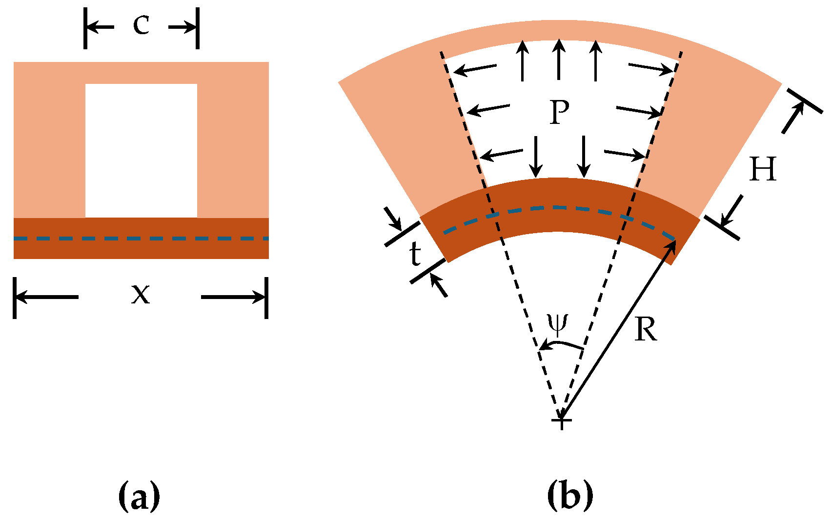
Majidi et al. [
16] established a mathematical correlation between the input pressure and the bending curvature of a PneuNet actuator with a fixed chamber height (
Figure 1 and Equation 1). This model, based on the principle of minimum potential energy, shows that the actuator's curvature kp is directly proportional to the input pressure (P) as follows:
The chamber geometry and the material's properties influence the constant (D). It is assumed that the modulus of elasticity (E) remains constant, simplifying the model for hyperelastic materials, and the impact of gravity is disregarded. Another significant contribution in this area is the bending angle model introduced by Alici et al. in their work [
17]. They formulated a method to predict the bending angle of a PneuNet actuator with a fixed chamber height based on input pressure, considering the actuator as a cantilever beam (equation 2).
By applying Euler–Bernoulli beam theory and assuming that the actuator bends into a uniform curvature, they derived the following steady-state relationship:
Constants (C) and (D) are influenced by the geometry of the chambers and the material properties, where
A and
Aw are the cross-sectional areas of the chamber,
I is the area moment of inertia,
e is the offset between the center of pressure and the neutral axis of the chamber. This model considers the chamber and gap between two chambers as a single unit with a length of
Li. In this context, the bending angle changes nonlinearly with input pressure, making it a potentially better model for PneuNet constructed with hyperelastic materials, as constant (C) is inversely related to the square of (E). Assuming a constant curvature, if a PneuNet actuator is anchored at one end and is free to bend at the other, the bending moment (M) generated by the pressure force and the internal area of the pneumatic chambers will move the actuator from its initial to its final position [
15].
2.2. Modeling of the actuators and gripper
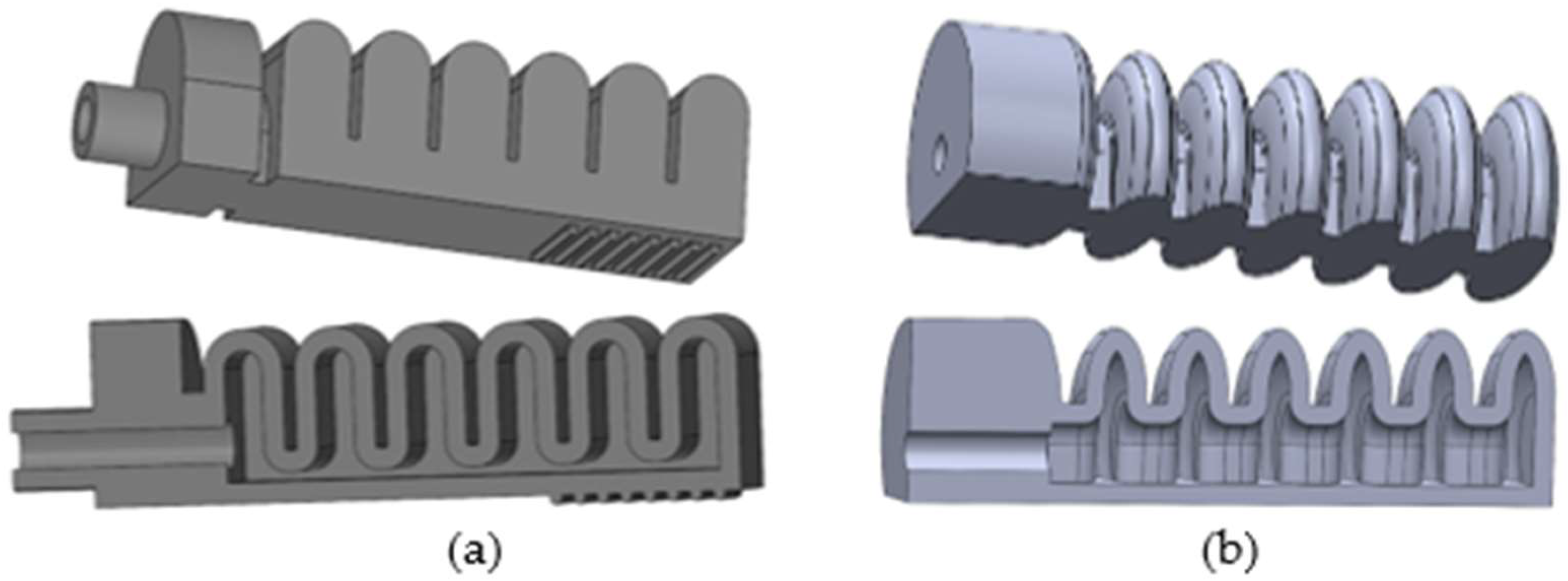
Two different models of PneuNet actuators have been 3D modeled in Solidworks Student
® and fabricated with fast prototyping methods: type 1 (
Figure 2(a)), inspired by Yap et al. [
18] and type 2 (
Figure 2(b)) that was inspired by Patel et al. [
19].
Two different production methods were used: (1) 3D printing by Fused Deposition Modelling (FDM), where Filaflex filament was used, and (2) Fabricated molds, where two distinct silicones were used: DragonSkin Fast 10 and Elastosil M4601 A/B. FilaFlex 60A was used because, among the several types of this filament, it had lower Shore hardness and higher elongation.
In
Figure 3, PneuNet actuators of type 1, fabricated with FDM printed molds, using the two silicones can be seen:
Figure 3(a) DragonSkin Fast 10 and
Figure 3(b) Elastosil M4601 A/B.
Table 1,
Table 2, and
Table 3 show the properties of the two silicones and Filaflex 60 filament used in this work:
Both mold halves can be seen in Figures 4(a) and (b). To obtain the interior cavity of the PneuNet actuator a third component, acting as a core mold part, had to be assembled beforehand (see
Figure 4(c) depicting both mold halves and the central core). The uncured silicone was put in both halves of the mold, one containing the rigid core, held in place due to its L shape at one end. The two mold halves were closed, centered by the six centering pins (
Figure 4), smashing the silicone against the core and mold walls up to the complete closing of the mold. The excess air and liquid silicone material could be extracted from the mold holes and parting line.
After the silicone curing, that plastic core could be extracted from the PneuNet actuator by pulling it with pointed pliers or other tool from the orifice where the air enters the actuator. The molds and inner core were made from Polylactic Acid (PLA). Different solutions were tested, e.g. having a core made of Polyvinyl Alcohol (PVA) to be dissolved with water, but this proved unsuccessful due to the water reacting with silicone.
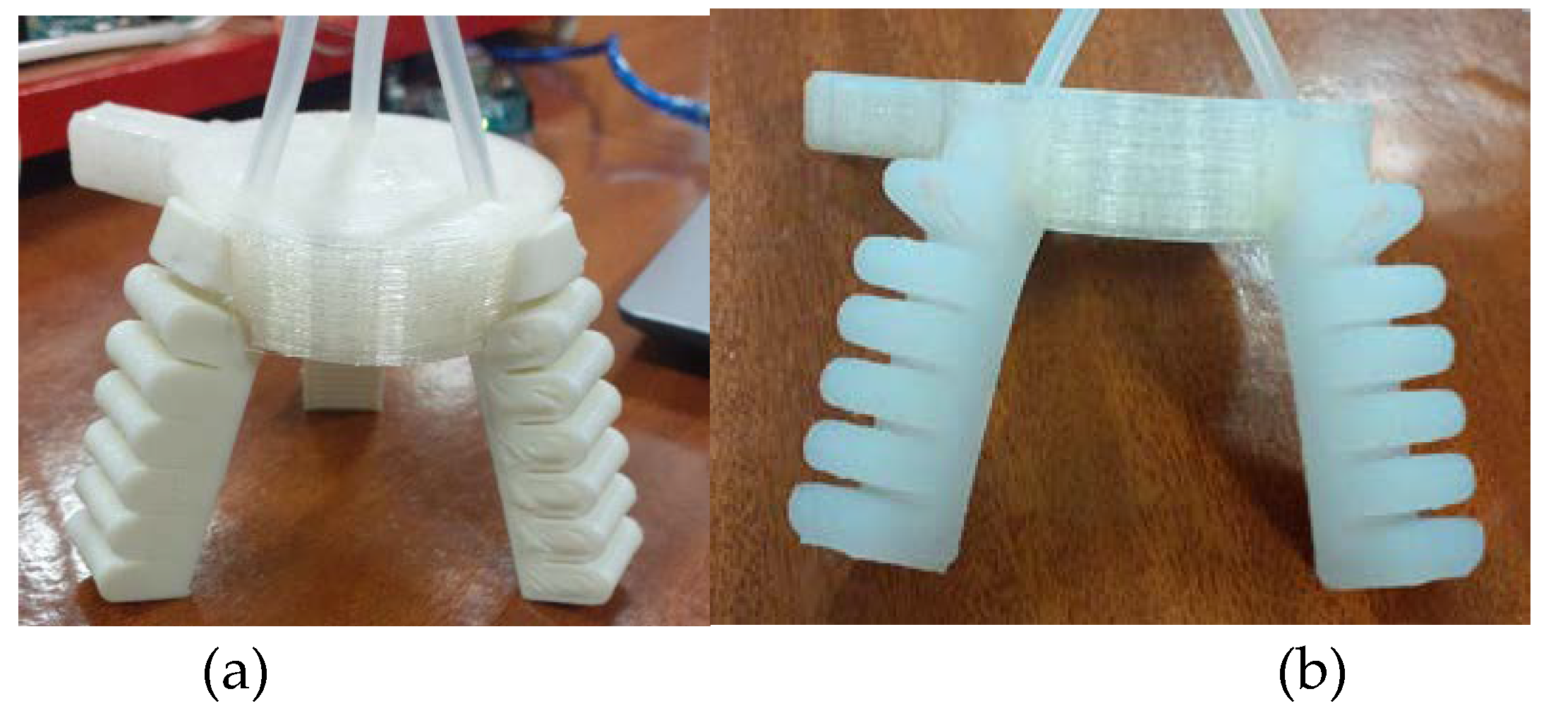
The type 1 PneuNet actuator was also fabricated with FDM 3D printing with Filaflex 60A filament (
Figure 5).
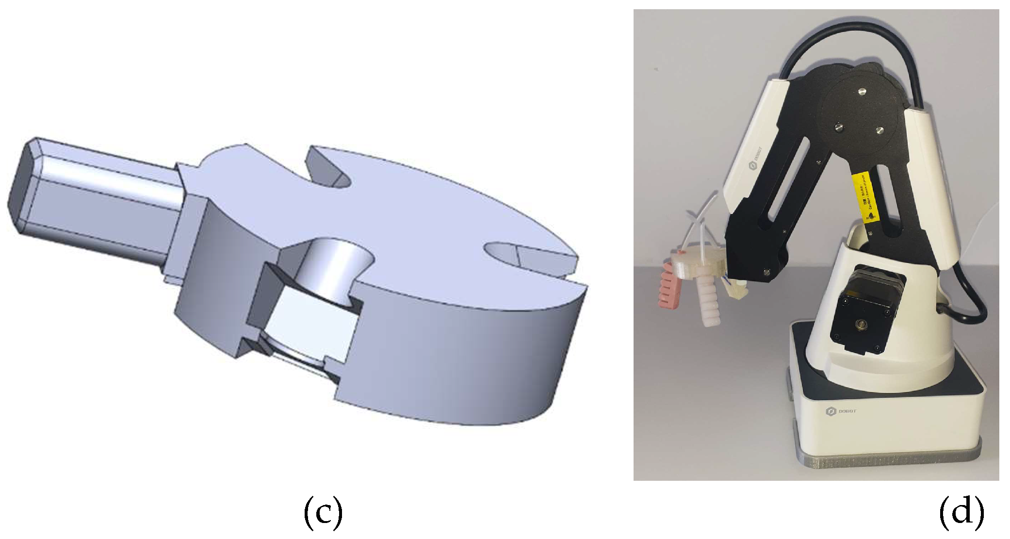
In
Figure 6, the PneuNet actuators, obtained by FDM (
Figure 6(a)) and molds (
Figure 6(b)), can be seen mounted in the Dobot gripper (it uses three actuators). The three actuators fit into the coupling base (
Figure 6(c)) of the gripper which was FDM printed with PLA material.
2.3. Control of the Soft Gripper
To demonstrate a use-case application of the proposed soft actuators, a robotic gripper with three soft actuators was integrated into the pick and place operations of a Dobot robot (
Figure 6(d)). This section describes the control system used to drive the gripper's grab/release cycles in the context of these tasks.
2.3.1. Pneumatic and electronic circuits
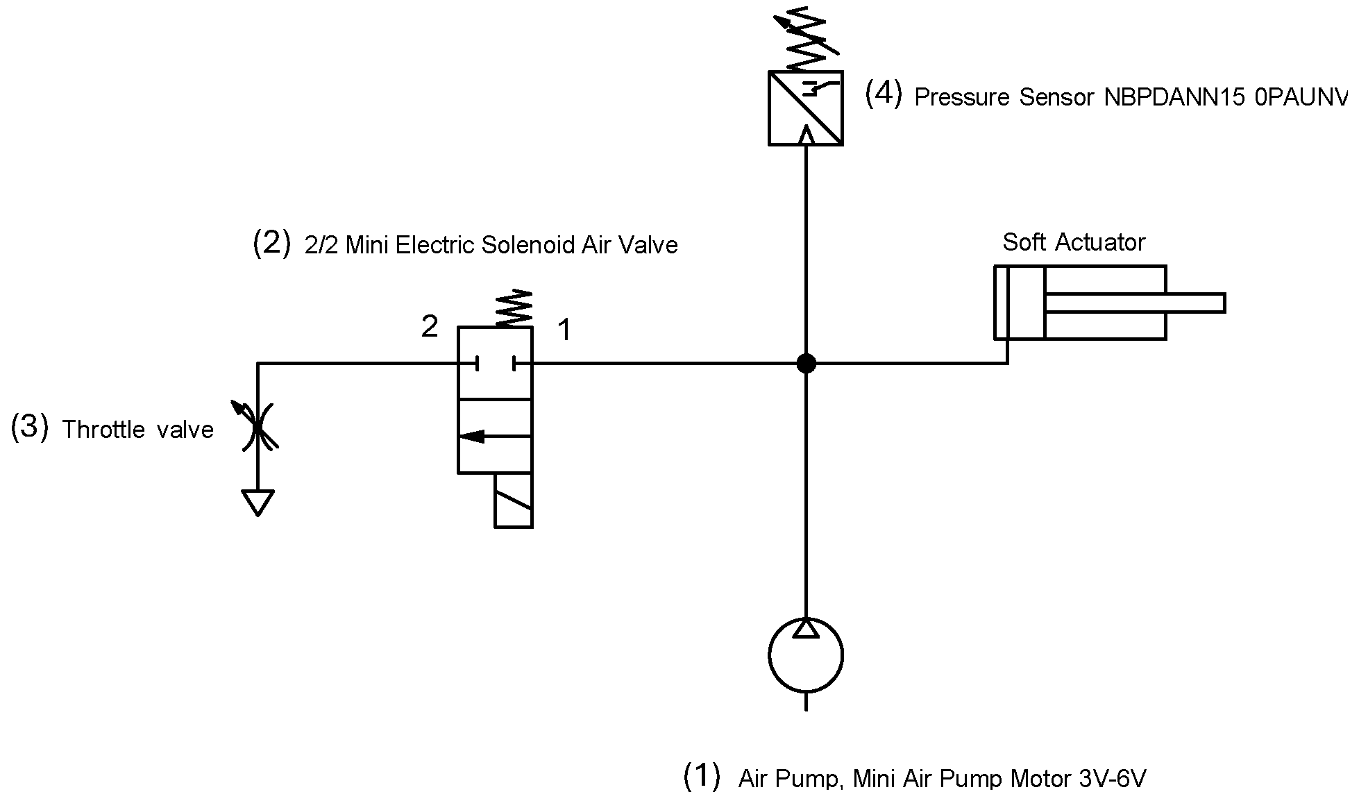
The pneumatic circuit that was devised to supply pressurized air into the soft actuators consists of (1) a mini diaphragm air pump, (2) a 2-way, 2 position solenoid valve, (3) a throttle valve and (4) a pressure sensor, connected as depicted in
Figure 7.
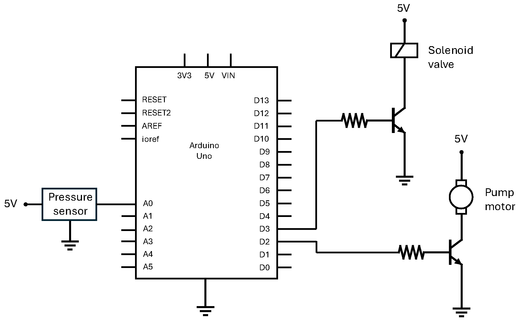
The control logic is run on an Arduino board, which receives the analog reading from the pressure sensor and outputs two control signals that regulate the current through the solenoid valve and the pump via two power transistors, as shown in
Figure 8. The goal of the control system is to drive simple grab/release cycles of the gripper thus, the pressure in the actuators should follow a waveform that goes from atmospheric pressure (release) to a reference pressure (grab) and back to atmospheric pressure (release). Here, pressure is the single controlled variable, and a desired curvature (kp) of the actuators is achieved by selecting the corresponding pressure, as given by the pressure-curvature relation described in section 2.1. An alternative to this approach would be to embed strain sensors into the soft actuator [
25,
26] and implement a control loop that directly targets curvature.
In the present work pressure is mainly controlled by modulating the speed of the pump. This is in strong contrast to the most common approach, which involves using a constant source of pressurized air combined with two on/off solenoid valves that regulate the flow in and out of the actuator [
26,
27,
28,
29]. In that approach pressure is controlled by switching the valves at a high frequency, thereby regulating the airflow into and out of the actuator. To achieve this, the valves are driven by PWM signals, which duty cycles take the role of the control action, i.e., they are continuously adjusted to achieve the desired pressure. Differently, in the currently proposed approach, the valve is commanded by a digital signal that occasionally changes state, whereas a PWM signal drives the pump.
It follows that a pressure increase is achieved by closing the valve and powering the pump through a suitable control law while pressure reduction is attained by turning off the pump and opening the valve. Now, while the PWM signal can continuously modulate the pressure rise, pressure reduces abruptly when the valve is opened. To avoid sudden falls of pressure due to the on-off nature of the valve, a throttle valve is connected to the valve exit. In this way, the pressure falls more slowly, resulting in a slightly slower opening of the gripper, which, on the other hand, reduces oscillations. But most important is the effect of the throttle valve when the transient response of the system is oscillatory. In this case, a fast decrease in pressure, associated with the inherent delays of the pneumatic system, gives rise to oscillations. This can be attenuated with the introduction of a throttle valve, which contributes to an amount of damping that can be adjusted to mitigate that behavior. The addition of damping through a pneumatic component was used previously in [
28,
29], where the authors resorted to a tube fitted with a porous plug which acts as a pneumatic low pass filter.
Past research on soft actuator control has led to sliding mode controllers [
30,
31,
32], model reference adaptive controllers [
33] and robust adaptive controllers [
26,
27], among others. The use of advanced controllers such as these is justified by the inherent challenges in soft actuator systems, in particular, the non-linearities due to the hyperelasticity of the material and the PneuNet geometry, the nonlinear behavior of pneumatic components and the delays in air distribution [
27]. Still, situations exist where simpler controllers, such as PIDs, can be used, with the benefit of a more straightforward implementation and ease of reconfiguration, possibly at the cost of lower performance. In this regard, when selecting a controller for soft actuators, it should be remembered that an intrinsic advantage of these actuators is their compliance, increasing tolerance to errors. Given the simplicity of the task of opening/closing the soft gripper, and the acceptable tolerance to actuator position errors, two simple strategies, proportional-integral (PI) and On-Off, are considered in this work. The resulting control systems are nonlinear since, as mentioned before, different rules concerning the pump and valve are defined for positive (pressure rise) and negative (pressure reduction) control actions. Also, the valve behavior is non-linear by nature. In the first control strategy, henceforth denoted as nonlinear PI, the pump's duty cycle is determined from the pressure error and accumulation of error. The second is an On-Off controller, where both the valve and the pump have binary states.
2.3.2. Nonlinear PI control
The PI control action is computed by combining a term proportional to the error and a second term proportional to the integral of the error [
34]. This is used to calculate the duty cycle of the pump. However, when the control action is negative, the pump must be stopped, and the valve actuated instead. This mechanism can be implemented through algorithm 1.
|
Algorithm 1 Non-linear PI Controller |
| 1: |
integral = 0 |
| 2: |
repeat: |
| 3: |
error = reference − pressure |
| 4: |
integral = integral + error × dt |
| 5: |
uPI = Kp × error + Ki × integral |
| 6: |
if uPI ≥ 0 then
|
| 7: |
upump = uPI
|
| 8: |
uvalve = closed |
| 9: |
else |
| 10: |
uvalve = open |
| 11: |
upump = 0 |
In the above algorithm the following symbols are used:
reference – desired pressure
pressure – actual pressure
dt – sample time
uPI – proportional-integral control action
Kp – proportional gain
Ki – integral gain
upump – duty cycle of the pump
uvalve – valve state
2.3.3. On-Off controller
In a typical On-Off controller, there is an actuator with two possible states, On and Off [
34], and state changes occur when the control error exceeds a specific interval set around zero. This typically leads to oscillating behavior with switching times that depend on the gap between the interval limits.
In this case, there are two actuators, the pump and the valve, and an On-Off rule can be set for each, which offers more flexibility in designing the controller behavior. Essentially, the pump should be switched On when the error is positive and exceeds the positive threshold. The valve should be opened when the error is negative and falls below the negative threshold. In addition, each actuator should be switched Off when the error crosses zero. Accordingly, the proposed on-off controller can be described by algorithm 2:
|
Algorithm 2 On-Off Controller |
| 1: |
upump =0 |
| 2: |
uvalve = closed |
| 3: |
repeat: |
| 4: |
if e > threshold then
|
| 5: |
upump = PWMON
|
| 6: |
if upump > 0 and e < 0 then
|
| 7: |
upump = 0 |
| 8: |
if e < −threshold then |
| 9: |
uvalve = open |
| 10: |
if uvalve = open and e > 0 then |
| 11: |
uvalve = closed |
Where PWMOn is a constant duty cycle selected for the On state of the pump and threshold is the maximum allowed error above which a control action is triggered.
3. Simulation and experimental results
3.1. Introduction to simulation results
This section explains the numerical simulation of the PneuNet actuators, fabricated with the three different materials (two silicones with molds and Filaflex by FDM), and compares it with the experimental behavior for several input pressure values. The numerical simulation was made using the Finite Element Method (FEM) with the student version of software ANSYS Workbench®.
The Finite Element used was a 10-node quadratic tetrahedral solid element. The actuators were fixed at the supporting area, and pressure was applied at the inner walls. Self-contact and gravity acceleration were also included in the analysis. Only static studies were made.
Since elastomeric rubbers do not behave linear elastically over deformation and have an enormous elastic extension, they should be modeled as hyperelastic material in FEM software. The hyperelastic material models used were the second-order Mooney-Rivlin and the third-order Yeoh.
As Yap et al. [
18] noted, the 3D printed elastomer can have an anisotropic behavior. In the present work it was assumed that its behavior was isotropic.
Hyperelastic material models
Both silicones were studied successfully by other authors using the 3
rd order Yeoh hyperelastic model: [
35] studied DragonSkin Fast 10, and [
36] studied Elastosil M4601 A/B.
The 3
rd order (N=3) Yeoh model strain energy potential is given by eq. 1 [
37]:
where, is the first deviatoric strain invariant;
J is the determinant of the elastic deformation gradient;
N, and are material constants.
For the FDM 3D printed material, FilaFlex 60A, the 3
rd order Mooney-Rivlin model was applied, as also done by [
38].
The 2
nd order (N=2) Mooney-Rivlin model strain energy potential is given by eq. 2 [
37]:
where,
and
are the first and second deviatoric strain invariants, respectively.
,
are material constants, characterizing the deviatoric deformation of the material. d is the material incompressibility parameter.
Table 4 presents the hyperelastic material properties used in the models:
3.1. FEM and Experimental Results Comparison
In this section FEM and experimental results are shown and analyzed. FEM results of the two actuator types and three materials are shown for several input pressures. Then, measured angles, both in FEM and experimental, for one extreme situation are compared.
3.3.1 Type 1 Silicone actuators results
The PneuNet actuator of type 1 is shown in
Figure 9 in a deformed shape.The model mesh was generated with 21591 elements and 36565 nodes. In this figure only the effect of gravity is observed, as no internal pressure input was applied to the model at this stage.
As explained, simulations were carried out on both silicones’ actuator types using the Yeoh hyperelastic model. Given the contrasting properties of the two silicones, different pressure ranges were simulated for each. Specifically, for the DragonSkin Fast 10 a pressure range from 0 kPa to 40 kPa (0.4 bar) was used;and for Elastosil M4601 A/B the pressure ranged from 0 kPa to 100 kPa (1 bar).
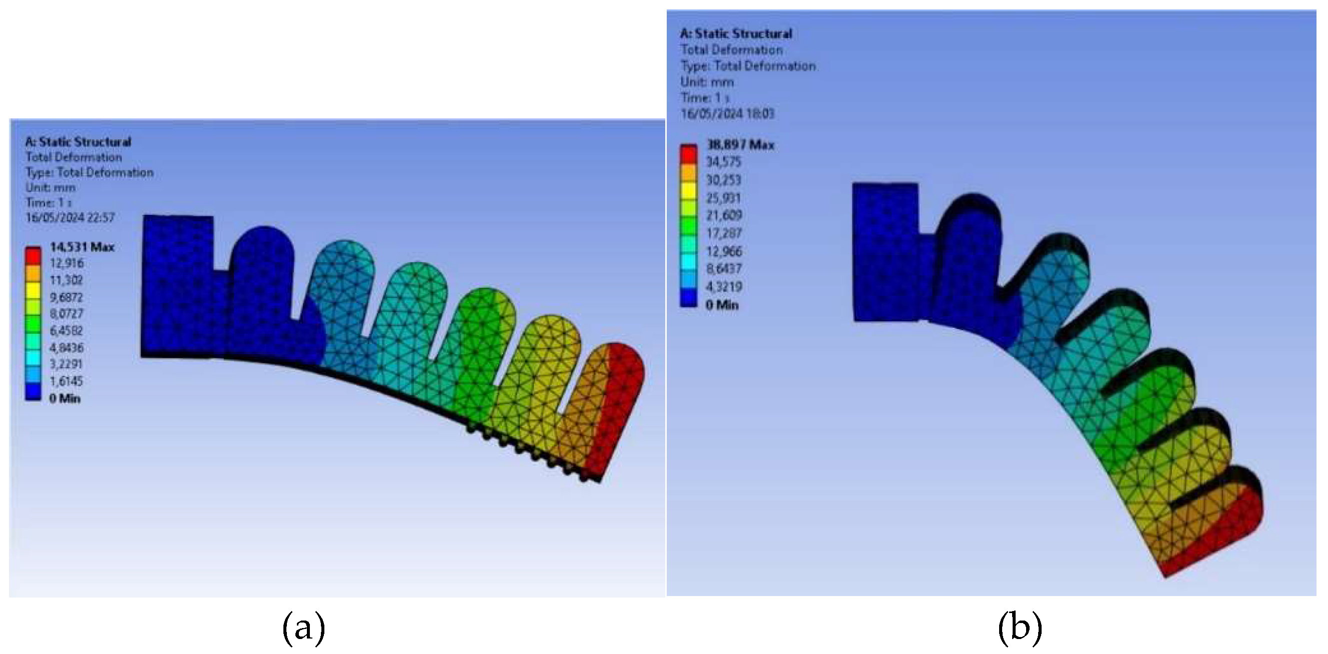
In
Figure 10, both FEM models can be seen for the pressure of 40 kPa (0.4 bar).
In
Figure 11, a comparison is made for Elastosil M4601 A/B silicone between the FEM model (
Figure 11(a)) and the real actuator (
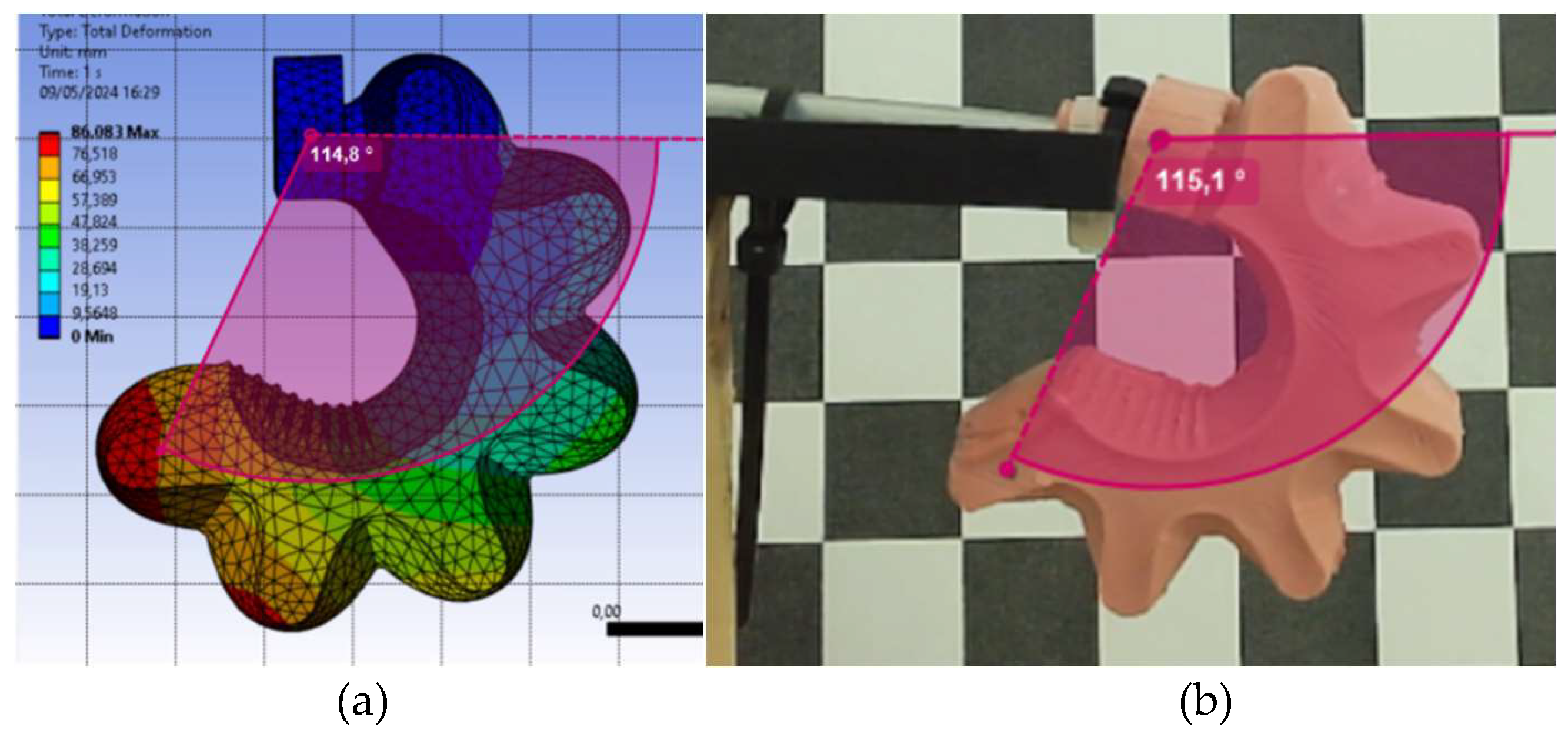
Figure 11(b)), both subjected to the maximum pressure of 100 kPa (1 bar). The experimental model rotation angle was measured with Kinovea software and has the value of 115.1°. The FEM model angle was 114.8°, with gives a very good approximation.
In
Figure 12, the same type of comparison as
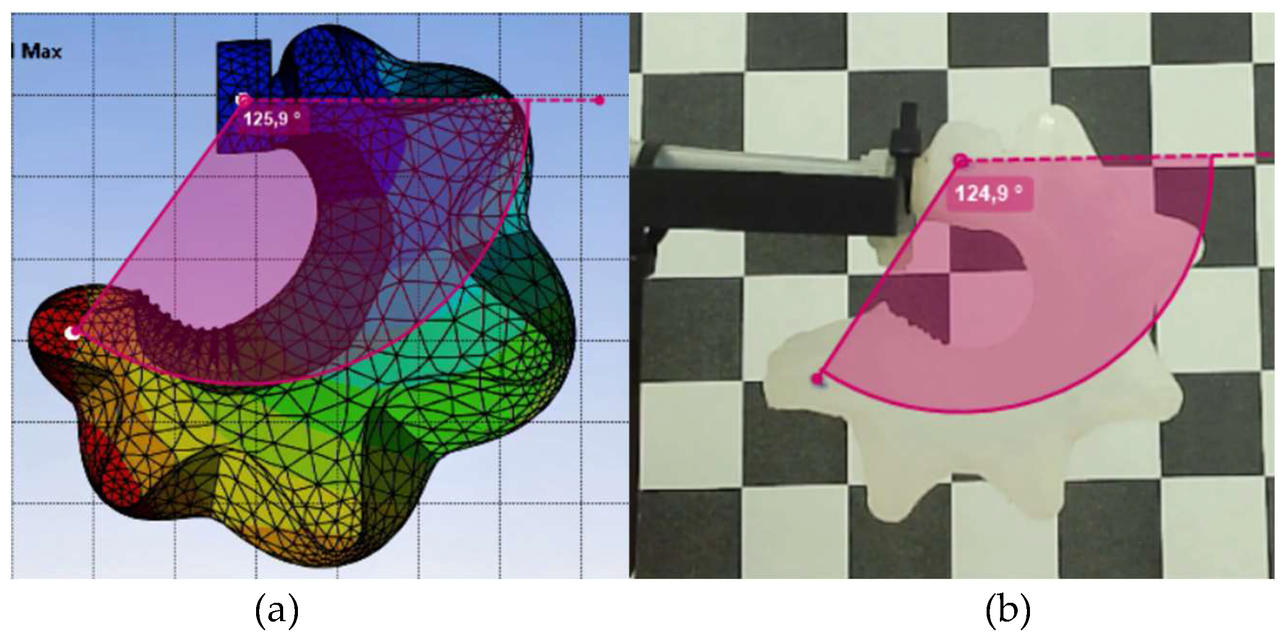
Figure 11 is made, but in this case for the Dragon Skin Fast 10 material with the maximum pressure of 40 kPa (0.4 bar). The experimental model measured rotation angle has the value of 124.9° The FEM model obtained angle was 125.9°, having 1 degree of difference which gives an excellent approximation.
Figure 13 and
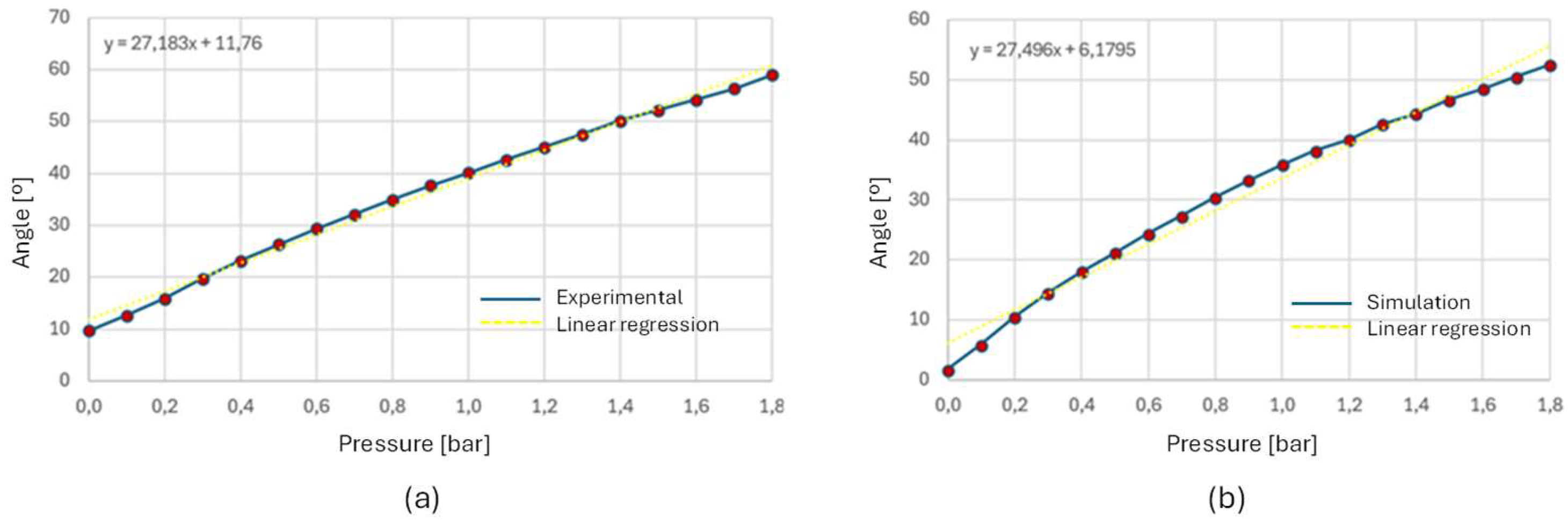
Figure 14 show the angular behavior curves (bending angle vs pressure), obtained experimentally and by FEM simulation of the type 1 actuators and with the two types of silicones used. The simulation and experimental bending angle consistently follow the non-linear models used in the simulation and prove the non-linear bending angle model of equation 2. The experimentally built actuators had a more linear behavior, probably due to construction details and real material behavior. To bring the two curves closer together, the parameters of the models should be adjusted to the reality obtained experimentally.
3.3.2 Type 1 and 2 actuators results with FDM Filaflex60A
This subsection addresses the simulation and experimental results of the actuators made with FDM Filaflex60A.
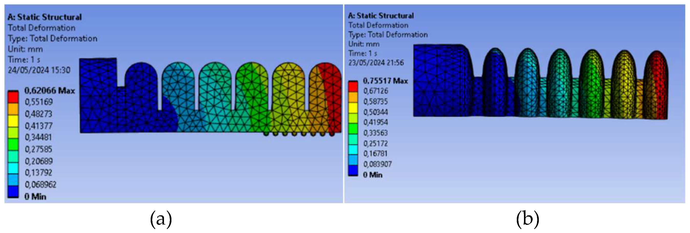
Figure 15(a) shows the type 1 model in a deformed shape due to gravity and no pressure being applied. The model mesh was generated with 21591 elements and 36565 nodes.
Figure 15(b) shows the type 2 model, which has 23702 elements and 39896 nodes, under the same conditions.
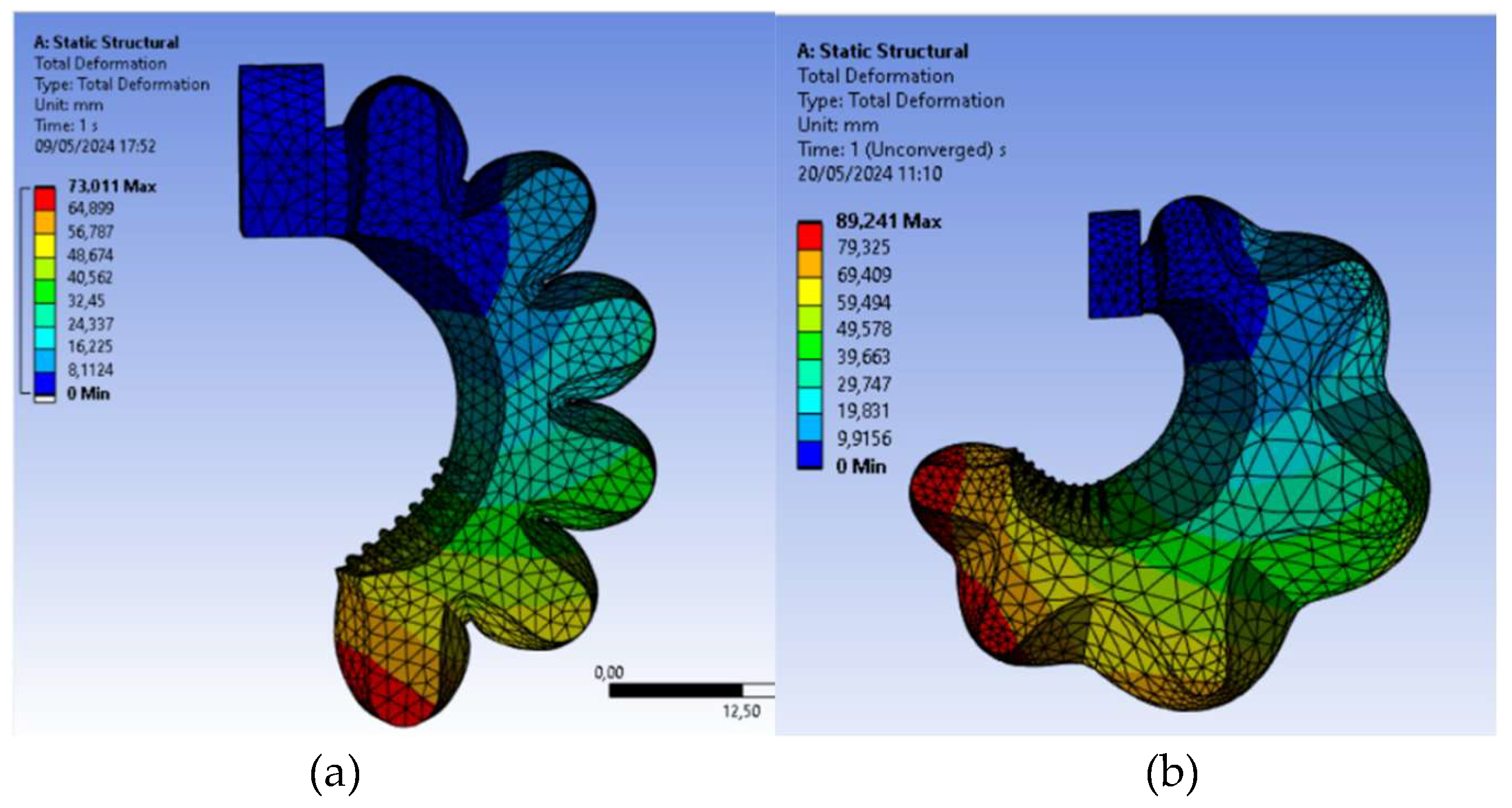
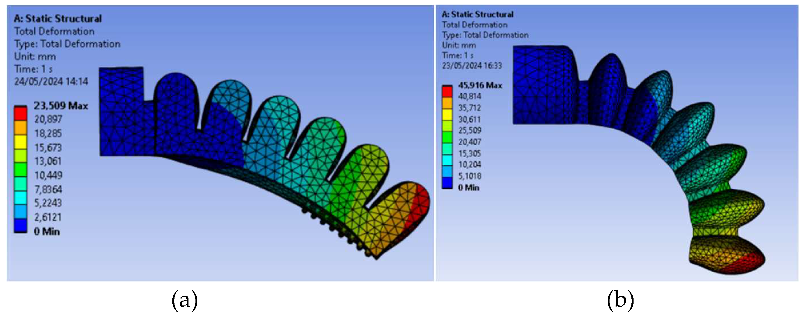
In
Figure 16, both FEM models can be seen for the pressure of 180 kPa (1.8 bar). It can be seen that the type 2 actuator produces a larger bending angle for the same pressure.
In
Figure 17, a comparison is made for the type 1 actuator, between the FEM model (
Figure 17(a)) and the real actuator (
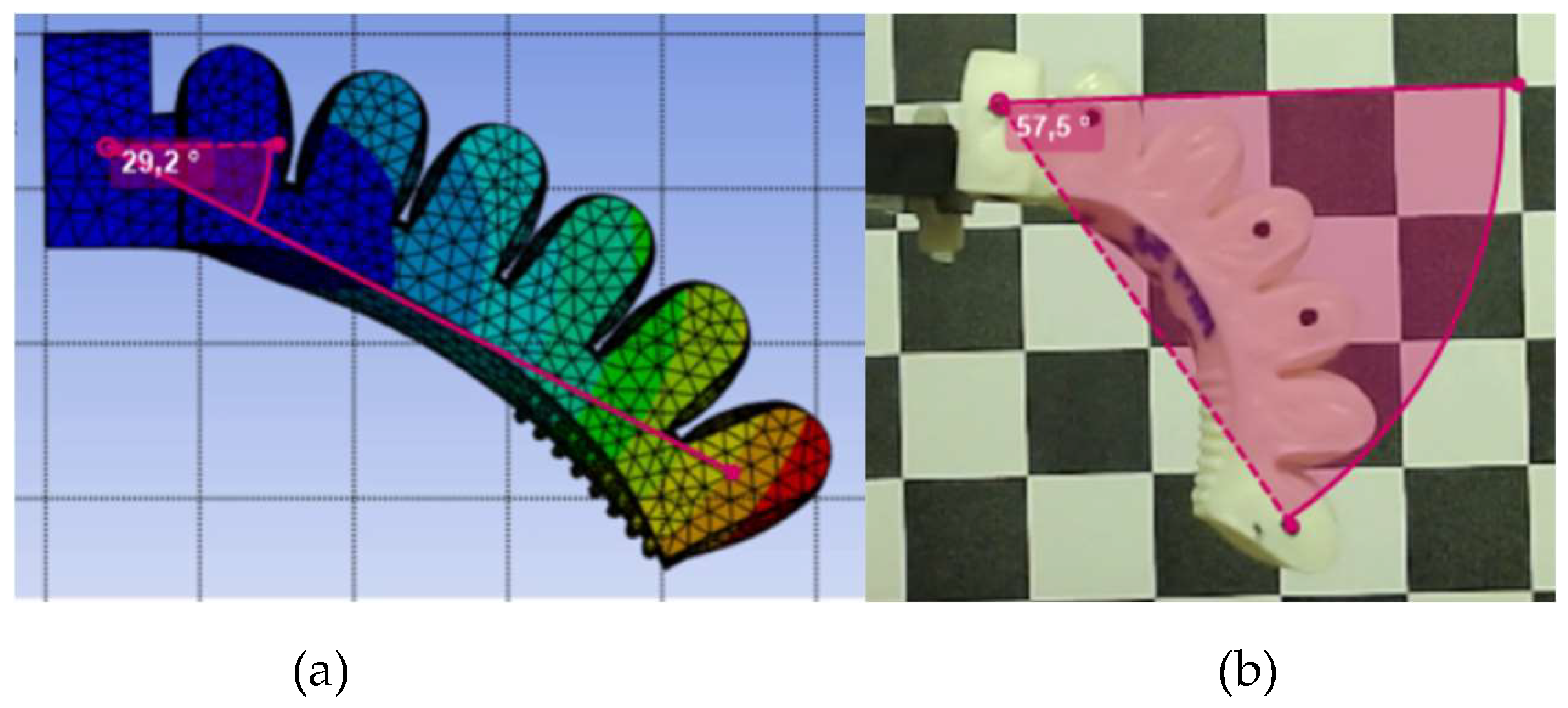
Figure 17(b)), both subjected to the maximum pressure of 250 kPa (2.5 bar). The experimental model rotation angle was measured with Kinovea software and has the value of 57.5°. The FEM model angle was 29.2°, which gives a very bad approximation of the experimental value. The FEM model properties, among others, must be investigated.
In
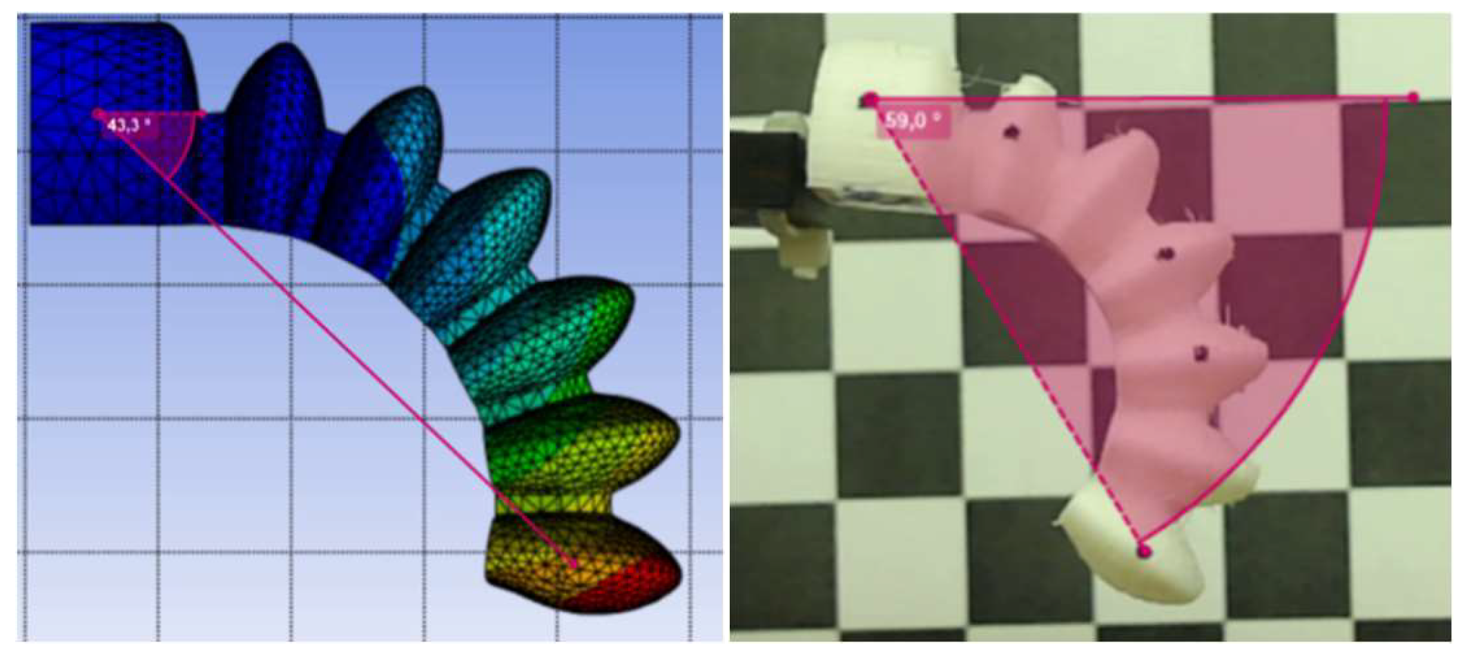
Figure 18, the same comparison is made for type 2 actuator. The experimental model rotation angle was measured as 59°. The FEM model angle was 43.3°, which gives a better approximation of the experimental result than the one obtained for type 1, with Filaflex 60A.
Figure 19 and
Figure 20 show the angular behavior curves (bending angle vs pressure), obtained experimentally and by FEM simulation of the type 1 and 2 actuators and with the Filaflex 60A filament. The simulation and experimental bending angle also consistently follow the non-linear models used in simulation and support the non-linear bending angle model of equation 2. The 3D printed actuators had a more linear behavior, probably due to 3D printing construction details and intrinsic material behavior. To bring the two curves closer together, the parameters of the models should be adjusted to the reality obtained experimentally.
It can be concluded that the use of FEM simulations is a very important tool to predict the natural behavior of the PneuNet actuators, enabling the designing and virtual testing of multiple configurations and the optimization of parameters such as lengths, thicknesses, materials, pressures, etc. to attain the best solutions.
3.2. Control results
This section presents results of pressure control experiments that were carried out to validate the proposed controllers. The gripper with soft actuators made of DragonSkin Fast 10® silicon was chosen for these experiments. Besides the results presented here, a series of experiments were performed to empirically adjust several control parameters to improve performance, namely Kp, Ki, PWMON, threshold and the throttle valve opening ratio. Although the influence of some of these parameters is interdependent (e.g. Kp and Ki), it has proved easy to find acceptable values for them through trial and error. This procedure led to the following constants, which were used in the experiments reported below.
Kp = 5000 bar-1
Ki = 2000 bar-1s-1
dt = 10 ms
threshold = 0.01 bar
throttle valve opening ration = 5%
Additionally, readings from the pressure sensor (model NBPDANN150PAUNV [
39]) were filtered through a low pass filter with a cutoff frequency of 6.8 Hz.
All experiments consist of system step responses, with the desired pressure being varied from 0 to a positive pressure and back to zero. This waveform of the desired pressure results in consecutively closing and opening the gripper. To test closing the gripper with different soft actuator angles, step responses were obtained for goal pressures in the set {0.1, 0.15, 0.2, 0.25} bar.
Nonlinear PI controller
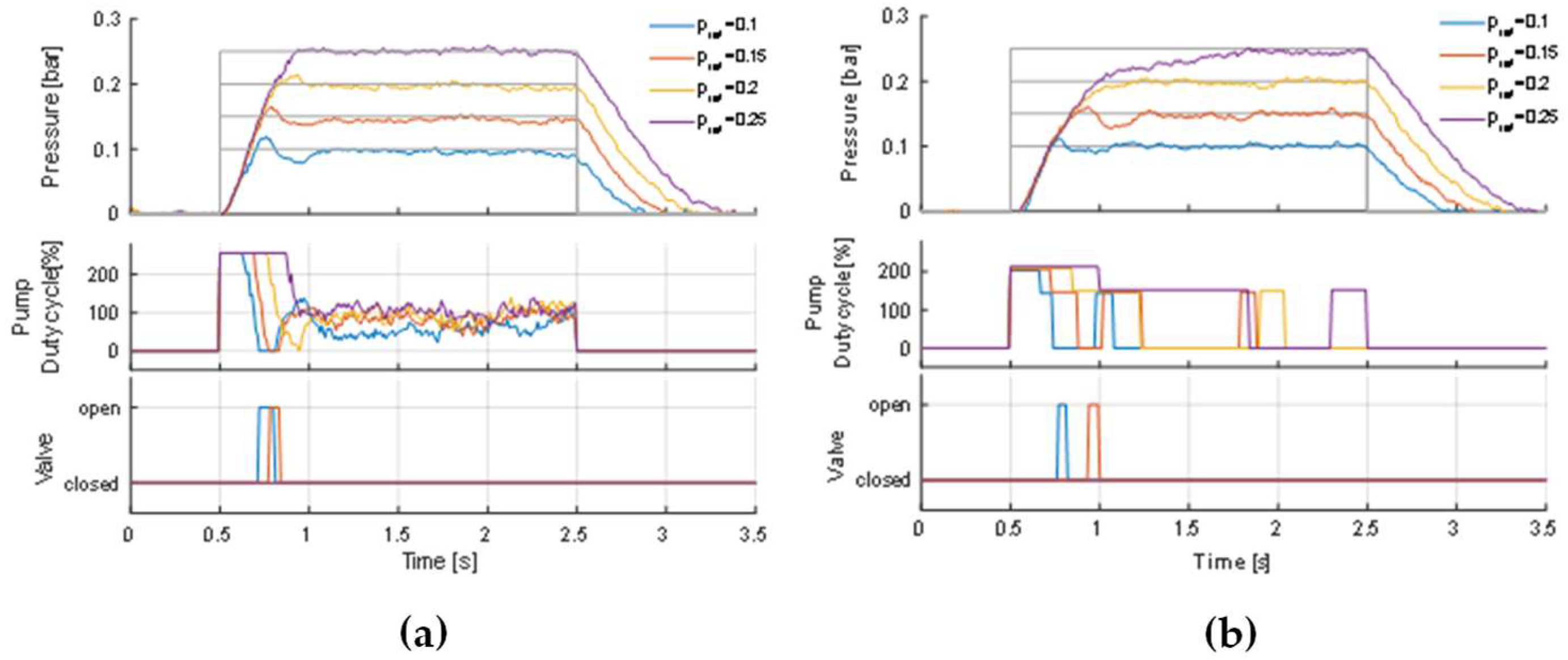
Figure 21. a shows the results obtained with the nonlinear PI controller, depicting the pressure and the control actions for the different input levels. The figure makes it clear that there are qualitative differences in the responses with the variation of the input level, which is a manifestation of the nonlinearities of the system and demonstrates the need to consider the range of the desired pressure when designing the controller. Most notably, the oscillatory behavior becomes less pronounced as the reference pressure increases and disappears entirely at 0.25 bar.
In two underdamped cases, the overshoot causes the controller to open the valve, which results in a pressure drop that is later compensated by the pump action. The throttle valve opening ratio has been adjusted so that this pressure drop is smooth enough not to cause further oscillations. This results in a longer time for the gripped opening, represented in the figure by the responses to the falling step in the reference. The higher reference pressure (0.25 bar), the transition to the ambient pressure takes about 0.8 s.
On-Off controller
The results obtained with the On-Off controller (
Figure 21.b) show some similarities with those of the PI controller regarding oscillatory behavior. Note that it was used two values of the duty cycle for the On state of the pump: a higher value, 80%, if the error is larger than 5×Threshold, and a lower value, 60%, for lower errors. In this way, it was possible to obtain a fast response at the beginning of the step input, due to the higher duty cycle, and at the same time avoid large overshoots, by using a lower duty cycle at lower error values. A comparison of the control actions of the two controllers reveals an advantage of the On-Off controller: in most cases, this controller results in the pump being switched Off for a large part of the gripper closing action. With the PI controller, on the other hand, the control action assumes significant values for the entire duration of the same period. This is due to the accumulation of errors and the fact that the pump motor stalls at higher pressures and, therefore does not contribute to eliminating the error. This not only leads to a waste of energy, but also to a deterioration in the performance of the motor.
4. Conclusions
This study presents the design, control, and testing of a multifunctional soft robotic gripper for a Dobot robot, based on pneumatic network (PneuNet) bending actuators. Two different models of PneuNet actuators were successfully developed using three materials: FilaFlex (3D printed), Elastosil M4601, and Dragonskin Fast 10 silicones (molded). The research demonstrates the viability of both 3D printing and molding techniques for fabricating soft robotic actuators, with each method offering unique advantages in terms of material properties and manufacturing processes.
Finite Element Method (FEM) simulations proved to be a valuable tool in predicting the behavior of PneuNet actuators. The simulations, using hyperelastic material models (Yeoh for silicones and Mooney-Rivlin for FilaFlex), showed good correlation with experimental results for the silicone-based actuators. However, significant discrepancies were observed in the FDM-printed FilaFlex actuators, where the predicted bending angle was consistently much lower than the experimentally measured angle. This suggests that the hyperelastic FEM models using the 2nd order Mooney-Rivlin model may be overly stiff for these 3D-printed materials, highlighting the need for further refinement of simulation parameters to accurately represent the behavior of 3D-printed soft actuators.
A key finding of this study is that the type 2 actuator, inspired by Patel et al. [
19], demonstrates a greater bending angle than the type 1 actuator, inspired by Yap et al., for the same applied pressure. This result has important implications for design optimization in soft robotic applications. Additionally, it was observed that FDM Elastosil actuators require significantly higher pressures to achieve the necessary curvatures for object grasping. While this higher-pressure requirement increases the operational costs due to compressor usage and elevates the risk of sudden rupture, the FDM printing method offers unparalleled freedom and speed in prototyping and producing new designs. This trade-off between performance, cost, and manufacturing flexibility presents an important consideration for future soft robotic gripper designs.
The results of this study lead to a crucial conclusion regarding material properties: actuators with a greater elastic component (lower Young's Modulus) yield more flexible results, achieving a greater range of movement with lower input pressures. This finding underscores the importance of material selection in soft robotic design, particularly when the goal is to maximize flexibility and minimize operational pressures. It suggests that softer, more elastic materials may be preferable for applications requiring large deformations at low pressures, while stiffer materials might be better suited for applications requiring higher force output or precision.
The implementation of both nonlinear PI and On-Off controllers for the pneumatic system demonstrated effective pressure control in the soft actuators. The controllers were able to manage the inherent nonlinearities and delays in the pneumatic system, with the On-Off controller showing potential energy efficiency advantages. The addition of a throttle valve proved crucial in mitigating oscillatory behavior, especially at lower pressures. These control strategies offer a balance between performance and simplicity, making them suitable for practical applications of soft robotic grippers.
Future work should focus on refining the FEM models, particularly for 3D-printed materials, to better predict their behavior under various operating conditions. Exploration of advanced control algorithms to further improve performance and energy efficiency is also warranted. Additionally, investigating the long-term durability of the soft actuators under repeated use, especially for the higher-pressure FDM actuators, will be crucial for practical applications. The integration of embedded sensors for closed-loop control and the exploration of more complex gripper designs could enhance the versatility and precision of the soft robotic system. Further research into the relationship between material properties, particularly elasticity, and actuator performance could lead to the development of new materials specifically tailored for soft robotic applications. This research contributes to the growing field of soft robotics, offering insights into the design, fabrication, and control of compliant grippers for sensitive object manipulation, while highlighting the complex trade-offs between manufacturing methods, material properties, and actuator performance.
Author Contributions
Conceptualization, A.C., T.C., F.C. and M.M.; methodology, A.C., T.C., F.C. and M.M.; software, A.C., A.L. and F.C.; validation, A.C., T.C., A.L., F.C. and M.M.; investigation, A.C, T.C., F.C., A.R. and M.M; resources, T.C., F.C., N.M., A.R. and M.M.; writing—original draft preparation, A.C., T.C., A.L., F.C., M.M.; writing—review and editing, F.C., N.M., A.R. and M.M.; supervision, T.C. and M.M.; project administration, M.M.; funding acquisition, M.M. All authors have read and agreed to the published version of the manuscript.
Funding
This research was funded within the IPL/IDI&CA2023/ACTSOFTLY_ISEL project.
Data Availability Statement
The original contributions presented in this study are included in the article/supplementary material, further inquiries can be directed to the corresponding author.
Conflicts of Interest
The authors declare no conflicts of interest.
References
- Robotics, D. Magician Robot - Desktop Grade Robot For Advanced Education Available online: https://www.dobot-robots.com/products/education/magician.html (accessed on 28 September 2024).
- Rus, D.; Tolley, M.T. Design, Fabrication and Control of Soft Robots. Nature 2015, 521, 467–475. [CrossRef]
- Tawk, C.; Alici, G. A Review of 3D-Printable Soft Pneumatic Actuators and Sensors: Research Challenges and Opportunities. Advanced Intelligent Systems 2021, 3. [CrossRef]
- El-Atab, N.; Mishra, R.B.; Al-Modaf, F.; Joharji, L.; Alsharif, A.A.; Alamoudi, H.; Diaz, M.; Qaiser, N.; Hussain, M.M. Soft Actuators for Soft Robotic Applications: A Review. Advanced Intelligent Systems 2020, 2. [CrossRef]
- Pratt, G.A.; Williamson, M.M. Series Elastic Actuators. IEEE International Conference on Intelligent Robots and Systems 1995, 1, 399–406. [CrossRef]
- Ham, R.; Sugar, T.; Vanderborght, B.; Hollander, K.; Lefeber, D. Compliant Actuator Designs. IEEE Robotics & Automation Magazine 2009, 16, 81–94. [CrossRef]
- Mosadegh, B.; Polygerinos, P.; Keplinger, C.; Wennstedt, S.; Shepherd, R.F.; Gupta, U.; Shim, J.; Bertoldi, K.; Walsh, C.J.; Whitesides, G.M. Pneumatic Networks for Soft Robotics That Actuate Rapidly. Advanced Functional Materials 2014, 24, 2163–2170. [CrossRef]
- Ang, B.W.K.; Yeow, C.H. 3D Printed Soft Pneumatic Actuators with Intent Sensing for Hand Rehabilitative Exoskeletons. Proceedings - IEEE International Conference on Robotics and Automation 2019, 2019-May, 841–846. [CrossRef]
- Kim, S.; Laschi, C.; Trimmer, B. Soft Robotics: A Bioinspired Evolution in Robotics. Trends in Biotechnology 2013, 31, 287–294. [CrossRef]
- Shepherd, R.F.; Ilievski, F.; Choi, W.; Morin, S.A.; Stokes, A.A.; Mazzeo, A.D.; Chen, X.; Wang, M.; Whitesides, G.M. Multigait Soft Robot. Proceedings of the National Academy of Sciences of the United States of America 2011, 108, 20400–20403. [CrossRef]
- Ogura, K.; Wakimoto, S.; Suzumori, K.; Nishioka, Y. Micro Pneumatic Curling Actuator - Nematode Actuator -. 2008 IEEE International Conference on Robotics and Biomimetics, ROBIO 2008 2008, 2008-Janua, 462–467. [CrossRef]
- Gu, G.; Wang, D.; Ge, L.; Zhu, X. Analytical Modeling and Design of Generalized Pneu-Net Soft Actuators with Three-Dimensional Deformations. Soft Robotics 2021, 8, 462–477. [CrossRef]
- Wilson, J.F. Mechanics of Bellows: A Critical Survey. International Journal of Mechanical Sciences 1984, 26, 593–605. [CrossRef]
- Sudani, M.; Deng, M.; Wakimoto, S. Modelling and Operator-Based Nonlinear Control for a Miniature Pneumatic Bending Rubber Actuator Considering Bellows. Actuators 2018, 7, 1–13. [CrossRef]
- Rad, C.; Hancu, O.; Lapusan, C. Data-Driven Kinematic Model of PneuNets Bending Actuators for Soft Grasping Tasks. Actuators 2022, 11. [CrossRef]
- Majidi, C.; Shepherd, R.F.; Kramer, R.K.; Whitesides, G.M.; Wood, R.J. Influence of Surface Traction on Soft Robot Undulation. International Journal of Robotics Research 2013, 32, 1577–1584. [CrossRef]
- Alici, G.; Canty, T.; Mutlu, R.; Hu, W.; Sencadas, V. Modeling and Experimental Evaluation of Bending Behavior of Soft Pneumatic Actuators Made of Discrete Actuation Chambers. Soft Robotics 2018, 5, 24–35. [CrossRef]
- Yap, H.K.; Ng, H.Y.; Yeow, C.-H. High-Force Soft Printable Pneumatics for Soft Robotic Applications. Soft Robotics 2016, 3, 144–158. [CrossRef]
- Patel, D.K.; Sakhaei, A.H.; Layani, M.; Zhang, B.; Ge, Q.; Magdassi, S. Highly Stretchable and UV Curable Elastomers for Digital Light Processing Based 3D Printing. Advanced Materials 2017, 29, 1–7. [CrossRef]
- Smooth-On Dragon SkinTM 10 FAST Available online: https://www.smooth-on.com/products/dragon-skin-10-fast/ (accessed on 29 September 2024).
- Oh, H.-A.; Park, D.; Han, K.-S.; Oh, T.S. Elastic Modulus of Locally Stiffness-Variant Polydimethylsiloxane Substrates for Stretchable Electronic Packaging Applications. Journal of the Microelectronics and Packaging Society 2015, 22, 91–98. [CrossRef]
- AG, W.C. ELASTOSIL® M 4601 A/B - Room Temperature Curing Silicone Rubber (RTV-2) Available online: https://www.wacker.com/h/en-us/medias/ELASTOSIL-M-4601-AB-en-2024.06.16.pdf (accessed on 29 September 2024).
- Gu, G.; Wang, D.; Ge, L.; Zhu, X. Analytical Modeling and Design of Generalized Pneu-Net Soft Actuators with Three-Dimensional Deformations. Soft Robotics 2021, 8, 462–477. [CrossRef]
- Recreus Filaflex 60A Available online: https://recreus.com/gb/filaments/1-1-filaflex-60a.html#/1-colour-black/2-diameter-175_mm/3-weight-500_gr (accessed on 29 September 2024).
- Gerboni, G.; Diodato, A.; Ciuti, G.; Cianchetti, M.; Menciassi, A. Feedback Control of Soft Robot Actuators via Commercial Flex Bend Sensors. IEEE/ASME Transactions on Mechatronics 2017, 22, 1881–1888. [CrossRef]
- Wang, T.; Zhang, Y.; Chen, Z.; Zhu, S. Parameter Identification and Model-Based Nonlinear Robust Control of Fluidic Soft Bending Actuators. IEEE/ASME Transactions on Mechatronics 2019, 24, 1346–1355. [CrossRef]
- Chen, C.; Tang, W.; Hu, Y.; Lin, Y.; Zou, J. Fiber-Reinforced Soft Bending Actuator Control Utilizing On/Off Valves. IEEE Robotics and Automation Letters 2020, 5, 6732–6739. [CrossRef]
- Memarian, M.; Gorbet, R.; Kulic, D. Control of Soft Pneumatic Finger-like Actuators for Affective Motion Generation. In Proceedings of the IEEE International Conference on Intelligent Robots and Systems; Institute of Electrical and Electronics Engineers Inc., December 11 2015; Vol. 2015-Decem, pp. 1691–1697.
- Elgeneidy, K.; Lohse, N.; Jackson, M. Bending Angle Prediction and Control of Soft Pneumatic Actuators with Embedded Flex Sensors – A Data-Driven Approach. Mechatronics 2018, 50, 234–247. [CrossRef]
- Ibrahim, S.; Krause, J.C.; Raatz, A. Linear and Nonlinear Low Level Control of a Soft Pneumatic Actuator. In Proceedings of the RoboSoft 2019 - 2019 IEEE International Conference on Soft Robotics; Institute of Electrical and Electronics Engineers Inc., May 24 2019; pp. 434–440.
- Luo, M.; Skorina, E.H.; Tao, W.; Chen, F.; Ozel, S.; Sun, Y.; Onal, C.D. Toward Modular Soft Robotics: Proprioceptive Curvature Sensing and Sliding-Mode Control of Soft Bidirectional Bending Modules. Soft Robotics 2017, 4, 117–125. [CrossRef]
- Skorina, E.H.; Luo, M.; Ozel, S.; Chen, F.; Tao, W.; Onal, C.D. Feedforward Augmented Sliding Mode Motion Control of Antagonistic Soft Pneumatic Actuators. In Proceedings of the Proceedings - IEEE International Conference on Robotics and Automation; Institute of Electrical and Electronics Engineers Inc., June 29 2015; Vol. 2015-June, pp. 2544–2549.
- Skorina, E.H.; Luo, M.; Tao, W.; Chen, F.; Fu, J.; Onal, C.D. Adapting to Flexibility: Model Reference Adaptive Control of Soft Bending Actuators. IEEE Robotics and Automation Letters 2017, 2, 964–970. [CrossRef]
- Ogata, K. Modern Control Engineering; 5th ed.; Pearson, 2009; ISBN 13: 9780136156734.
- Muddada, R. Design, Modeling, and Comparative Analysis on Silicone Rubber Soft Gripper for Food Industry. International Research Journal of Modernization in Engineering Technology and Science www.irjmets.com @International Research Journal of Modernization in Engineering 1417, 2582–5208.
- Mosadegh, B.; Polygerinos, P.; Keplinger, C.; Wennstedt, S.; Shepherd, R.F.; Gupta, U.; Shim, J.; Bertoldi, K.; Walsh, C.J.; Whitesides, G.M. Pneumatic Networks for Soft Robotics That Actuate Rapidly. Advanced Functional Materials 2014, 24, 2163–2170. [CrossRef]
- Canonsburg, T.D. Ansys_13_Element_Reference. 2010, 15317, 724–746.
- Lalegani Dezaki, M.; Bodaghi, M.; Serjouei, A.; Afazov, S.; Zolfagharian, A. Soft Pneumatic Actuators with Controllable Stiffness by Bio-Inspired Lattice Chambers and Fused Deposition Modeling 3D Printing. Advanced Engineering Materials 2023, 25. [CrossRef]
- Honeywell BASIC BOARD MOUNT PRESSURE SENSORS Datasheet 32307741 Issue D 19.
Figure 1.
PneuNet chamber (a) before and (b) after inflation (adapted from [
16]).
Figure 1.
PneuNet chamber (a) before and (b) after inflation (adapted from [
16]).
Figure 2.
PneuNet actuators modeled (a) Type 1 - Inspired by [
18] and made with Elastosil and DragonSkin Fast 10 (using molds) and with Filaflex filament by FDM; (b) Type 2 - Inspired by [
19], made with Filaflex filament by FDM.
Figure 2.
PneuNet actuators modeled (a) Type 1 - Inspired by [
18] and made with Elastosil and DragonSkin Fast 10 (using molds) and with Filaflex filament by FDM; (b) Type 2 - Inspired by [
19], made with Filaflex filament by FDM.
Figure 3.
PneuNet actuators of type 1 fabricated with molds (a) made with DragonSkin Fast 10 silicone (b) made with Elastosil M4601 A/B silicone.
Figure 3.
PneuNet actuators of type 1 fabricated with molds (a) made with DragonSkin Fast 10 silicone (b) made with Elastosil M4601 A/B silicone.
Figure 4.
FDM printed mold for PneuNet actuators of type 1. (a) half of the mold and (b) Top half of the mold along with the PneuNet actuator molded with DragonSkin Fast 10 and inner core; (c) 3D model of the mold and inner core.
Figure 4.
FDM printed mold for PneuNet actuators of type 1. (a) half of the mold and (b) Top half of the mold along with the PneuNet actuator molded with DragonSkin Fast 10 and inner core; (c) 3D model of the mold and inner core.
Figure 5.
PneuNet actuators fabricated (a) Type 1 - Inspired by [
18] and (b) Type 2 - Inspired by [
19]. Both actuators were 3D printed with FilaFlex 60A filament by FDM.
Figure 5.
PneuNet actuators fabricated (a) Type 1 - Inspired by [
18] and (b) Type 2 - Inspired by [
19]. Both actuators were 3D printed with FilaFlex 60A filament by FDM.
Figure 6.
PneuNet actuators of type 1 mounted on the PLA FDM printed coupling base. (a) fabricated with FDM using Filaflex filament and (b) made with DragonSkin Fast 10 silicone by molding, (c) gripper coupling base, (d) Dobot robot with soft gripper installed.
Figure 6.
PneuNet actuators of type 1 mounted on the PLA FDM printed coupling base. (a) fabricated with FDM using Filaflex filament and (b) made with DragonSkin Fast 10 silicone by molding, (c) gripper coupling base, (d) Dobot robot with soft gripper installed.
Figure 7.
Pneumatic circuit that regulates air flow in/out of the soft gripper.
Figure 7.
Pneumatic circuit that regulates air flow in/out of the soft gripper.
Figure 8.
Electronic circuit of the control system that drives gripper actions.
Figure 8.
Electronic circuit of the control system that drives gripper actions.
Figure 9.
PneuNet actuators of type 1 FEM deformation results obtained for (a) Elastosil M4601 A/B silicone and (b) DragonSkin Fast 10 silicone, for 0 kPa input pressure.
Figure 9.
PneuNet actuators of type 1 FEM deformation results obtained for (a) Elastosil M4601 A/B silicone and (b) DragonSkin Fast 10 silicone, for 0 kPa input pressure.
Figure 10.
PneuNet actuators of type 1 FEM deformation results were obtained for (a) Elastosil M4601 A/B silicone and (b) DragonSkin Fast 10 silicone, for 40 kPa (0.4 bar) input pressure.
Figure 10.
PneuNet actuators of type 1 FEM deformation results were obtained for (a) Elastosil M4601 A/B silicone and (b) DragonSkin Fast 10 silicone, for 40 kPa (0.4 bar) input pressure.
Figure 11.
PneuNet actuator of type 1 made of Elastosil M4601 A/B silicone comparison for 100 kPa (1 bar) input pressure (a) FEM model with measured angle (b) Real actuator screenshot, made with Kinovea software, with measured angle.
Figure 11.
PneuNet actuator of type 1 made of Elastosil M4601 A/B silicone comparison for 100 kPa (1 bar) input pressure (a) FEM model with measured angle (b) Real actuator screenshot, made with Kinovea software, with measured angle.
Figure 12.
PneuNet actuator of type 1, made of DragonSkin Fast 10 silicone, comparison for 40 kPa (0.4 bar) input pressure (a) FEM model with measured angle (b) Real actuator screenshot, made with Kinovea software, with measured angle.
Figure 12.
PneuNet actuator of type 1, made of DragonSkin Fast 10 silicone, comparison for 40 kPa (0.4 bar) input pressure (a) FEM model with measured angle (b) Real actuator screenshot, made with Kinovea software, with measured angle.
Figure 13.
Bending angle vs pressure for the Dragonskin Fast 10 type 1 actuator. (a) Experimental data, (b) simulation results.
Figure 13.
Bending angle vs pressure for the Dragonskin Fast 10 type 1 actuator. (a) Experimental data, (b) simulation results.
Figure 14.
Bending angle vs pressure for the Elastosil M6401 A/B type 1 actuator. (a) Experimental data, (b) simulation results.
Figure 14.
Bending angle vs pressure for the Elastosil M6401 A/B type 1 actuator. (a) Experimental data, (b) simulation results.
Figure 15.
FEM deformation results of PneuNet actuators obtained for (a) type 1 and (b) type 2, both for Filaflex 60A material obtained by FDM, and no input pressure.
Figure 15.
FEM deformation results of PneuNet actuators obtained for (a) type 1 and (b) type 2, both for Filaflex 60A material obtained by FDM, and no input pressure.
Figure 16.
FEM deformation results of PneuNet actuators obtained for (a) type 1 and (b) type 2, both for Filaflex 60A material obtained by FDM, and 180 kPa (1.8 bar) input pressure.
Figure 16.
FEM deformation results of PneuNet actuators obtained for (a) type 1 and (b) type 2, both for Filaflex 60A material obtained by FDM, and 180 kPa (1.8 bar) input pressure.
Figure 17.
PneuNet actuator of type 1, made of Filaflex 60A FDM filament, comparison for 250 kPa (2.5 bar) input pressure (a) FEM model with measured angle (b) Real actuator screenshot, made with Kinovea software, with measured angle.
Figure 17.
PneuNet actuator of type 1, made of Filaflex 60A FDM filament, comparison for 250 kPa (2.5 bar) input pressure (a) FEM model with measured angle (b) Real actuator screenshot, made with Kinovea software, with measured angle.
Figure 18.
PneuNet actuator of type 2, made of Filaflex 60A FDM filament, comparison for 180 kPa (1.8 bar) input pressure (a) FEM model with measured angle (b) Real actuator screenshot, made with Kinovea software, with measured angle.
Figure 18.
PneuNet actuator of type 2, made of Filaflex 60A FDM filament, comparison for 180 kPa (1.8 bar) input pressure (a) FEM model with measured angle (b) Real actuator screenshot, made with Kinovea software, with measured angle.
Figure 19.
Bending angle vs pressure for the Filaflex 60A type 1 actuator. (a) Experimental data, (b) simulation results.
Figure 19.
Bending angle vs pressure for the Filaflex 60A type 1 actuator. (a) Experimental data, (b) simulation results.
Figure 20.
Bending angle vs pressure for the Filaflex 60A type 2 actuator. (a) Experimental data, (b) simulation results.
Figure 20.
Bending angle vs pressure for the Filaflex 60A type 2 actuator. (a) Experimental data, (b) simulation results.
Figure 21.
Results with a PI controller (a) and with an On-Off controller (b).
Figure 21.
Results with a PI controller (a) and with an On-Off controller (b).
Table 1.
DragonSkin Fast10 silicone material properties [
20], except where indicated.
Table 1.
DragonSkin Fast10 silicone material properties [
20], except where indicated.
| DragonSkin Fast10 |
Value |
Unit |
| Component |
A |
B |
|
| Mixing ratio in weight |
50 |
50 |
% |
| Density at 23°C |
1.07 |
g/cm3
|
| Cure time |
75 |
minutes |
| Viscosity a 23ºC |
23000 |
MPa.s |
| Hardness |
10 |
Shore A |
| Young Modulus |
0.13 |
[21] |
| Tensile strength |
3.3 |
MPa |
Table 2.
Elastosil M4601 A/B silicone material properties were obtained from [
22], except where indicated.
Table 2.
Elastosil M4601 A/B silicone material properties were obtained from [
22], except where indicated.
| Elastosil M4601 A/B |
Value |
Unit |
| Component |
A |
B |
|
| Density at 23°C |
1.14 |
1.01 |
g/cm3
|
| Cure time |
12 |
H |
| Viscosity at 23°C |
10000 |
MPa.s |
| Mixing ratio in weight |
90 |
10 |
% |
| Hardness |
28 |
Shore A |
| Young Modulus |
0.4835 |
[23] |
| Poisson's Ratio |
0.499 |
[23] |
| Tensile strength |
6.5 |
MPa |
| Tear strength |
>30 |
N/mm |
| Elongation at tear |
700 |
% |
Table 3.
Filaflex 60A material properties obtained from [
24].
Table 3.
Filaflex 60A material properties obtained from [
24].
| Filaflex 60A |
Value |
Unit |
| Density at 23°C |
1.07 |
g/cm3
|
| Hardness |
63 |
Shore A |
| Young Modulus (100%) |
2.5 |
|
| Tensile strength |
26 |
MPa |
| Tear strength |
40 |
N/mm |
Table 4.
Hyperelastic material models properties used: Yeoh and Mooney Rivlin.
Table 4.
Hyperelastic material models properties used: Yeoh and Mooney Rivlin.
| Hyperelastic model |
Parameter |
Material |
Material |
Units |
| |
|
Dragon Skin Fast 10 [35] |
Elastosil M4601 A/B [36] |
|
| Yeoh (3rd order) |
C10
|
0.036 |
0.11 |
MPa |
| |
C20
|
2.50e-4 |
0.02 |
MPa |
| |
C30
|
2.3e-5 |
0 |
MPa |
| |
D1, D2, D3
|
0 |
0 |
(MPa)-1
|
| |
|
Filaflex 60A [38]
|
|
|
| Mooney-Rivlin (2nd order) |
C10
|
0.87897 |
|
MPa |
| |
C01
|
1.634 |
|
MPa |
| |
d |
0 |
|
(MPa)-1
|
|
Disclaimer/Publisher's Note: The statements, opinions and data contained in all publications are solely those of the individual author(s) and contributor(s) and not of MDPI and/or the editor(s). MDPI and/or the editor(s) disclaim responsibility for any injury to people or property resulting from any ideas, methods, instructions or products referred to in the content. |
© 2024 by the authors. Licensee MDPI, Basel, Switzerland. This article is an open access article distributed under the terms and conditions of the Creative Commons Attribution (CC BY) license (http://creativecommons.org/licenses/by/4.0/).
