
Submitted:
04 October 2024
Posted:
08 October 2024
You are already at the latest version
Abstract
In the study at hand a systemic investigation regarding the tribochemical effects of crankcase soot is presented. Sooted oils were generated via an engine dynamometer test. Both conventional as well as advanced oil condition monitoring methods indicated a mild degradation of additives. The wear volume was greatly increased with the sooted oils in model tribometer tests, despite the high residual zinc dialkyl dithiophosphate (ZDDP) antiwear (AW) levels. Once the soot was removed via ultracentrifugation, the wear volume returned to levels comparable to the fresh oil. Surface investigations revealed that ZDDP tribofilms could not form in the sooted oils, as only a thin sulfide layer was present on the metal surfaces. Meanwhile, typical tribofilms were observable with centrifuged oils. The results indicated that a tribocorrosive mechanism is most likely responsible for the elevated wear in the sooted oils, where only the iron sulfide base layer of ZDDP films is formed, which then is rapidly removed by the soot particles in an abrasive manner.
Keywords:
Soot
; oil degradation
; internal combustion engine
; diesel engine
; wear
; antiwear additive
; zinc dialkyl-dithiophosphate (ZDDP)
; high-resolution mass spectrometry
; tribofilm
; x-ray photoelectron spectroscopy (XPS)
1. Introduction
Environmental aspects, especially the need for the reduction in carbon-dioxide (CO2) emissions, are one of the major challenges in the transportation sector within the next years. Compression ignition (CI or diesel) engines have a higher thermal efficiency by design compared to spark-ignition (SI or Otto) systems, as compression ratio and turbocharging is restricted in SI engines [1]. Accordingly, CI engines offer a key advantage for the transportation sector, despite the challenges in NOx and particulate matter (PM) emissions commonly associated with such systems. In 2022, CI engines had a market share of only 16.4 % (over 180.000 vehicles) in the passenger fleet [2], but 96.6 % among the new freight vehicles in the EU [3], corresponding to over 270.000 individual units. Additionally, the market-share of CI was over 70 % in the maritime shipping industry globally [4]. This shows that CI is primarily a technology for fuel-consumption sensitive areas, such as on-road freight transport or maritime shipping, mainly due to the better thermal efficiency, accordingly, lower CO2 emission and fuel costs. Hence, it is expected that CI technology will remain available in such areas, since SI and battery electric (BE) drivetrains are impractical due to either lower thermal efficiency or insufficient energy density. E.g., for long-distance maritime shipping BE is currently impossible, as the volume of the battery pack would exceed the total cargo capacity of most ships [5]. One potential carbon-free alternative fuel for CI engines is ammonia [5], however, lubrication of ammonia fueled engines can be challenging due to different chemical interactions and lubricant degradation [6]. Consequently, further development of CI powertrains for on-road and marine freight transport is necessary to achieve long-term sustainable emission and economical characteristics.
1.1. Soot Formation and Properties
Soot formation and subsequent emission is characteristic for CI engines, [7,8]. Field studies showed that in-service SI and CI engine oils differ significantly in this regard [9,10] which is sometimes correlated with higher wear rates observed in CI engines [11]. The origin of soot particles in CI engines is comprehensively presented in the review of Tree and Svensson [12], and is only briefly summarized below. Soot forms through a series of thermo-oxidative reactions, in detail distinct processes are involved, namely:
- Pyrolysis, the formation of polycyclic aromatic hydrocarbons (PAH) and acetylene precursor molecules at high temperature, largely without oxidation,
- Nucleation, the formation of 1.5–2 nm solid particles through the radical addition of aliphatic hydrocarbons on the precursors,
- Surface growth, the increase in particle mass through absorption of mostly acetylene from the gas phase onto the nuclei,
- Coagulation and agglomeration of the primary soot particles (20–70 nm) to chain-like structures (100 nm–2 µm)
Due to the complexity of the involved parameters, several factors are influencing soot formation [12]. One of the main physical factors is temperature, where soot formation often shows a maximum at certain temperatures, as with further increase oxidation of the soot particles becomes more dominant. Pressure also has a significant impact, but this effect is hard to isolate as with changes in pressure several combustion parameters, such as flame structure, temperature and thermal diffusivity are changed as well. Amongst chemical factors, oxygen concentration during the combustion has significant influence [12]. The relationship between soot formation and oxygen concentration also shows a maximum, as oxygen enables the formation of soot precursors through radical reactions but promotes the oxidation of precursors and soot particles at the same time. The composition of the applied fuel also plays a major role, with increasing oxygen and hydrogen content soot formation decreases [13], with increasing fraction of carbon it increases, while sulfur content seems to have no significant effect on it [12]. Oxygenates in the diesel fuels have a strong impact on soot formation, accordingly, Mueller et al. suggested based on numerical simulations that fuel oxygenation is more effective in soot reduction than increasing the oxygen entertainment from the charge gases [13]. In addition to the already discussed factors, engine design, e.g., the design of the combustion chamber, injection timing and strategy, intake pressure and temperature, amongst others also have a dominant effect on particulate formation [12]. Most notably, the application of an exhaust-gas recycling (EGR) system, which is implemented to decrease NOx emissions, increases soot formation in CI engines [7]. Hence, soot is expected to be more of an issue in modern CI engines.
Vyavhare et al. performed investigations with Near Edge X-Ray Absorption Fine Structure (XANES) and High-resolution transmission electron microscopy (HR-TEM) of soot particles originating from crankcase oils. XANES analysis demonstrated the presence of zinc polyphosphate in the soot particles, which was interpreted as an indication for removal of the tribofilms, which overcame the rate of film formation by antiwear additives (AW), and resulted in elevated wear [14]. Thersleff et al. investigated soot particles from petrol passenger car and gas turbine engines via Scanning transmission electron microscopy (STEM) and electron energy loss spectroscopy (EELS) [15] They reported 3−5 nm zinc oxide nanoparticles in the agglomerates containing inhomogeneous pockets of phosphorus and sulfur, which they attributed to the zinc dialkyl dithiophosphate (ZDDP) present in the engine oils.
1.2. The Impact of Soot on Engine Tribology
Studies regarding the influence of soot on selected engine oil parameters are widely reported in the literature. Investigations are often combined with the analysis of AW additives, especially ZDDP, as this additive is commonly utilized in engine oil formulations. ZDDP forms a surface layer, commonly referred to as tribofilm on the substrate surface and produces a sacrificial layer which protects the substrate from wear. ZDDP tribofilm formation is a well-researched topic, the few nanometers thick base layer consists of sulfides where 50–150 nm thick pads of glassy polyphosphates are deposited on top [16]. Gautam et al. studied the influence of antiwear additive (phosphorus), dispersant and detergent (sulfonate) levels on the soot formation and wear. Ball-on-disc wear tests were conducted and subsequently the wear scars were analyzed by scanning electron microscopy (SEM) and energy–dispersive X-ray elemental analysis (EDX) [17]. Wear was found to increase with soot and decreasing with phosphorus content, while dispersant levels had a lower impact, although wear was somewhat reduced at high dispersant levels as well. Furthermore, a predominantly abrasive wear mechanism was suggested [17]. Green and Lewis provided a comprehensive review on the friction and wear in soot-contaminated engine oils [18]. They stated that the predominant wear mechanism of sooted oils is abrasion, but starvation of the tribocontact and corrosion can also occur in sliding contacts, which further accelerates the material loss. Additionally, it is mentioned that earlier research by Rounds postulated that increased wear can be attributed to the preferential adsorption of ZDDP degradation products on soot agglomerates [19], but later studies revealed that indeed abrasion of the tribofilm is mainly responsible for the increase in wear with soot content, which was also generally observed by several studies, e.g., by Gautam [17].
As real crankcase soot is not readily available, i.e., requires removal from used oils and subsequent preparation (cleaning), several studies use carbon black (CB) as a soot surrogate. Hu et al. studied CB as a soot surrogate at various levels in base oils and fully formulated lubricants [20]. They concluded that both friction and wear properties of the fully formulated oil were better compared to the base oil at all contamination levels and reported a decrease in coefficient of friction (CoF). Furthermore, they highlighted that the addition of a dispersant to the carbon-black contaminated base oil improved both friction and wear properties [20]. Olomolehin et al. described an antagonistic interaction between ZDDP and CB in model lubricants [21]. They reported higher wear rates for oils containing ZDDP + CB compared to base oil + CB mixtures. They noted that if no preformed film is deposited on the surfaces, the rate of ZDDP film formation becomes the rate determining step for wear. Kontou et al. investigated the influence of various dispersant types and levels in the presence of CB [22]. They also found that wear increases when ZDDP is present in carbon-black and dispersant containing base oils. Furthermore, the wear rate increases with phosphorus concentration, hence, it was suggested that ZDDP reacts with the substrate forming a thin iron sulfide film, which is immediately removed by CB in an abrasive manner. Hence, the zinc polyphosphate cannot form, and this results in an abrasive-corrosive wear mechanism as a whole, controlled by the surface reaction between ZDDP and the substrate. Also, wear had a high dependency on dispersant type and concentration, as first an increase, then a subsequent decrease with dispersants was observed. The increase in wear at low dispersant concentration was attributed to increased mobility of the CB particles, while the decrease at high dispersant concentration could either be caused by the inhibition of the ZDDP film abrasion by CB, or by reactions in solution between ZDDP and dispersant, which lowers the reactivity of ZDDP. Salehi et al. also suggested an abrasive-corrosive mechanism for CB and ZDDP-containing oils [23]. They performed tribological investigations using a base oil (BO) and a fully formulated oil (FFO) containing various CB levels and reported generally increasing wear volume with CB. Surface characterization via EDX and Raman spectroscopy revealed that phosphates in the tribofilm were present without CB in case of the FFO, but largely absent when CB was added. BO showed lower wear volume compared to the FFO at the same CB level. Additionally, additive absorption on the CB particles was indicated, but the authors demonstrated that this has less effect on wear compared to the antagonistic interactions between ZDDP and CB. Weimin et al. studied the interaction of soot and ZDDP using model lubricants. Tribometrical investigations and subsequent Raman spectroscopy, EDX and X-ray photoelectron spectroscopy (XPS) analysis were conducted. The results revealed increasing wear with soot content, a decreasing concentration of zinc phosphate and an increasing abundance of sulfur on the substrate surface when soot content was increased. Furthermore, changes in the phosphate structures were observed: Sooted oils produced long chain metaphosphates opposed to non-sooted oils, where short-chain pyrophosphates were prevalent. The authors attributed this to an increase in contact stress when soot is present and to embedment of soot particles on the substrate surface [24].
To summarize, there are currently multiple competing opinions/hypotheses of wear caused by soot particles:
Since there is no conclusion in this regard, the presented study aims to further elaborate the wear mechanism caused by soot. Recent studies almost exclusively use CB as a soot surrogate [21,22,23,26] and which is known to be different from crankcase soot [23,27,28]. Furthermore, either experimental formulations [14,21,22,23,24] or artificially altered oils [26] are utilized. Although artificially altered oils show a good correlation with used oils from the field when parameters are carefully selected [29,30,31], differences in oil degradation can also be observed, e.g., regarding elemental composition [29,31] or wear properties [30].
Studies with both crankcase (engine) soot and oil degradation generated by an ICE are largely absent from the literature, although they would represent the closest simulation of the real tribosystem, hence, the most reliable data. Accordingly, this study utilizes used oils generated by an engine dynamometer test, which offers several advantages over prior investigations, mainly that a commercially available, state-of-the-art lubricant is used and both the soot formation as well as the oil degradation is performed in a real ICE. This study especially focuses on ZDDP degradation, which is very well understood in fully formulated lubricants [32]. Degradation of ZDDP-containing engine oils during real driving conditions is generally well documented, studies regarding the chemical properties and additive degradation [33] and the resulting tribological properties and tribofilm formation [34] are available. In these cases, high-resolution mass spectrometry (HR-MS) is used to accurately describe the additive degradation on a molecular level, and XPS to characterize the surface films, which together allows a comprehensive assessment of most tribologically relevant parameters. Additive binding on soot particles and uncovering potential correlations between film formation, wear and soot as well as interferences between soot and common conventional analytical methods are also highlighted. Additionally, comparison of analytical data with and without soot offers an indication for operators on how to generate more accurate oil condition monitoring results.
2. Materials and Methods
2.1. Engine Dynamometer Test
The engine dynamometer test was conducted based on ASTM D7484 Stage A [35] to derive the sooted oil samples. A deviation from the standard was the fixed duration of the dynamometer test, namely 100 h. This in conjunction with the sampling of the engine oil every 10 h was selected to generate a sample set with varying soot content which enables the in-depth study of the effects of soot.
Engine operation was conducted with a diesel fuel according to the specifications described in ASTM D975 [36]. During the test, the Cummins ISB medium-duty diesel engine was kept at constant operating parameters for the 100 h, where the injection timing was retarded to approx. − 15° to promote soot formation. Table 1 gives an overview of the properties of the engine and Table 2 displays the operating parameters during the dynamometer test.
2.2. Engine Oil and Oil Condition Monitoring
A commercially available 0W-20 engine oil, suitable for both modern petrol and diesel engines was used. The engine oil corresponds to the specifications of VW 508.00 / 509.00 and contains both phenolic as well as aminic antioxidants (AOs), ZDDP AW, and calcium carbonate base reserve in a fully-synthetic base oil. 200 mL oil sample was collected at every 10 hours for chemical analysis until 90 h, and eventually the whole oil sump was drained at 100 h, resulting in 10 “sooted oil” samples in total together with the fresh oil. Table 3 shows the key physiochemical parameters of the engine oil.
The authors previously developed a comprehensive methodology to characterize engine oil degradation, where the various applied methods are described in detail in [33,34]. Accordingly, only a brief summary of the chemical and tribological characterization is given below.
2.2.1. Soot Removal and Extraction
Soot from selected samples was removed via centrifugation to enable a direct comparison of the chemical and tribological properties of samples with and without soot. 50 g of the used oil samples were centrifuged at 13,000 rpm for 96 h, tempered at 40 °C without the addition of any solvent. Subsequently, 10 g aliquots of centrifuged oil were carefully removed from the top of the vials. The top 10 g aliquot was also characterized according to the methodology described in Section 2.2.2, Section 2.2.3, Section 2.3 and Section 2.4. (“centrifuged oils”). Subsequently, the bottom 10 g aliquot (containing most of the soot) was washed with solvent to determine the n-heptane insoluble fraction of the sooted engine oils according to the method presented in [33]. In total, 3 washing steps were completed, each with 30 g n-heptane, where the mixtures were first homogenized by vigorous shaking, then centrifuged for 4 h while tempered at 40 °C. The n-heptane insoluble were determined gravimetrically after drying the vials in an oven at 80 °C.
Adsorption of additives and other chemical species on the soot particles was also investigated. In doing so, the isolated and dried soot samples were extracted via toluene and 2-propanol in an ultrasonic bath at 40 °C for 30 minutes. Subsequently, the solutions were filtered through a 0.1 µm cellulose-nitrate membrane filter to remove the soot particles. The liquid extracts were then analyzed according to the procedure described in 2.2.3. Additionally, elemental composition of the extracted and dried soot samples was performed by SEM-EDX utilizing a JSM-IT500 scanning electron microscope (JEOL, Peabody, Massachusetts, USA). The instrument was operated under UHV conditions, with 10.0 kV acceleration voltage. Data from EDX analyses was collected from an approx. 300 x 300 µm2 area in all cases.
2.2.2. Conventional Oil Analysis
The investigation of conventional oil parameters focused on easy-to-obtain established parameters, which are describing overall trends regarding oil degradation. This consisted of Fourier transformed infrared spectroscopy (FTIR), acid-base titrations, Inductively Coupled Plasma Optical Emission spectroscopy (ICP-OES) and determination of viscosity and density. Table 4 provides a detailed overview of the measured characteristics, applied methods as well as the corresponding standards and equipment.
Additionally, rheological properties of selected samples were measured to determine the dependency of the viscosity on the shear rate, i.e., non-Newtonian behavior, of the oil samples. This was conducted via an MCR 302 Rheometer (Anton Paar GmbH, Graz, Austria). The instrument was operated at 40 °C, with a 25 mm plate-on-plate configuration. A flow cure from 1 to 1000 s-1 shear rates was measured.
2.2.3. Advanced Oil Analysis
Additive degradation and adsorption on the soot particles was further characterized via HR-MS. Similar to conventional oil analysis, the full description of the applied method is available in [32,33,44].
As solvent, a methanol-chloroform mixture (volumetric ratio 3:7) was used, where the samples were dissolved using a dilution factor of 1:1,000. Then, direct infusion at a flow rate 5 µL/min was used to inject the sample solutions into a LTQ Orbitrap XL hybrid tandem high-resolution mass spectrometer (ThermoFisher, Waltham, Massachusetts, USA).
Electrospray ionization (ESI) was applied as ionization method, both in negative and positive ion mode. Low-energy collision-induced dissociation (CID) was performed by helium collision gas (also used as cooling gas). As detector, Orbitrap was used to detect parent ions as well as fragments at a resolution of 60,000 at full width at half maximum. The mass-to-charge (m/z) ratios were measured with an accuracy of 5 ppm or better.
Data analysis and interpretation were performed with Xcalibur (2.0.7) and Mass Frontier (6.0) (ThermoFisher, Waltham, Massachusetts, USA).
2.3. Tribometrical Characterization
The methodology is discussed to a greater detail in [34]. Table 5 shows the relevant measurement parameters. An SRV® 4 model tribometer (Optimol Instruments Prüftechnik, Munich, Germany) was used to determine CoF and wear properties of selected used and centrifuged oil samples. To determine wear properties more accurately, the surface of all test specimen was polished (Ra ~ 0.1 µm) before the experiments. Subsequently, the test specimen was cleaned in a 0.05 M disodium ethylenediaminetetraacetate (EDTA) solution to remove the tribofilm (adsorbed organic species). 3D topography data was collected at approx. 2 nm vertical and 150 nm lateral resolution by a Leica DCM8 microscope (Leica Microsystems, Wetzlar, Germany) as described in detail in [45,46]. All reported data is based on 3 experiments per oil sample if not indicated otherwise.
2.4. Tribofilm Composition via XPS
XPS was used (Theta Probe Angle-Resolved X-ray Photoelectron Spectrometer, ThermoFisher, Waltham, Massachusetts, USA) to identify and quantify various elements adsorbed on the SRV® discs, i.e., the composition of the tribofilm after the SRV® experiments according to the method described in detail in [34]. Single spot (size 100 µm) measurements at the middle of the wear scar as well as depth profiling and surface mapping of selected samples were performed. In all cases, UHV conditions and a monochromatic Al Kα radiation source (hν = 1486.6 eV) were utilized at 50 eV pass energy, 0.1 eV step size. In case of the single spot and surface map measurements, first, <1 nm of the sample surface was removed by 10 s sputtering with Ar+ (3 kV, 1 µA) ion bombardment. Depth profiling was performed with sputtering steps until approx. 70 nm depth from the initial surface. XPS measurements were performed before the 3D topography data collection, i.e., prior to the EDTA cleaning of the SRV® test specimens.
3. Results and Discussion
3.1. Conventional Oil Analysis
This chapter provides an overview of commonly determined oil degradation parameters. The high soot loading present in some sooted oil samples caused difficulties by some measurements, accordingly, sooted, and centrifuged oils are presented side-by-side to give an accurate picture of the parameters, as well as potential problems by conventional measurements.
Figure 1a displays the FTIR absorption spectra of selected sooted and centrifuged samples after 10 h, 50 h and 100 h runtime on the engine dynamometer. The intensive baseline shift is indicative of the soot loading of the samples—determination according to ASTM E2412 is based on the height of the baseline at 2000 cm-1 [38] (indicated by the dotted line). Furthermore, due to the high absorption of the samples with higher soot loading, total absorption can be observed in some cases (e.g., 100 h sooted oil), which results in very high noise in some spectral regions, e.g., 4000–3000 cm-1. Comparatively, centrifuged oils display practically no baseline shift and are generally comparable to the fresh oil. This shows that the applied centrifugation successfully removed most of the soot particles from the sooted oil samples. In numerical terms, the sooted oils displayed a soot loading of 22.5–232.0 A/cm, the centrifuged samples 1.5–3.2 A/cm. Figure 1b shows both the soot loading determined by FTIR as well as the gravimetrically determined n-heptane insoluble content of the sooted oil samples. Both parameters increase in a close-to-linear manner during the engine dynamometer test, which is expected a soot is a byproduct of fuel combustion [33], usually originating from inhomogeneous, fuel-rich regions around the injected fuel jet [12,13]. Since the engine parameters, including fuel flow were close to constant during the 100 h period, it is expected that soot accumulates in a linear manner (see Table 2). It is noteworthy that the soot determination via FTIR and via centrifugation and subsequent gravimetrical analysis are showing a very comparable, almost identical propagation. The final sample displayed a soot loading of 232.0 A/cm which corresponds to approx. 7.8 m % of soot. This aligns with the data reported by Lockwood et al., who found up to 7.5 m % soot in heavy-duty diesel engines at extended oil mileages [47] and with Green et al. who expected a soot content of up to 10 % by 2010 [18]. However, this is significantly higher than diesel passenger cars, where field studies found up to approx. 45 A/cm soot loading [11]. Comparatively, petrol-fueled passenger cars generally display significantly less soot, e.g., a previous field studies found only 1.5 m% in a turbocharged petrol passenger car at the end of the oil change interval [33] and below 5 A/cm in a petrol fueled passenger car fleet [11]
Figure 2a,b compares the determined oxidation and nitration in the sooted and centrifuged oils, respectively. As shown, oxidation displayed a severe interference at higher soot loading in the sooted oil samples, where nonsensical (negative) values were also found. This is due to the already mentioned total absorption in the FTIR spectra between 4000 cm-1 and 3000 cm-1 (See Figure 1a), as several integration methods are using this range to determine the baseline. The centrifuged oil samples show no such interferences as soot was removed; accordingly, evaluation of the oxidation was possible. The oil samples display a close-to-linear increase in the oxidation with the runtime in the engine dynamometer test, where a low final value of approx. 3 A/cm is reached. Comparatively, a previous field-study reported up to 16 A/cm oxidation in diesel-fueled passenger cars at the end of the oil change interval [11].
Nitration does not seem to display spectral interferences with soot, as the propagation and values of the sooted and centrifuged oils are comparable, 2.2 A/cm and 3.3 A/cm for the 100 h samples, respectively. Nitration also remains relatively low during the engine dynamometer test, which is expected, as diesel engines usually display only minor nitration in the engine oil [9,11].
Figure 2c,d illustrates the residual contents of ZDDP AW, phenolic AO and aminic AO, relative to the fresh oil (corresponding to 100 %). The combination of phenolic AOs (usually sterically hindered butyl-hydroxy-toluol derivates) and aminic AOs (usually diphenylamines) is common, as there are synergetic effects between the structures. Peroxy radicals are displaying a higher reactivity with aminic AOs, but the formed aminly radicals are relatively instable [48,49]. Subsequently, the used up aminic AO is regenerated by the phenolic AO, which forms a stable phenoxy radical [33].
Once again, interferences are visible in case of higher soot loading for the evaluation of the phenolic AOs, as the final 3 samples (80 h–100 h) display either values over 100 % or negative antioxidant content. This is once again caused by the aforementioned total absorption caused by soot in the spectral range of 4000 cm-1 to 3000 cm-1, as the phenolic AOs are evaluated at 3650 cm-1 (see Figure 1 and Table 4). However, once soot is removed by centrifugation, evaluation becomes possible. The centrifuged oils show that approx. 80 % of both phenolic and aminic AOs and approx. 60 % of the ZDDP AW is still present in the engine oil after 100 h utilization in the engine. The values for aminic AOs and ZDDP AW are comparable between sooted and centrifuged oil, as no interferences with soot were present when evaluating these species.
Figure 2e,f gives an overview of the NN and TBN during the engine dynamometer experiment. TBN is constant and comparable to the fresh oil in the sooted oils, while the determination of NN was impossible with the applied color indication titration due to the extremely dark used oil samples. As the applied TBN method uses a potentiometric indication, no such problems were present during the base-reserve measurements in the sooted oils. The centrifuged samples are showing a minor TBN decrease (from 6.4 to 5.5 mgKOH/g), which is most likely caused by the centrifugation. The base reserve (calcium carbonate) is not dissolved in the engine oil, but dispersed by the detergents, accordingly, can be removed to some degree. The NN determination was successful for the centrifuged samples, the NN is comparable to the fresh oil after 50 h and 100 h as well.
Overall, the results show that the oil did not suffer a high degree of oxidative degradation in the engine, as oxidation remains low, NN and TBN are comparable to the fresh oil and the AO and AW additives are present to a high degree at the end of the engine dynamometer test. However, determination of several parameters was not possible at higher soot loadings, only once soot was removed via centrifugation.
The dynamic viscosity of the sooted and centrifuged oils is depicted in Figure 3a,b, respectively. The sooted samples are displaying an increase in the dynamic viscosity with increasing runtime (increasing soot loading), which results in an over 50 % increase compared to the fresh oil at 40 °C. The viscosity at 100 °C is showing identical trends (not shown). Lockwood et al. and George et al. also reported a significant increase in viscosity with the soot content of CI engine oils [47,50]. An increase in viscosity can be caused by oxidation and subsequent partial polymerization of the oil matrix [29], but this seems improbable in this case as the oxidation of the oils is minor (see Figure 2b). Accordingly, this increase in viscosity can be directly attributed to the soot present in the samples, especially as the centrifuged oils are showing a minor decrease of approx. 15 % (Such a decrease is commonly attributed to the partial degradation of the viscosity modifier and viscosity index improver additives [11]).
Figure 3c,d are displaying the flow curves of the fresh, the final sooted and final centrifuged oil samples. A flow-curve is measured by a rheometer, at different, controlled shear rates, which is not the case during viscosity measurements, as the shear rate is usually not controlled in a viscometer. Viscosity-dependency on the shear rate is commonly referred to as “non-Newtonian behavior”. As shown, the viscosity of the fresh engine oil has only negligible dependency on the applied shear rate, meanwhile, the final sooted oil shows a higher viscosity which decreases with increasing shear rates, accordingly, behaves non-Newtonian. This could be caused by structural viscosity effects, e.g., the breakdown of soot particle agglomerates in the sooted oil sample. Kontou et al. found similar shear-rate dependency, which they also attributed to the breakdown of loose aggregate structures [22]. Comparatively, viscosity of the final centrifuged oil sample shows only minimal dependency on the shear rate and is overall similar to the fresh oil, although marginally lower. Hence, thickening and non-Newtonian behavior of the sooted oil sample also directly results from the soot loading. This also highlights potential problems during routine engine oil condition assessment: Conventional viscosity measurement techniques might give unreliable results if a high amount of soot is present, as the shear rate is usually not controlled in viscometers, which are designed for the measurement of Newtonian fluids. However, the general trends of the viscosity measurements in the applied viscometer and rheometer are similar: The sooted oils display a significant increase in viscosity, which is reversible once the soot is removed.
Figure 4a shows the elemental composition of the sooted oils. The applied ICP-OES measurement is not affected by soot loading, as the samples are prepared via microwave-assisted digestion with nitric acid and hydrogen peroxide, which completely oxidizes the soot particles into CO2. Common additive elements, such as calcium (base reserve), phosphor, sulfur and zinc (all ZDDP) display a close-to-constant concentration during the engine dynamometer test. Comparatively, iron, which is indicative of engine wear, shows a steady increase through the utilization of the engine oil. This corresponds well with the results of Lockwood et al. [47]. It shows that wear indeed takes place in the engine as the soot loading increases, despite the otherwise minor oil degradation (e.g., low oxidation and NN, high TBN and residual AW content).
Water content of the sooted oil samples is displayed in Figure 4b). The applied indirect Karl-Fisher titration is also not influenced by soot, as the water from the oil samples is evaporated in an oven and carried over to the titration cell by a nitrogen carrier gas stream, accordingly, soot particles do not reach the titration solution. The water content of the samples is low, in the range of 10–170 ppm, which is well below previously reported values for fleet studies with diesel engines, where up to approx. 1200 ppm water was found in used oils [11]. Accordingly, no clear trend can be derived in this regard. A low water content is expected, as the engine is operated under constant parameters and resulting in relatively high temperatures. As the oil pan temperature was a constant 110 °C (see Table 2), water is expected to evaporate with the exhaust gas stream. A severe water accumulation is usually observed during short-range operation of vehicles [11], where the engine temperature is usually low.
3.2. Advanced Oil Analysis
Figure 5 gives an overview of the identified additives in the fresh engine oil and the final sooted and final centrifuged oil samples. Multiple aminic AOs, namely alkylated diphenylamines (Figure 5a, positive ion mode) were detected, e.g., m/z 296.237 and 422.378. The structures are showing a light depletion after the engine dynamometer test but are still detectable to a higher abundance. Similarly, they are still present in the final centrifuged sample. This corresponds well with the findings of FTIR, where residual levels of approx. 80 % compared to the fresh oil were found (see Figure 2d). The detailed analysis of the phenolic antioxidants was not possible with the applied HR-MS method, as ZDDP species were inhibiting the ionization of the phenolic antioxidants. Sulfonate detergents were also present in the engine oil samples (Figure 5b, negative ion mode). The additives have different alkyl sidechains, e.g., C20H43 (m/z 437.310), C22H45 (m/z 465.341) and C24H49 (m/z 493.373, not shown). Similarly, ionization effects between ZDDP and sulfonate detergents were also present. This results in a seemingly higher abundance in the final sooted and centrifuged oils, since ZDDP was partially degraded at this point and inhibited the ionization of sulfonates only to a lesser extent. Nevertheless, the sulfonate detergents were reliably detected in all 3 oil samples. Figure 5c (negative ion mode) gives an example of the salicylate detergents present. Here, a salicylate with C18H37 alkyl sidechain is visible (m/z 389.306), but other alkyl sidechains, e.g., C14H29 were also detected (m/z 333.243, not shown). The aforementioned ionization effects due to ZDDP also impacted the measured intensity of the salicylate detergents to a lesser extent than the sulfonate detergents, still, the salicylate detergents are not showing a great extent of degradation over the engine dynamometer test, as they are present in all 3 oil samples to a higher abundance.
ZDDP additives are shown in Figure 5d (negative ion mode). Main components of the antiwear are propyl-hexyl dithiophosphate (m/z 255.065), dipropyl dithiophosphate (m/z 213.018) and dihexyl dithiophosphate (m/z 297.112). Furthermore, traces of dioctyl dithiophosphate (m/z 353.174) were also found (intensity zoomed 10 times in the relevant region). The detected dithiophosphates display some depletion but are still present in the final sooted and centrifuged oil samples, once again corroborating the findings of the FTIR spectroscopy, where residual levels of approx. 60 % were found (see Figure 2d).
Overall, the final sooted and centrifuged oils seem to show only mild additive degradation: All identified additives are detectable in both used samples, accordingly, the oil degradation seems to be in a relative early state. This corresponds to the findings of the conventional oil analysis, where only minor oxidation and nitration, high residual additive levels and no significant changes in NN and TBN were detected.
Figure 6a (negative ion mode) shows the main ZDDP component, propyl-hexyl dithiophosphate (“1”; m/z 255.065) and its respective degradation products. The degradation of ZDDP in an ICE is well understood and documented [32,33,44]. First, dialkyl dithiophosphates oxidize, which results in the origination of dialkyl phosphates, where a sulfur atom is substituted by oxygen in the structure. Subsequently, a further substitution occurs, resulting in dialkyl phosphates. Further oxidation yields alkyl phosphates and finally sulfuric and phosphoric acid. The picture presented in Figure 6a is indicative of an early stage of ZDDP-oxidation. Although propyl-hexyl thiophosphate (“2”; m/z 239.088) and propyl-hexyl phosphate (“3”; m/z 223.110) are detectable at the end of the engine dynamometer test and in the centrifuged sample, the original additive structure is also present. Comparatively, previous studies from Dörr et al. reported the complete depletion of the original dialkyl dithiophosphates after 6,000 km in a field study [33] and after 4 h of artificial alteration [32]. Agocs et al. published similar field study results, where the original ZDDP additive completely depleted under 1000 km mileage in petrol vehicles in city-traffic and were only present in trace amounts in diesel vehicles after approx. 5000 km highway traffic.
Figure 6b (negative ion mode) gives an indication of a further oxidized degradation product, propyl phosphate (“4”; m/z 139.017), which is also present in the final sooted and centrifuged samples, indicating further ZDDP degradation. Generally, all identified dialkyl dithiophosphate species (see Figure 5d) showed a comparable degradation pattern: dipropyl dithiophosphate (m/z 213.018), dihexyl dithiophosphate (m/z 297.112) and dioctyl dithiophosphate (m/z 353.174) remained detectable in the final sooted and the final centrifuged oils, while the origination of the respective dialkyl thiophosphates and dialkyl phosphates was also detected. Additionally, reaction products between the salicylate detergents and ZDDP and ZDDP degradation products were also detected in the final sooted and centrifuged samples, as shown in Figure 6c,d (both negative ion mode) respectively. A homologous series of reaction products formed by dipropyl dithiophosphate and salicylate detergents (m/z 599.300; 641.347; 689.394) as well as a similar product of sulfuric acid, a ZDDP degradation product and salicylate (m/z 429.195) are shown. The presence of these structures highlights the complexity of FFOs and the (tribo)chemical reaction involved in the engine oil degradation. Such chemical pathways are not available in fresh model lubricants common in the literature, e.g., [21,22] where only some of the common additives are considered and oil degradation is largely absent.
3.2.1. Soot Additive Binding
Figure 7a gives an overview of the elemental composition via EDX of the isolated and extracted soot samples from the final sooted oil, namely after 3 n-heptane washing steps and the solid residues after the subsequent 2-propanol and toluol extractions (see 2.2.1.). The two solvents were selected based on their polarity, 2-propanol being a moderately polar, toluol a strong apolar solvent. Accordingly, it was expected that a good overview of the organic structures present in the soot particles can be achieved, irrespective of the polarity of the species. The 3 soot samples display a similar elemental composition, where carbon and to a lesser extent oxygen are identified as main components (not shown). The concentration of main components was in the range of 92.0–95.3 wt. % for carbon, and 3.8–7.0 m % for oxygen, which corresponds well to the composition reported by Clague et al. [28] Additionally, oil additive elements, namely calcium, phosphor, sulfur and zinc are also detectable as trace elements (< 1 m%) in the soot samples. This overall indicates that ZDDP antiwear and calcium-carbonate base reserve and / or their respective degradation products are also incorporated in the soot particles. These results are similar to investigations considering isolated crankcase soot samples by Thersleff et al. [15].
To better understand the additive binding on soot particles, HR-MS of the 2-propanol and toluol extracts (liquids) was performed. The presented extracts were produced from isolated soot particles, which were washed 3 times with approx. 30 g n-heptane before the extraction; accordingly, contamination by the oil samples is very unlikely. The characterization of the 2-propanol and toluol soot extracts is given by a comparison to the fresh engine oil in Figure 7b–e. In detail, Figure 7b (positive ion mode) displays the identified aminic antioxidants (m/z 296.237 and 422.378). As shown, both aminic antioxidant structures were detectable in the soot extracts. Comparatively, the sulfonate detergents (m/z 437.310 and m/z 465.341) seemed to be more abundant in the 2-propanol extract but were also detectable in the toluol solution (Figure 7c) (negative ion mode). This was also true for further salicylate species as well (C24H49 alkyl sidechain, m/z 493.373, not shown). The salicylate detergents (m/z 333.234) displayed a comparable abundance in both extracts (Figure 7d) (negative ion mode). Figure 7e (negative ion mode) shows the degradation products of both ZDDP and phenolic antioxidants. The presented dihexyl thiophosphate (m/z 281.131) and dihexyl phosphate (m/z 265.155) are more abundant in the toluol extract. Furthermore, all discussed dialkyl thiophosphate and dialkyl phosphate species, namely dipropyl, propyl-hexyl and dioctyl alkyl sidechains were detected in both extracts. Additionally, further ZDDP degradation products, such as propyl phosphate (m/z 139.015) and propyl sulfate (m/z 139.006) were present in both extracts. The degraded phenolic antioxidants (m/z 277.181 and 291.197) are prevalent in the 2-propanol extract and to a lower extent in the toluol extract as well. As these molecules are resulting from the oxidation of the present phenolic antioxidants, various other, comparable configurations were also found, e.g., m/z 233.152, 305.212, 389.306, mainly differing in the length and configuration of the alkyl sidechains present on the aromatic ring. The presence of these species gives us valuable insight into the applied phenolic antioxidant, which seems to be a sterically hindered phenol.
Overall, comparison of Figure 5 and Figure 7 shows that practically all relevant additives present in the fresh oil were bound to the soot particles to some extent. This reveals one of the possible negative impacts of soot during engine operation: When additives are bound to the solid soot particles, they are no longer able to perform their intended functions in the engine oil. This might result in sub-par lubrication performance (AW) and accelerated oil ageing (AO).
3.3. Tribometrical Characterization
Friction and wear are of key importance during the application of engine oils. To determine the impact of soot on the tribological properties, SRV® experiments on the fresh engine oil, on selected sooted oils (10 h, 50 h and 100 h) and the corresponding centrifuged oils was performed. The presented values are averaged from 3 determinations per oil sample, the error bars are displaying ± 1 standard deviation (SD). Figure 8a,b gives an overview of the CoF, in detail exemplary CoF curves and values averaged from 1000 s to 6000 s respectively (excluding the running-in phase). The sooted oil samples show an increase in friction and more pronounced fluctuations, which can be attributed to the breakdown of soot agglomerates. In detail, the average CoF increases from approx. 0.14 to approx. 0.16 during the 100 h of the engine dynamometer test. The increase of 0.02 in CoF is comparable to previous field studies, e.g., in [34] an increase from 0.135 to 0.150 was reported in a passenger car during 20,000 km on-road utilization using the same SRV® test protocol. Comparatively, the centrifuged samples behaved similarly to the fresh engine oil, the average CoF returns to approx. 0.14 and the fluctuations disappear once the soot particles are removed.
Wear scar area as well as wear volume of the SRV® balls and discs are presented in Figure 8c–f, respectively. (Please note, that the determination of the wear properties was not possible on one of the SRV® balls in case of the 100 h sooted sample only due to extensive material loss, accordingly, the results of this sample are averaged from 2 determinations only.) Soot seems to have a severe negative impact on the wear properties of the engine oil samples. Wear scar area is increasing dynamically with the soot loading both on the SRV® ball and disc, the former displaying an over 700 %, the latter an over 300 % increase compared to the fresh oil. Similarly, wear volume also increases drastically with the soot loading, even after 10 h of operation in the engine dynamometer an over 1100 % increase on the ball and an over 350 % increase on the disc is visible. This is even higher in the case of the final sooted sample, over 9000 % on the ball and over 2500 % on the disc. This increase is extraordinary, almost 2 orders of magnitude in the case of the SRV® balls. Comparatively, the field test described in [34] reports a 420 % increase in wear volume after 20,000 km mileage in a conventional passenger car at the end of the lubricant’s useful life.
Despite the severe increase in wear, this seems to be also reversible by removal of the soot, similarly to the viscosity, density and the CoF. Both wear scar area and wear volume return to comparable levels to the fresh oil, even in case of the 100 h centrifuged sample, accordingly, the diminished tribological properties can be directly attributed to the soot present in the engine oil samples. This corresponds well to the findings of the conventional and advanced oil analysis (see 3.1. and 3.2.), where only a minor degradation of the base oil and the oil additives was demonstrated. The physical properties, i.e., viscosity and density of the centrifuged oils are similar to the fresh oil, furthermore, comparable elemental composition and high residual additive content was detected, accordingly, there is no identifiable reason for the centrifuged samples to underperform the fresh lubricant once the soot is removed.
3.4. Tribofilm Composition
To better understand the reasons behind the negative impact of soot on tribological properties, surface characterization on the SRV® discs was performed by XPS, to study the present tribofilms. The tribofilms formed by ZDDP are well understood, glassy Fe/Zn polyphosphate “pads” are formed on a thin zinc sulfide / iron sulfide base layer [16]. A schematic representation of typical ZDDP tribofilms is given in Figure 9a, the results of the performed single-spot scans in Figure 9b–e.
The main components of all formed films are carbon and oxygen (not shown), where no significant differences can be seen between the samples, although the 100 h sooted oil generally displayed more carbon and less oxygen compared to the other samples. This might be due to the severe wear which occurred in the case of this sample. Figure 9b,c displays the concentration of iron, which is indicative of the substrate or wear particles, as well as calcium, which is indicative of the base reserve respectively. As shown, the sooted oils formed films with significantly more iron and less calcium, accordingly, the incorporation of the base reserve into the tribofilm was also inhibited. Furthermore, the higher iron content either suggests lower surface coverage (more substrate is directly on the surface) or higher concentration of wear particles on the surface is possible as well. Once again, the changes occurring in the case of the sooted oils dissipate once soot is removed from the oil samples—The surface composition of all centrifuged samples is very well comparable to the fresh oil.
Figure 9d displays phosphor, indicative of a ZDDP tribofilm. As shown, phosphor is showing a diminishing concentration in the sooted oil samples with increasing soot loading (increasing utilization time), which is consistent with other surface composition results, e.g., [24,26]. In the case of the 100 h sample, phosphor is not detectable on the surface, the glassy polyphosphate film formation seems to be completely inhibited, despite ZDDP being present in this oil sample. The slightly decreasing concentration of phosphor in the layers formed by the centrifuged oils corresponds well with the determined partial degradation of ZDDP, which was indicated by both FTIR and HR-MS (see Figure 2d and Figure 5d). Comparatively, sulfur (Figure 9e) shows only a minor decrease in the sooted oils, and overall, a low concentration, as this element is mostly present in the thin base layer [16]. Here a further observation can be made, when looking at the abundance of both sulfates (SO42-) as well as sulfides (S2-): The amount of sulfates shows an increasing trend in the centrifuged oils, while sulfates are not present in the fresh and sooted samples. The tribofilm composition of the centrifuged oils corresponds well with previous results of Dörr et al., who reported a decreasing sulfide/sulfate ratio in the tribofilm as ZDDP degradation progresses [32] and with the phosphor results and also highlights the impact of the initial degradation of ZDDP during the engine dynamometer test.
Furthermore, another important observation can be made: The concentration of sulfides is very similar in the case of all oil samples, including all the sooted oil samples. It seems, that soot has practically no influence on the sulfide film formation (base layer) and only affects the sulfates and glassy polyphosphates deposited on top of the initial film on the substrate surface. This is largely consistent with the tribocorrosion-based model of wear in sooted oils, where it is suggested that the sulfide base layer can form rapidly on the metal surface [22], but it is rapidly removed by the soot particles, as the further layers of the tribofilm cannot form. The zinc concentration in the tribofilms is displayed in Figure 2e. The total zinc concentration in the tribofilm shows a steady decrease in the sooted oils, while the centrifuged and fresh lubricants once again form a similar surface layer. Some decrease is visible with the 100 h centrifuged oil, once again corresponding to the partial degradation of ZDDP. The results are overall similar to field studies under real driving conditions: In [34], it was demonstrated that used oils form tribofilms with lower calcium, phosphorus and zinc content, while the concentration of iron increases. Furthermore, it was also shown that fresh oils are forming films largely containing sulfides, while as ZDDP degradation progresses, sulfates become more dominant [32]. Accordingly, it seems that the engine dynamometer test results in very similar degradation and subsequent film formation as the real utilization case of most ICEs. Additionally, it was shown that both the wear rate and the tribofilm composition becomes similar to the fresh oil once soot is removed via ultracentrifugation. In [34], it was reported that the tribofilm composition suddenly changes and the wear rate increases, once all dialkyl dithiophosphates and dialkyl thiophosphates are consumed. This was not the case for the sooted oils, both dialkyl dithiophosphates as well as dialkyl thiophosphates are largely present after 100 h (Figure 5d and Figure 6) Hence, ZDDP films are able to form in all centrifuged oils, which also matches the wear results presented in Figure 8: Once soot is removed from the oil samples via centrifugation, glassy polyphosphate film formation is no longer inhibited, and wear properties return to comparable levels to the fresh oil.
Further characterization of the tribofilms was performed by depth profile analysis and by mapping of the surfaces of the SRV® discs after testing with the fresh oil, as well as the 50 h sooted and centrifuged samples. These oils were selected, as wear was severe in case of the 100 h sooted oil and practically no tribofilm was formed (see Figure 8d and Figure 9a), hence, no useful information could be extracted from the surface. Figure 10a,b displays the depth profiles of the SRV® discs, measured in the middle of the wear scar, for iron and calcium respectively. These results are used to estimate the tribofilm thickness of the various oil samples. For this purpose, iron and calcium were selected. The measurement of iron is comparatively accurate via XPS due to the relatively large nucleus, indicated by the large atomic number (Z=26). This offers a large cross-section between the exciting x-rays and the analyte; accordingly, the photoelectron emission (hence, the measured signal) is strong. Similarly, calcium also has a larger nucleus (Z=20), and it is present at the highest concentration in the tribofilms (> 18 at. %) among the additive elements. Comparatively, the measurement via zinc (Z=30) is limited by the low concentration in the tribofilm (< 4 at. %), phosphorus by the low atomic number (Z=15), and sulfur by both factors (Z=16; < 3 at. %). In the case of iron, where a low signal is indicative of high surface coverage, the 50 h sooted oil is almost indistinguishable from a clean substrate (blank), which shows that tribofilm formation was severely limited. The 10 h sooted sample displays some coverage, as the iron concentration is lower than the substrate until approx. 40 nm, but the overall trend is rather similar to the 50 h sooted oil. Comparatively, all 3 centrifuged samples behave very similarly to the fresh oil. The surface is completely covered, and the estimated film thickness lays in the range of 50–60 nm, where the fresh and centrifuged samples became similar to the substrate. The measurement performed by the calcium content shows a very well comparable picture: The 50 h sooted sample is very close to the substrate, the 10 h sooted oil shows some film formation until approx. 30 nm, and the fresh and centrifuged samples display an estimated film thickness of 50–60 nm. Generally, both elements show similar film thickness for all samples, accordingly, it can be assumed that the performed estimate is relatively accurate: The estimated 50–60 nm in case of the fresh and centrifuged samples lies withing the range of typical film thickness of 50–150 nm reported in the literature [16].
Figure 11a,b shows the wear scars and the 3D surface topography of selected samples on the SRV® discs, respectively. The 50 h sooted oil sample produced a comparatively large wear scar, where deep scratches on the surface parallel to the direction of movement are prevalent, which is indicative of abrasive wear [18,51]. An abrasive wear mechanism in case of high soot loading is often suggested in the literature as well [17,18,50]. The scratches reach over 1 µm deep in the center of the wear scar. The fresh oil and the 50 h centrifuged sample show a better and well comparable surface quality: The wear scars are generally smaller than in case of the 50 h sooted oil, and significantly less deep as well. This is all reflected in the evaluation of the wear scar area and wear volume on Figure 8 (d) and (e) respectively.
The corresponding surface maps are presented in Figure 11c–i. As shown, the fresh oil forms a uniform tribofilm, where the film composition shows no variation along the wear scar. This consists of calcium (c), phosphor (d), which is present as organic phosphates (e), low levels of sulfides (f) and zinc (g), i.e., a typical ZDDP tribofilm. Comparatively, the named additive elements are almost completely missing from the surface in case of the 50 h sooted oil, only low levels of organic phosphates (in the boundary region) and sulfides are detectable. It is notable that the sooted oil shows a higher sulfide concentration on the surface compared to the fresh and centrifuged samples, especially at the reversal points. Sulfides are not expected to be detectable in case of the fresh and centrifuged samples, as sulfides form the base layer directly on the metal substrate (see Figure 9a), so they are covered if a glassy polyphosphate layer is also deposited. This was the case when no soot was present. The presence of sulfides on the surface in case of the sooted oil sample is consistent with the results of the spot measurements (see Figure 9e) and the tribocorrosion-based wear interpretation of Kontou et al. [22], as they theorized that an iron-sulfide film (tribofilm base layer) can form when soot is present but this is subsequently quickly removed by the particles in an abrasive manner. As the surface in case of the 50 h sooted oil shows a sulfide layer, it can be concluded that a sulfide film indeed can be deposited in sooted oils. Meanwhile, no organic phosphates are visible in this case, which once again shows that the formation of the glassy polyphosphate protective layer is inhibited by soot, and only becomes once again viable once the soot is removed from the lubricant. The 50 h centrifuged sample is once again comparable to the fresh oil, additive elements are largely present on the surface everywhere, in similar concentration, and only minor inhomogeneities are observable. This corresponds to the already presented findings of wear properties, where the fresh oil and the 50 h centrifuged sample showed very comparable behavior in terms of wear scar area and wear volume.
Analysis of the substrate elements, namely metal oxides and metallic iron is displayed in Figure 11h,i. The substrate-surface maps show a comparable picture to the additive elements: The fresh oil and the 50 h centrifuged samples are largely similar, while the 50 h sooted oil differs significantly. Both metal oxides and metallic iron show a lower concentration in the wear scar than the surrounding surface in the case of the fresh and centrifuged samples, indicated by dark “tracks”. Comparatively, the wear scar is barely distinguishable from the disc surface in case of the sooted oil sample, indicating that the surface is mostly not covered, and the substrate is showing. Some film formation (surface coverage) is visible, but only in some selected areas, “patches”, and the distribution is not uniform.
To summarize, surface maps corroborate the findings of the single-spot XPS analysis on the whole tribologically active surfaces. The fresh and 50 h centrifuged oil samples are able to form a uniform ZDDP tribofilms, while film formation of glassy polyphosphates is completely inhibited in case of the 50 h sooted oil, but the presence of a sulfide base layer was confirmed. The soot particles abrasively remove this sulfide base layer, which subsequently leads to significantly increased tribocorrosion-mediated wear of the surface. However, this phenomenon is completely reversible by the removal of the soot particles from the oil samples, as additives are still present to a greater extent and the overall oil degradation is not severe.
4. Summary and Conclusions
An engine dynamometer test based on ASTM D7484 [35] for 100 h, where injection timing is being retarded to promote soot formation. Soot was removed from the oil samples via ultracentrifugation, subsequently analysis and comparison of both sooted and centrifuged oils was conducted. Conventional analysis via FTIR revealed only mild degradation of the AOs and ZDDP as well as low levels of oxidation products. Similarly, NN increase and TBN decrease were also minor. However, soot presented a challenge in both the FTIR evaluation and the color-indication NN titration, which represents a potential problem for operators as the mentioned determinations are very common in oil condition monitoring. The kinematic viscosity and density increased with soot loading, furthermore, sheer-rate dependency (non-Newtonian behavior) was observed via rheometer, which is a further potential problem during in-service oil condition monitoring. The changes in the physical properties were completely reversible, once soot was removed from the oil samples. The content of water or additive elements did not change significantly during the engine dynamometer test, but a strong accumulation of iron was observed, which is indicative of engine wear during the dynamometer test.
HR-MS confirmed the initial degradation of the oil samples on a molecular level. Some degradation of ZDDP was visible, e.g., dialkyl thiophosphates and dialkyl phosphates formed, but the original dialkyl dithiophosphates were largely present in the final sample. Additive binding on the soot particles was also investigated. Soot was isolated via ultracentrifugation and cleaned by solvents. EDX showed elevated levels of calcium, phosphorus, sulfur and zinc, which suggests that oil additives are also present on the soot particles. HR-MS was also utilized to investigate this phenomenon; extractions of the isolated and cleaned soot were performed. Subsequent analysis revealed, that phenolic and aminic antioxidants, salicylate and sulfonate detergents, ZDDP and their respective degradation products are all absorbed on the soot particles, hence, additive binding indeed takes place when soot is present in an engine oil in an ICE.
Tribometrical characterization via SRV® showed an increase in friction and wear, namely over 9000 % on the ball and over 2500 % on the disc for the final sooted sample, which can be seen as severe. Despite this drastic increase, the centrifuged samples performed comparably to the fresh oil, accordingly, the impact on tribological performance was also reversible by the removal of soot, similarly to the physical properties. This also showed that additive binding on soot played a minor role at this early stage of the oil degradation compared to the presence of soot particles, however, it is possible that the adsorption of additives might have a higher impact once oil degradation progresses and additives are largely consumed.
Surface characterization revealed decreasing calcium, phosphor and zinc in the tribofilms formed by sooted oils, while centrifuged samples produced similar tribofilms to the fresh oil. This shows that glassy polyphosphate film formation once again becomes possible once soot is removed from the lubricants. Comparatively, a close-to-constant total sulfur concentration of the tribofilms was observed in all cases. The fresh and sooted oil films contained sulfur only as sulfides, while in films of the centrifuged oils an increasing abundance of sulfates was detected. The presence of sulfates in the centrifuged oil can be attributed to the early stages of ZDDP degradation [32], but the absence of sulfates in the sooted oils is more interesting: This result shows that the formation of sulfide films, which are commonly considered as the base layer of ZDDP films, are not inhibited by soot, only the subsequent deposition of the polyphosphate pads is affected. These observations were also confirmed by the mapping of the whole surface of selected discs, where a uniform phosphate film was found in case of the fresh and centrifuged oil, meanwhile the sooted oil formed a thin layer mainly consisting of sulfides only, which was especially present in the reversal points of the tribotrack.
These results suggest that a tribocorrosion-based wear mechanism is responsible for the increased wear. In detail, the iron sulfide base layer of the ZDDP tribofilm can form in sooted oils, but the subsequent deposition of the iron/zinc polyphosphate pads, which are largely responsible for the wear protection is inhibited. The iron sulfide layer is removed at a high rate through abrasive wear, as its hardness is low compared to the steel substrate. Since the iron sulfide layer formation is not inhibited, it reforms continuously, using up the substrate, which results in elevated wear rates. Figure 12 shows the schematic representation of this theorized tribocorrosion-based wear mechanism. Furthermore, this also helps to explain why an increased wear in sooted FFOs is observable compared to sooted base oils [21,23]: In BOs, no iron sulfide film formation is possible (as there is no ZDDP present), accordingly, the soot particles are interacting with the much harder substrate surface directly, resulting in lower wear rates. These results and the given interpretation are largely consistent with literature on model lubricants containing carbon black as a soot surrogate [22], and shows that the proposed wear mechanism is detectable in commercially available lubricants operating in an ICE, contaminated by real crankcase soot as well. However, it has to be mentioned that both additive binding to soot particles as well as 3-body abrasion in the tribological contact were also indicated to some degree, however, these effects seem less dominant in the wear increase.
Additionally, it must be mentioned that the presented results indicate the possibility of extending the useful life of engine oils by better soot removal. This is most likely impractical for on-road utilization, especially for passenger cars [18], but is conceivable for large engines, such as in case of power generation, rail or marine applications, where CI engines are commonly utilized. As both friction and wear in the centrifuged oils returned to comparable levels to the fresh lubricant, the application of e.g., centrifugal filters would likely result in similar results. This allows extension of engine lifetime and oil change intervals, which offers reliability, cost and overall emission benefits. Accordingly, the application of such systems could be considered, where space constraints allow it. A possible further or complementary wear reduction strategy could be the utilization of friction modifiers (FM) in the fuel. A recent study from Frauscher et al. showed that added FM in the fuel can strongly reduce the wear of piston rings, even when FM and AW additives are completely depleted [52], however, the interactions between soot and FM in the piston ring—cylinder liner contact must be yet analyzed in detail.
Author Contributions
Conceptualization, A.A., M.F. and N.D.; methodology, A.A. and A.R.; validation, A.A. and N.D.; formal analysis, A.A. and A.R.; investigation, A.A. and A.R.; resources, M.F. and N.D.; data curation, A.A.; writing—original draft preparation, A.A.; writing—review and editing, M.F. and N.D.; visualization, A.A.; supervision, N.D.; project administration, M.F.; funding acquisition, M.F. and N.D. All authors have read and agreed to the published version of the manuscript.
Funding
This research was funded by the AUSTRIAN RESEARCH PROMOTION AGENCY (FFG), grant number 906860.
Data Availability Statement
The original contributions presented in the study are included in the article/supplementary material, further inquiries can be directed to the corresponding author/s.
Acknowledgments
The presented results were realized as part of the COMET Centre InTribology (FFG no. 906860), a project of the “Excellence Centre for Tribology” (AC2T research GmbH). InTribology is funded within the COMET—Competence Centres for Excellent Technologies Programme by the federal ministries BMK and BMAW as well as the federal states of Niederösterreich and Vorarlberg based on financial support from the project partners involved. COMET is managed by The Austrian Research Promotion Agency (FFG). The authors would like to thank Southwest Research Institute for performing the engine dynamometer test. Serhiy Budnyk, Christian Tomastik, Markus Premauer and Marko Piljevic are acknowledged for the SRV®, XPS, SEM-EDX and rheometer measurements respectively.
Conflicts of Interest
The authors declare no conflicts of interest.
References
- Xin, C.F.P.Q. 9—Improving the Environmental Performance of Heavy-Duty Vehicles and Engines: Key Issues and System Design Approaches. In Alternative Fuels and Advanced Vehicle Technologies for Improved Environmental Performance; 2014; pp. 225–278.
- ACEA Fuel Types of New Cars: Battery Electric 12.1%, Hybrid 22.6% and Petrol 36.4% Market Share Full-Year 2022 2023.
- ACEA Fuel Types of New Trucks: Electric 0.6%, Diesel 96.6% Market Share Full-Year 2022. Available online: https://www.acea.auto/fuel-cv/fuel-types-of-new-trucks-electric-0-6-diesel-96-6-market-share-full-year-2022/#:~:text=Fuel%20types%20of%20new%20trucks,ACEA%20%2D%20European%20Automobile%20Manufacturers’%20Association (accessed on 17 September 2024).
- Research, G.V. Marine Propulsion Engines Market Size, Share & Trends Analysis Report By Fuel Type (Diesel, Heavy Fuel Oil, Natural Gas, Other Fuels), By Application, By Power Range, By Region, And Segment Forecasts, 2023–2030 2022.
- Zhou, X.; Li, T.; Wang, N.; Wang, X.; Chen, R.; Li, S. Pilot Diesel-Ignited Ammonia Dual Fuel Low-Speed Marine Engines: A Comparative Analysis of Ammonia Premixed and High-Pressure Spray Combustion Modes with CFD Simulation. Renewable and Sustainable Energy Reviews 2023, 173. [Google Scholar] [CrossRef]
- Agocs, A.; Rappo, M.; Obrecht, N.; Schneidhofer, C.; Frauscher, M.; Besser, C. The Impact of Ammonia Fuel on Marine Engine Lubrication: An Artificial Lubricant Ageing Approach. Lubricants 2023, 11. [Google Scholar] [CrossRef]
- Hountalas, D.T.; Mavropoulos, G.C.; Binder, K.B. Effect of Exhaust Gas Recirculation (EGR) Temperature for Various EGR Rates on Heavy Duty DI Diesel Engine Performance and Emissions. Energy 2008, 33, 272–283. [Google Scholar] [CrossRef]
- Smith, O.I. FUNDAMENTALS OF SOOT FORMATION IN FLAMES WITH APPLICATION TO DIESEL ENGINE PARTICULATE EMISSIONS. Prog. Energy Combust. Sci 7, 275–291. [CrossRef]
- Agocs, A.; Budnyk, S.; Frauscher, M.; Ronai, B.; Besser, C.; Dörr, N. Comparing Oil Condition in Diesel and Gasoline Engines. Industrial Lubrication and Tribology 2020, 72, 1033–1039. [Google Scholar] [CrossRef]
- Nagy, A.L.; Agocs, A.; Ronai, B.; Raffai, P.; Rohde-Brandenburger, J.; Besser, C.; Dörr, N. Rapid Fleet Condition Analysis through Correlating Basic Vehicle Tracking Data with Engine Oil Ft-Ir Spectra. Lubricants 2021, 9. [Google Scholar] [CrossRef]
- Agocs, A.; Nagy, A.L.; Tabakov, Z.; Perger, J.; Rohde-Brandenburger, J.; Schandl, M.; Besser, C.; Dörr, N. Comprehensive Assessment of Oil Degradation Patterns in Petrol and Diesel Engines Observed in a Field Test with Passenger Cars—Conventional Oil Analysis and Fuel Dilution. Tribol Int 2021, 161. [Google Scholar] [CrossRef]
- Tree, D.R.; Svensson, K.I. Soot Processes in Compression Ignition Engines. Prog Energy Combust Sci 2007, 33, 272–309. [Google Scholar] [CrossRef]
- Mueller, C.J.; Pitz, W.J.; Pickett, L.M.; Martin, G.C.; Siebers, D.L.; Westbrook, C.K. Effects of Oxygenates on Soot Processes in Di Diesel Engines: Experiments and Numerical Simulations. In Proceedings of the SAE Technical Papers; SAE International, 2003. [Google Scholar]
- Vyavhare, K.; Bagi, S.; Patel, M.; Aswath, P.B. Impact of Diesel Engine Oil Additives-Soot Interactions on Physiochemical, Oxidation, and Wear Characteristics of Soot. Energy and Fuels 2019, 33, 4515–4530. [Google Scholar] [CrossRef]
- Thersleff, T.; Jenei, I.Z.; Budnyk, S.; Dörr, N.; Slabon, A. Soot Nanoparticles Generated from Tribofilm Decomposition under Real Engine Conditions for Identifying Lubricant Hazards. ACS Appl Nano Mater 2021, 4, 220–228. [Google Scholar] [CrossRef]
- Johnson, D.W.; Hils, J.E. Phosphate Esters, Thiophosphate Esters and Metal Thiophosphates as Lubricant Additives. Lubricants 2013, 1, 132–148. [Google Scholar] [CrossRef]
- Gautam, M.; Chitoor, K.; Durbha, M.; Summers, J.C. Effect of Diesel Soot Contaminated Oil on Engine Wear-Investigation of Novel Oil Formulations. Tribol Int 1999, 32, 687–699. [Google Scholar] [CrossRef]
- Green, D.A.; Lewis, R. The Effects of Soot-Contaminated Engine Oil on Wear and Friction: A Review. Proceedings of the Institution of Mechanical Engineers, Part D: Journal of Automobile Engineering 2008, 222, 1669–1689. [Google Scholar] [CrossRef]
- Rounds, F.G. Carbon: Cause of Diesel Engine Wear? In Proceedings of the SAE Technical Papers; 1977.
- Hu, E.; Hu, X.; Liu, T.; Fang, L.; Dearn, K.D.; Xu, H. The Role of Soot Particles in the Tribological Behavior of Engine Lubricating Oils. Wear 2013, 304, 152–161. [Google Scholar] [CrossRef]
- Olomolehin, Y.; Kapadia, R.; Spikes, H. Antagonistic Interaction of Antiwear Additives and Carbon Black. Tribol Lett 2010, 37, 49–58. [Google Scholar] [CrossRef]
- Kontou, A.; Southby, M.; Morgan, N.; Spikes, H.A. Influence of Dispersant and ZDDP on Soot Wear. Tribol Lett 2018, 66. [Google Scholar] [CrossRef]
- Salehi, F.M.; Khaemba, D.N.; Morina, A.; Neville, A. Corrosive–Abrasive Wear Induced by Soot in Boundary Lubrication Regime. Tribol Lett 2016, 63. [Google Scholar] [CrossRef]
- Weimin, F.; Hui, S.; Ruhong, S.; Bingxun, Y.; Xianguo, H. Effect of Diesel Soot on the Distribution, Composition and Mechanical Properties of ZDDP Tribofilm 2021, 23, 119–126.
- Cusano, C.; Sliney, H.E. Dynamics of Solid Dispersions in Oil During the Lubrication of Point Contacts, Part I-Graphite NASA I UJ DYNAMICS OF SOLID DISPERSIONS IN OIL DURING THE LUBRICATION OF POINT CONTACTS, PART I-GRAPHITE 1981.
- Salehi, F.M.; Morina, A.; Neville, A. The Effect of Soot and Diesel Contamination on Wear and Friction of Engine Oil Pump. Tribol Int 2017, 115, 285–296. [Google Scholar] [CrossRef]
- Wal, R.L. Vander; Yezerets, A.; Currier, N.W.; Kim, D.H.; Wang, C.M. HRTEM Study of Diesel Soot Collected from Diesel Particulate Filters. Carbon N Y 2007, 45, 70–77. [Google Scholar] [CrossRef]
- Clague, A.D.H.; Donnet, J.B.; Wang, T.K.; Peng, J.C.M. A Comparison of Diesel Engine Soot with Carbon Black. 1999.
- Besser, C.; Agocs, A.; Ronai, B.; Ristic, A.; Repka, M.; Jankes, E.; McAleese, C.; Dörr, N. Generation of Engine Oils with Defined Degree of Degradation by Means of a Large Scale Artificial Alteration Method. Tribol Int 2019, 132, 39–49. [Google Scholar] [CrossRef]
- Agocs, A.; Budnyk, S.; Besser, C.; Ristic, A.; Frauscher, M.; Ronai, B.; Dörr, N. Production of Used Engine Oils with Defined Degree of Degradation in a Large-Scale Device. Acta Technica Jaurinensis 2020, 13, 131–150. [Google Scholar] [CrossRef]
- Besser, C.; Agocs, A.; Ristic, A.; Frauscher, M. Implementation of Nitration Processes in Artificial Ageing for Closer-to-Reality Simulation of Engine Oil Degradation. Lubricants 2022, 10. [Google Scholar] [CrossRef]
- Dörr, N.; Brenner, J.; Ristić, A.; Ronai, B.; Besser, C.; Pejaković, V.; Frauscher, M. Correlation Between Engine Oil Degradation, Tribochemistry, and Tribological Behavior with Focus on ZDDP Deterioration. Tribol Lett 2019, 67. [Google Scholar] [CrossRef]
- Dörr, N.; Agocs, A.; Besser, C.; Ristić, A.; Frauscher, M. Engine Oils in the Field: A Comprehensive Chemical Assessment of Engine Oil Degradation in a Passenger Car. Tribol Lett 2019, 67. [Google Scholar] [CrossRef]
- Agocs, A.; Besser, C.; Brenner, J.; Budnyk, S.; Frauscher, M.; Dörr, N. Engine Oils in the Field: A Comprehensive Tribological Assessment of Engine Oil Degradation in a Passenger Car. Tribol Lett 2022, 70. [Google Scholar] [CrossRef]
- International, A. ASTM D7484—Standard Test Method for Evaluation of Automotive Engine Oils for Valve-Train Wear Performance in Cummins ISB Medium-Duty Diesel Engine 1 2021.
- International, A. ASTM D975—Standard Specification for Diesel Fuel Oils 1 2017.
- für Normung, D.I. DIN 51453—Testing of Lubricants—Determination of Oxidation and Nitration of Used Motor Oils—Infrared Spectrometric Method 2024.
- International, A. ASTM E2412—Standard Practice for Condition Monitoring of Used Lubricants by Trend Analysis Using Fourier Transform Infrared (FT-IR) Spectrometry 2004.
- für Normung, D.I. DIN 51777-2—Testing of Mineral Oil Hydrocarbons and Solvents; Determination of Water Content According to Karl Fischer; Indirect Method 1974.
- for Standardization, I.O. ISO 3771—Petroleum Products — Determination of Base Number — Perchloric Acid Potentiometric Titration Method 2011.
- für Normung, D.I. DIN 51558—Prüfung von Mineralölen—Bestimmung Der Neutralisationszahl—Farbindikator-Titration 2017.
- International, A. ASTM D7042—Standard Test Method for Dynamic Viscosity and Density of Liquids by Stabinger Viscometer (and the Calculation of Kinematic Viscosity) 2021.
- International, A. ASTM D2270—Standard Practice for Calculating Viscosity Index from Kinematic Viscosity at 40 °C and 100 °C 2024.
- Agocs, A.; Nagy, A.L.; Ristic, A.; Tabakov, Z.M.; Raffai, P.; Besser, C.; Frauscher, M. Oil Degradation Patterns in Diesel and Petrol Engines Observed in the Field—An Approach Applying Mass Spectrometry. Lubricants 2023, 11. [Google Scholar] [CrossRef]
- Vorlaufer Georg; Prünner David; Wopelka Thomas; Dörr Nicole Exctracting Wear Information from 3D Topography Data. In Proceedings of the ÖeTG Symposium; September 2018.
- Vorlaufer Georg; Ilincic S; Franek Friedrik; Pauschitz Andreas Wear Quantification by Comparison of Surface Topography Data. In Encyclopedia of Tribology; Q.J., W., Y.W., C., Eds.; Springer US, 2013; pp. 4087–4093.
- Lockwood, F.E.; Zhang, Z.G.; Choi, S.U.S.; Yu, W. Effect of Soot Loading on the Thermal Characteristics of Diesel Engine Oils. 2001.
- Gatto, V.J.; Moehle, W.E.; Cobb, T.W.; Schneller, E.R. Oxidation Fundamentals and Its Application to Turbine Oil Testing. J ASTM Int 2006, 3, 13498. [Google Scholar] [CrossRef]
- Kassler, A.; Pittenauer, E.; Doerr, N.; Allmaier, G. Development of an Accelerated Artificial Ageing Method for the Characterization of Degradation Products of Antioxidants in Lubricants by Mass Spectrometry. European Journal of Mass Spectrometry 2019, 25, 300–323. [Google Scholar] [CrossRef] [PubMed]
- George, S.; Balla, S.; Gautam, V.; Gautam, M. Effect of Diesel Soot on Lubricant Oil Viscosity. Tribol Int 2007, 40, 809–818. [Google Scholar] [CrossRef]
- Khruschov, M.M. PRINCIPLES OF ABRASIVE WEAR. Wear 1974, 28, 69–88. [Google Scholar] [CrossRef]
- Frauscher, M.; Agocs, A.; Wopelka, T.; Ristic, A.; Ronai, B.; Holub, F.; Payer, W. Improving Sustainability by Enhanced Engine Component Lifetime through Friction Modifier Additives in Fuels. Fuel 2024, 358. [Google Scholar] [CrossRef]
Figure 1.
(a) Exemplary FTIR spectra of selected sooted and centrifuged oils; (b) Soot loading (FTIR) and n-heptane insolubles.
Figure 1.
(a) Exemplary FTIR spectra of selected sooted and centrifuged oils; (b) Soot loading (FTIR) and n-heptane insolubles.
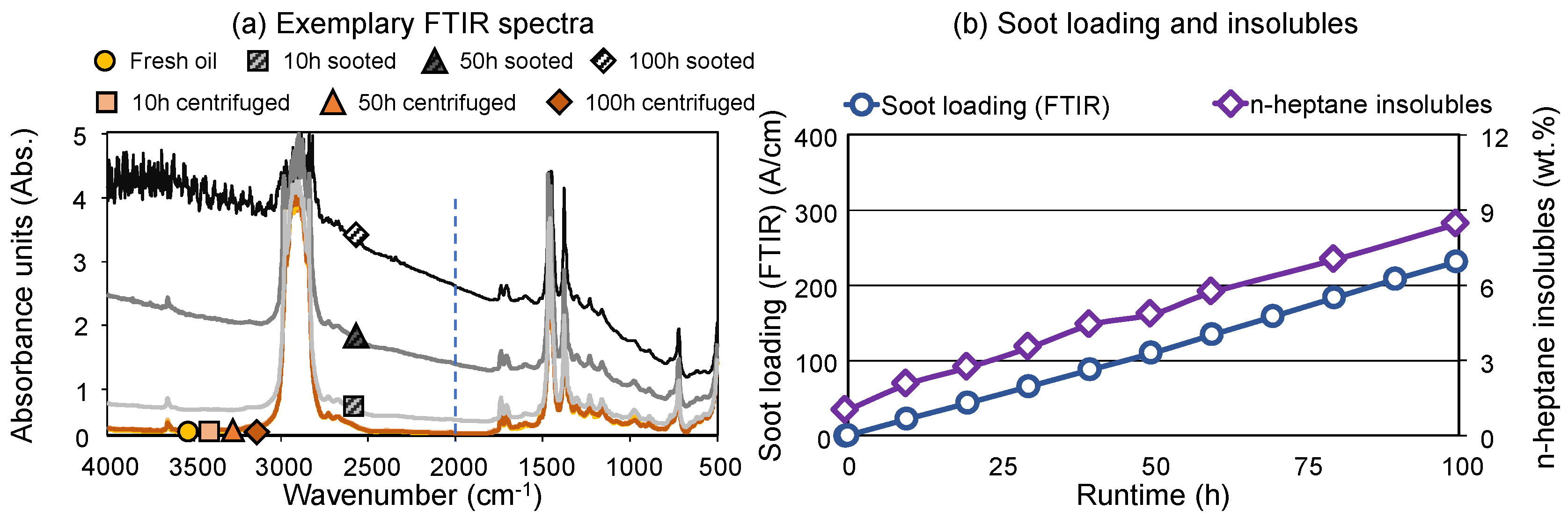
Figure 2.
(a-b) Oxidation and nitration of the sooted and centrifuged oils; (c-d) Residual additive content in the sooted and centrifuged oils relative to the fresh oil; (e-f) NN and TBN of the sooted and centrifuged oils.
Figure 2.
(a-b) Oxidation and nitration of the sooted and centrifuged oils; (c-d) Residual additive content in the sooted and centrifuged oils relative to the fresh oil; (e-f) NN and TBN of the sooted and centrifuged oils.
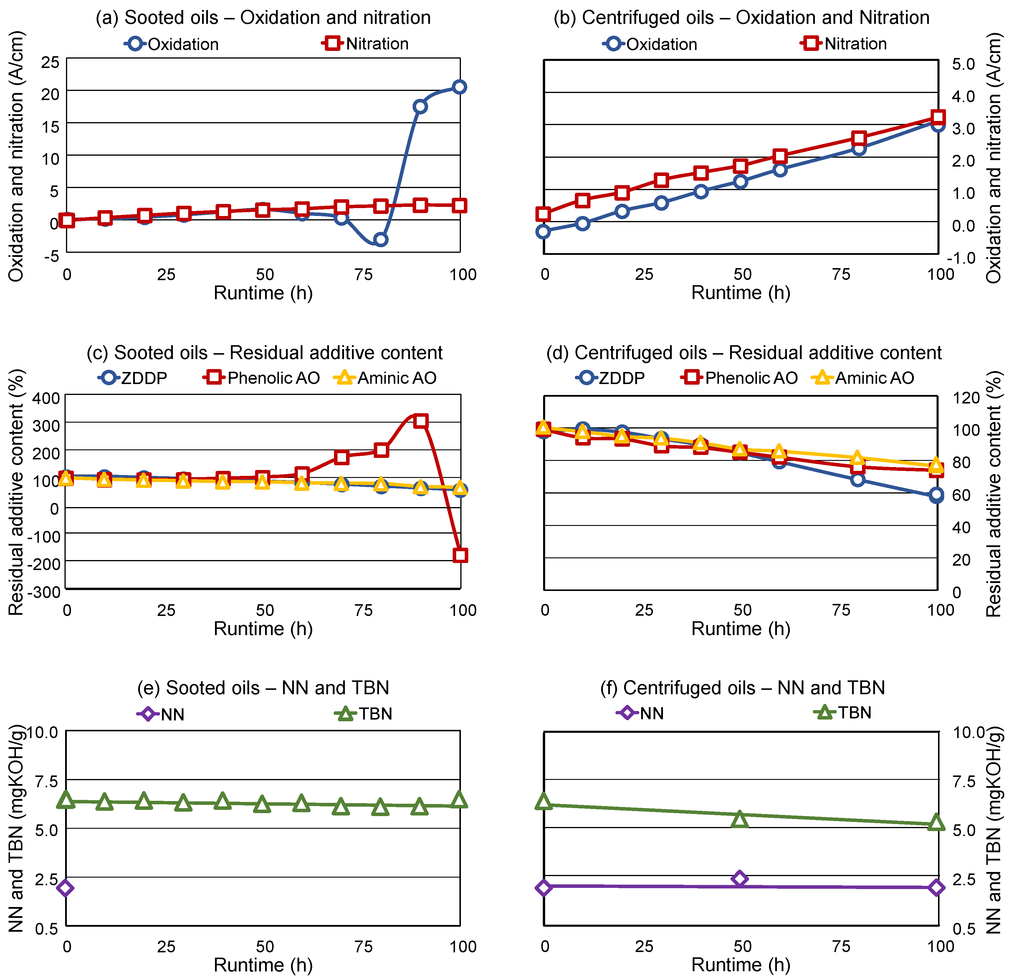
Figure 3.
(a-b): Dynamic viscosity of the sooted and centrifuged samples; (c-d): Shear-rate dependency of the viscosity of the final sooted and centrifuged sample.
Figure 3.
(a-b): Dynamic viscosity of the sooted and centrifuged samples; (c-d): Shear-rate dependency of the viscosity of the final sooted and centrifuged sample.
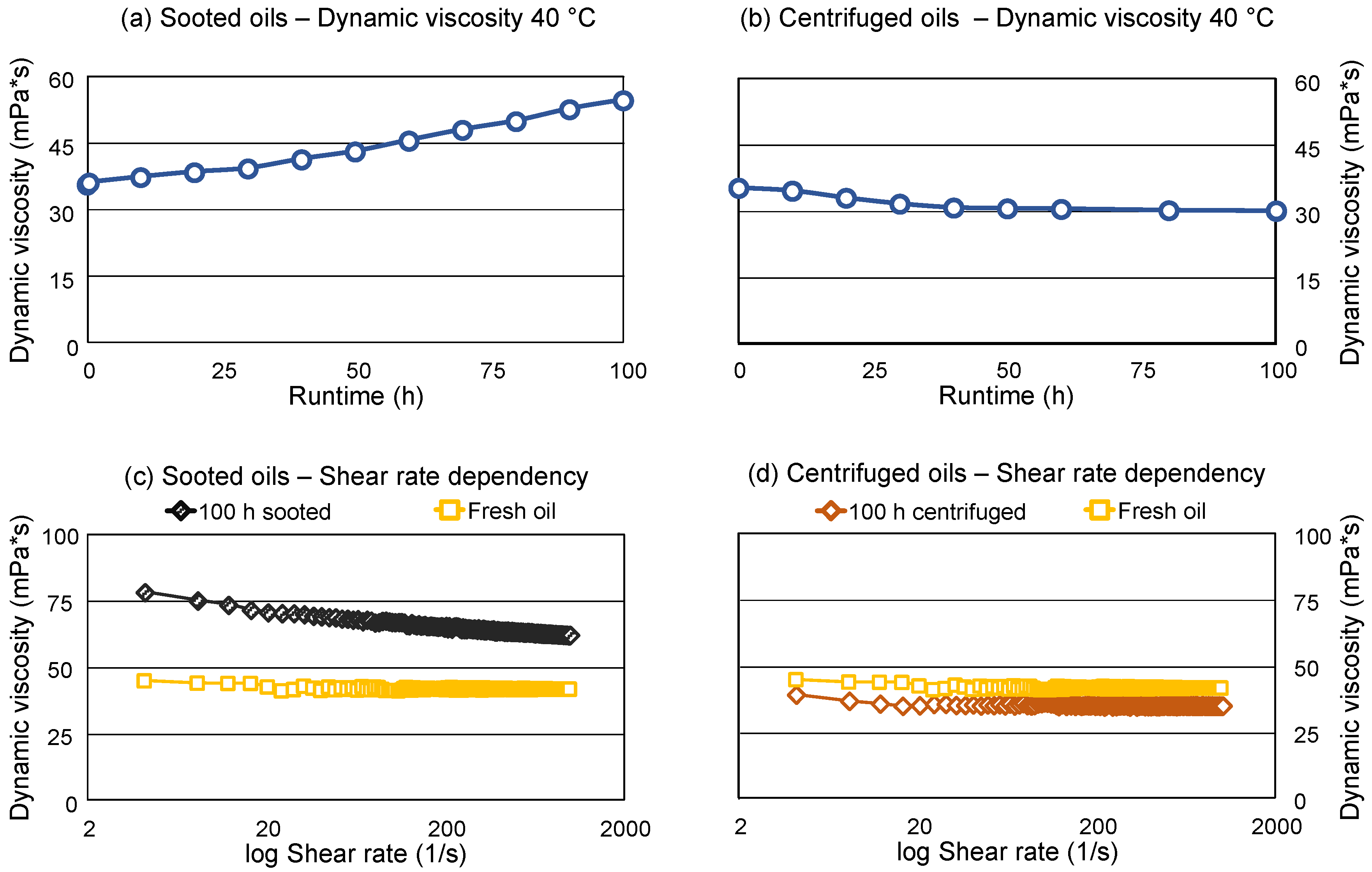
Figure 4.
(a) Elemental composition of the sooted oils; (b) Water content of the sooted oils.
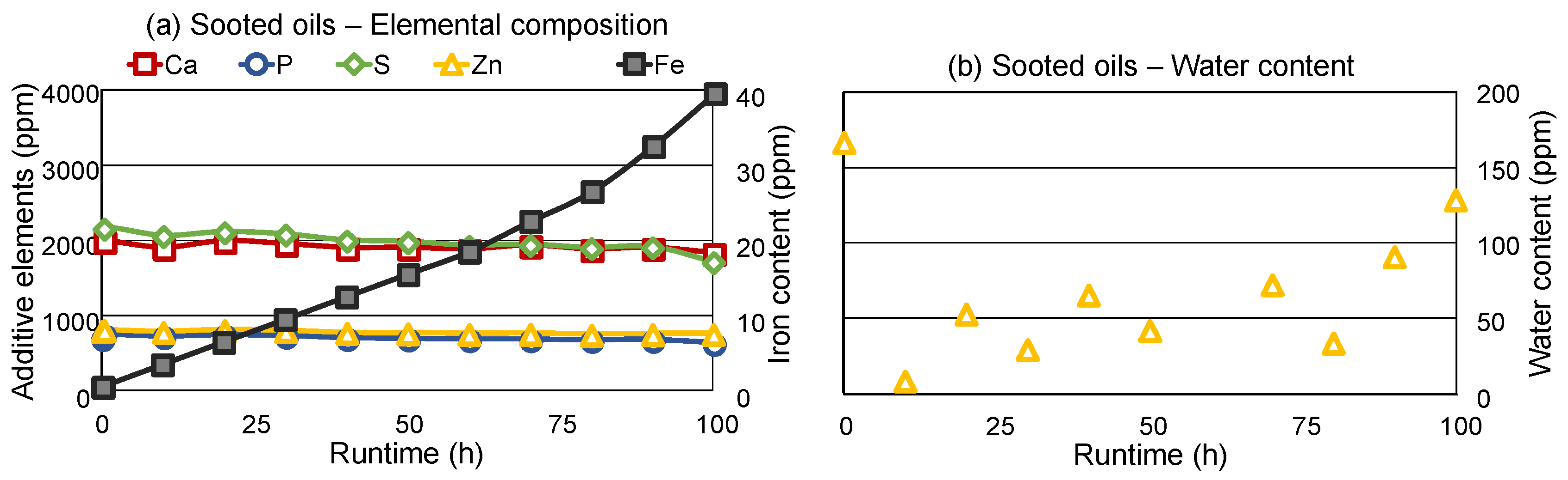
Figure 5.
Additive structures in the fresh, final sooted and final centrifuged oil samples. (a) Aminic antioxidants (positive ion mode); (b) Sulfonate detergents (negative ion mode); (c) Salicylate detergents (negative ion mode); (d) ZDDP antiwear (negative ion mode).
Figure 5.
Additive structures in the fresh, final sooted and final centrifuged oil samples. (a) Aminic antioxidants (positive ion mode); (b) Sulfonate detergents (negative ion mode); (c) Salicylate detergents (negative ion mode); (d) ZDDP antiwear (negative ion mode).
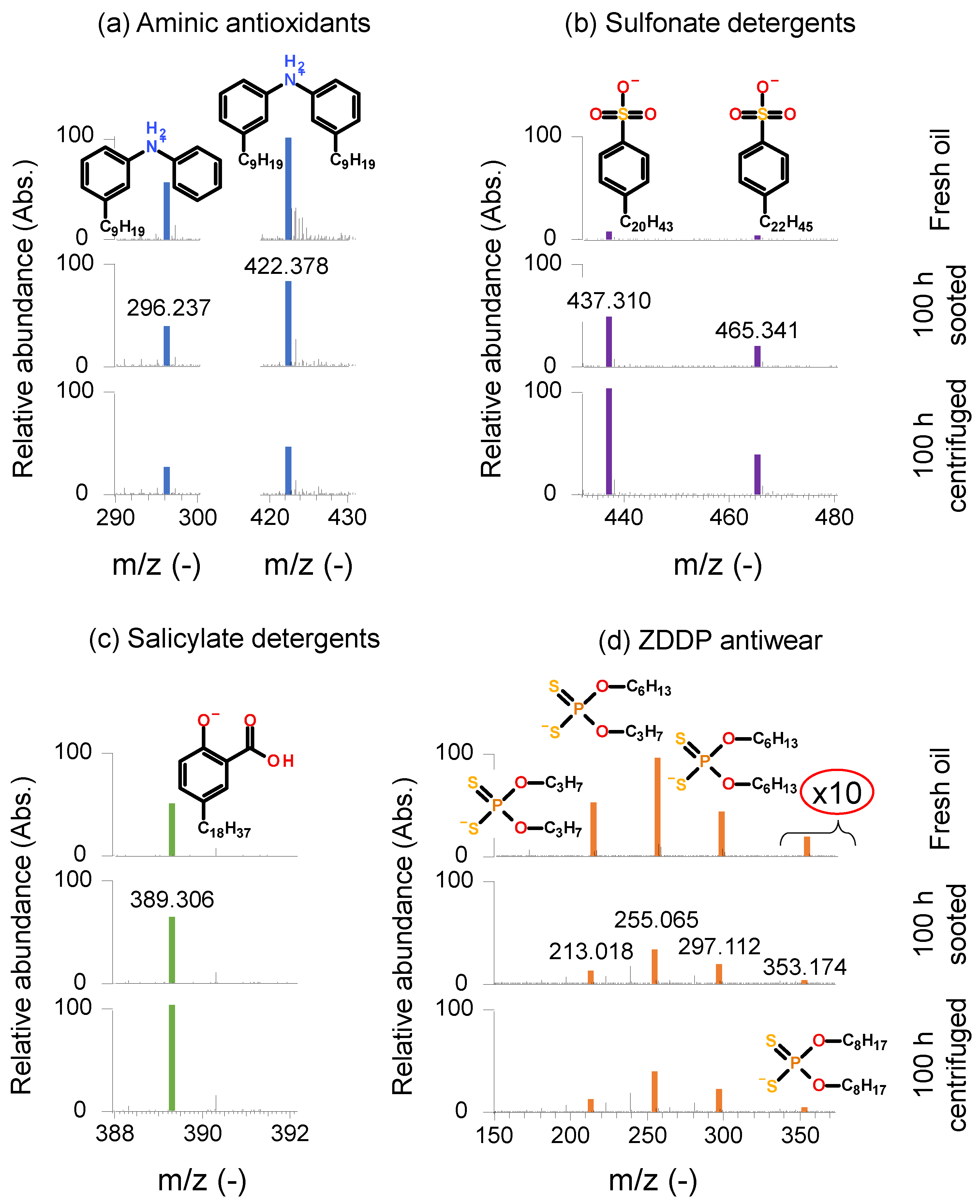
Figure 6.
ZDDP Degradation products in the fresh, final sooted and final centrifuged oil samples. (a) Dialkyl thiophosphates and dialkyl phosphates (negative ion mode); (b) alkyl phosphates (negative ion mode); (c) Reaction products of salicylate detergents and dialkyl dithiophosphates (negative ion mode); (d) Reaction products of salicylate detergents and sulfuric acid (negative ion mode).
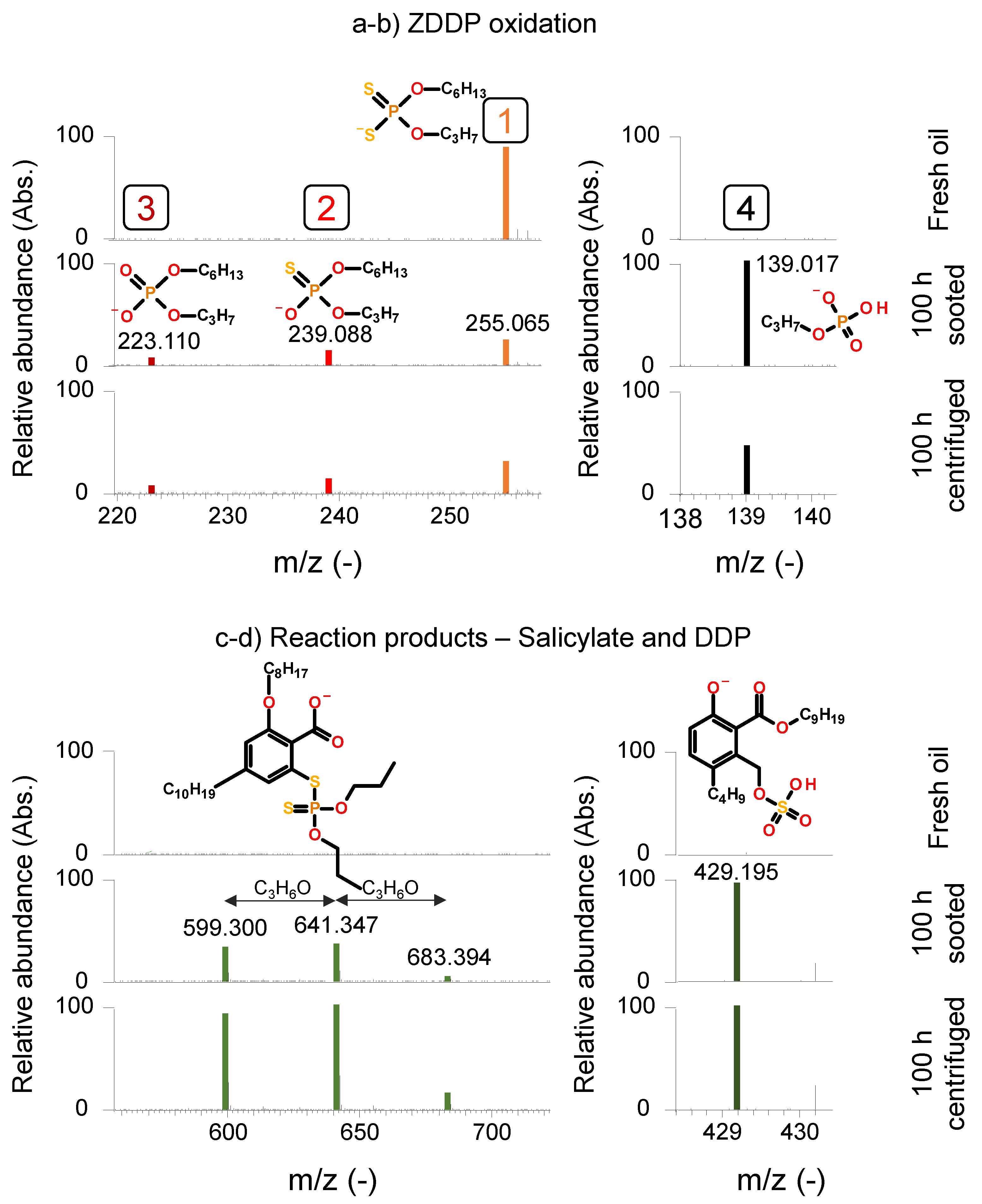
Figure 7.
(a) Additive elements in the isolated soot samples via EDX; Identified additives and degradation products in the soot extracts via HR-MS; (b) aminic AOs (positive ion mode); (c) sulfonate detergent (negative ion mode); (d) phenolic antioxidants (negative ion mode); (e) ZDDP and degradation products (negative ion mode).
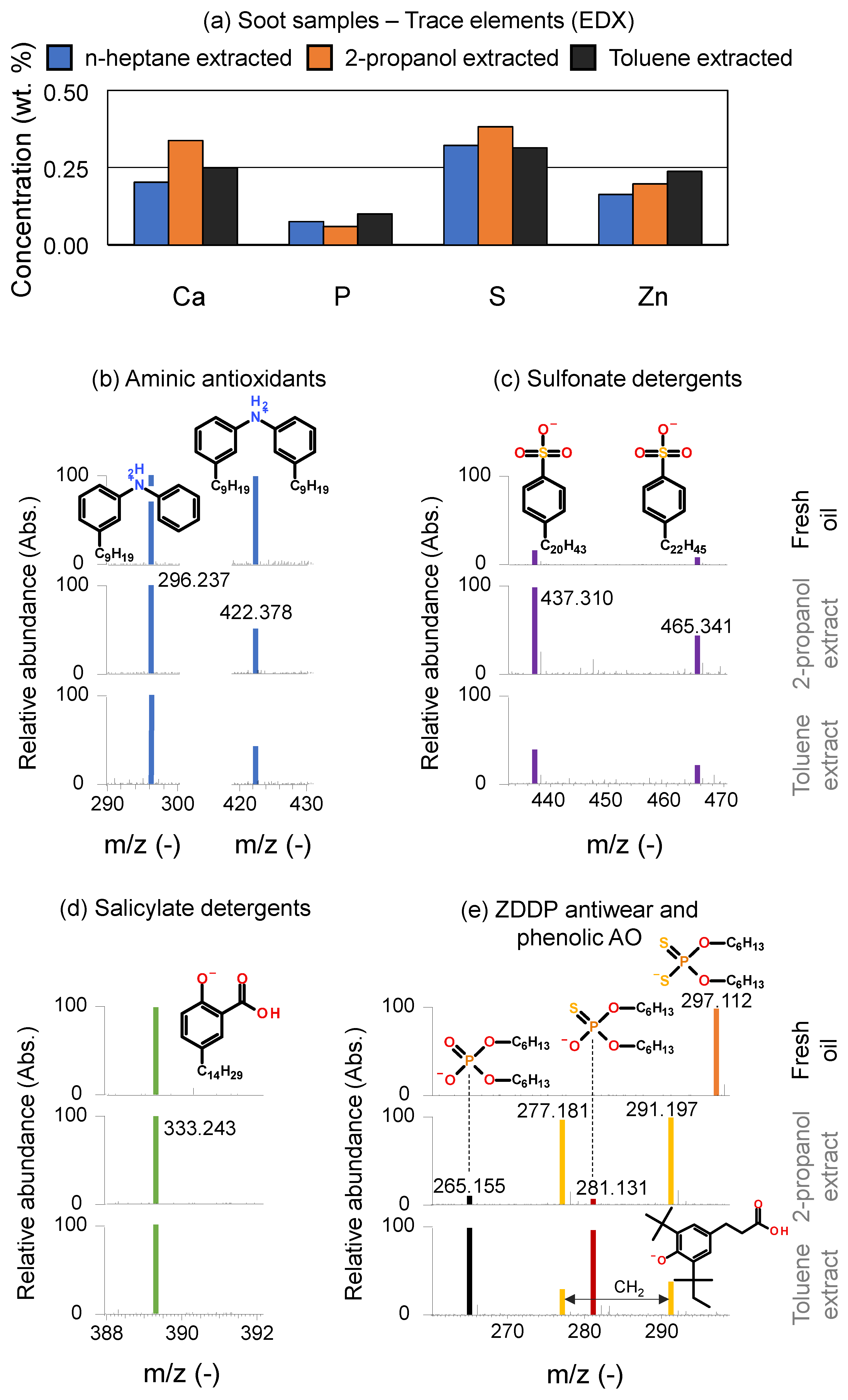
Figure 8.
Friction and wear properties of the fresh, sooted, and centrifuged engine oil samples. (a) Exemplary CoF curves; (b) Average CoF; (c) Wear scar area on SRV® ball; (d) Wear scar area on SRV® disc; (e) Wear volume on SRV® ball; (f) Wear volume SRV® disc. All error bars are corresponding to ± 1 standard deviation.
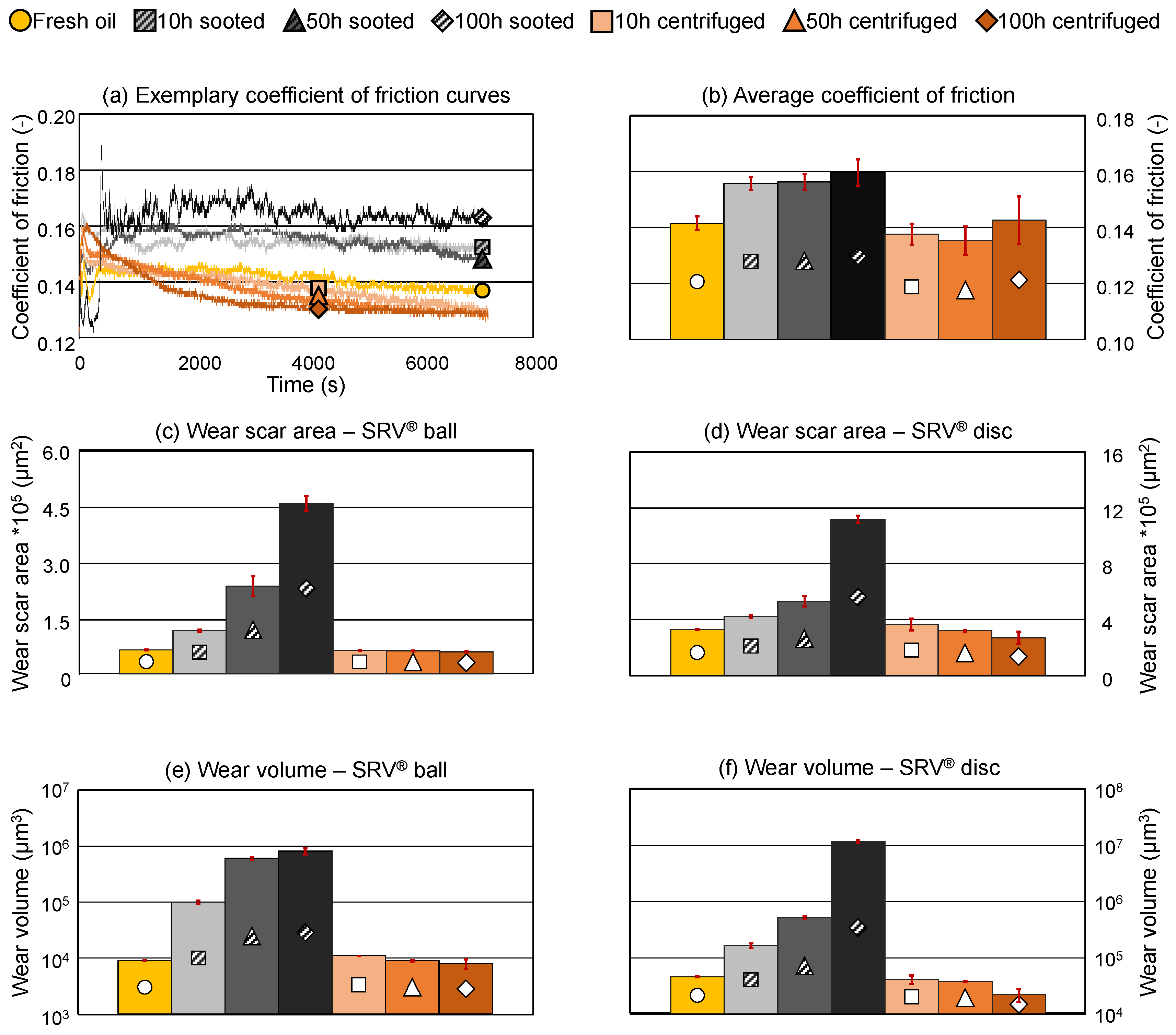
Figure 9.
Tribofilm composition on the SRV® discs. (a) Schematic representation according to [16]; (b) Iron; (c) Calcium; (d) Phosphor; (e) Sulfur (Sulfides and sulfates); (f) Zinc.
Figure 9.
Tribofilm composition on the SRV® discs. (a) Schematic representation according to [16]; (b) Iron; (c) Calcium; (d) Phosphor; (e) Sulfur (Sulfides and sulfates); (f) Zinc.
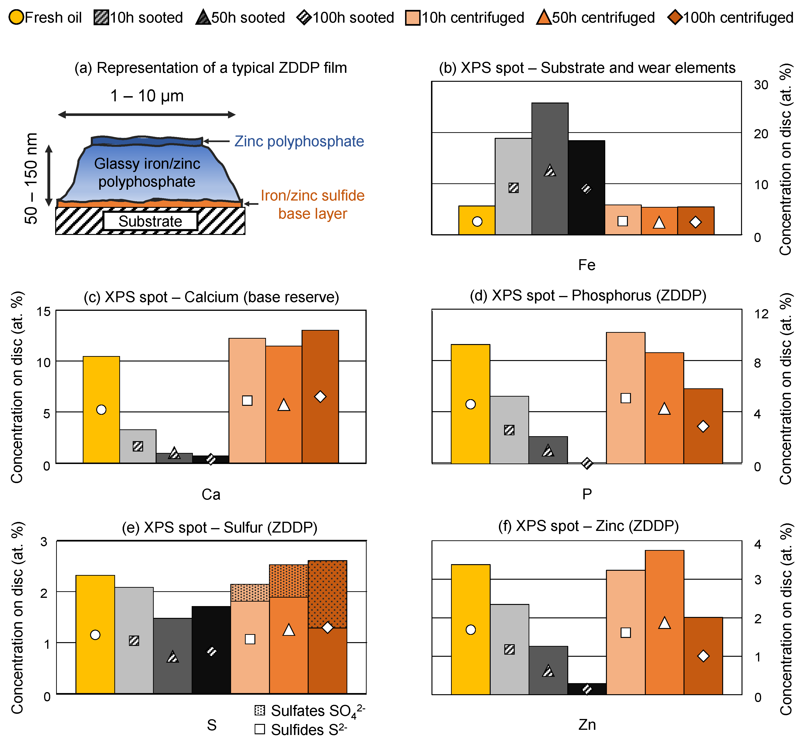
Figure 10.
XPS depth profiles of selected sooted and centrifuged samples—Tribofilm thickness estimation. (a) Iron (substrate); (b): Calcium (base reserve additive in tribofilm).
Figure 10.
XPS depth profiles of selected sooted and centrifuged samples—Tribofilm thickness estimation. (a) Iron (substrate); (b): Calcium (base reserve additive in tribofilm).
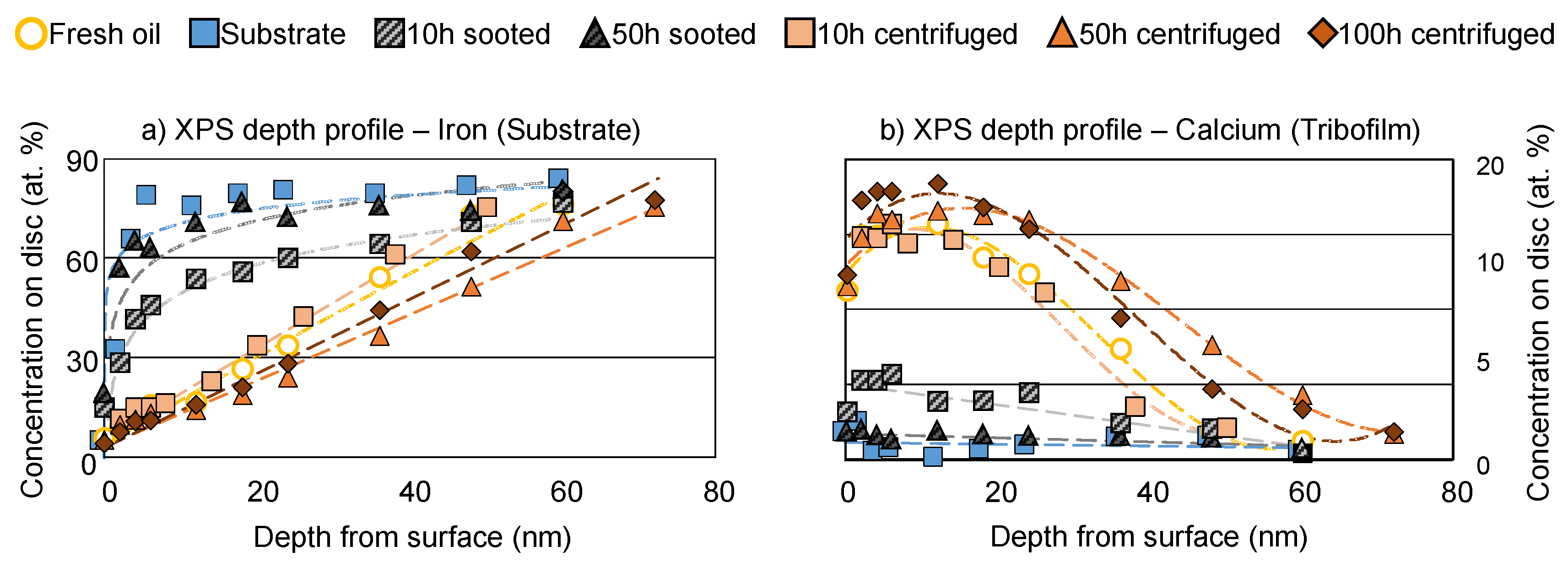
Figure 11.
Wear scars and surface maps of the fresh, the 50 h sooted and the 50 h centrifuged oils. (a) True color images; (b) Surface topography; (c) Calcium; (d) Phosphor; (e) Organic phosphates; (f) Sulfides; (g) Zinc, (h) Metal oxides; (i) Metallic iron.
Figure 11.
Wear scars and surface maps of the fresh, the 50 h sooted and the 50 h centrifuged oils. (a) True color images; (b) Surface topography; (c) Calcium; (d) Phosphor; (e) Organic phosphates; (f) Sulfides; (g) Zinc, (h) Metal oxides; (i) Metallic iron.
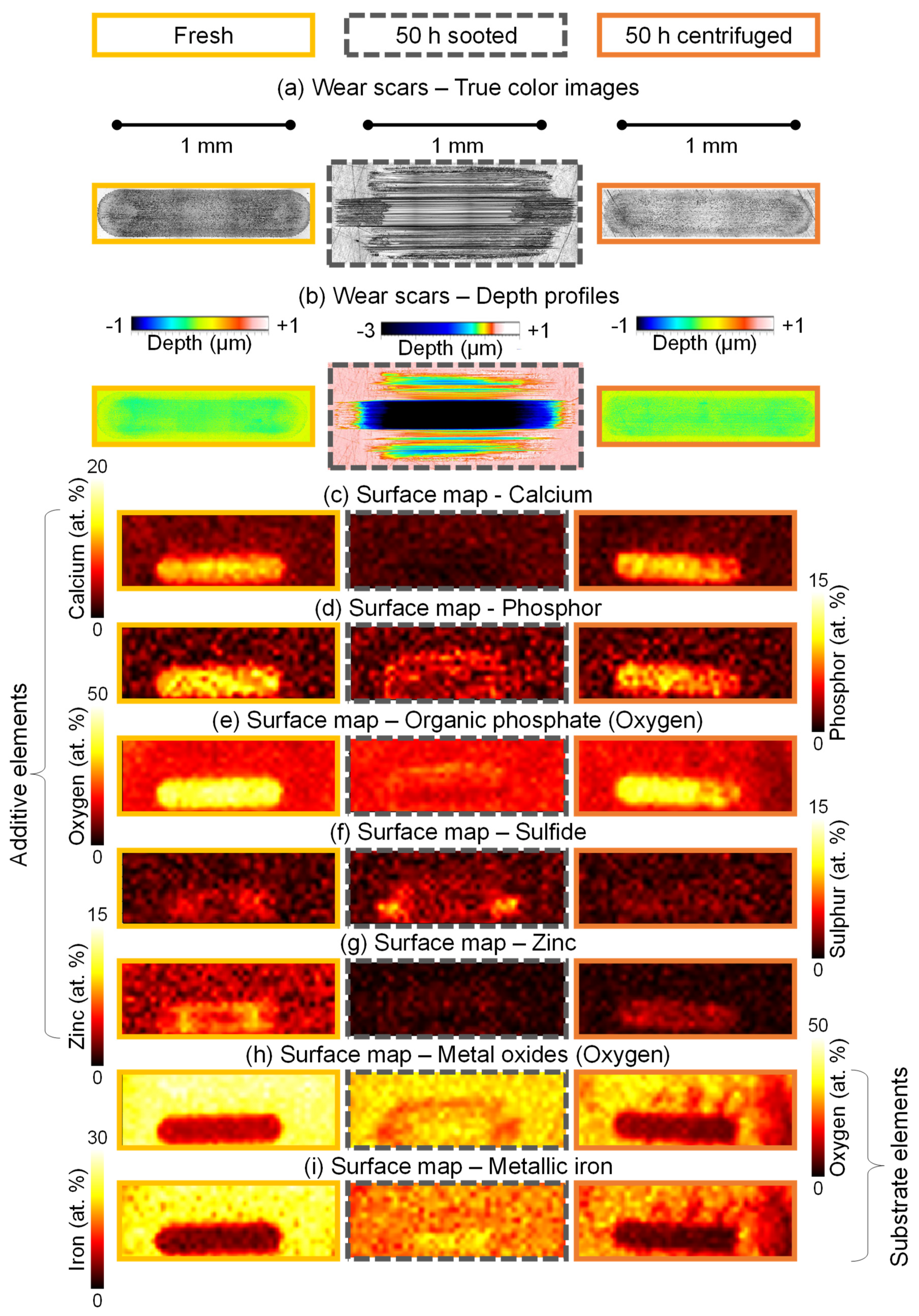
Figure 12.
Schematic representation of the theorized tribocorrosion-based wear mechanism of soot.
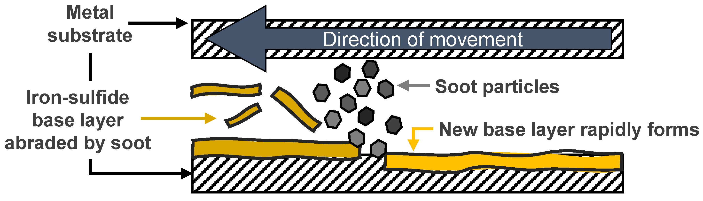

Table 1.
Properties of the utilized test engine.
| Test engine | |
|---|---|
| Manufacturer | Cummins |
| Model | ISB |
| Configuration | Inline 6 |
| Displacement (L) | 5.9 |
| Aspiration | Turbocharged |
| Fuel system | High-pressure common rail direct injection |
| Fuel | According to ASTM D975 [36] |
| Injection timing | Retarded to -15° |
| Exhaust system | Cooled exhaust gas recirculation (EGR) |
Table 2.
Parameters of the engine operation during the dynamometer test.
| Engine operating parameters |
Engine speed (RPM) | Torque (NM) | Fuel rate (kg/h) | Fuel temp. (°C) | Coolant outlet temp. (°C) | Coolant pressure (kPa) | Intake manifold pressure (kPa) |
|---|---|---|---|---|---|---|---|
| Average | 1600 | 419 | 20 | 40 | 99 | 104 | 217 |
| Min. | 1597 | 406 | 19 | 33 | 98 | 103 | 206 |
| Max. | 1603 | 443 | 21 | 40 | 100 | 106 | 226 |
|
Engine operating parameters |
Intake manifold temp. (°C) | Inlet air temp. (°C) | Turbo outlet temp. (°C) | Oil temp. (pan) (°C) | Oil pressure (kPa) | Intake restriction (kPa) | Exhaust back pressure (kPa) |
| Average | 68 | 30 | 152 | 110 | 183 | 2.0 | 7.4 |
| Min. | 66 | 25 | 122 | 109 | 151 | 0.6 | 5.4 |
| Max. | 70 | 34 | 160 | 116 | 204 | 2.2 | 7.9 |
Table 3.
Properties of the utilized engine oil.
| Engine oil | |
|---|---|
| NN (mgKOH/g) | 1.9 |
| TBN (mgKOH/g) | 6.4 |
| Dynamic viscosity at 40 °C (mPa*s) | 35.8 |
| Dynamic viscosity at 100 °C (mPa*s) | 6.1 |
| Density at 40 °C (g/mL) | 0.824 |
| Density at 100 °C (g/mL) | 0.786 |
| Viscosity index (-) | 147.1 |
| Ca content (ppm) | 1900 |
| P content (ppm) | 700 |
| S content (ppm) | 1900 |
| Zn content (ppm) | 800 |
Table 4.
Applied conventional oil analysis methods.
| Parameter | Analytical technique | Equipment |
|---|---|---|
| Oxidation | FTIR at 1720 cm-1 (in-house method [33,34]) |
Tensor 27 FTIR spectrometer (Bruker, Ettlingen, Germany) Tensor 27 FTIR spectrometer (Bruker, Ettlingen, Germany) |
| Nitration | FTIR at 1630 cm-1 (DIN 51453 [37]) |
Tensor 27 FTIR spectrometer (Bruker, Ettlingen, Germany) |
| Soot loading | FTIR at 2000 cm-1 (ASTM E2412 [38]) |
Tensor 27 FTIR spectrometer (Bruker, Ettlingen, Germany) |
| Residual phenolic antioxidants | FTIR at 3650 cm-1 (in-house method [11,33]) |
Tensor 27 FTIR spectrometer (Bruker, Ettlingen, Germany) |
| Residual aminic antioxidants | FTIR at 1515 cm-1 (in-house method [11,33]) |
Tensor 27 FTIR spectrometer (Bruker, Ettlingen, Germany) |
| Residual ZDDP | FTIR at 1020–920 cm-1 (in-house method [11,33]) |
Tensor 27 FTIR spectrometer (Bruker, Ettlingen, Germany) |
| Water content | Indirect Karl-Fischer titration (DIN 51777 [39]) |
KF Coulometer 756 and an Oven Sample Processor 774 (Metrohm AG, Herisau, Switzerland) |
| Total base number (TBN) | Potentiometric indication titration (ISO 3771 [40]) | Titrator Basic Titrino 794 (Metrohm AG, Herisau, Switzerland) |
| Neutralization number (NN) | Color-indication titration (DIN 51558 [41]) |
- |
| Elemental composition | ICP-OES (in-house method [11,33]) |
iCAP 7400 ICP-OES Duo, ThermoFisher, Waltham, Massachusetts, USA) |
| Kinematic viscosity and density at 40°C and 100°C | Stabinger viscometer (ASTM D7042 [42]) |
Stabinger SVM 3000 Viscometer (Anton Paar GmbH, Graz, Austria) |
| Viscosity index (-) | Stabinger viscometer (ASTM D2270 [43]) |
Stabinger SVM 3000 Viscometer (Anton Paar GmbH, Graz, Austria) |
Table 5.
Configuration and operating conditions of the tribometrical experiments.
| Tribometrical experimental parameters | |||
|---|---|---|---|
| Oil quantity (mL) | ~ 0.1 | Temperature (°C) | 100 |
| Contact | Ball on disc | Mode | Oscillation |
| Material (ball and disc) | 100Cr6 | Hardness (ball and disc) | HRc 62 |
| Ball dimension (mm) | 10 | Disc dimensions (mm) | 10 x 7.9 |
| Load (N) | 50 | Stroke (mm) | 1 |
| Mean contact pressure (GPa) | 1.2 | Maximum contact pressure (GPa) | 1.7 |
| Frequency (Hz) | 30 | Duration (min) | 120 |
Disclaimer/Publisher’s Note: The statements, opinions and data contained in all publications are solely those of the individual author(s) and contributor(s) and not of MDPI and/or the editor(s). MDPI and/or the editor(s) disclaim responsibility for any injury to people or property resulting from any ideas, methods, instructions or products referred to in the content. |
© 2024 by the authors. Licensee MDPI, Basel, Switzerland. This article is an open access article distributed under the terms and conditions of the Creative Commons Attribution (CC BY) license (http://creativecommons.org/licenses/by/4.0/).
Copyright: This open access article is published under a Creative Commons CC BY 4.0 license, which permit the free download, distribution, and reuse, provided that the author and preprint are cited in any reuse.


