Submitted:
04 October 2024
Posted:
07 October 2024
You are already at the latest version
Abstract
Keywords:
1. Introduction
- (i)
- A new combined linear and DDC control methodology that uses the process control variables obtained from an experimental database built by a RBF methodology.
- (ii)
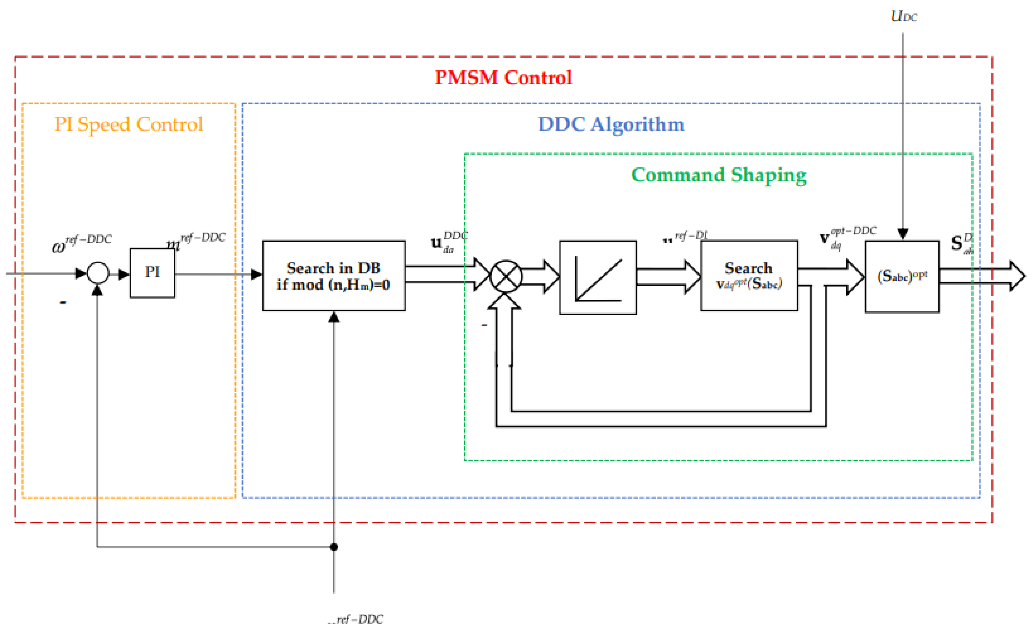
- In the case of the EDSs, the combined control methodology is in terms of an outer time domain PID control of speed and an inner implicit RBF control loop.
- (iii)
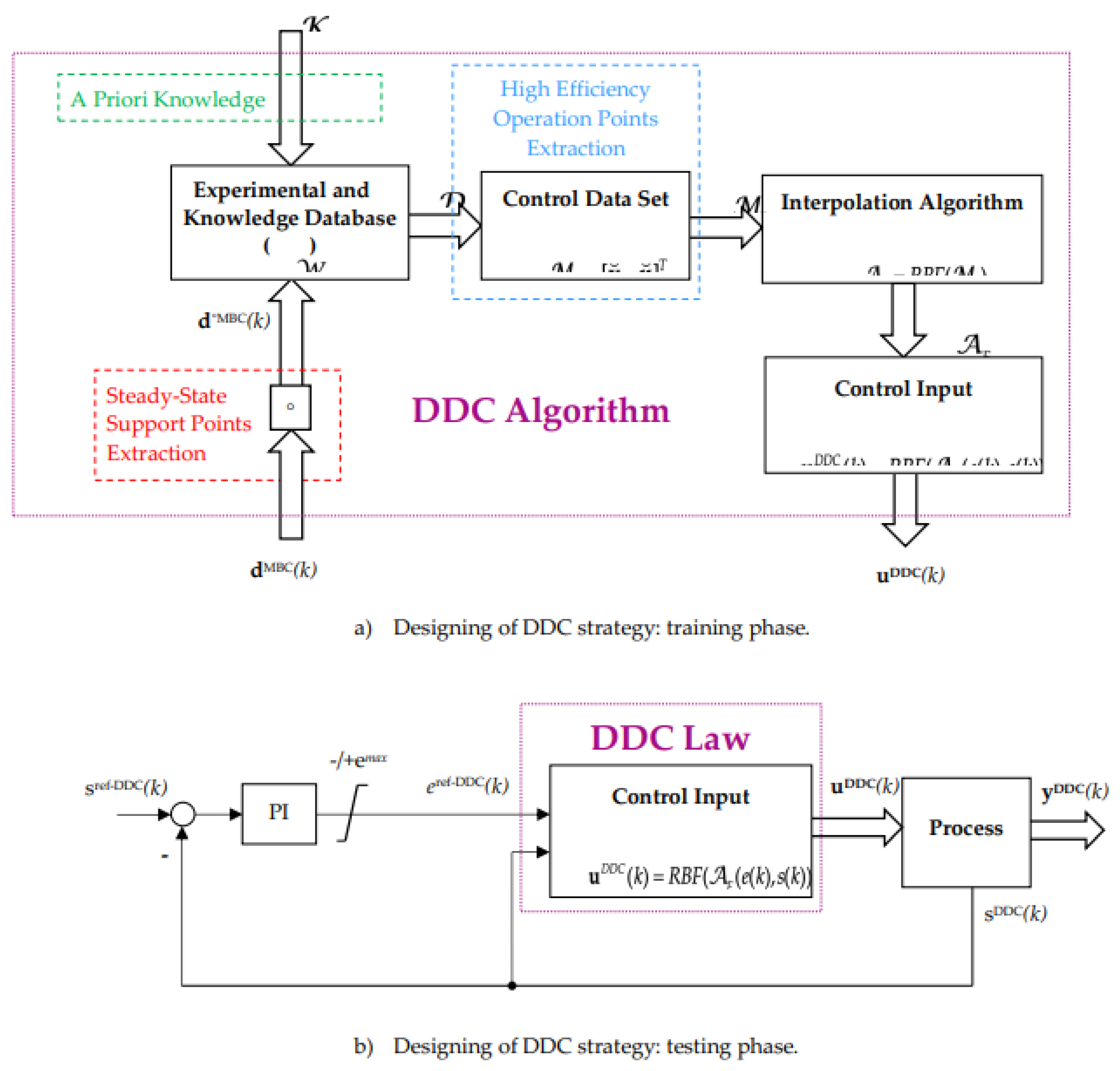
- The inner control loop is based on an experimental database, which contains the optimal controls corresponding to any speed and torque of process operation points. The control law is in implicit form that is a set a steady state process operation points.
- (iv)
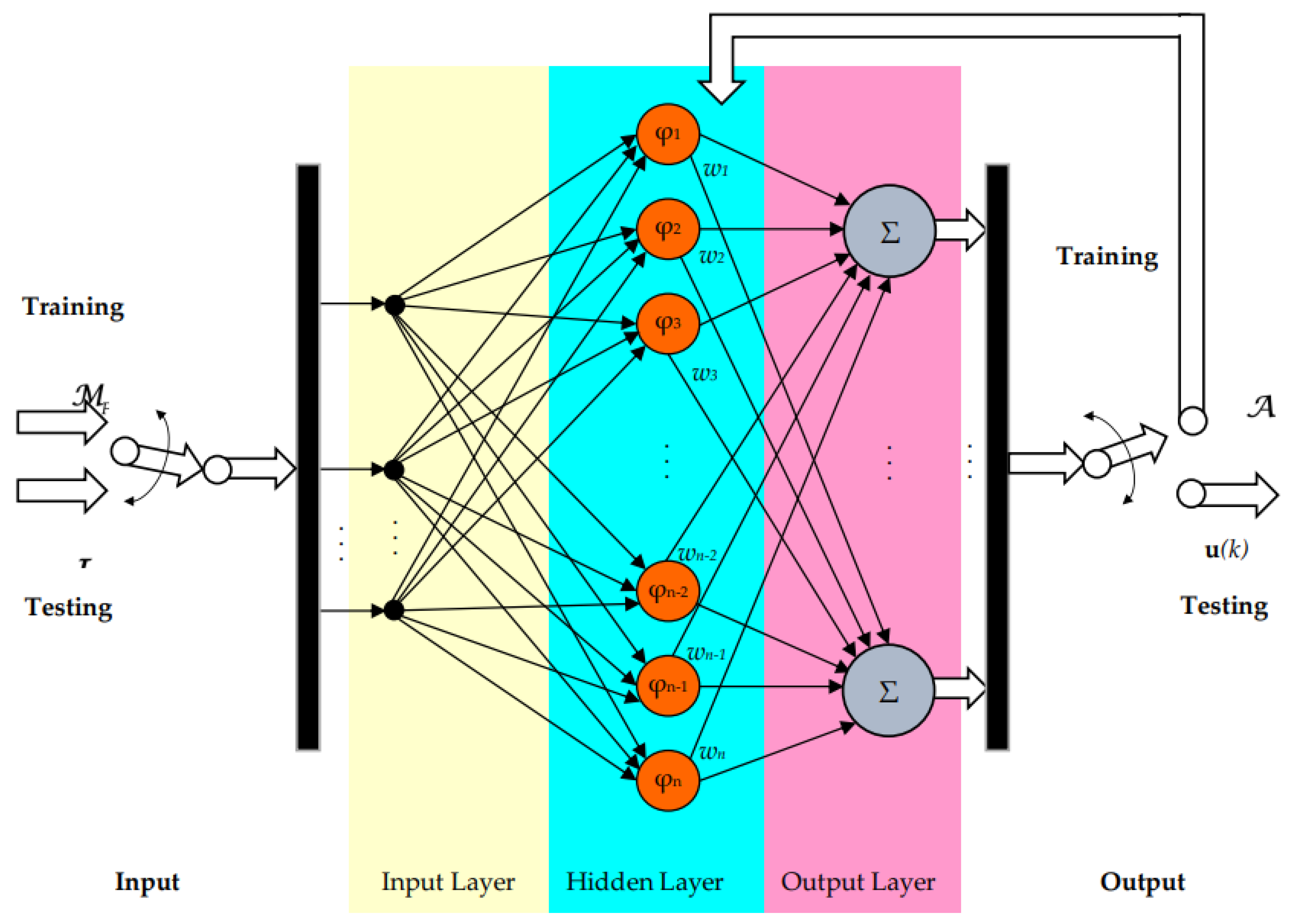
- The RBF methodology compresses the set of all admissible operation points by network architecture, with a few optimal data basis functions.
- (v)
- We present a novel control scheme in which the demanded effort by the PI controller and measured speed are the input for the RBF inner loop. The output of the inner loop is the inverter’s modulator input, which select the proper inverter’s voltage vector sequence of the invertor.
- (vi)
- The inner RBF control loop is adaptive, that is the inverter control is temperature dependent because the parameters of the process changes with motor is temperature.
2. Problem Statement. From Classical Physical Modeling of Energy Conversion Flow to Data Free Model Control
2.1. Problem Statement
2.2. The DDC Strategy of the Energy Conversion Process
3. The DDC of AC drive. Illustrative Case Study: The DDC of a PMSM Drive System
3.1. The DDC Principle of AC Drives
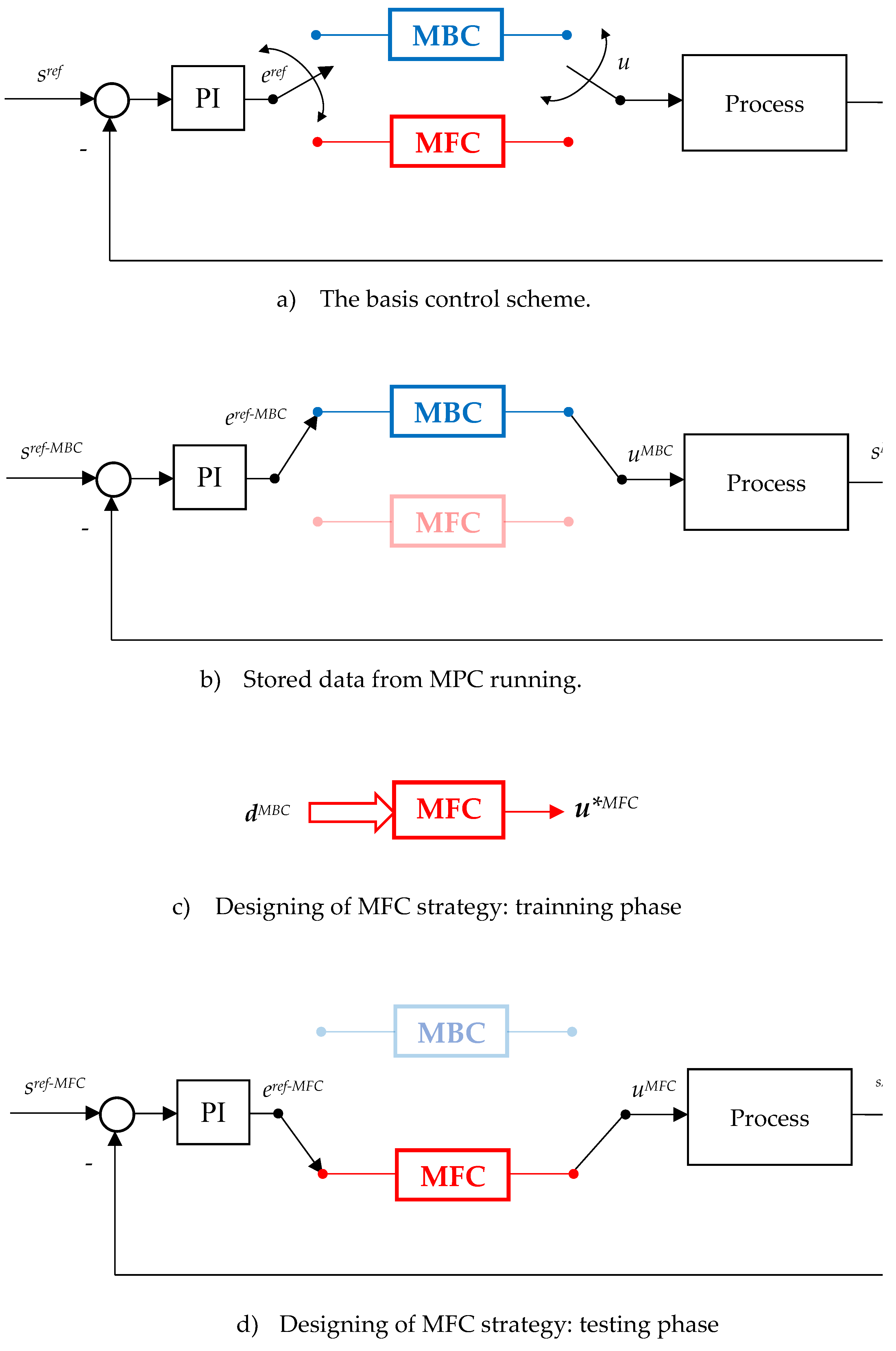
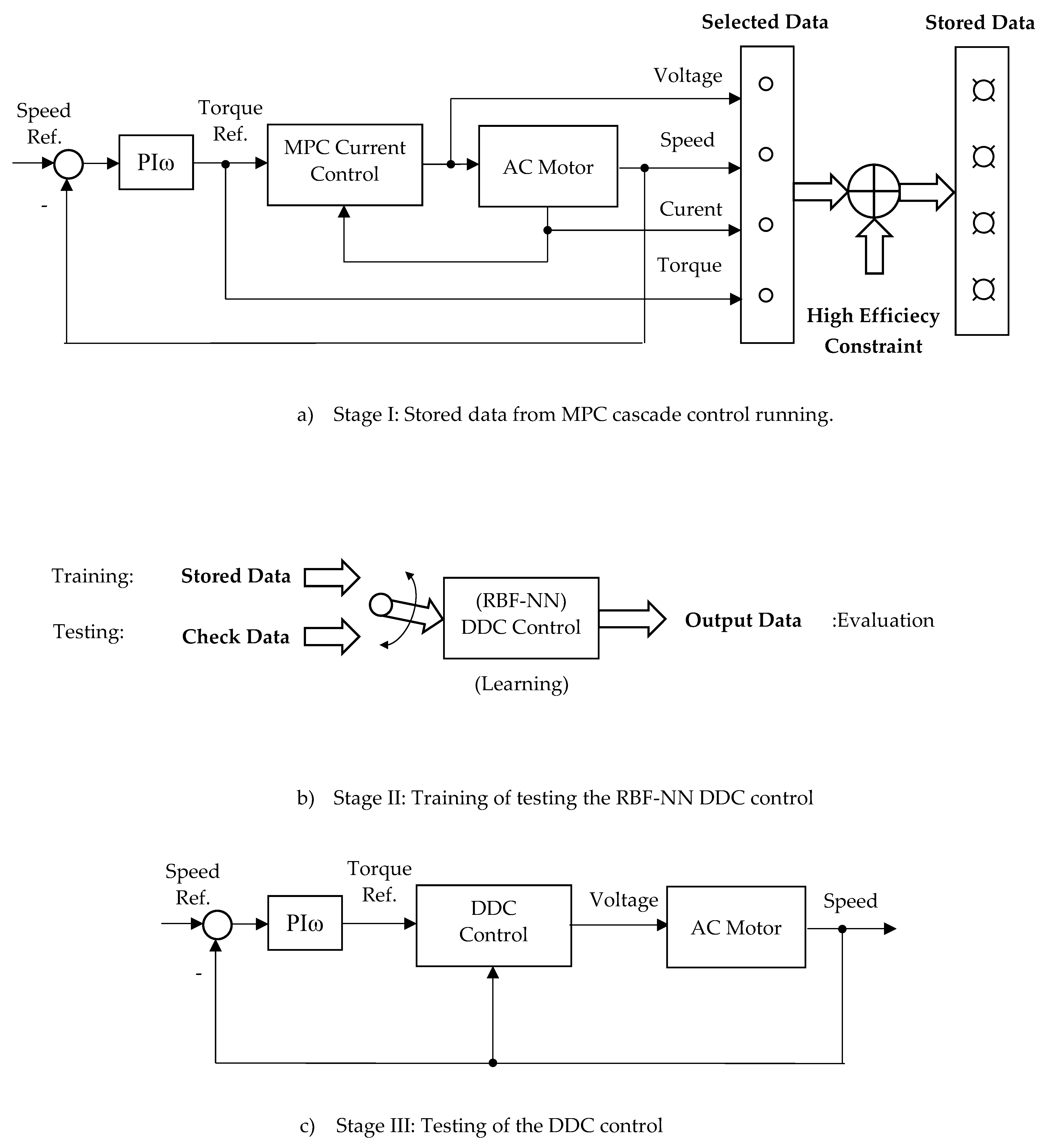
- a.
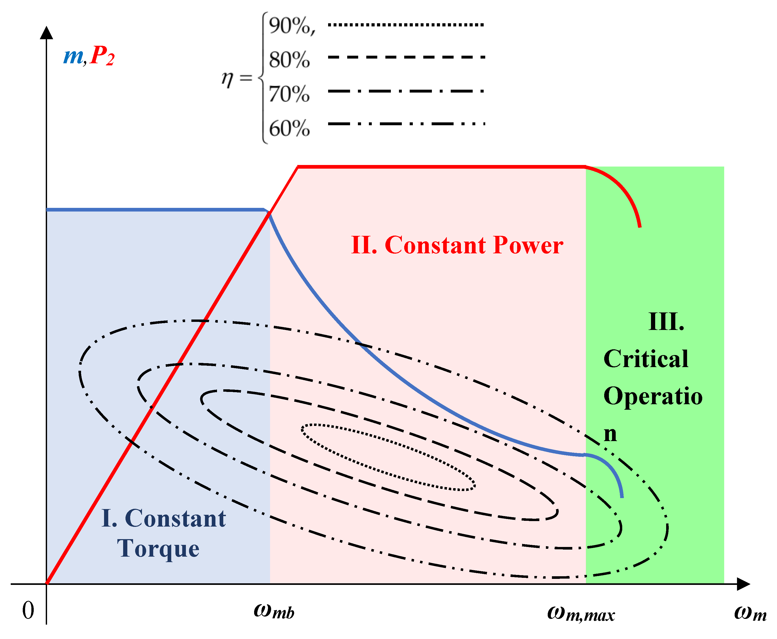
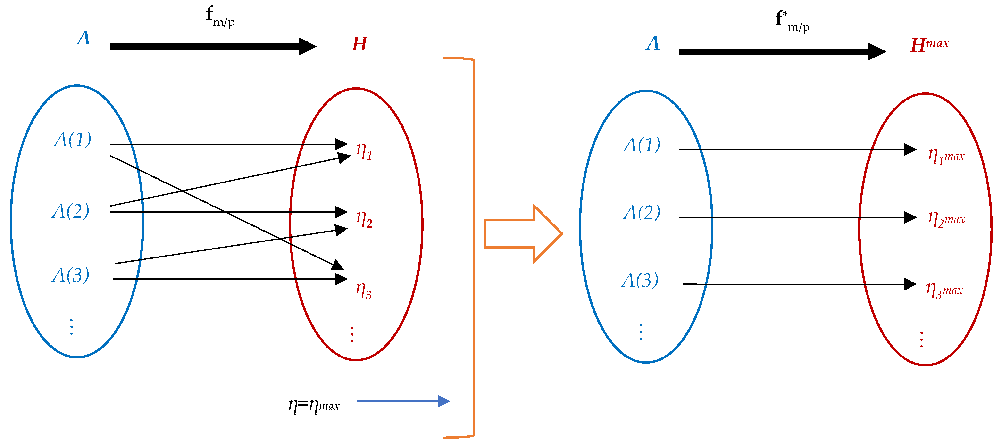
- Stage I: Stored data from MPC cascade control running. In this stage there are selected a limited data obtained from MPC cascade running in steady-state regime for: speed, torque, voltage and current. Further, from this there is imposed the constraint of high efficiency, resulting in the stored data;
- b.
- Stage II: Training of DDC strategy. The stored data obtained on the previous stage serves as a base in this training stage for DDC design which is done in a open structure. Usually, the stored data are numerically processed in the order to improve the main features: efficiency, robustness, tracking and disturbance rejection. This objectives are done by using a DB which offers multiple possibilities of data processing;
- c.
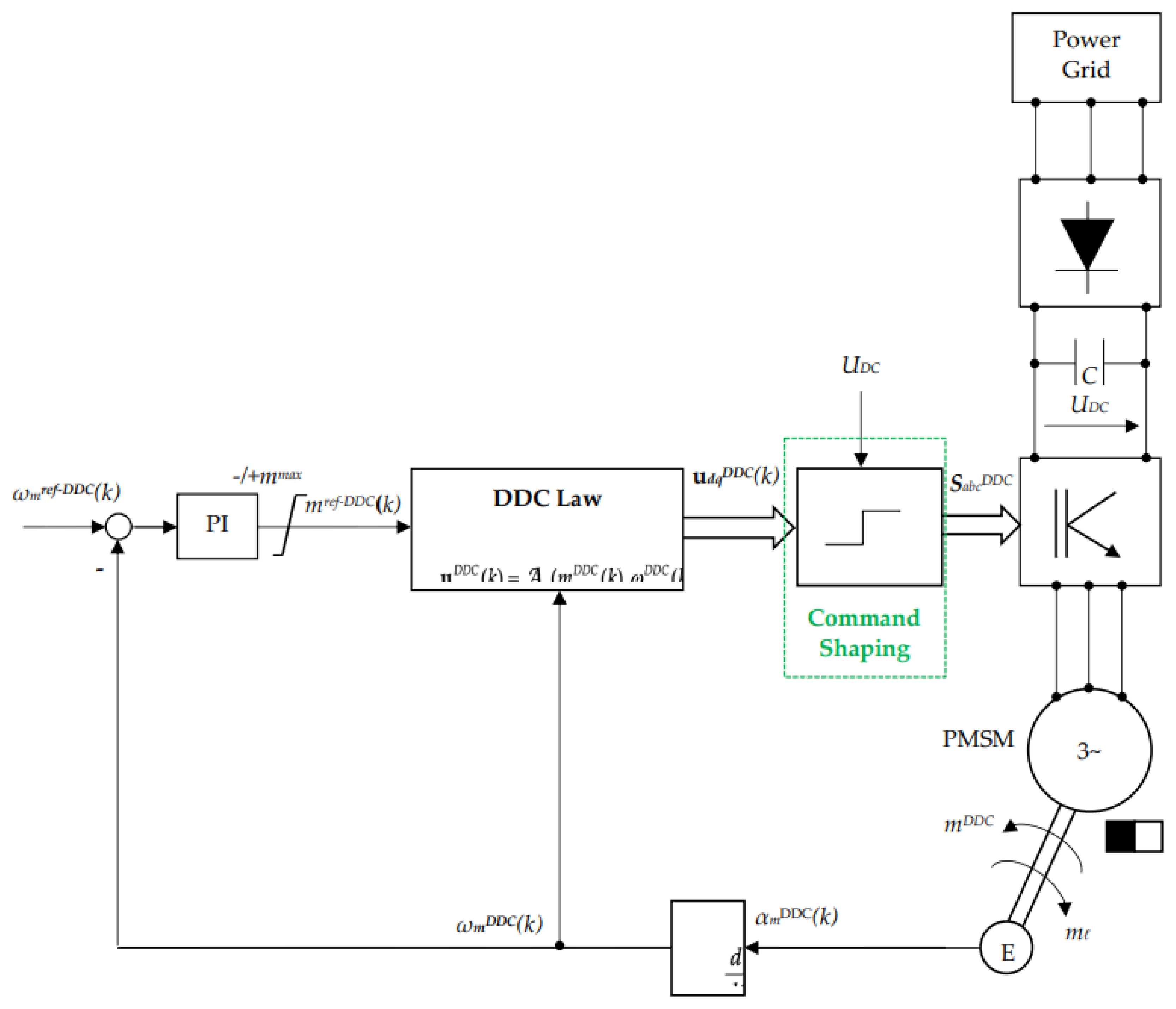
- Stage III: Testing of DDC method. Learning from the previous stage, the DDC strategy is able to operate in any point required by the application of AC drive. The DDC method are implemented with no cascade control structure as is shown in the figure.
3.2. DDC of the PMSM Drive System
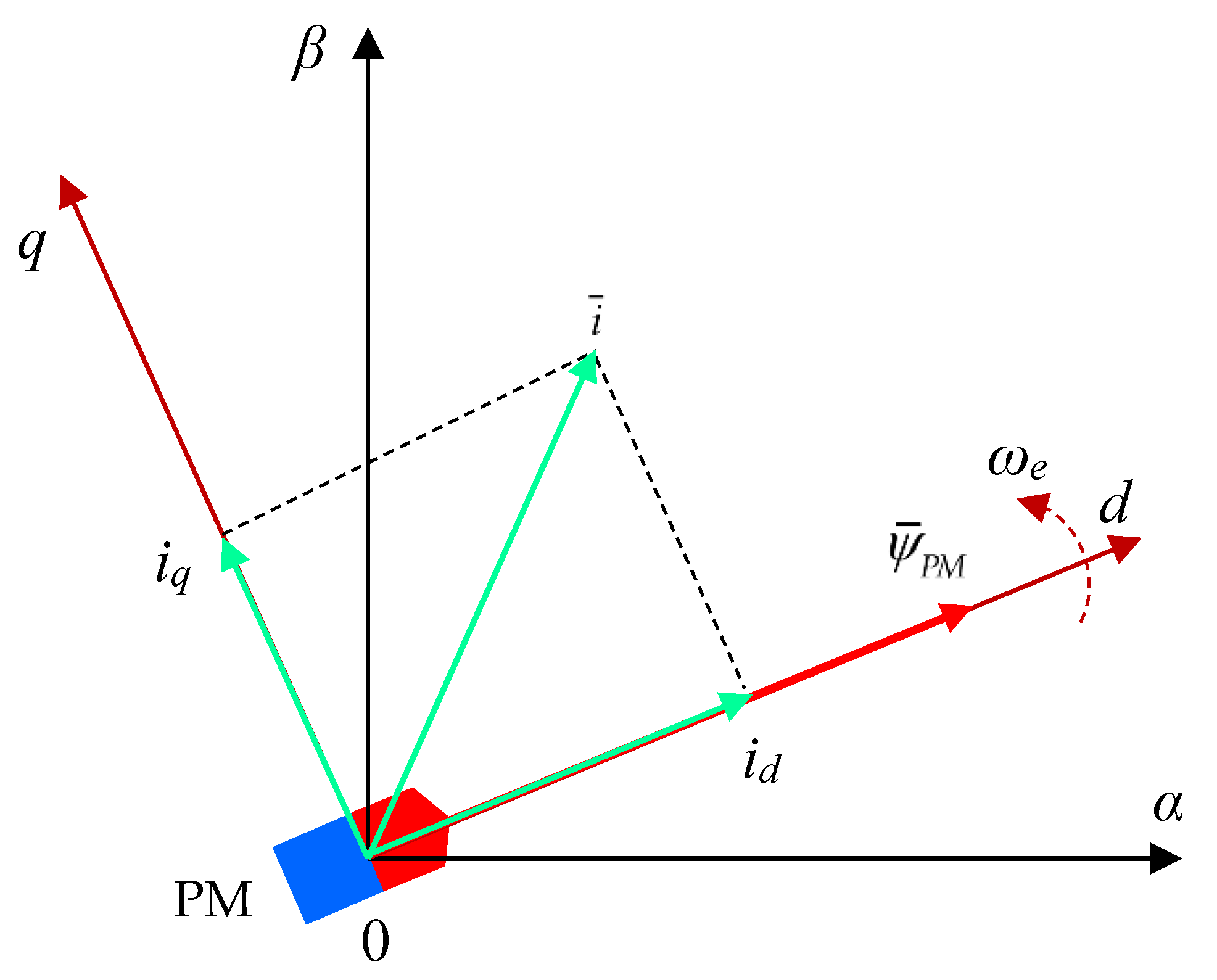
3.2.1. Plant Modeling: PMSM and Power Inverter
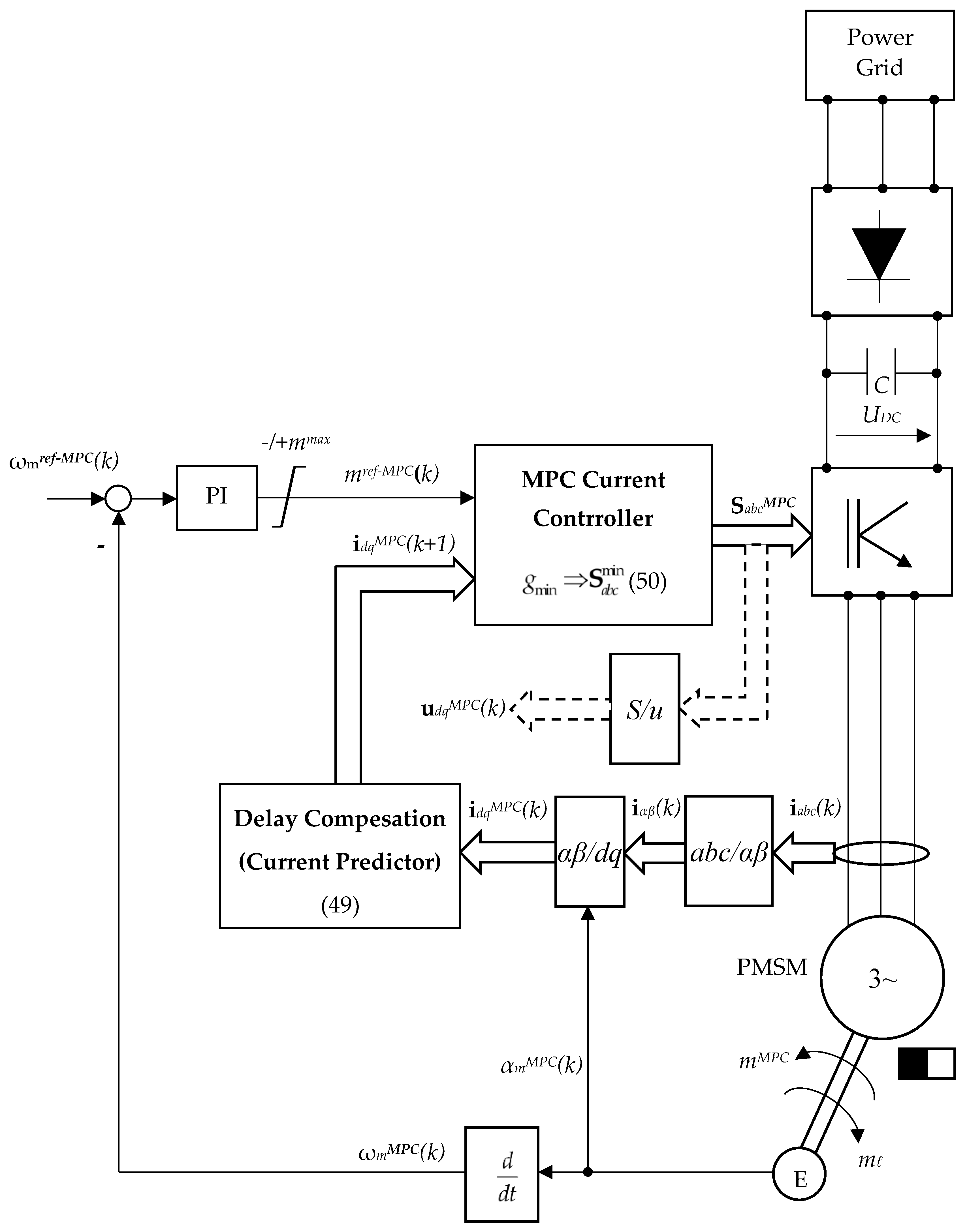
3.2.2. MPC with Finite Set
3.2.3. DDC Law of PMSM
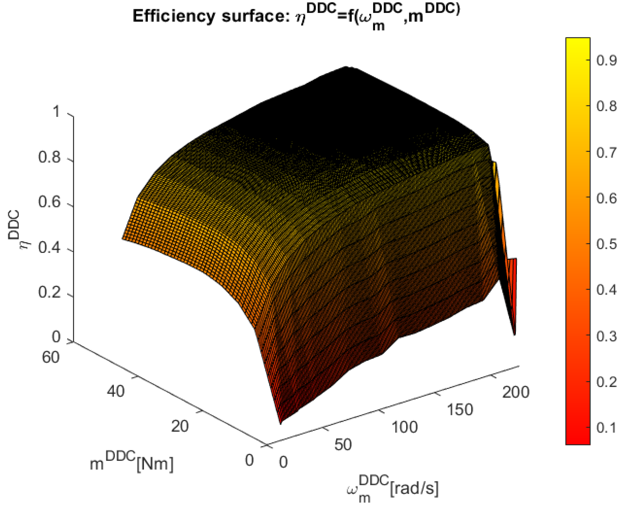
3.2.4. Design of the DDC Database
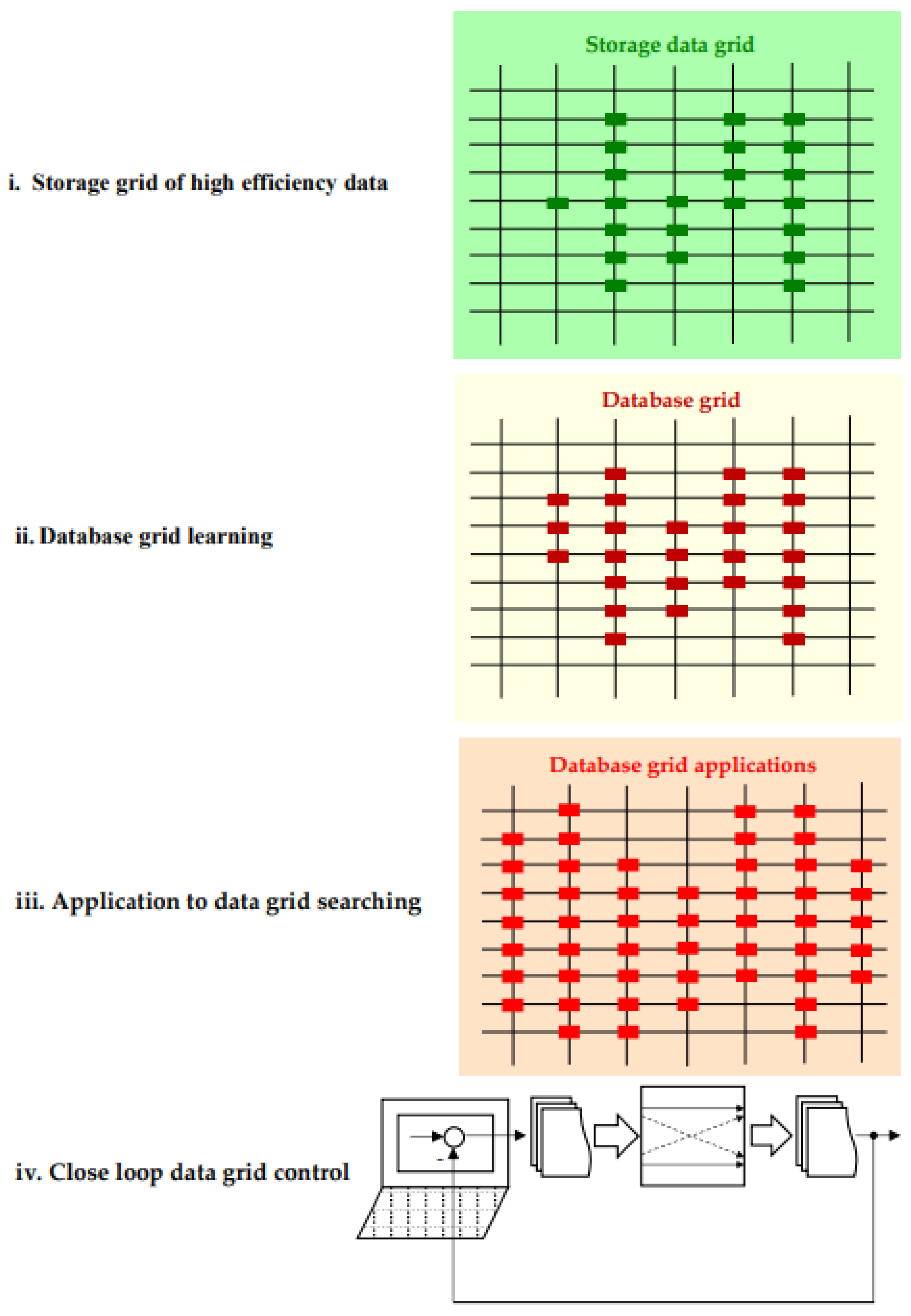
- I.
- Storage grid of high efficiency data. At this step there are collected the main data set in the steady-state regime and knowledge which corresponds to a high efficiency value stored in
- II.
- Database grid learning. The database sets are extended by a learning process, adding new points contained in the set:
- III.
- Application to data grid searching. It is checked that the added new points corresponds to the real operation for open loop applications.
- IV.
- Close loop data grid control. Finally, the designed database grid is introduced in the desired close loop application from Figure 16.
3.2.5. DDC Matlab Implementation
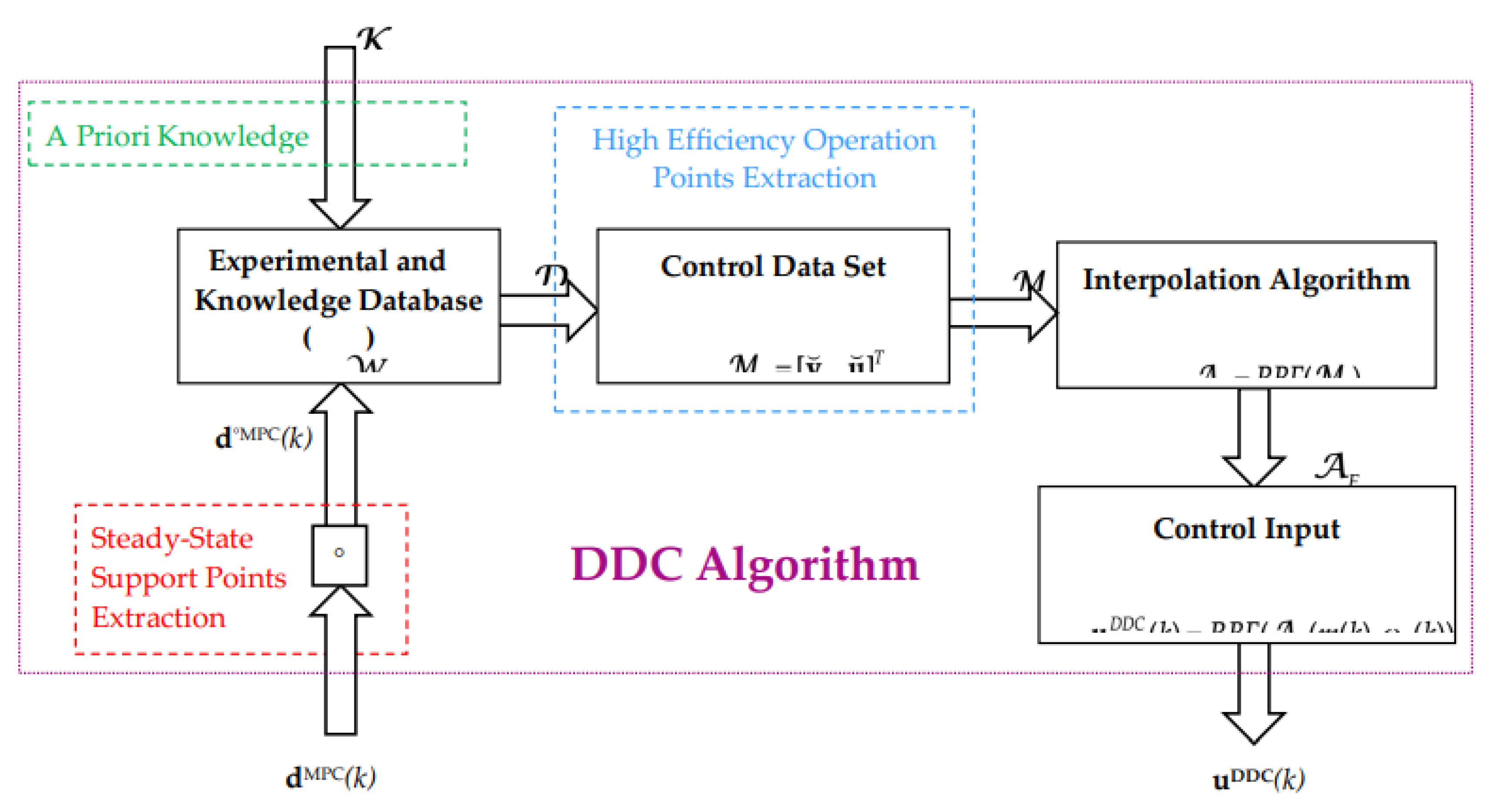
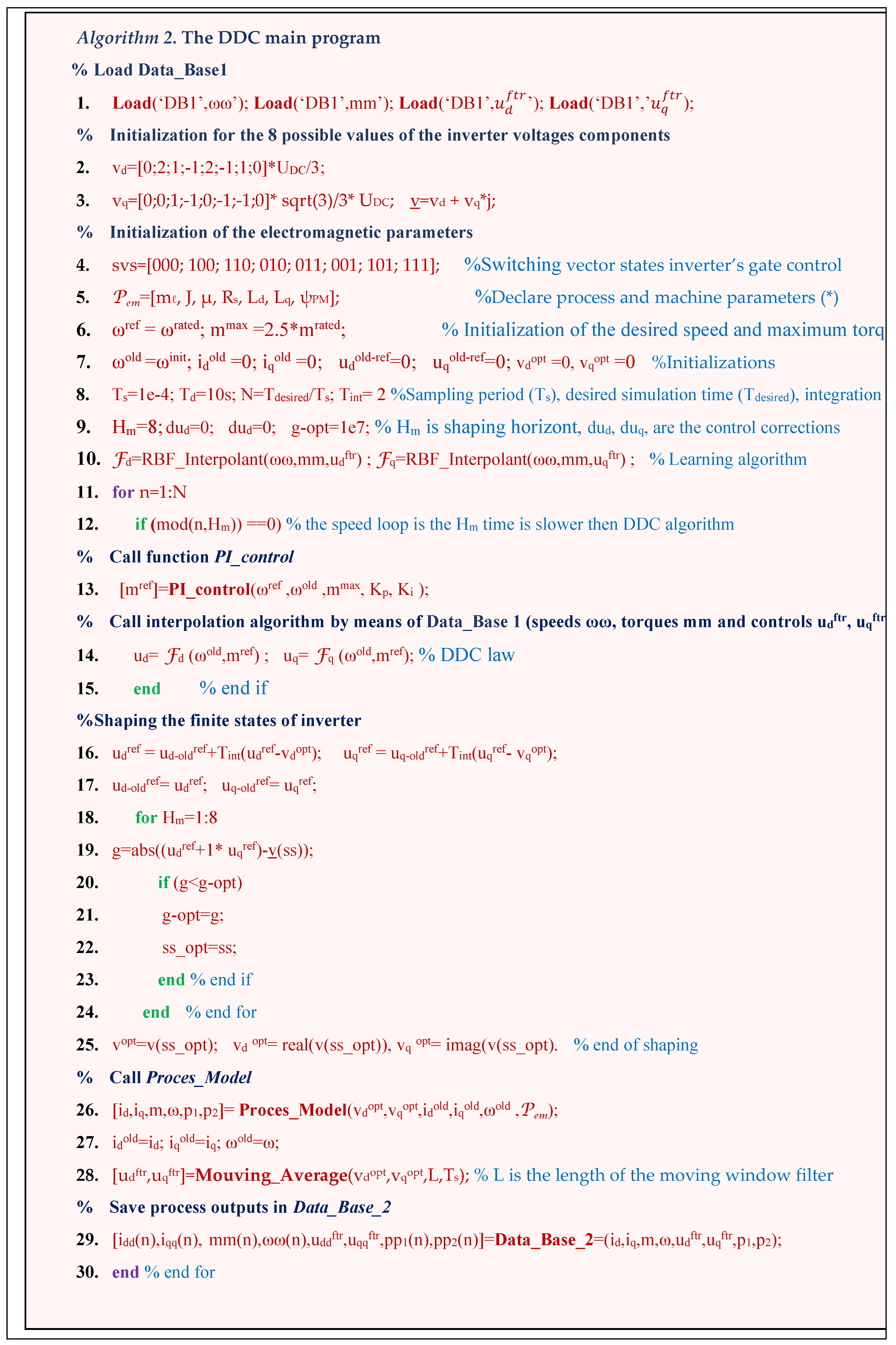
3.4.2. DDC Algorithm
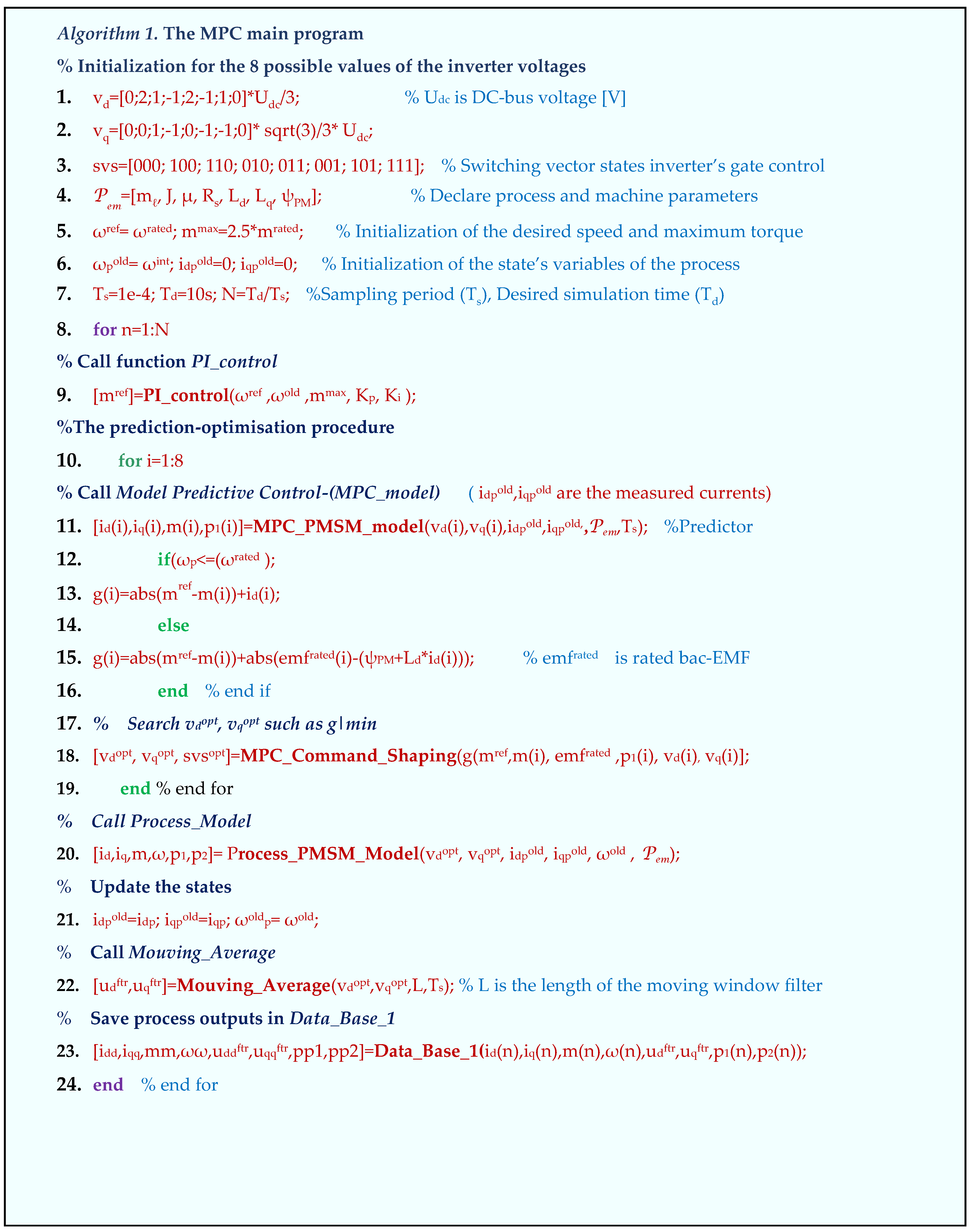
- The PI_control which calculate the actual torque set point mref using the measured past speed ωmold and the speed set point ωmref, and the tunning parameters Kp and Ki ;
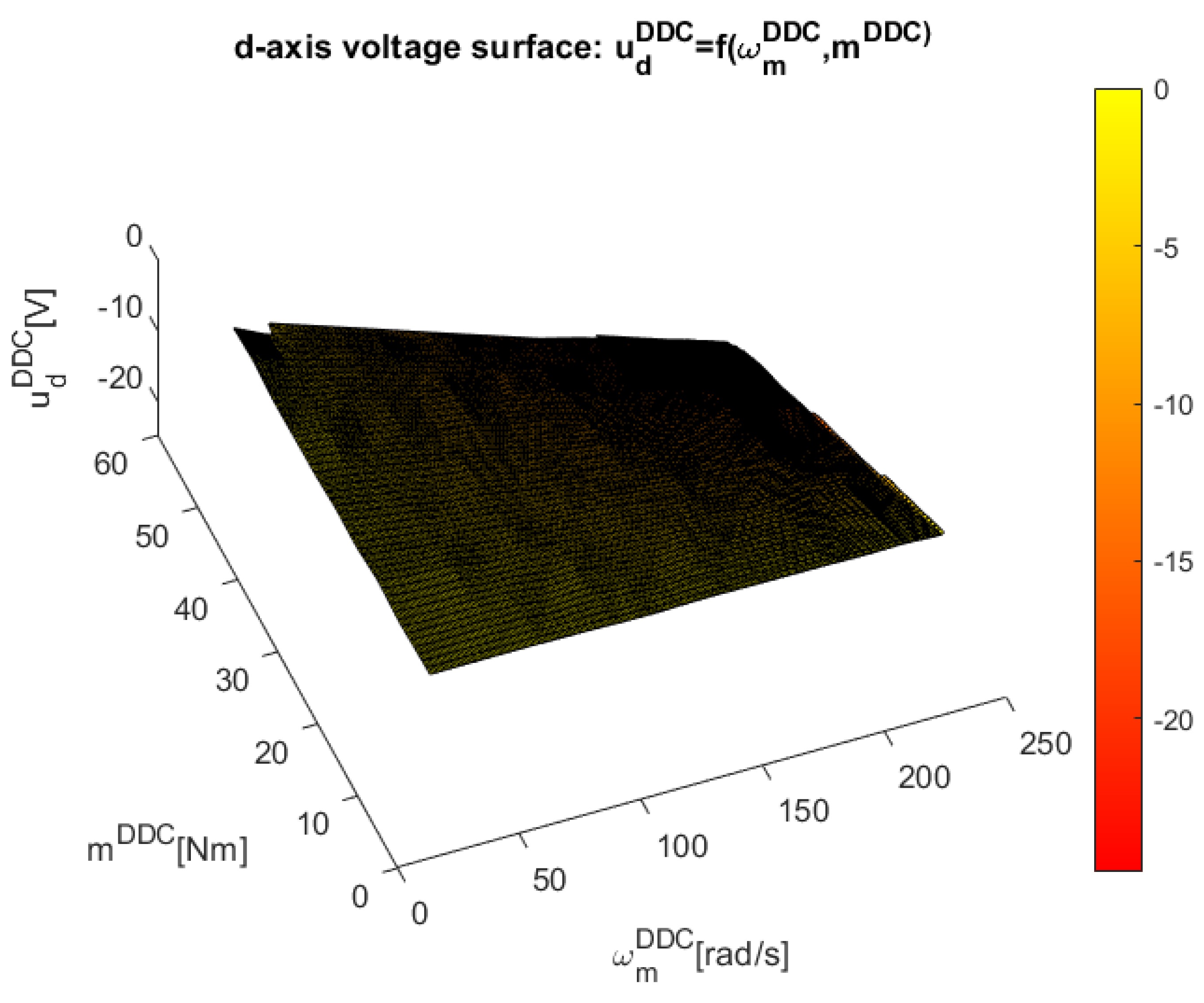
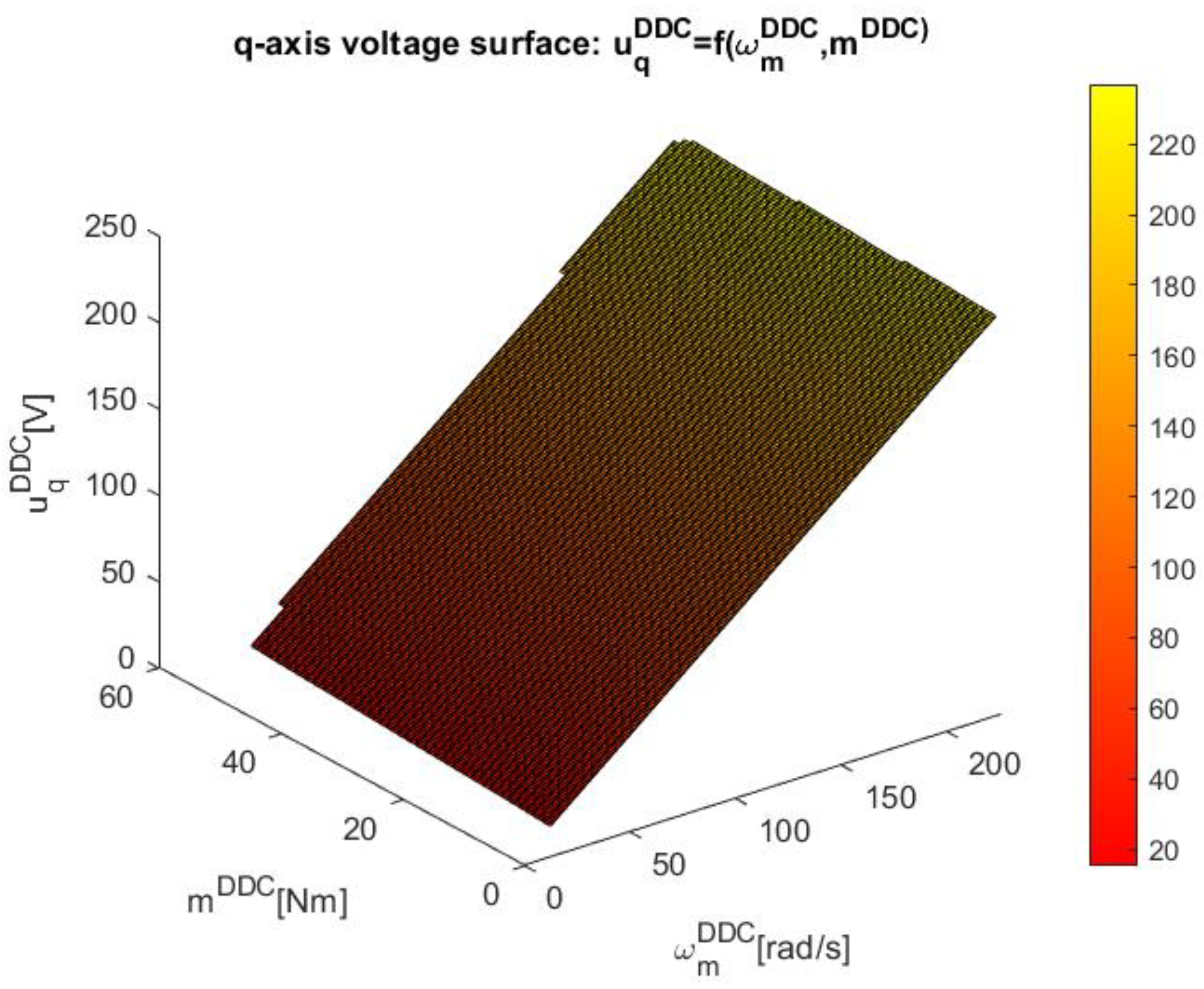
- The matlab RBF_Interpolant function which interpolate the control surfaces (24) by scattered support points contained in DB 1;
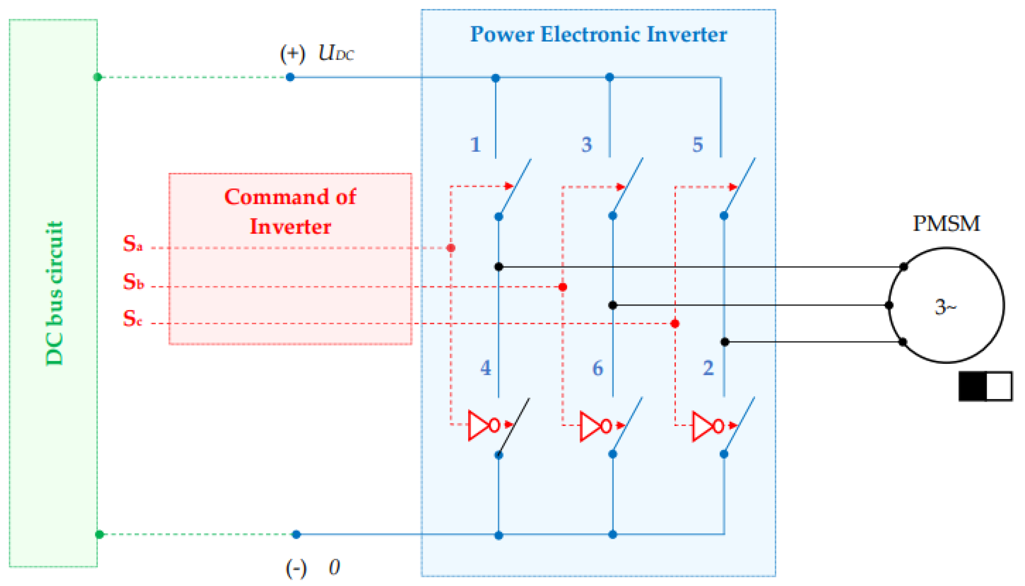
- The function Process_Model which calculate the actual process variables (id,iq,m,ω,) and the powers p1,p2.
4. Illustrative Case Study of DDC of a PMSM Drive System
4.1. Database Learning Design
4.2. Study on Rated Data Conditions
3.3. Study on Mismatch Conditions
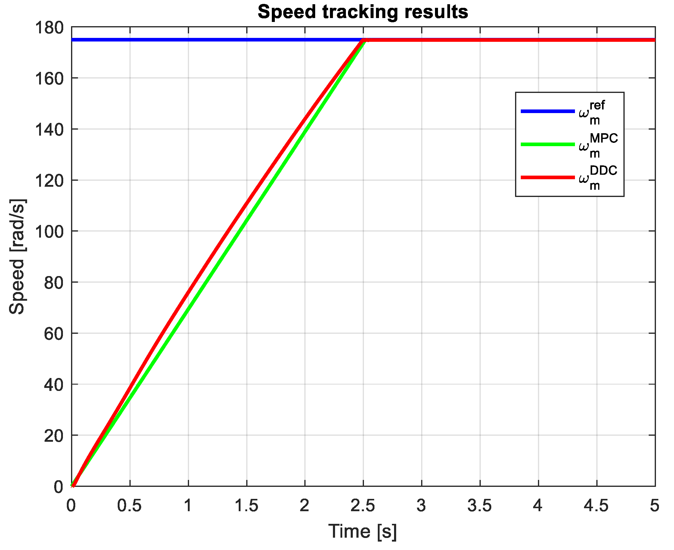
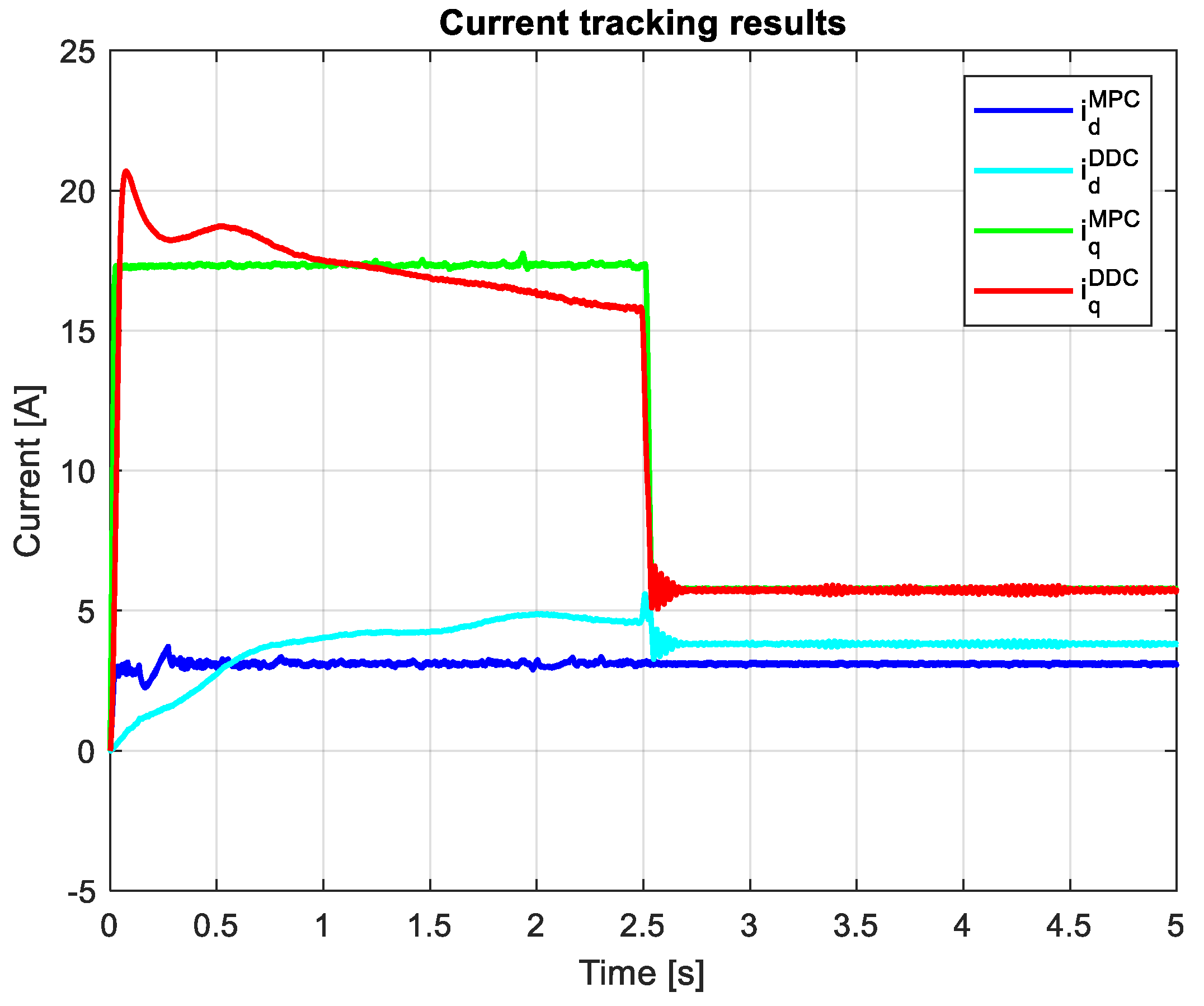
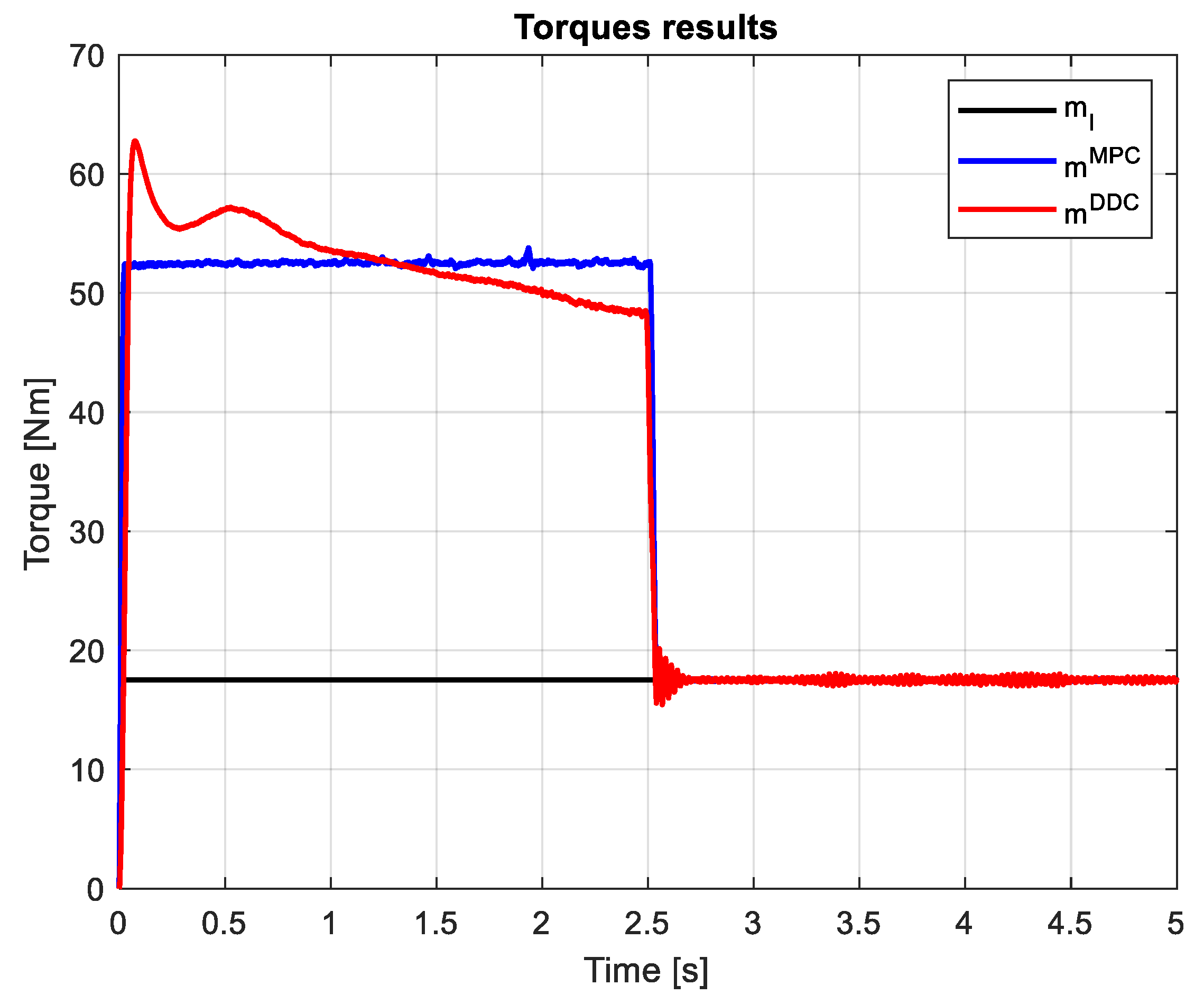
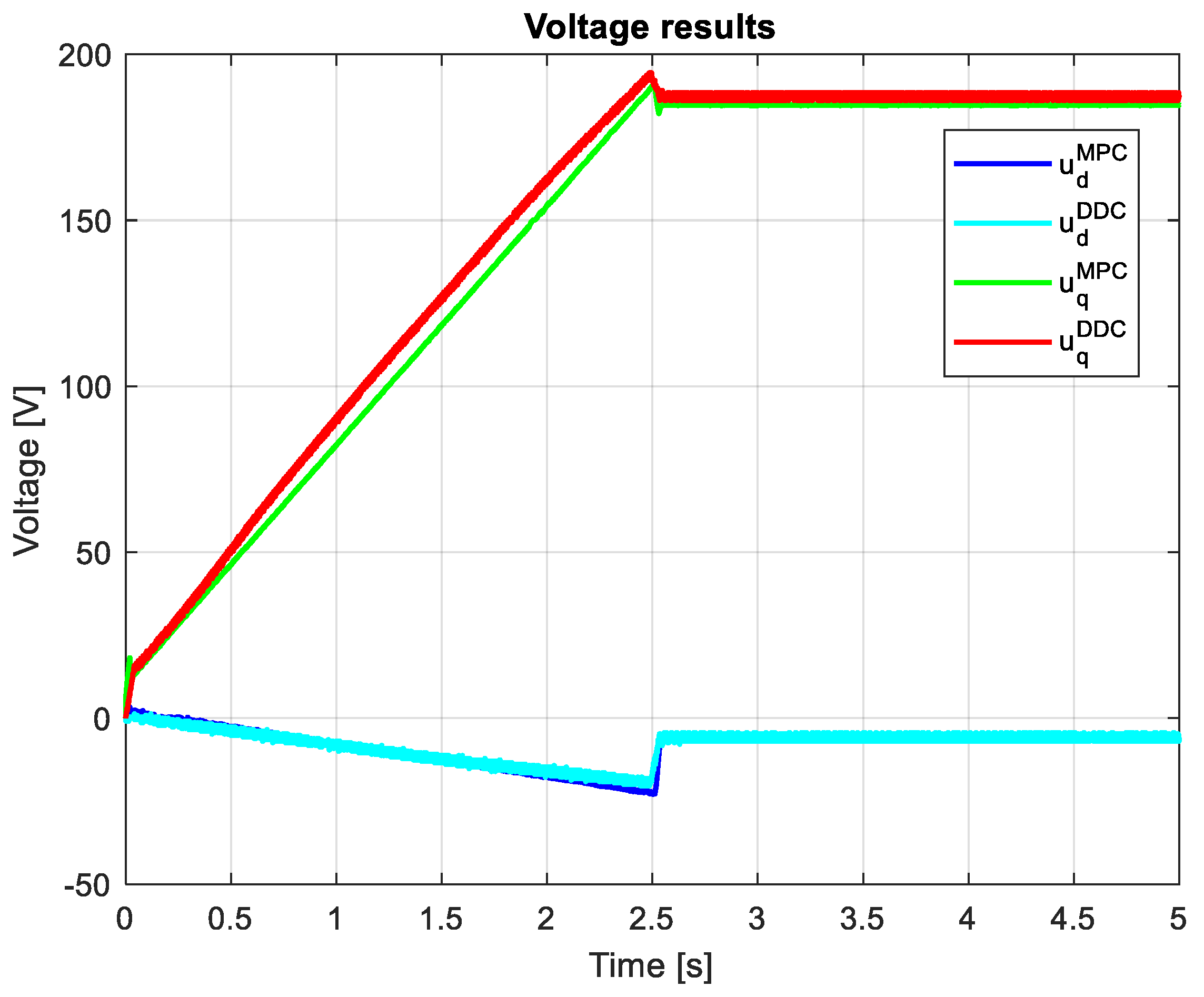
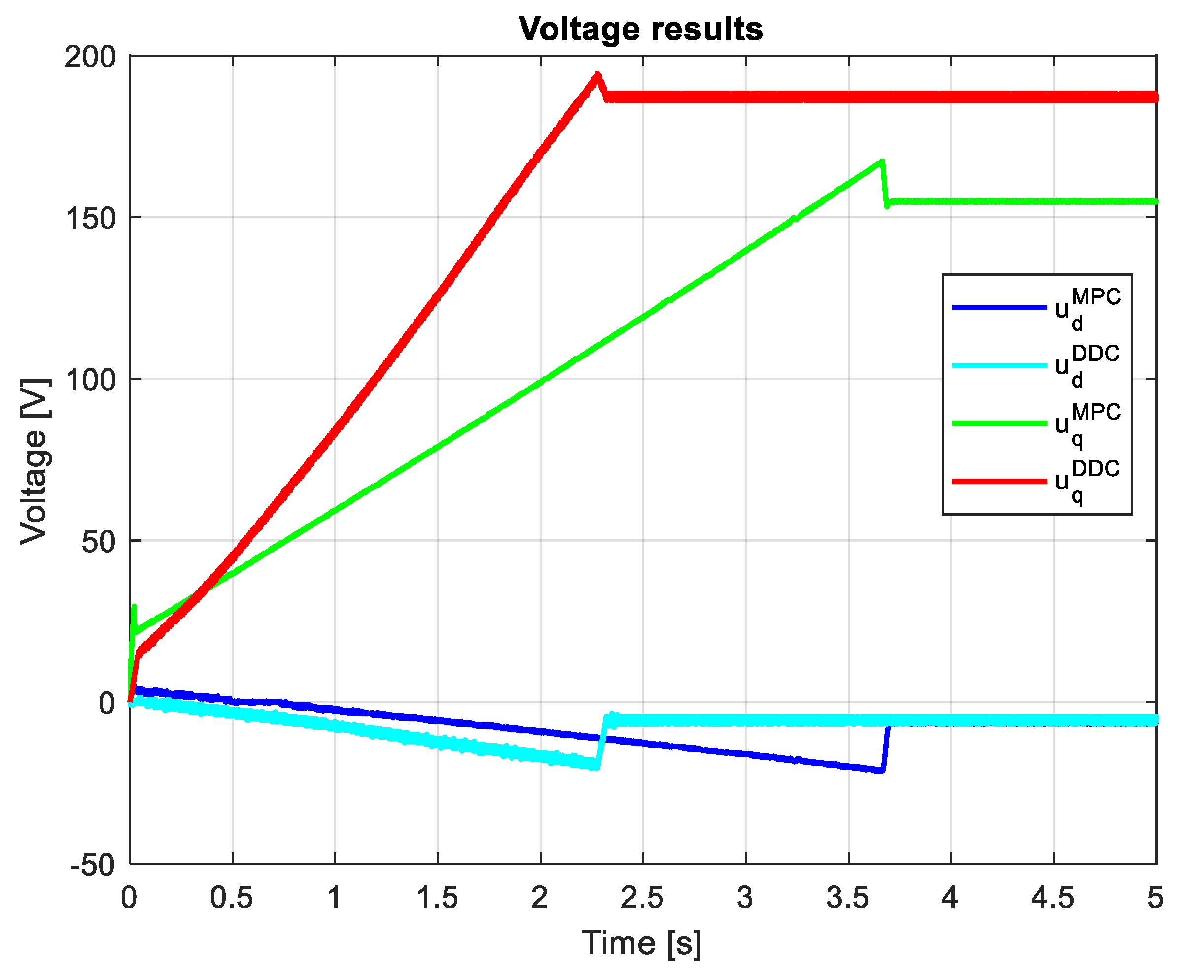
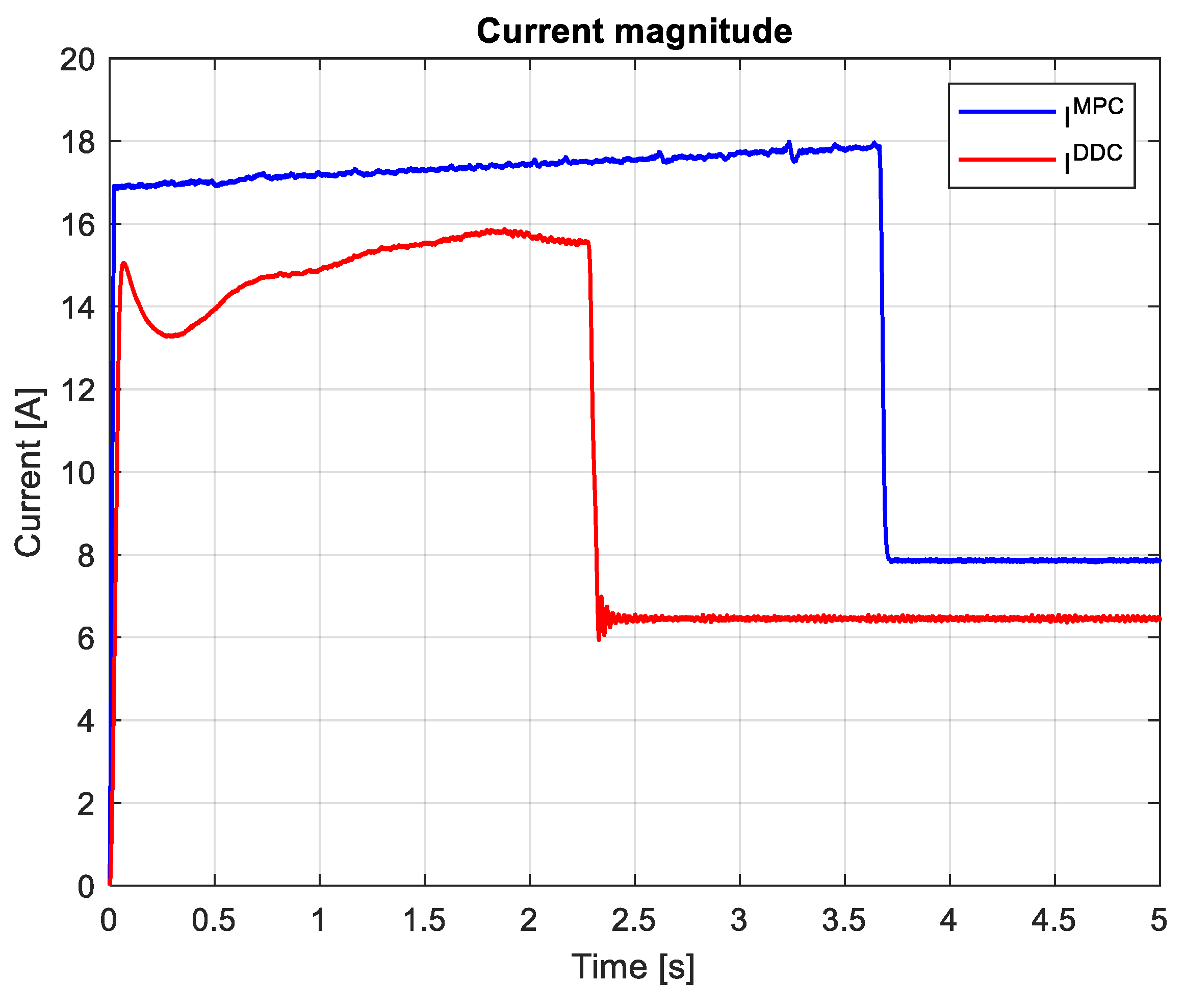
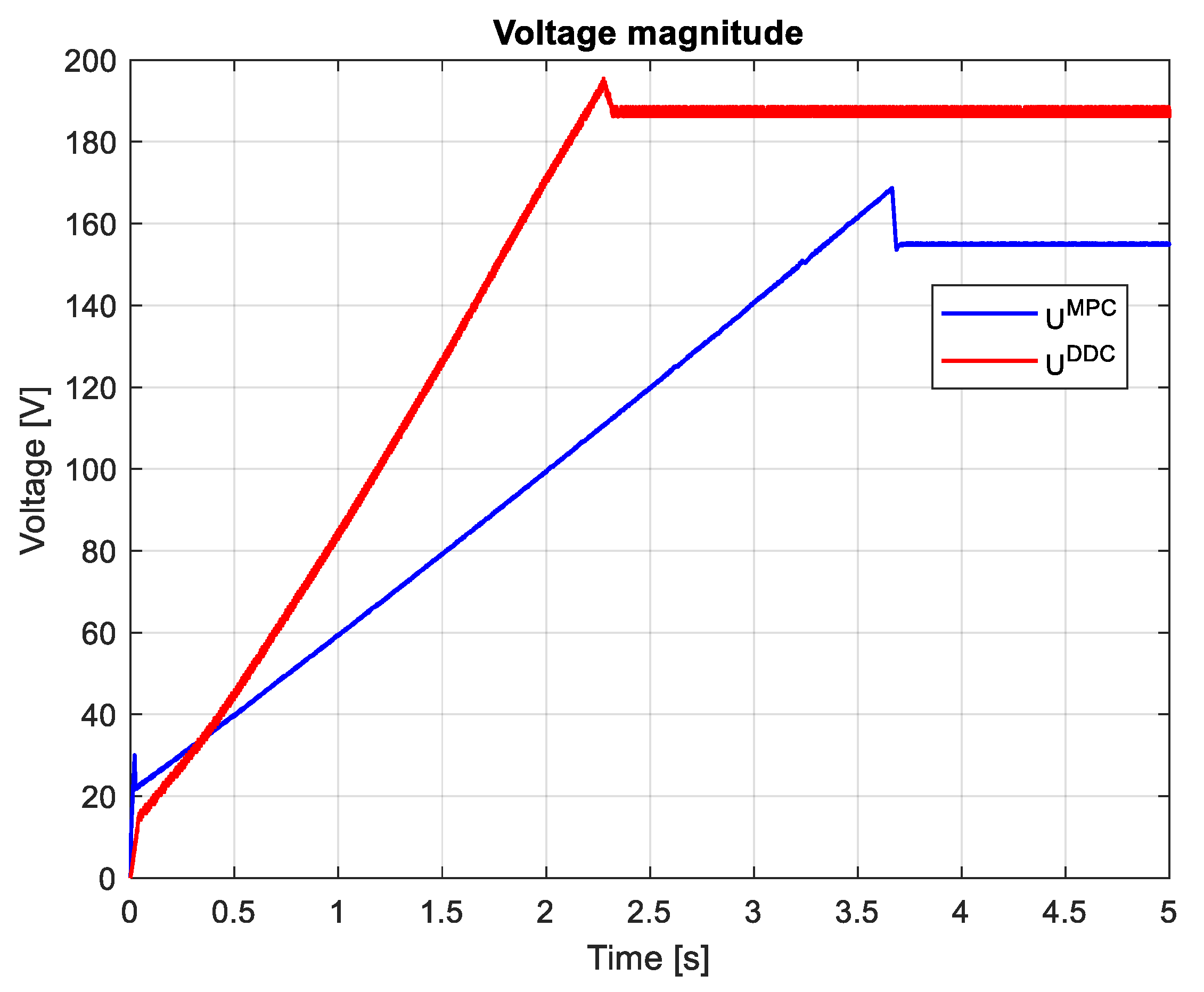
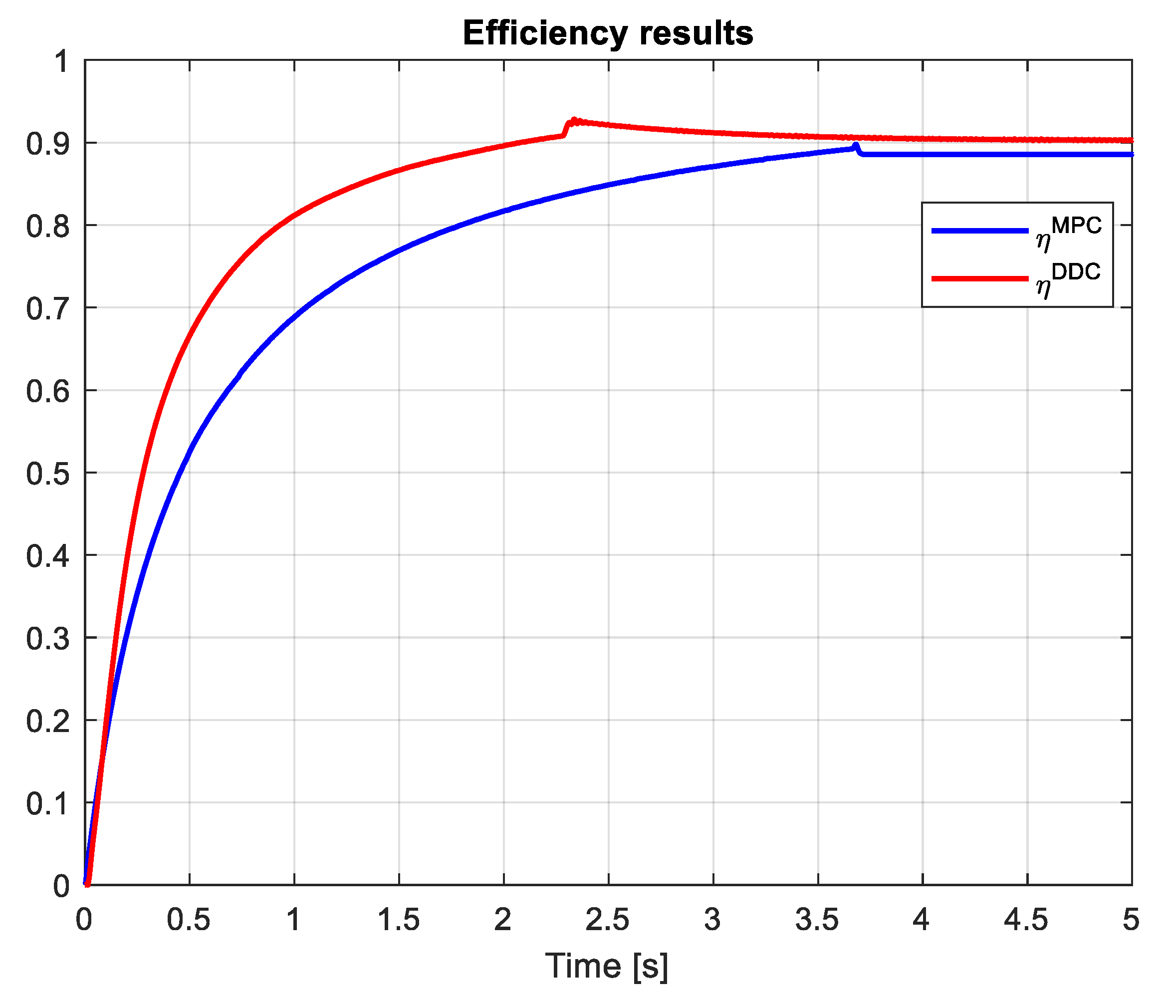
3.4. Comparative analysis of MPC and DDC results
- -
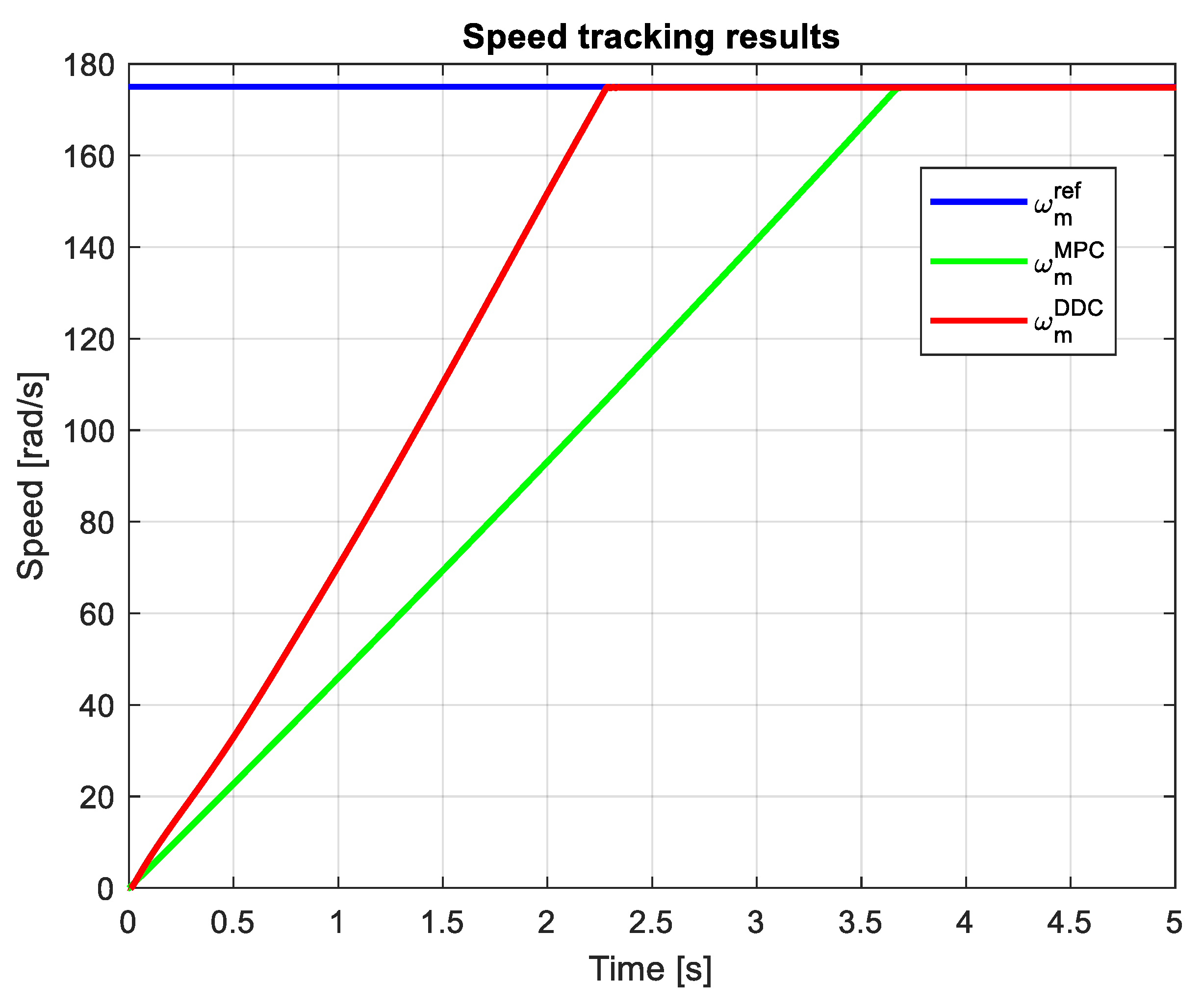
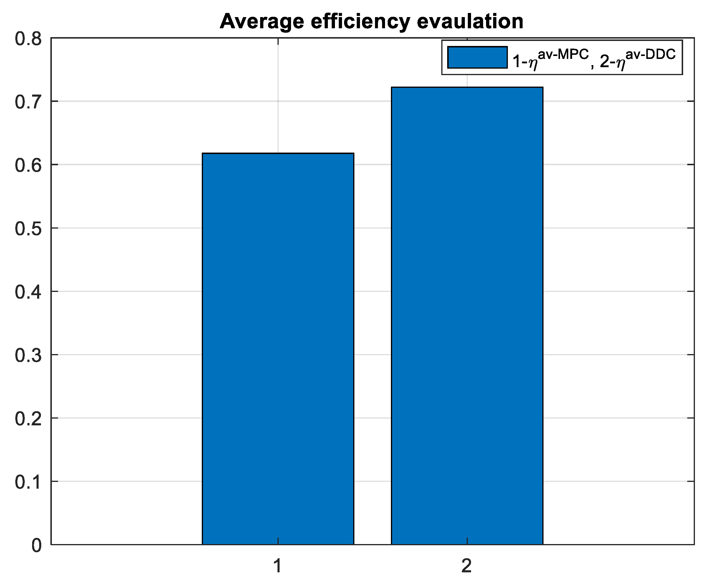
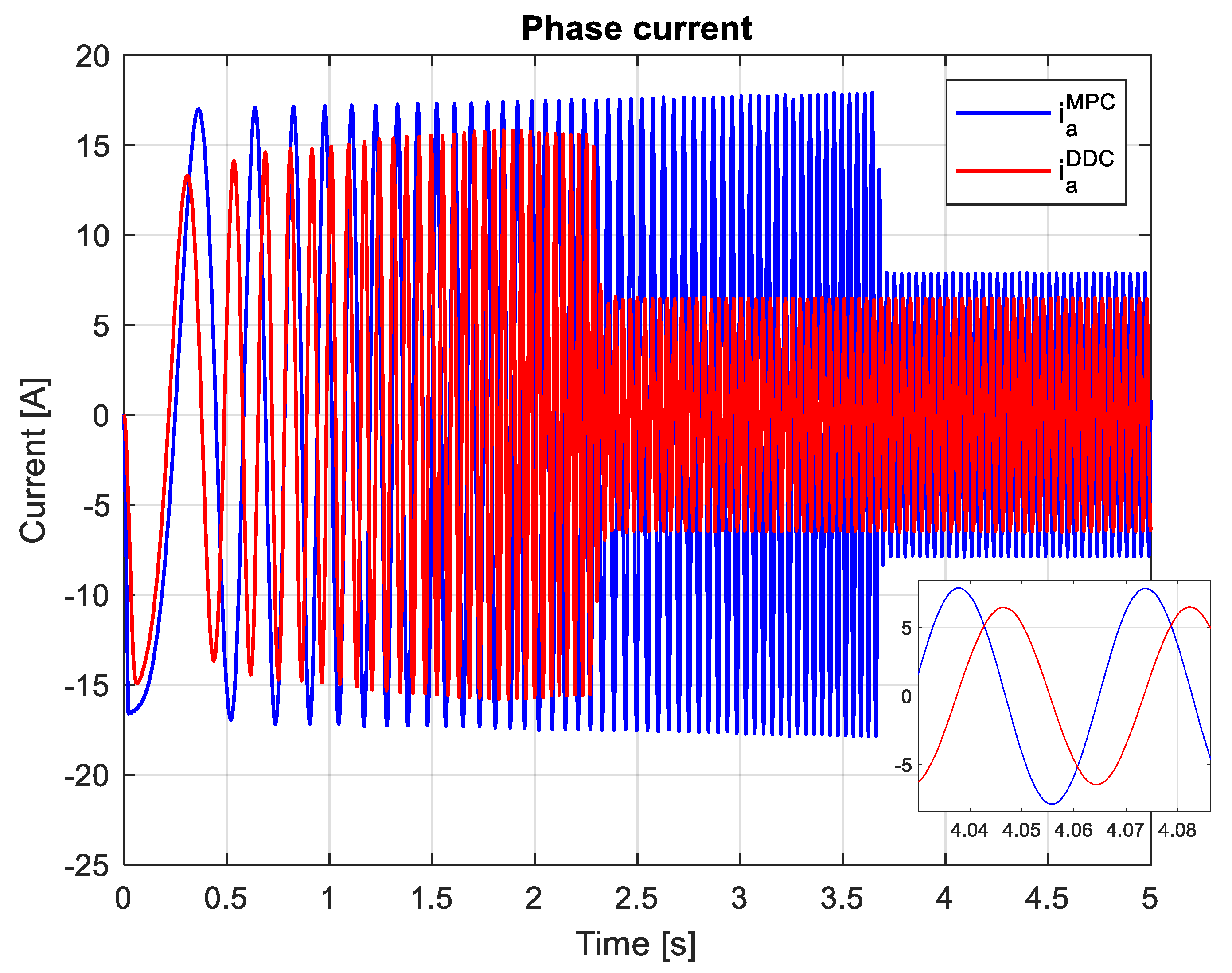
- Settling time of the mechanical speed – tst;
- -
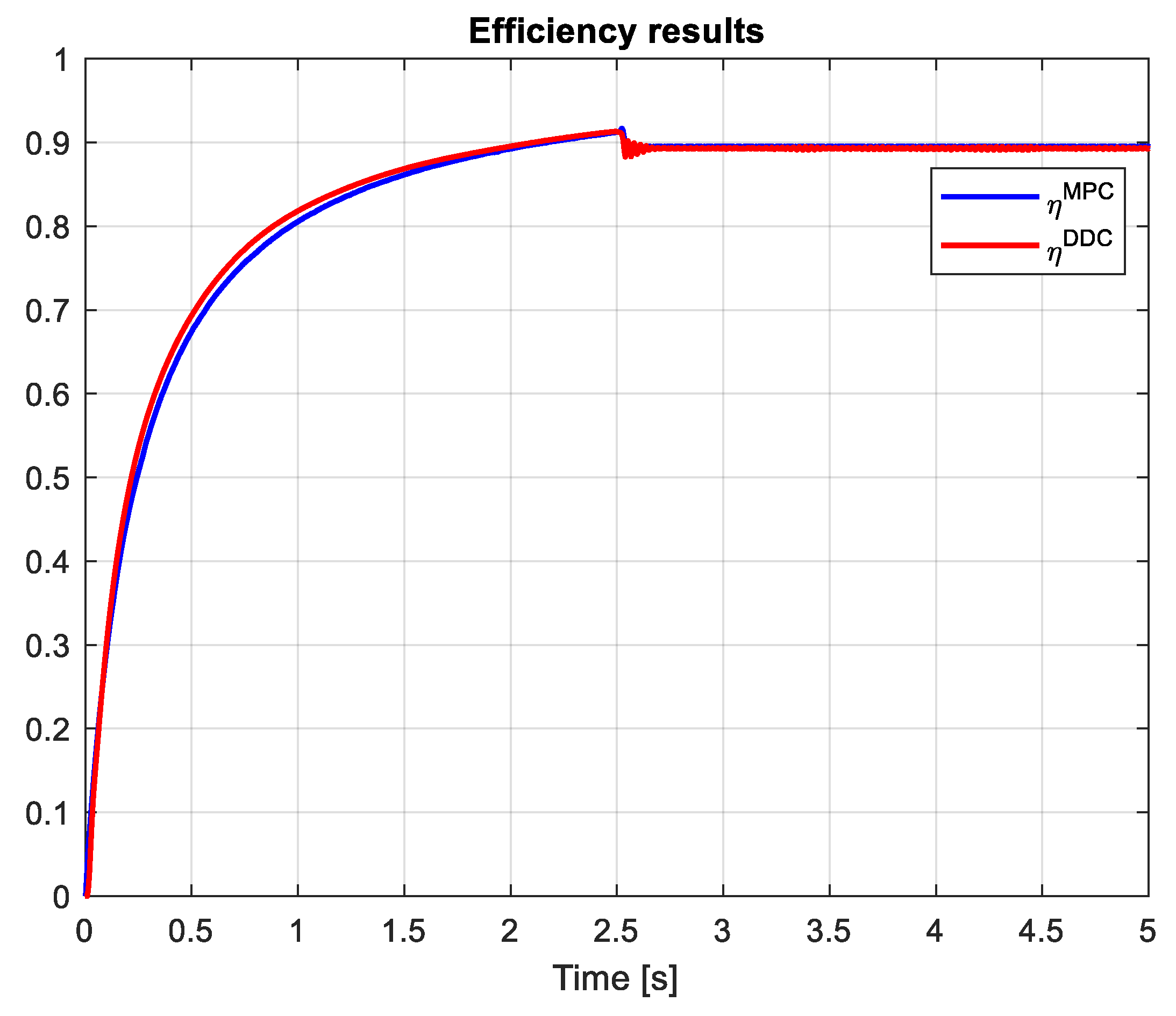
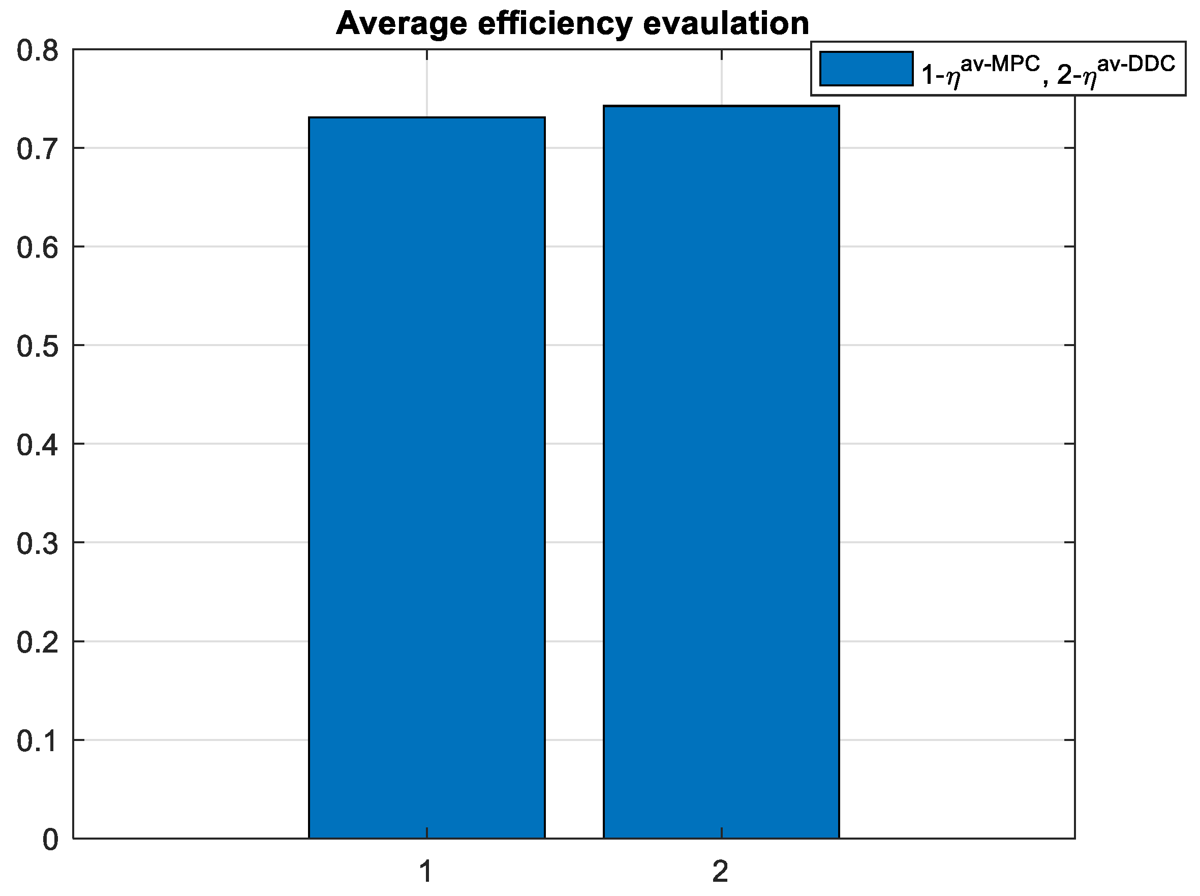
- Average efficiency on the entire simulation time– ηav;
- -
- Peak value of the a phase current in steady-state regime– Iapk;
- -
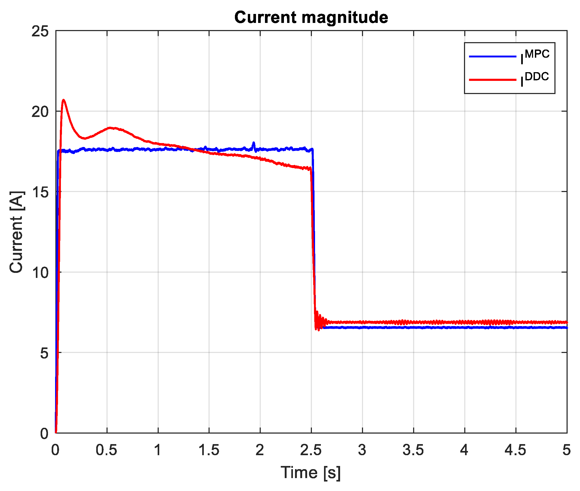
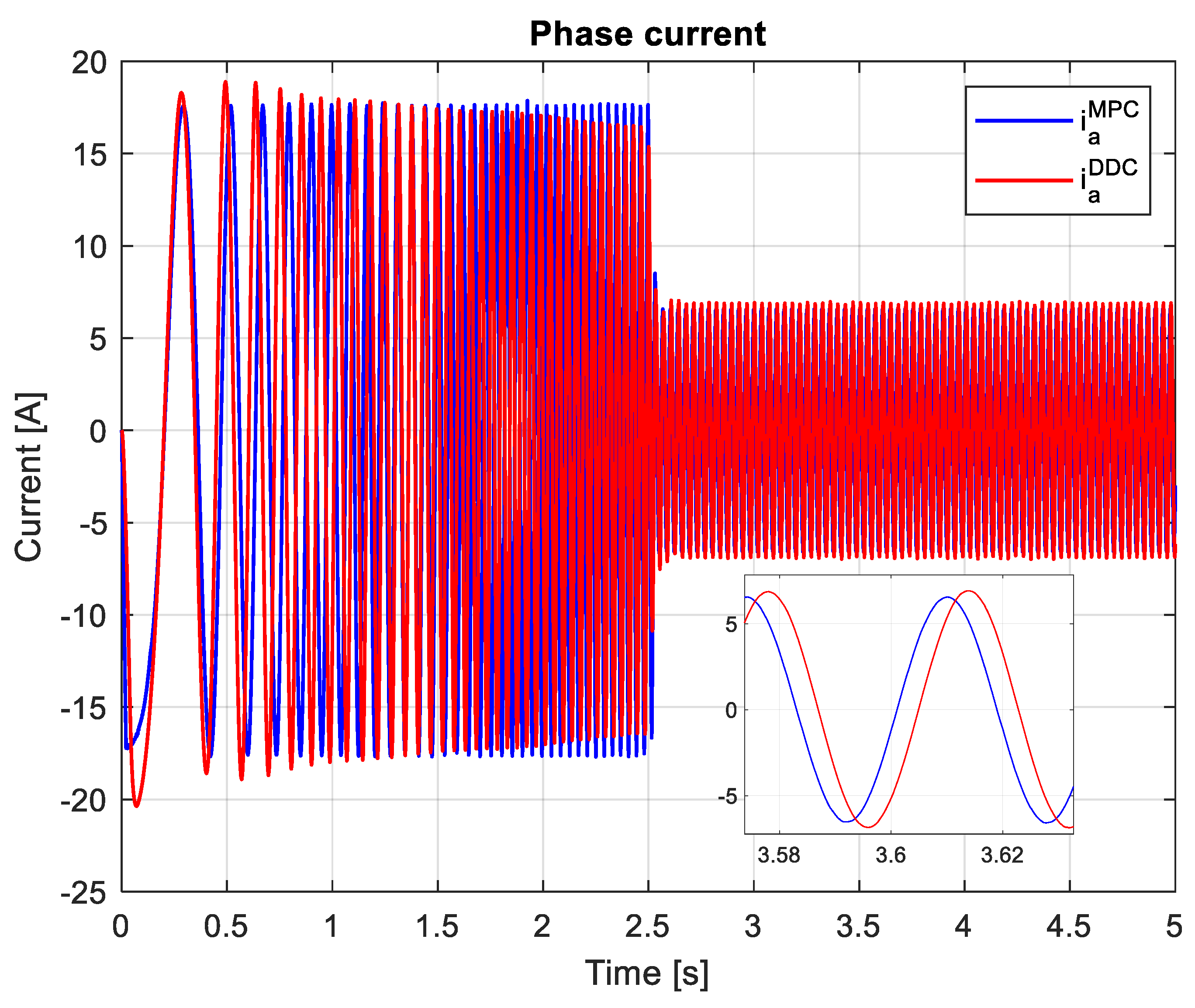
- THD of the a phase current computed in steady-state regime, for ten harmonics, including the fundamental of the frequency 55.66 Hz, for a comman time domain pf MPC and DDC strategies, 4-5 s time.
5. Conclusions

Author Contributions
Funding
Data Availability Statement
Conflicts of Interest
References
- Sul, S.K. Control of Electric Machine Drive Systems, John Wiley and Sons: Hoboken, NJ, USA, 2011.
- Vas, P. Sensorless Vector and Direct Torque Control, Oxford University Press, NY, USA, 1998.
- Rodriguez, J.; Cortes, P. Predictive Control of Power Converters and Electrical Drives, John Wiley & Sons, Ltd.: West Sussex, UK, 2012.
- Holtz, J. Advanced PWM and predictive control—An overview. IEEE Trans. Ind. Electron. 2016, 63, 3837–3844. [Google Scholar] [CrossRef]
- Casadei, D.; Serra, G.; Tani, K. Implementation of a direct control algorithm for induction motors based on discrete space vector modulation. IEEE Trans. Power Electron. 2000, 15, 769–777. [Google Scholar] [CrossRef]
- Vafaie, M.; Dehkordi, B.; Moallem, P.; Kiyoumarsi, A. Minimizing torque and flux ripples and improving dynamic response of PMSM using a voltage vector with optimal parameters. IEEE Trans. Ind. Electron. 2015, 63, 3876–3888. [Google Scholar] [CrossRef]
- Vazquez, S.; Leon, J. I.; Franquelo, L.G.; Rodriguez, J.; Young, H. A.; Marquez, A.; Zanchetta, P. Predictive control: a review of its applications in power electronics. IEEE Ind. Electron. Mag. 2014, 8, 16–31. [Google Scholar] [CrossRef]
- Vazquez, S.; Rodriguez, J.; Rivera, M.; Franquelo, L.G.; Norambuena, M. Model predictive control for power converters and drives: Advances and trends. IEEE Trans. Ind. Electron. 2017, 64, 935–947. [Google Scholar] [CrossRef]
- Rodríguez, J.; Kennel, R.M.; Espinoza, J.R.; Trincado, M.; Silva, C.A.; Rojas, C.A. High-performance control strategies for electrical drives: An experimental assessment. IEEE Trans. Ind. Electron. 2011, 59, 812–820. [Google Scholar] [CrossRef]
- Zhang, K.; Fan, M.; Yang, Y.; Zhu, Z.; Garcia, C.; Rodriguez, J. Field enhancing model predictive direct torque control of permanent magnet synchronous machine. IEEE Trans. Energy Convers. 2021, 36, 2924–2933. [Google Scholar] [CrossRef]
- Schwenzer, M.; Ay, M.; Bergs, T.; Abel, D. Review on model predictive control: an engineering perspective. Int J Adv Manuf Technol. 2021, 117, 1327–1349. [Google Scholar] [CrossRef]
- Richter, J.; Doppelbauer, M. Predictive trajectory control of permanent-magnet synchronous machines with nonlinear magnetic. IEEE Trans. Ind. Electron. 2016, 63, 3915–3924. [Google Scholar] [CrossRef]
- Djerioui, A.; Houari, A.; Machmoum, M.; Ghanes, M. Grey wolf optimizer-based predictive torque control for electric buses applications. Energies 2020, 13, 5013. [Google Scholar] [CrossRef]
- Siami, M.; Khaburi, D.A.; Abbaszadeh, A.; Rodriguez, J. Robustness improvement of predictive current control using prediction error correction for permanent-magnet synchronous machines. IEEE Trans. Ind. Electron. 2016, 63, 3458–3466. [Google Scholar] [CrossRef]
- Hu, F.; Luo, D.; Luo, C.; Long, Z.; Wu, G. Cascaded robust fault-tolerant predictive control for PMSM drives. Energies 2018, 11, 3087. [Google Scholar] [CrossRef]
- Singh, B.; Jain, P.; Mittal, A.P.; Gupta, J.R.P. Torque ripples minimization of DTC IPMSM drive for the EV propulsion system using a neural network. J. Power Electron. 2008, 8, 23–34. [Google Scholar]
- Wang, W.; Liu, Y.; Chen, H.; Gao, J.; Zhu, S.; Zhou, R. Improved Rotor Flux-Based SMO and RBF-PID Control Strategy for PMSM. Actuators 2023, 12, 327. [Google Scholar] [CrossRef]
- Qian, W.; Panda, S.K.; Xu, J.X. Torque ripple minimization in PM synchronous motors using iterative learning control. IEEE Trans. Power Electron. 2004, 19, 272–279. [Google Scholar] [CrossRef]
- Wang, G.; Xie, J.; Wang, S. Application of Artificial Intelligence in Power System Monitoring and Fault Diagnosis. Energies 2023, 16, 5477. [Google Scholar] [CrossRef]
- Schenke, M.; Kirchgassner, W.; Wallscheid, O. Controller design for electrical drives by deep reinforcement learning: A proof of concept. IEEE Trans. Ind. Informat. 2020, 16, 4650–4658. [Google Scholar] [CrossRef]
- Xie, H.; Wang, F.; Xun, Q.; He, Y.; Rodriguez, J.; Kennel, R. A low-complexity gradient descent solution with backtracking iteration approach for finite control set predictive current control. IEEE Trans. Ind. Electron. 2020, 69, 4522–4533. [Google Scholar] [CrossRef]
- Prag, K.; Woolway, M.; Celik, T. Toward data-driven optimal control: a systematic review of the landscape. IEEE Access 2022, 10, 32190–32212. [Google Scholar] [CrossRef]
- Hou, Z. S.; Wang, Z. From model-based control to data-driven control: survey, classification and perspective. Inf. Sci. 2013, 235, 3–35. [Google Scholar] [CrossRef]
- Markovsky, I.; Dörfler, F. Behavioral systems theory in data-driven analysis, signal processing, and control. Annu. Rev. Control 2021, 52, 42–64. [Google Scholar] [CrossRef]
- Markovsky, I.; Dörfler, F. Data-driven dynamic interpolation and approximation. Automatica 2022, 135, 110008. [Google Scholar] [CrossRef]
- Hao, W. Data-Driven Control with Learned Dynamics. Ph.D. Dissertation, Clemson University, South Carolina, USA, August 2020. [Google Scholar]
- Dörfler, F.; Coulson, J.; Markovsky, I. Bridging direct and indirect data-driven control formulations via regularizations and relaxations. IEEE Trans. Autom. Control 2023, 68, 2023. [Google Scholar] [CrossRef]
- De Persis, C.; Tesi, P. Formulas for data-driven control: stabilization, optimality, and robustness. IEEE Trans. Autom. Control 2020, 65, 909–924. [Google Scholar] [CrossRef]
- Kadali, R.; Huang, B.; Rossiter, A. A data driven subspace approach to predictive controller design. Control Eng. Pract. 2003, 11, 261–278. [Google Scholar] [CrossRef]
- Coulson, J.; Lygeros, J.; Dorfler, F. Distributionally robust chance constrained data-enabled predictive control. IEEE Trans. Autom. Control 2021, 67, 3289–3304. [Google Scholar] [CrossRef]
- Abolpour, R.; Khayatian, A.; Dehghani, M. Simultaneous model prediction and data-driven control with relaxed assumption on the model. ISA Transactions 2024, 145, 225–238. [Google Scholar] [CrossRef]
- Yang, L.; Ma, A.; Li, D.; Xi, Y. Input-mapping based data-driven model predictive control for unknown linear systems with bounded disturbances. Automatica 2023, 153, 111056. [Google Scholar] [CrossRef]
- Yang, L.; Li, D.; Ma, A.; Xi, Y.; Pu, Y.; Tan, Y. Input-mapping based data-driven model predictive control for unknown linear systems via online learning. International Journal of Robust and Nonlinear Control 2022. [Google Scholar] [CrossRef]
- Coulson, J.; Lygeros, J.; Dorfler, F. Data-Enabled Predictive Control: In the Shallows of the DeePC. In Proceedings of the 18th European Control Conference (ECC), Naples, Italy, 25-28 June 2019; pp. 307–312. [Google Scholar]
- Brosch, A.; Hanke, S.; Wallscheid, O.; Bocker, J. Data-driven recursive least squares estimation for model predictive current control of permanent magnet synchronous motors. IEEE Trans. Power Electron. 2021, 36, 2179–2190. [Google Scholar] [CrossRef]
- Carlet, P. G.; Favato, A.; Bolognani, S.; Dörfler, F. Data-driven continuous-set predictive current control for synchronous motor drives. IEEE Trans. Power Electron. 2022, 37, 6637–6646. [Google Scholar] [CrossRef]
- Carlet, P. G.; Favato, A.; Torchio, R.; Toso, F.; Bolognani, S.; Dörfler, F. Real-time feasibility of data-driven predictive control for synchronous motor drives. IEEE Trans. Power Electron. 2023, 38, 1672–1682. [Google Scholar] [CrossRef]
- Xie, Y.; Tang, X.; Song, B.; Zhou, X.; Guo, Y. Data-driven adaptive fractional order PI control for PMSM servo system with measurement noise and data dropouts. ISA Transactions 2018, 75, 172–188. [Google Scholar] [CrossRef] [PubMed]
- Guo, Q.; Zhang, C.; Li, L.; Zhang, J.; Wang, M. Maximum Efficiency per Torque Control of Permanent-Magnet Synchronous Machines. Appl. Sci. 2016, 6, 425. [Google Scholar] [CrossRef]
- Cavallaro, C.; Tommaso, A.O.; Miceli, R.; Raciti, A.; Galluzzo, G.R.; Trapanese, M. Efficiency Enhancement of Permanent-Magnet Synchronous Motor Drives by Online Loss Minimization Approaches. IEEE Trans. Ind. Electron. 2005, 52, 1153–1160. [Google Scholar] [CrossRef]
- Ni, R.G.; Xu, D.G.; Wang, G.L.; Ding, L.; Zhang, G.Q.; Qu, L.Z. Maximum Efficiency Per Ampere Control of Permanent-Magnet Synchronous Machines. IEEE Trans. Ind. Electron. 2015, 62, 2135–2143. [Google Scholar] [CrossRef]
- McCarthy, J.; Minsky, M.L.; Rochester, N.; Shannon, C.E. A Proposal for the Dartmouth Summer Research Project on Artificial Intelligence, August 31, 1955. AI Magazine. 27, 4 (Dec. 2006), 12.
- Liu, J. Radial Basis Function (RBF) neural network control for mechanical systems: design, analysis and Matlab simulation. Springer Science & Business Media, 2013.
- Kaminski, M. Nature-Inspired Algorithm Implemented for Stable Radial Basis Function Neural Controller of Electric Drive with Induction Motor. Energies 2020, 13, 6541. [Google Scholar] [CrossRef]
- Astrom, K.J.; Wittenmark, B. Computer-Controlled Systems: Theory and Design, 3rd ed. Prentice Hall: Upper Saddle River, NJ, USA, 1997.

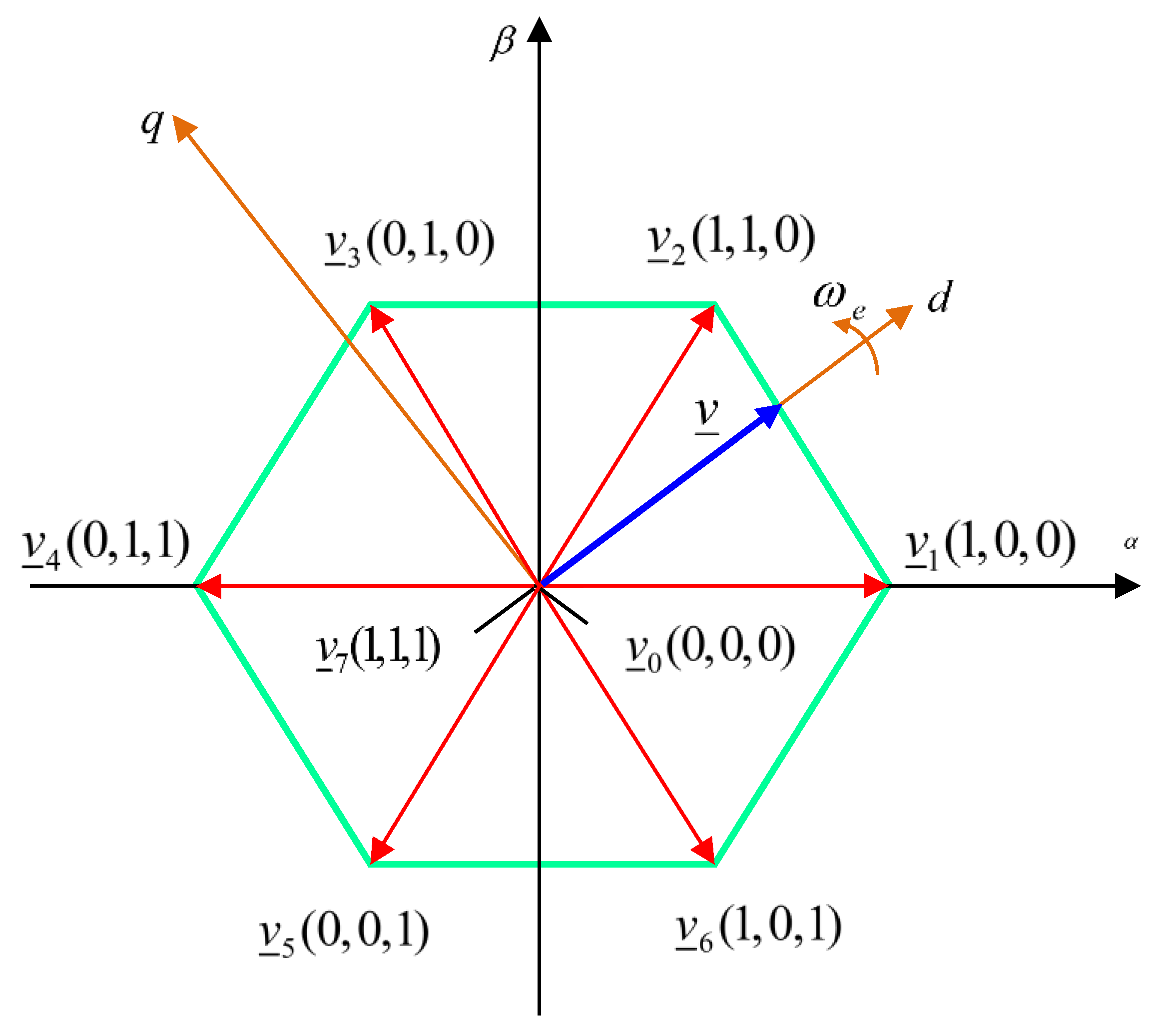

| Index i | Sabc | Voltage space vector |
|---|---|---|
| 1 | ||
| 2 | ||
| 3 | ||
| 4 | ||
| 5 | ||
| 6 | ||
| 7 | ||
| 8 |
| Symbol | Description | Values |
|---|---|---|
| PN [W] | Rated power | 5500 |
| UN [V] | Rated voltage | 325 |
| mN [Nm] | Rated torque | 35 |
| IN [A] | Rated current | 10.6 |
| ωmN [rad/sec] | Rated speed | 157 |
| Rs [Ω] | Rotor resistence | 0.65 |
| Ld [H] | Direct axis inductance | 0.0082 |
| Lq [H] | Quadrature axis inductance | 0.0082 |
| J[kg∙m2] | Total inertia of the PMSM drive | 0.5 |
| zp | Stator pole pairs | 2 |
 |
Disclaimer/Publisher’s Note: The statements, opinions and data contained in all publications are solely those of the individual author(s) and contributor(s) and not of MDPI and/or the editor(s). MDPI and/or the editor(s) disclaim responsibility for any injury to people or property resulting from any ideas, methods, instructions or products referred to in the content. |
© 2024 by the authors. Licensee MDPI, Basel, Switzerland. This article is an open access article distributed under the terms and conditions of the Creative Commons Attribution (CC BY) license (http://creativecommons.org/licenses/by/4.0/).


