Submitted:
08 October 2024
Posted:
09 October 2024
You are already at the latest version
Abstract
Keywords:
1. Introduction
2. Related Works
- 1)
- Network coverage: A primary goal of most routing algorithms is to ensure high and efficient network coverage to deliver essential and useful information to as many network nodes as possible.
- 2)
- Network latency: The impact of utilizing fog and edge data processing methodologies within the network is described by calculating the average network latency. The average message delivery latency in the network is calculated by summing the latencies for each unique message across all nodes where it was first received.
- 3)
- Processing ratio: The ratio of data processing at the edge, fog, and cloud layers – a metric describing the effectiveness and interrelation between these layers within the FOGO architecture, which heavily depends on the number of fog nodes. The "edge/fog/cloud" processing ratio is calculated as the ratio of the total number of messages processed in a layer to the total number of messages generated during the simulation.
- 4)
- Processing efficiency: Data processing efficiency is calculated for each network architectural layer: edge, fog, and cloud. It is calculated as the ratio of the average processing time at a lower-level node to the average data transmission and processing time at a higher-level node.
3. Materials and Methods
3.1. Mathematical Model
3.2. Simulation System
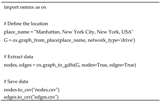
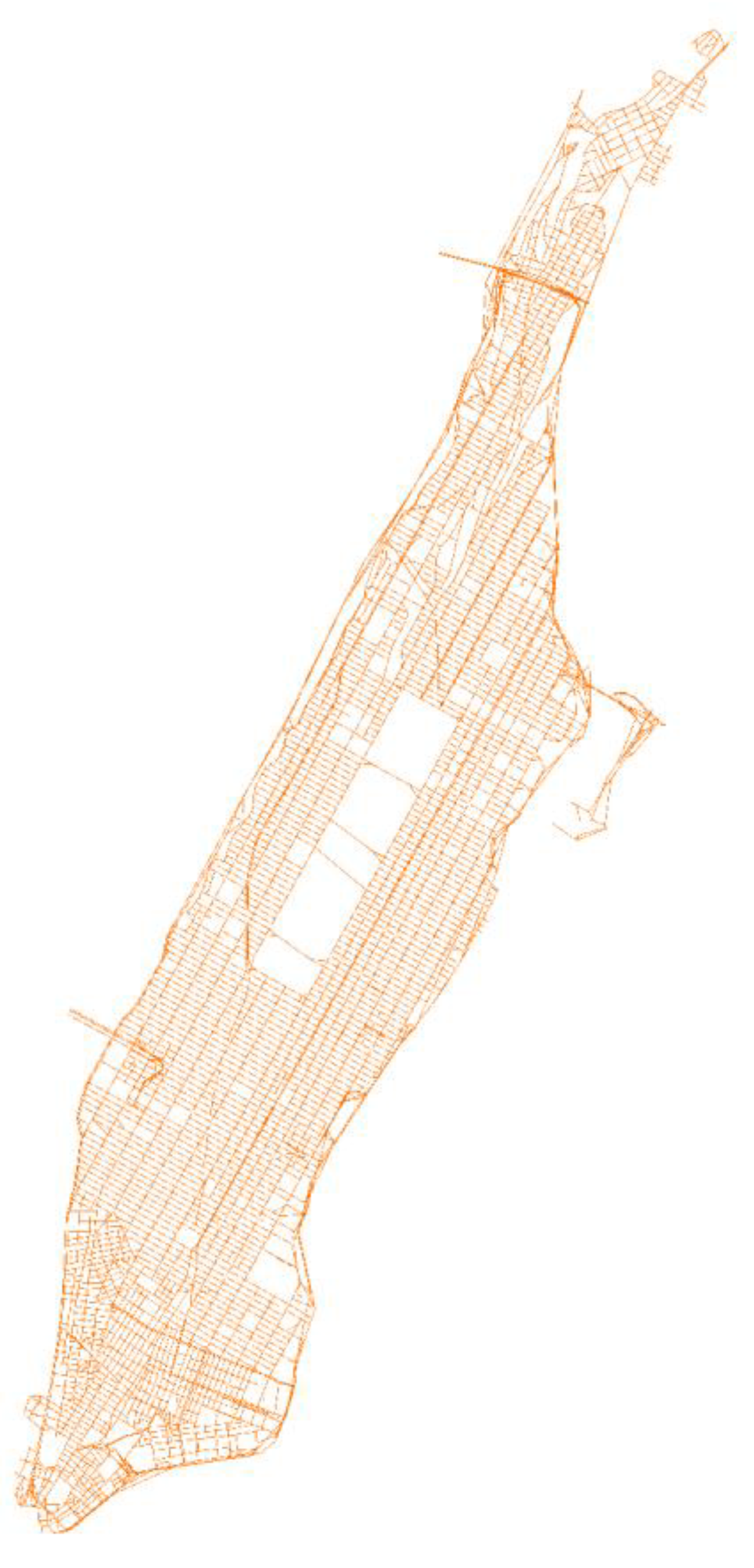
- nodes.csv: osmid, y, x, highway, street_count, ref, geometry
- edges.csv: u, v, key, osmid, name, highway, maxspeed, oneway, reversed, length, geometry, lanes, ref, access, bridge, tunnel, width, junction
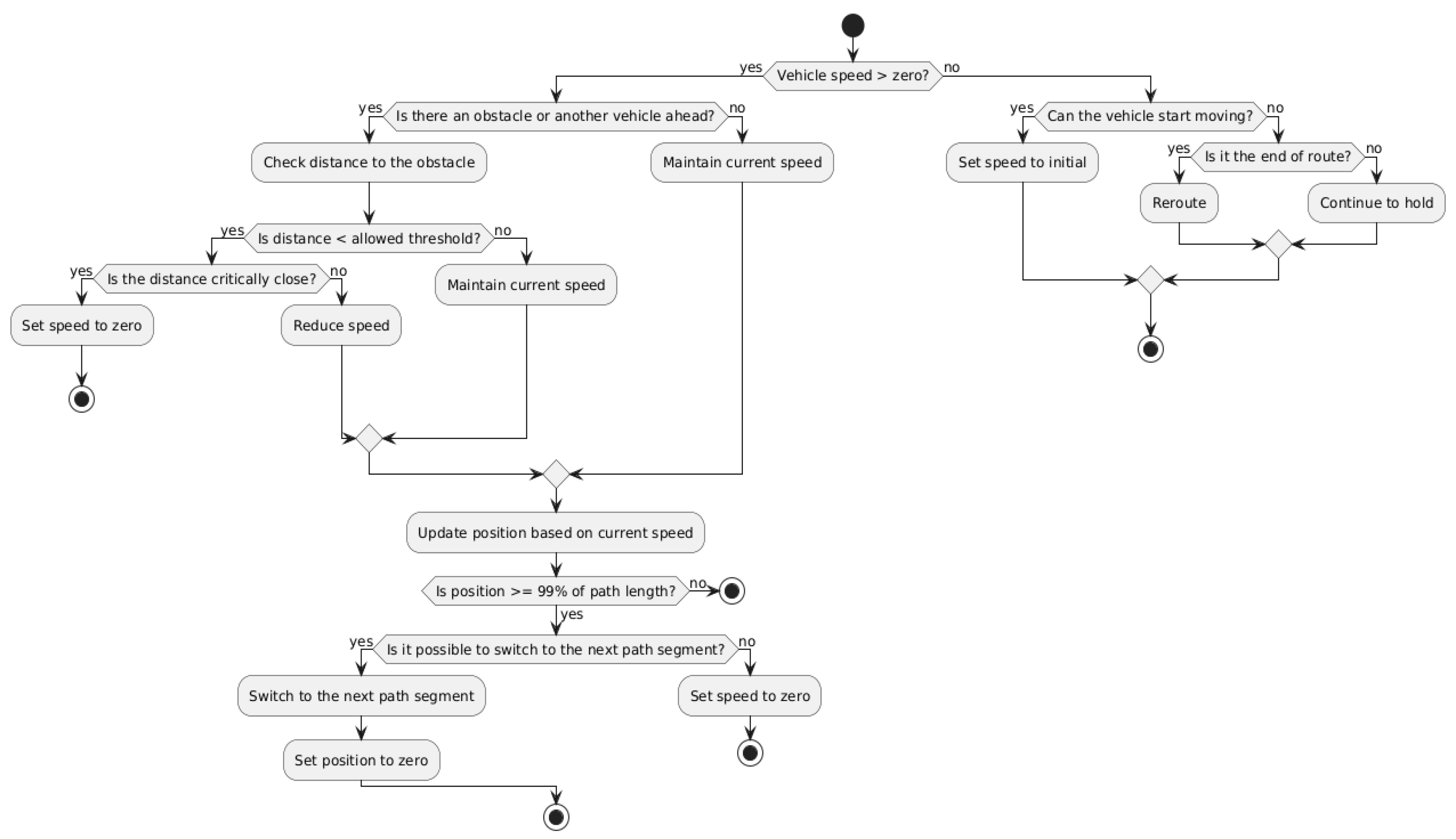
3.3. Description of the Simulation Environment and Experimental Scenarios
4. Results

5. Discussion
Author Contributions
Funding
Data Availability Statement
Conflicts of Interest
References
- Mueck, M.; Karls, I. Networking Vehicles to Everything: Evolving Automotive Solutions. Walter de Gruyter, 2018. 233 p.
- Abdelkader, G.; Elgazzar, K.; Khamis, A. Connected vehicles: Technology review, state of the art, challenges and opportunities. Sensors 2021, 21, 7712. [Google Scholar] [CrossRef] [PubMed]
- Wang, J.; Shao, Y.; Ge, Y.; Yu, R. A survey of vehicle to everything (V2X) testing. Sensors 2019, 19, 334. [Google Scholar] [CrossRef]
- Bali, R.S.; Kumar, N.; Rodrigues, J.J. Clustering in vehicular ad hoc networks: taxonomy, challenges and solutions. Vehicular Communications 2014, 1, 134–152. [Google Scholar] [CrossRef]
- Cooper, C.; Franklin, D.; Ros, M.; Safaei, F.; Abolhasan, M. A Comparative Survey of VANET Clustering Techniques. IEEE Communications Surveys and Tutorials 2017, 19, 657–681. [Google Scholar] [CrossRef]
- Raza, S.; Wang, S.; Ahmed, M.; Anwar, M.R. A survey on vehicular edge computing: architecture, applications, technical issues, and future directions. Wireless Communications and Mobile Computing 2019, 2019, 3159762. [Google Scholar] [CrossRef]
- Hou, X.; Li, Y.; Chen, M.; Wu, D.; Jin, D.; Chen, S. Vehicular Fog Computing: A Viewpoint of Vehicles as the Infrastructures. IEEE Transactions on Vehicular Technology 2016, 65, 3860–3873. [Google Scholar] [CrossRef]
- Jameel, F.; Javed, M.A.; Zeadally, S.; Jantti, R. Efficient Mining Cluster Selection for Blockchain-Based Cellular V2X Communications. IEEE Transactions on Intelligent Transportation Systems 2021, 22, 4064–4072. [Google Scholar] [CrossRef]
- Paramonov, A.; Khayyat, M.; Chistova, N.; Muthanna, A.; Elgendy, I.A. , Koucheryavy, A., Abd El-Latif, A.A. An Efficient Method for choosing Digital Cluster Size in Ultralow Latency Networks. Wireless Communications and Mobile Computing 2021, 2021, 9188658. [Google Scholar] [CrossRef]
- Abbas, F.; Liu, G.; Fan, P.; Khan, Z. An efficient cluster-based resource management scheme and its performance analysis for V2X networks. IEEE Access 2020, 8, 87071–87082. [Google Scholar] [CrossRef]
- Vladyko, A.; Tambovtsev, G.; Podgornaya, E.; Chelloug, S.A.; Alkanhel, R.; Plotnikov, P. Cluster-Based Vehicle-to-Everything Model with a Shared Cache. Mathematics 2023, 11, 3017. [Google Scholar] [CrossRef]
- Vladyko, A.; Elagin, V.; Spirkina, A.; Muthanna, A.; Ateya, A.A. Distributed Edge Computing with Blockchain Technology to Enable Ultra-Reliable Low-Latency V2X Communications. Electronics 2022, 11, 173. [Google Scholar] [CrossRef]
- Fan, W.; Su, Y.; Liu, J.; Li, S.; Huang, W.; Wu, F.; Liu, Y. Joint Task Offloading and Resource Allocation for Vehicular Edge Computing Based on V2I and V2V Modes. IEEE Transactions on Intelligent Transportation Systems 2023, 24, 4277–4292. [Google Scholar] [CrossRef]
- Hou, P.; Jiang, X.; Lu, Z.; et al. Joint Computation Offloading and Resource Allocation based on Deep Reinforcement Learning in C-V2X Edge Computing. Applied Intelligence 2023, 53, 22446–22466. [Google Scholar] [CrossRef]
- Dai, Y.; Xu, D.; Maharjan, S.; Zhang, Y. Joint Load Balancing and Offloading in Vehicular Edge Computing and Networks. IEEE Internet of Things Journal 2019, 6, 4377–4387. [Google Scholar] [CrossRef]
- Cai, G. , Fan, B.; Dong, Y.; Li T.; Wu, Y.; Zhang, Y. Task-Efficiency Oriented V2X Communications: Digital Twin Meets Mobile Edge Computing. IEEE Wireless Communications 2024, 31, 149–155. [Google Scholar] [CrossRef]
- Ye, D.; Yu, R.; Pan, M.; Han, Z. Federated Learning in Vehicular Edge Computing: A Selective Model Aggregation Approach. IEEE Access 2020, 8, 23920–23935. [Google Scholar] [CrossRef]
- Liu, L.; Chen, C.; Pei, Q.; Maharjan, S.; Zhang, Y. Vehicular edge computing and networking: A survey. Mobile Networks and Applications 2021, 26, 1145–1168. [Google Scholar] [CrossRef]
- Bonomi, F. Connected vehicles, the internet of things, and fog computing. In Proceedings of the Eighth ACM International Workshop on VehiculAr Inter-NETworking (VANET 2011), Las Vegas, USA, 23 September 2011. [Google Scholar]
- Khattak, H.A.; Islam, S.U.; Din, I.U.; Guizani, M. Integrating fog computing with VANETs: A consumer perspective. IEEE Communications Standards Magazine 2019, 3, 19–25. [Google Scholar] [CrossRef]
- Sarrigiannis, I.; Contreras, L.M.; Ramantas, K.; Antonopoulos, A.; Verikoukis, C. Fog-Enabled Scalable C-V2X Architecture for Distributed 5G and Beyond Applications. IEEE Network 2020, 34, 120–126. [Google Scholar] [CrossRef]
- Alvi, A.N.; Javed, M.A.; Hasanat, M.H.A.; Khan, M.B.; et al. Intelligent task offloading in fog computing based vehicular networks. Applied Sciences 2022, 12, 4521. [Google Scholar] [CrossRef]
- Lee, J.; Ahn, S. Adaptive Configuration of Mobile Roadside Units for the Cost-Effective Vehicular Communication Infrastructure. Wireless Communications and Mobile Computing 2019, 2019, 6594084. [Google Scholar] [CrossRef]
- Tonguz, O.K.; Viriyasitavat, W. Cars as roadside units: A self-organizing network solution. IEEE Communications Magazine 2013, 51, 112–120. [Google Scholar] [CrossRef]
- Reis, A.B.; Sargento, S.; Tonguz, O.K. Parked cars are excellent roadside units. IEEE Transactions on Intelligent Transportation Systems 2017, 18, 2490–2502. [Google Scholar] [CrossRef]
- Heo, J.; Kang, B.; Yang, J.M.; Paek, J.; Bahk, S. Performance-cost tradeoff of using mobile roadside units for V2X communication. IEEE Transactions on Vehicular Technology 2019, 68, 9049–9059. [Google Scholar] [CrossRef]
- Evariste, T.; Kasakula, W.; Rwigema, J.; Datta, R. Optimal exploitation of on-street parked vehicles as roadside gateways for social IoV ‒ a case of Kigali City. Journal of Open Innovation: Technology, Market, and Complexity 2020, 6, 73. [Google Scholar] [CrossRef]
- Jiang, X.; Du, D.H.C. Bus-VANET: A bus vehicular network integrated with traffic infrastructure. IEEE Intelligent Transportation Systems Magazine 2015, 7, 47–57. [Google Scholar] [CrossRef]
- Plotnikov, P.V.; Tambovtsev, G.I.; Vladyko, A.G. Performance Evaluation of V2X Model with a Mobile Road Side Units. In Proceedings of the Intelligent Technologies and Electronic Devices in Vehicle and Road Transport Complex (TIRVED), Moscow, Russian Federation, 15‒17 November 2023. [Google Scholar] [CrossRef]
- Kim, D.; Velasco, Y.; Wang, W.; Uma, R.N.; Hussain, R.; Lee, S. A new comprehensive RSU installation strategy for cost-efficient VANET deployment. IEEE Transactions on Vehicular Technology 2016, 66, 4200–4211. [Google Scholar] [CrossRef]
- Li, G.; Ma, M.; Liu, C.; Shu, Y. Routing in taxi and public transport based heterogeneous vehicular networks. In Proceedings of the IEEE Region 10 Conference (TENCON), Singapore, Singapore, 22‒25 November 2016; pp. 1863–1866. [Google Scholar] [CrossRef]
- Ni, Y.; Zhao, C.; Cai, L. Hybrid RSU management in cybertwin-IoV for temporal and spatial service coverage. IEEE Transactions on Vehicular Technology 2022, 71, 4596–4606. [Google Scholar] [CrossRef]
- Plotnikov, P.V.; Tambovtsev, G.I.; Vladyko, A.G. Numerical Analysis of roadside Units Deployment Models in V2X Communication System. In Proceedings of the Systems of Signals Generating and Processing in the Field of on Board Communications, Moscow, Russian Federation, 12‒14 March 2024. [Google Scholar] [CrossRef]
- Balen, J., Damjanovic, D., Maric, P., Vdovjak, K. Optimized Edge, Fog and Cloud Computing Method for Mobile Ad-hoc Networks. In Proceedings of the 2021 International Conference on Computational Science and Computational Intelligence (CSCI), Las Vegas, USA, 15-17 December 2021, pp. 1303–1309. [CrossRef]
- V2X White Paper. Next Generation Mobile Networks Ltd.: San Jose, 2018.
- Naeem, A.B.; Soomro, A.M.; Saim, H.M.; Malik, H. Smart road management system for prioritized autonomous vehicles under vehicle-to-everything (V2X) communication. Multimedia Tools and Applications 2024, 83, 41637–41654. [Google Scholar] [CrossRef]
- Jungnickel, D. The greedy algorithm. Graphs, Networks and Algorithms 2013. pp. 135-161. [CrossRef]
- Shemshaki, M.; Lasser, G.; Ekiz, L.; Mecklenbrauker, C. Empirical path loss model fit from measurements from a vehicle-to-infrastructure network in Munich at 5.9 GHz. In Proceedings of the 2015 IEEE 26th Annual International Symposium on Personal, Indoor, and Mobile Radio Communications (PIMRC), Hong Kong, China, 30 August 2015 - 02 September 2015, pp. 181-185. [CrossRef]
- Sun, Y.; Fu, K.; Wang, Z.; Zhou, D.; Wu, K.; Ye, J.; Zhang, C. CoDriver ETA: Combine Driver Information in Estimated Time of Arrival by Driving Style Learning Auxiliary Task. IEEE Transactions on Intelligent Transportation Systems 2022, 23, 4037–4048. [Google Scholar] [CrossRef]
- AStar2D – Godot Engine 4.3 documentation. 2024. Available online: https://docs.godotengine.org/en/stable/classes/class_astar2d.html (accessed on 01 October 2024).
- Next Generation V2X – IEEE 802.11bd as fully backward compatible evolution of IEEE 802.11p. CAR 2 CAR Communication Consortium, 2023.
- Plotnikov, P.; Tambovtsev, G.; Vladyko, A. VANET Ver. 2.0.0 —Software Module for Modeling the Interaction of Edge Devices, 2024. Available online: https://github.com/quanuhs/VANET (accessed on 01 October 2024).
| Parameter | OBU/mRSU (On-board unit/ Mobile On-board unit) |
RSU (Roadside Unit) |
|---|---|---|
| Frequency | 5.9 GHz | 5.9 GHz |
| Bandwidth | 10 Mb/s | 10 Mb/s |
| Noise Figure | 9 dB | 9 dB |
| Transmitter Power | 20 dBm | 25 dBm |
| Antenna | 1 meter | 3 meters |
| Range radius | 500 meters | 250 meters |
Disclaimer/Publisher’s Note: The statements, opinions and data contained in all publications are solely those of the individual author(s) and contributor(s) and not of MDPI and/or the editor(s). MDPI and/or the editor(s) disclaim responsibility for any injury to people or property resulting from any ideas, methods, instructions or products referred to in the content. |
© 2024 by the authors. Licensee MDPI, Basel, Switzerland. This article is an open access article distributed under the terms and conditions of the Creative Commons Attribution (CC BY) license (http://creativecommons.org/licenses/by/4.0/).


