1. Introduction
Distributed drive electric vehicles feature a short powertrain, high transmission efficiency, rapid motor response, and precise torque control, making them a key technological development direction for new energy vehicles. In distributed drive electric vehicles, four hub-mounted motors are installed within each wheel, allowing for independent drive capability at all wheels, thereby enhancing the vehicle's handling performance [
1,
2,
3]. Through coordinated control of the four drive motors, various dynamic control functions can be achieved, such as traction control, direct yaw moment control, and other active vehicle safety functions [
4,
5]. However, while distributed drive electric vehicles enhance handling performance, the increased number of drive motors and harsh operating conditions elevate the likelihood of drive system failures [
6]. When one or more motors in the drive system fail, it not only reduces vehicle performance but also creates additional yaw moments due to uneven drive forces, which can easily lead to yaw instability [
7,
8], threatening both vehicle safety and driver health. Therefore, studying fault-tolerant control methods for motor failures in distributed drive electric vehicles is crucial for enhancing both vehicle performance and safety.
Fault-tolerant control for distributed drive electric vehicles primarily refers to methods that reallocate drive duties among the remaining motors in a drive-by-wire chassis system when one or more motors fail, ensuring that the vehicle maintains stability and safety during operation [
9]. In their research on fault-tolerant control for distributed drive electric vehicles, Mutou et al. proposed a failure method that involves cutting off the power output of the front or rear axle drive motors in cases of single motor failure or coaxial dual motor failure [
10,
11]. This method is noted for its simplicity and robustness, but it does weaken the vehicle's driving capability. Zhang Lei et al. designed a fault-tolerant control strategy based on multiple method switching, which adapts different control methods for various failure modes and operating conditions to ensure vehicle safety during motor failures [
12]. However, the control switching thresholds require real-time vehicle status values, placing high demands on sensor accuracy. Li Longxiang et al. designed a fault-tolerant control strategy for distributed drive electric vehicles based on fault diagnosis [
13]. This strategy features accurate fault identification and rapid torque redistribution; however, it does not account for controller hysteresis, resulting in insufficient accuracy in the redistributed drive torque. Zhang et al. addressed the tracking control problem of four-wheel independent drive vehicles under actuator failures and disturbances by designing a compound observer to simultaneously estimate the state of the drive system and the disturbances [
14]. They reconstructed the fault efficiency factor and implemented adaptive adjustments for controller parameters, enhancing the robustness of tracking performance. Tang et al. proposed an anti-disturbance active fault-tolerant control method that utilizes a mismatched nonlinear disturbance observer to estimate disturbances and compensate for modeling errors [
15]. They designed an adaptive sliding mode fault-tolerant control strategy that incorporates the estimated disturbance information into the control rate, ensuring improved tracking performance. Lu et al. proposed a novel fault-tolerant control strategy based on Stochastic Model Predictive Control (SMPC) for single or dual wheel failures in distributed drive electric vehicles [
16]. This method ensures lateral motion control while tracking the desired longitudinal speed, accounting for estimation errors in motor fault severity. Compared to traditional fault-tolerant controllers, the improved system offers faster response times and effectively maintains vehicle stability, keeping the vehicle in a healthy state. In summary, existing motor failure fault-tolerant control strategies often weaken vehicle driving capability when cutting off power sources, failing to fully leverage the redundancy of distributed drive electric vehicle motors and lacking adaptive capabilities. Additionally, these strategies often overlook controller hysteresis, resulting in low accuracy in torque redistribution, or rely on complex control algorithms that increase sensor accuracy requirements, thus reducing the robustness of the control system.
MRAC is a control method characterized by its simplicity and robustness, aimed at adjusting the system's output or state to align with a predefined reference model. By dynamically tuning the controller parameters, MRAC seeks to minimize the difference between the system's output and that of the reference model. Hu et al. proposed an improved model reference adaptive control (IMRAS) method for sensor less control of permanent magnet hub motors, utilizing a Fal function to construct an adaptive law with variable gain nonlinear characteristics, achieving accurate estimation of the rotor position and speed [
17]. Qiu et al. addressed the maximum torque current ratio issue for permanent magnet synchronous motors by employing the model reference adaptive method to build a full-rank parameter identification system [
18]. They incorporated the identification results into an improved self-optimizing control strategy and model predictive current control to ensure high-performance control. However, both approaches rely on Popov's hyper-stability theory for adaptive control rate design, which has limited capability in handling system nonlinearities and may not be suitable for complex nonlinear systems. Additionally, Popov's theory depends on accurate system models and parameters, leading to potential instability or poor performance if the model is inaccurate. Zhang et al. proposed a model reference adaptive torque control algorithm for electric power-assisted bicycles that takes sensor noise into account [
19]. This approach effectively enhances the motor assistance performance of electric bicycles in response to variations in vehicle load and road gradient changes. Zheng et al. designed a model reference adaptive controller for a semi-active suspension system using a canopy damping reference model [
20]. This controller not only significantly reduces the vehicle's acceleration and improves ride comfort but also enhances driving safety, albeit with a slight increase in suspension dynamic deformation. Zhao et al. proposed a model reference adaptive control method to address modeling errors and system uncertainties, effectively improving the robustness of this control approach [
21]. Walid Elzaghir et al. proposed a model reference adaptive control method for hybrid vehicles equipped with dual-clutch transmissions [
22]. This method reduces torque interruptions and vehicle shake compared to traditional approaches. Li et al. proposed a model reference adaptive direct yaw moment stability control algorithm [
23]. By using stability as the objective function, this approach ensures that the actual vehicle model's state converges to that of the reference model, effectively enhancing vehicle stability. However, this focus on stability as the objective function results in a compromise on the vehicle's driving capability. In summary, MRAC demonstrates significant advantages in the presence of parameter variations, external disturbances, and unknown dynamics. MRAC can track and adapt to changes in the dynamic characteristics of the system in real time, including unmodeled dynamics and parameter variations. By making real-time adjustments based on the error between the reference model and the actual model, MRAC maintains system stability and can operate effectively even under conditions of parameter uncertainty or substantial external disturbances.
Based on the above, to address the issue of balancing performance and stability under high-speed motor failure conditions in vehicles, a fault-tolerant control strategy for distributed drive electric vehicles based on MRAC is proposed. First, a vehicle dynamics model is established as a reference model to determine the output torque for each wheel under normal conditions. Next, using the compensation principle that maintains the longitudinal speed and total torque of the vehicle before and after a fault, the output torque for the remaining wheels is calculated in the case of a single motor failure to ensure normal driving. To enhance the control accuracy, an MRAC controller considering hysteresis signals is designed. Finally, simulations are conducted under a dual shifting scenario at 100 km/h, demonstrating that this control strategy can maintain vehicle performance and stability during motor failure.
2. Dynamic Modeling
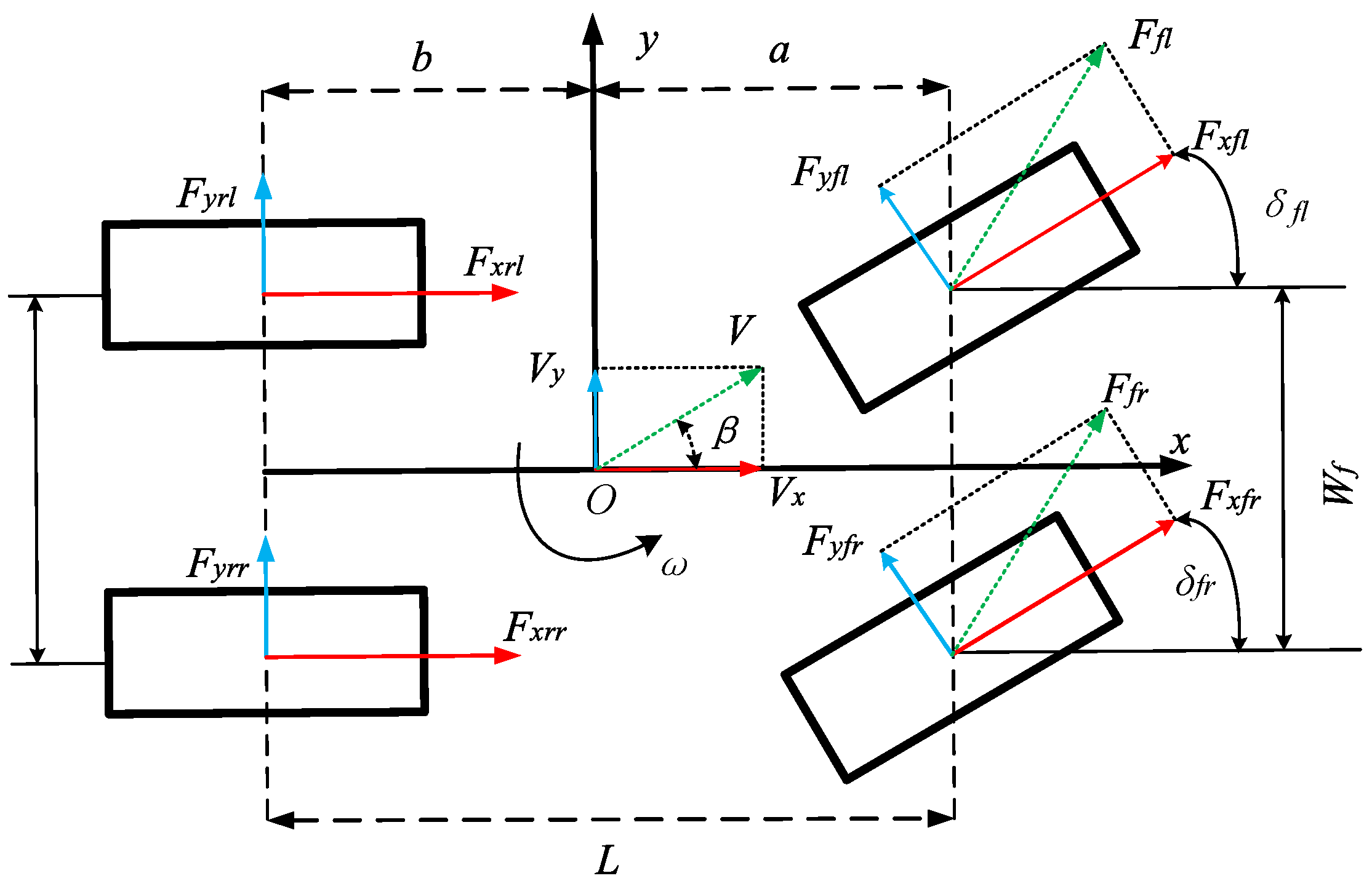
The vehicle dynamics model is crucial for studying torque and force distribution in distributed drive electric vehicles. To this end, a seven-degree-of-freedom reference model is established, incorporating longitudinal, lateral, yaw, and rotational motions of the four wheels [
24]. It is assumed that there is no wheel slip, the front and rear track widths are the same, and the lateral slip angles of the left and right wheels are equal.
Figure 1.
The seven-degree-of-freedom vehicle model.
Figure 1.
The seven-degree-of-freedom vehicle model.
Based on the principles of force and moment equilibrium, the dynamic equations of the seven-degree-of-freedom vehicle model can be expressed as follows:
Longitudinal motion equation:
The relationships between
,
, and
are as follows:
In the equation, represents the total vehicle mass, which is taken as the curb weight; is the longitudinal velocity of the vehicle; is the lateral velocity of the vehicle; is the yaw angular velocity; is the moment of inertia of the vehicle about the z-axis; is the distance from the front axle to the center of mass of the vehicle; b is the distance from the rear axle to the center of mass, andis the rear axle track width; andrepresent the projections of the ground reaction forces(longitudinal tire forces) and (lateral tire forces) onto the vehicle's longitudinal x-axis and lateral y-axis, respectively; is the steering angle of the tire relative to the x-axis,(i=fr,fl,rr,rl); β is the sideslip angle of the center of mass.
Based on the principles of motor drive, the dynamic equations of the vehicle system are given by:
Figure 2.
Longitudinal dynamic model.
Figure 2.
Longitudinal dynamic model.
In the equation, is the output torque of each driven wheel, is the angular velocity of the driven wheel, and r is the tire radius.
3. Model Reference Adaptive Control Strategy
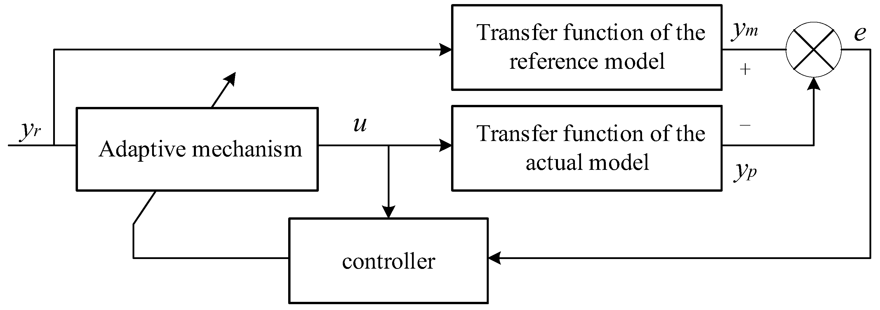
To address the issue of balancing performance and stability in the event of motor failure during high-speed driving, a fault-tolerant control architecture for distributed drive electric vehicles based on MRAC is designed. The actual model and reference model are compared using longitudinal speed
, center of mass sideslip angle
, and yaw angular velocity
to detect faults. When a fault occurs, the torque inputs of the actual and reference models are processed through the MRAC control system, which outputs compensated wheel torques to guide the actual model's motion state towards that of the reference model, as shown in
Figure 3.
3.1. Torque Compensation
Assuming the left front wheel motor fails and its output torque is lost by
, then:
In the equation,is the torque of the left front wheel after loss,is the torque of the left front wheel before loss,is the torque of the right front wheel,is the torque of the left rear wheel,is the torque of the right rear wheel, andis the total torque of the vehicle after the left front wheel failure.
In order for the vehicle to maintain the desired driving state, it is essential to ensure that:
The lateral force loss due to the left front wheel motor failure can be compensated by increasing the output torque of the right front wheel motor, while the loss of longitudinal force can be compensated by adjusting the output of the remaining functioning motors.
In the equation, is the total torque of the vehicle when the left front wheel is not failed, is the lost torque, andrepresents the compensated torque for each wheel.
3.2. Transfer Function and Adaptation Rate
The basic working principle of MRAC system is as follows: The design of the reference model ensures that its state equations are consistent with those of the actual model, achieving complete model matching [
25]. The parameter design of the reference model's state equations indicates how the ideal output of the actual model should respond to the input signal
. Specific parameter values are derived from empirical testing, ensuring that the output
of the reference model aligns with the expected output response of the adjustable system. The adaptive mechanism generates an adaptive control rate based on the difference
between the reference model output and the actual model output
, guiding the actual model's output or state to progressively converge towards that of the reference model.
The transfer function of the actual model can be expressed as:
The transfer function of the reference model can be expressed as:
In the equation, represents an unknown or slowly varying gain, while , , and are known parameters.
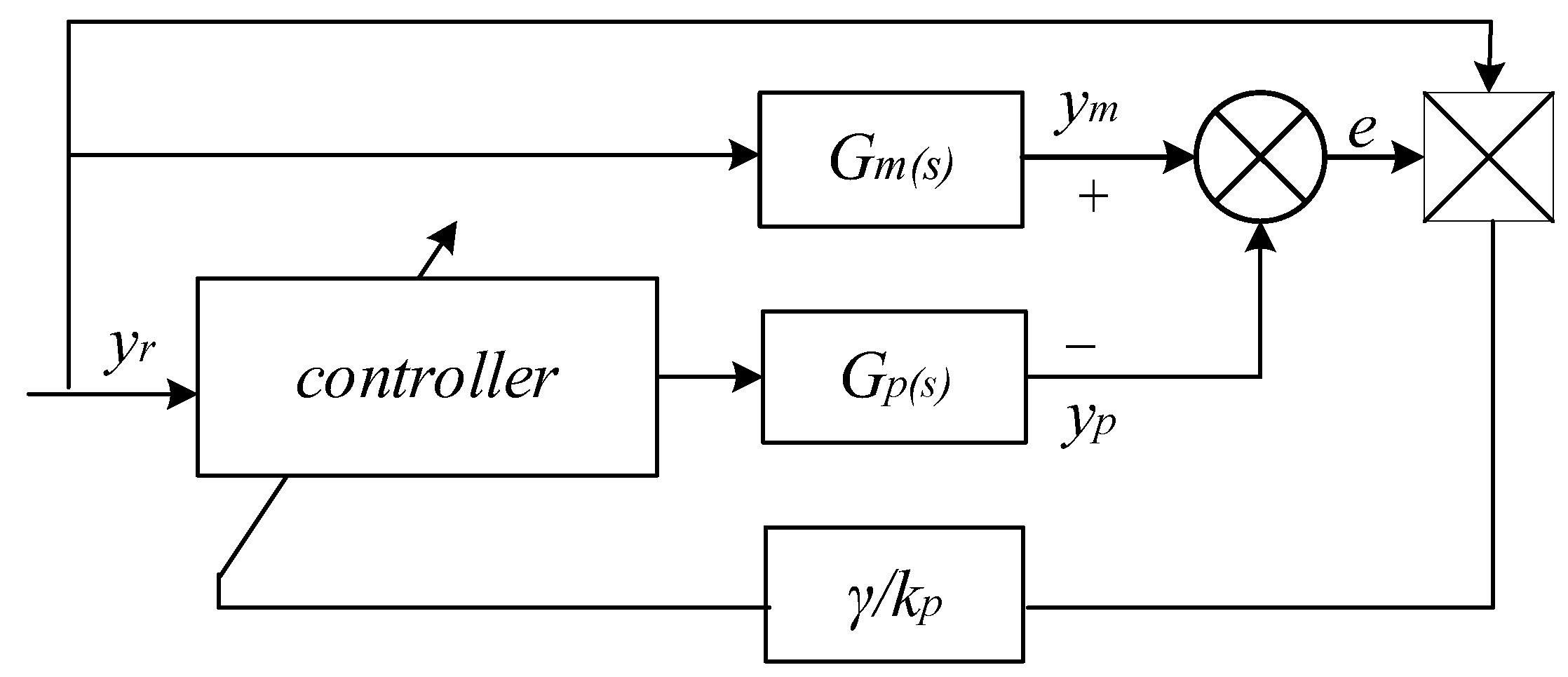
Based on the system structure shown in
Figure 4, the error
can be expressed as:
In the equation, denotes the adjustable gain, represents the output of the ideal model, and signifies the output of the actual model.
The error
can be represented in the state-space observable canonical form as:
The transfer function of the above equation is given by:
There exists a positive definite matrix
,
such that the homogeneous system
is asymptotically stable, and the relationship among
、
、and
satisfies:
If the transfer function is strictly positive real, then the relationship among
,
and
satisfies:
Select a Lyapunov function:
By combining the state-space observable canonical form of the error
with the selected Lyapunov function, we obtain:
To ensure system stability, it is necessary to satisfy the condition
, requiring the parameter adjustment rate to be:
From the above, the adaptive rate of the control system can be obtained as:
By combining the state-space observable canonical form of the error
with the adaptive rate of the control system, the adaptive rate of the adjustable gain for the Lyapunov function-based model reference adaptive control can be derived as:
In the equation, represents the adaptive rate, and .
The adaptive structure of the control system is illustrated in
Figure 5:
The control rate of the system is:
After applying the Laplace transform to Equation 6, the transfer function of the actual model can be expressed in the frequency domain as:
The transfer function of the reference model is given by:
In the equation, represents the moment of inertia of the reference model; denotes the moment of inertia of the drive wheel; is the wheel radius; and signifies the total mass of the vehicle.
3.3. Controller Design
3.3.1. Delay Element
The hub motor plays a crucial role as a power source for distributed drive electric vehicles. In practical control processes, assuming that each hub motor is equipped with a corresponding motor torque controller, the closed-loop characteristics of the motor can be simplified as a delay element:
In the equation, represents the actual output torque of each motor; denotes the response time; and is the motor torque obtained after optimizing the controller. The first-order inertia element described by the above equation simplifies the motor control process, indicating that the actual output torque equals the desired torque calculated by the controller. However, due to the presence of the delay element, any action may exhibit a slight lag, and considering this lag can enhance the precision of torque distribution control.
3.3.2. MRAC Algorithm
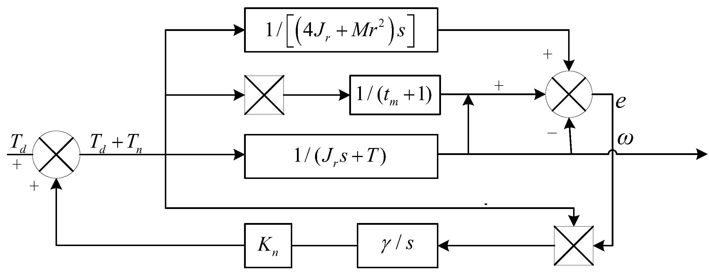
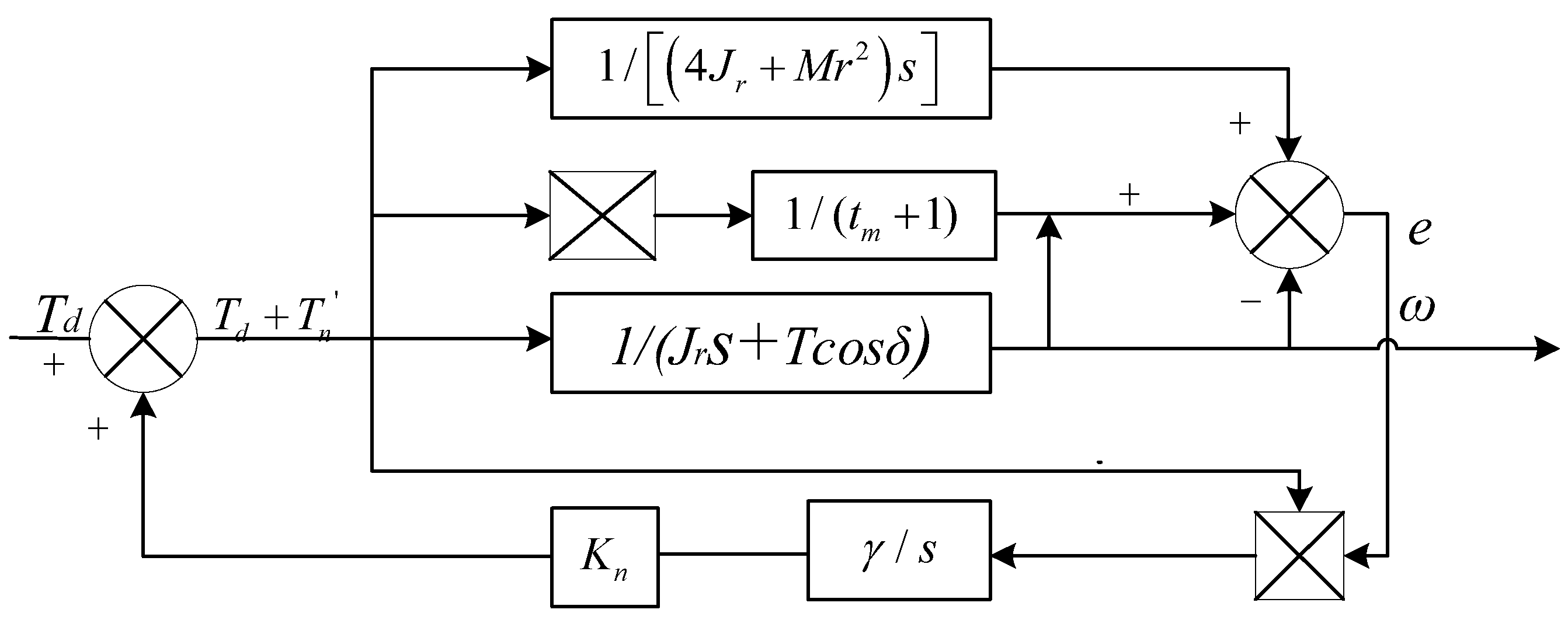
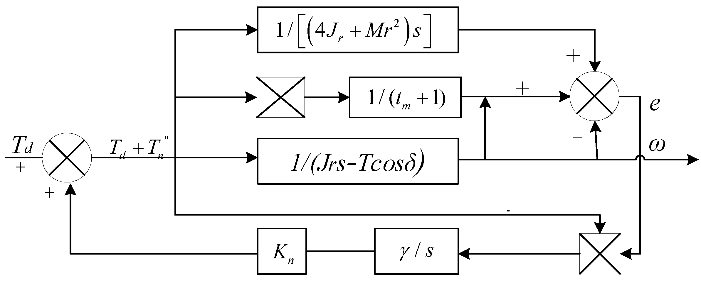
In summary, the model reference adaptive control algorithm for distributed drive electric vehicles is illustrated in
Figure 6,
Figure 7 and
Figure 8.
In the figure, the motor torquefor each wheel serves as the system input, while the angular velocityof each driven wheel is the system output. represents the torque compensation for each motor, is the adaptive rate parameter, is the system adaptive rate, anddenotes the system delay.
4. Simulation and Experimental Results
To further validate the effectiveness of the model reference adaptive control algorithm in accurately compensating torque for the remaining functional motors during a motor failure in distributed drive electric vehicles, this study employs a joint simulation using CarSim and MATLAB/Simulink. The main technical parameters of the vehicle are presented in
Table 1:
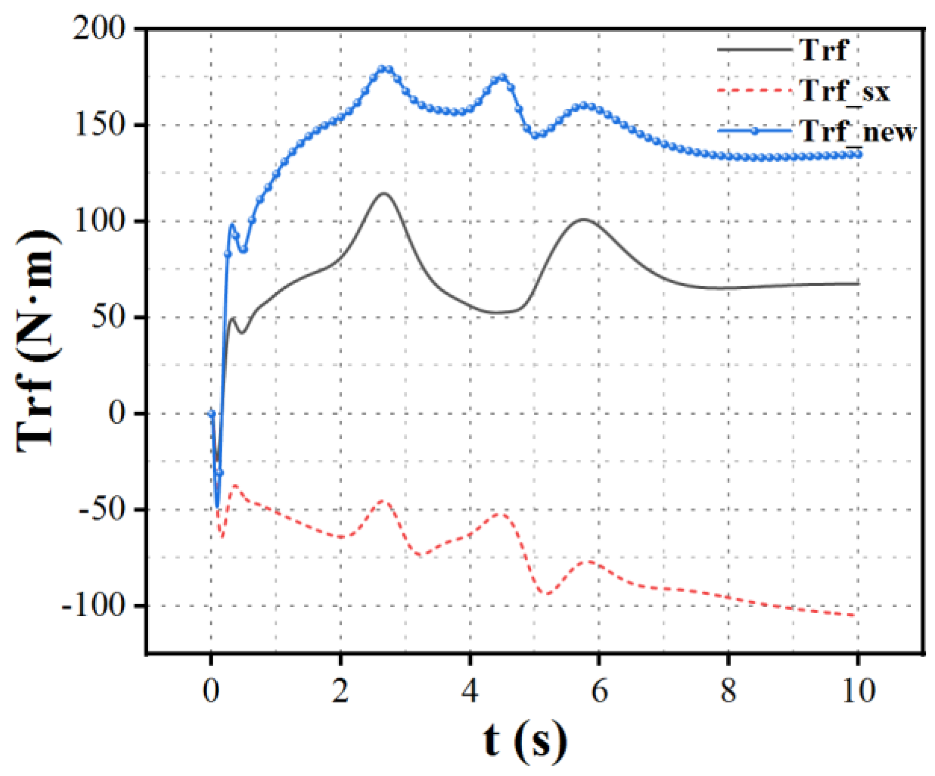
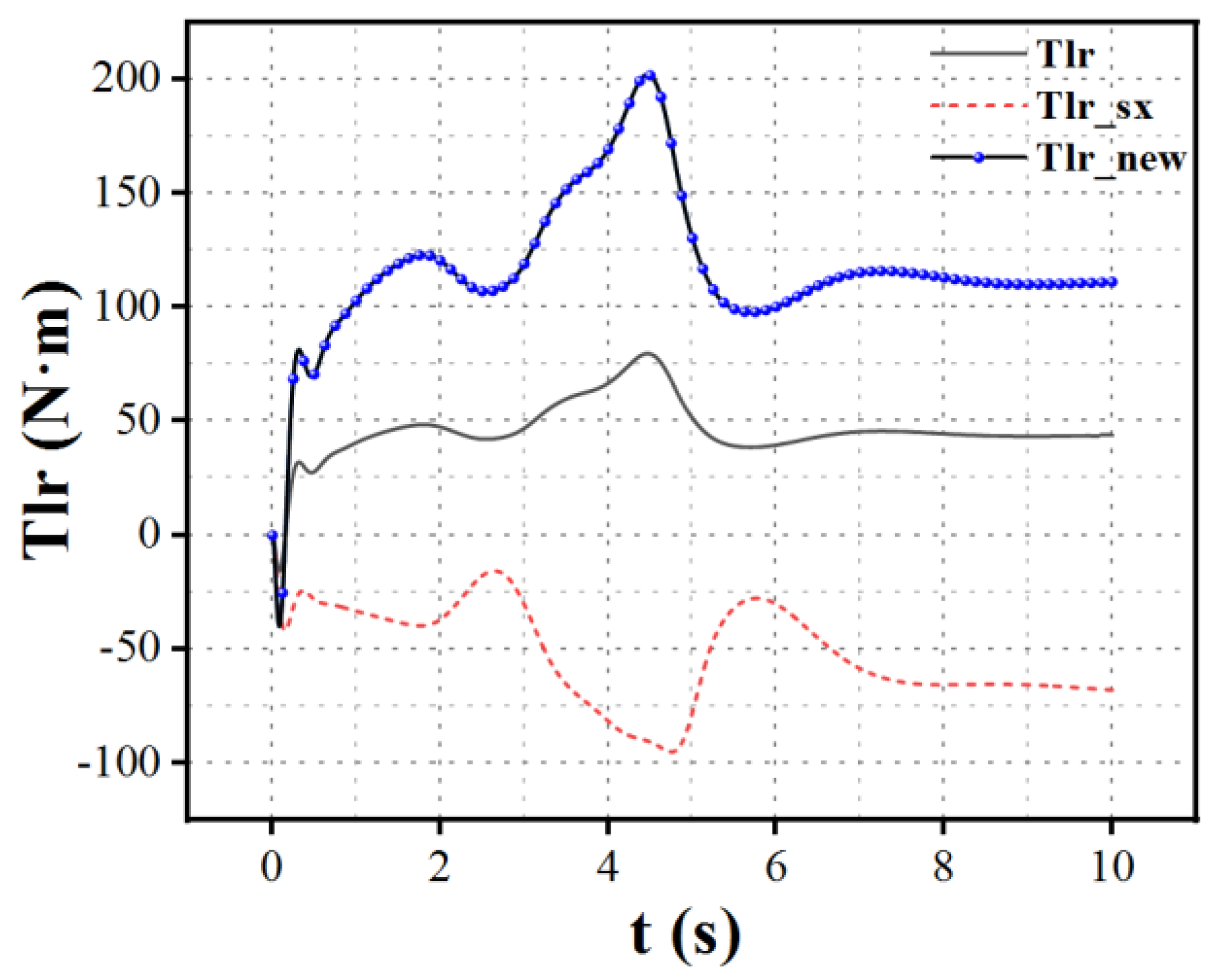
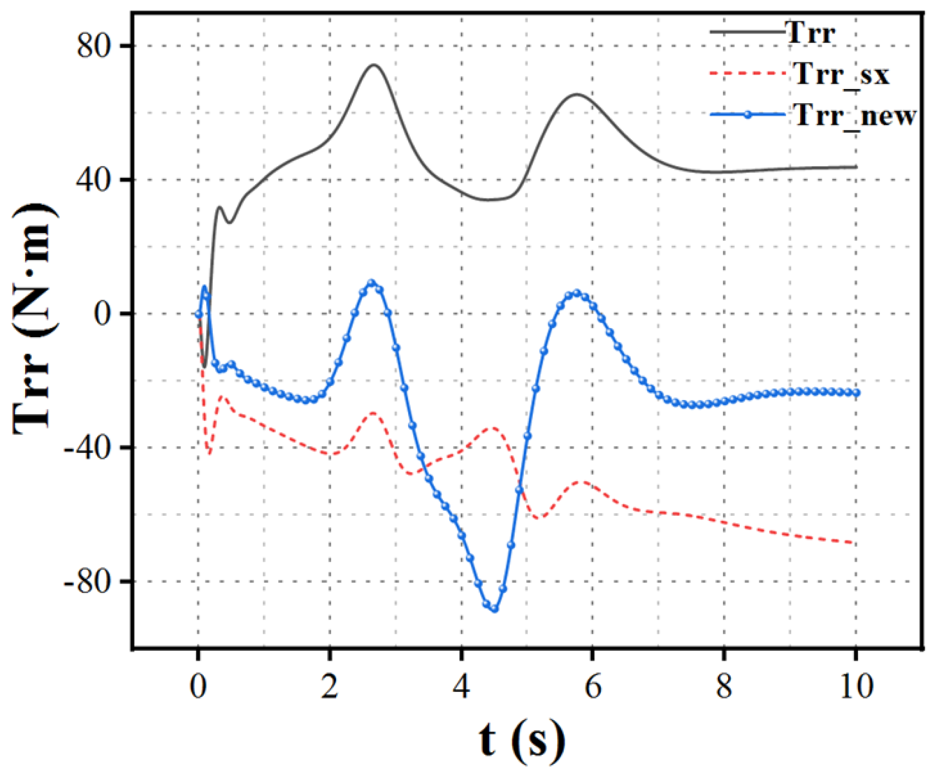
When the left front wheel motor of a distributed drive electric vehicle experiences a complete failure, the remaining wheels receive torque compensation through a model reference adaptive control algorithm, as shown in
Figure 9,
Figure 10 and
Figure 11. Here,
represents the wheel torque under normal operating conditions,
indicates the wheel torque without compensation after the left front wheel failure, and
denotes the compensated wheel torque following the failure.
The simulation results indicate that when the left front wheel fails, the output torque of the remaining wheels significantly decreases before the control algorithm is implemented. This phenomenon occurs because the system operates in a closed-loop state; with the failure of the left front wheel, both lateral and longitudinal forces are compromised. To maintain vehicle stability and prevent accidents, it is necessary to reduce speed, resulting in a noticeable decline in torque for all wheels. After implementing torque allocation based on the MRAC algorithm, the vehicle's actual state approaches the ideal model. Compensation for the loss of lateral force is achieved by increasing the torque output of the right front wheel motor, while the loss of longitudinal force is addressed by adjusting the torque outputs of the left and right rear wheels. This allows the vehicle to maintain its original stable motion state. In the event of a single motor failure, the losses in both lateral and longitudinal forces can be compensated by the torque outputs of the remaining three motors to achieve the desired driving state, ensuring both stability and performance requirements. Similarly, the same strategy can be applied in the case of failures in the right front, left rear, or right rear motors.
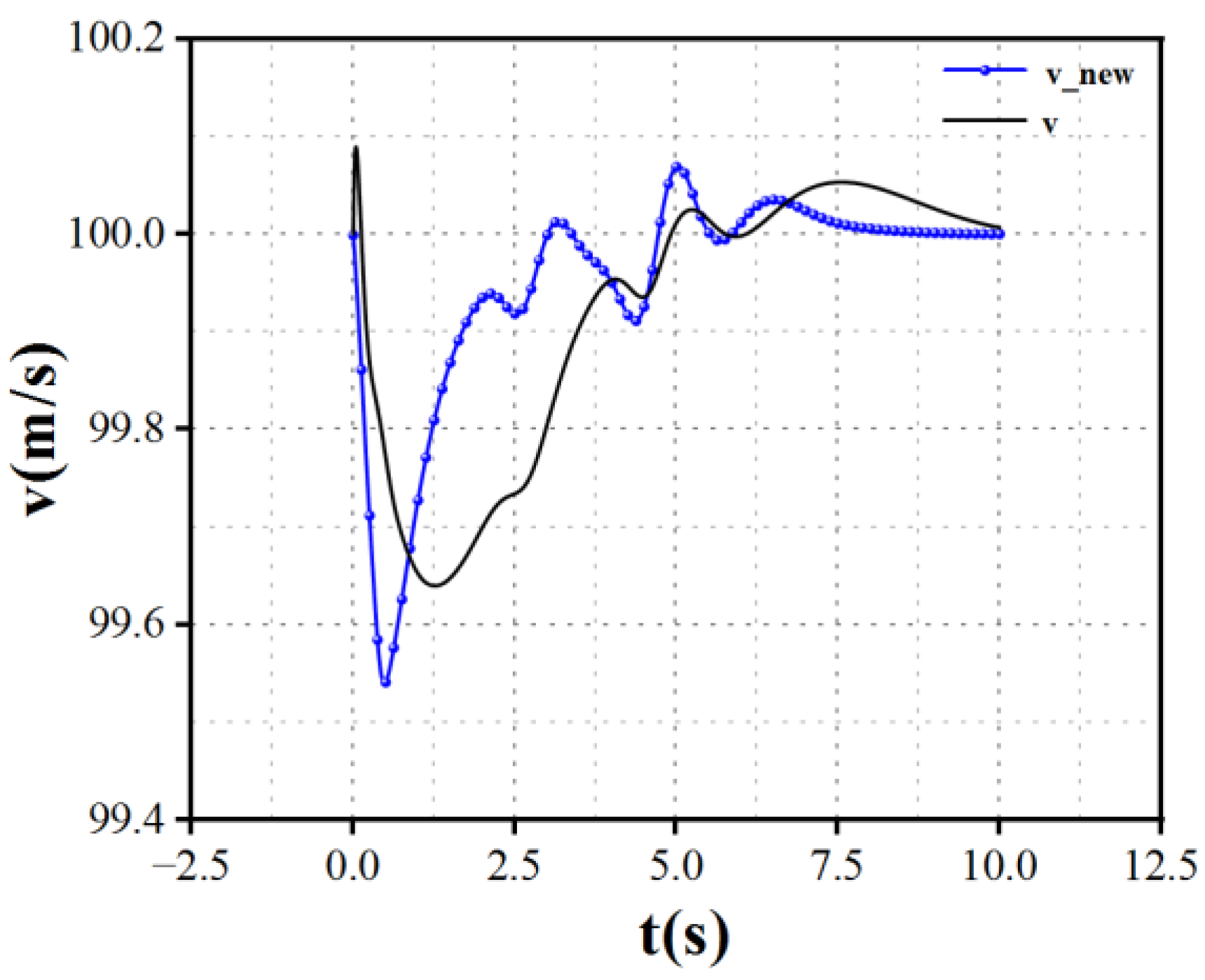
When the left front wheel motor of a distributed drive electric vehicle experiences a complete failure, the vehicle's speed curve is shown in
Figure 12.
represents the vehicle speed without the implementation of model reference adaptive control during the complete failure of the left front wheel.
is the vehicle speed under normal conditions without any failure.
denotes the vehicle speed when torque allocation is implemented with model reference adaptive control after the left front wheel has completely failed.
The simulation results indicate that after the left front wheel fails, the vehicle experiences a significant speed reduction to maintain stability, ultimately stabilizing at 27 km/h. This drastic decrease in performance does not fully leverage the redundancy of motors in distributed drive electric vehicles. When driving on special routes like highways, such a speed reduction can pose serious safety risks. However, after applying the model reference adaptive control algorithm for torque compensation on the remaining motors, the vehicle's speed can remain consistent with that of normal conditions, with the difference not exceeding insert value, effectively mitigating safety hazards associated with sudden speed drops in critical areas.
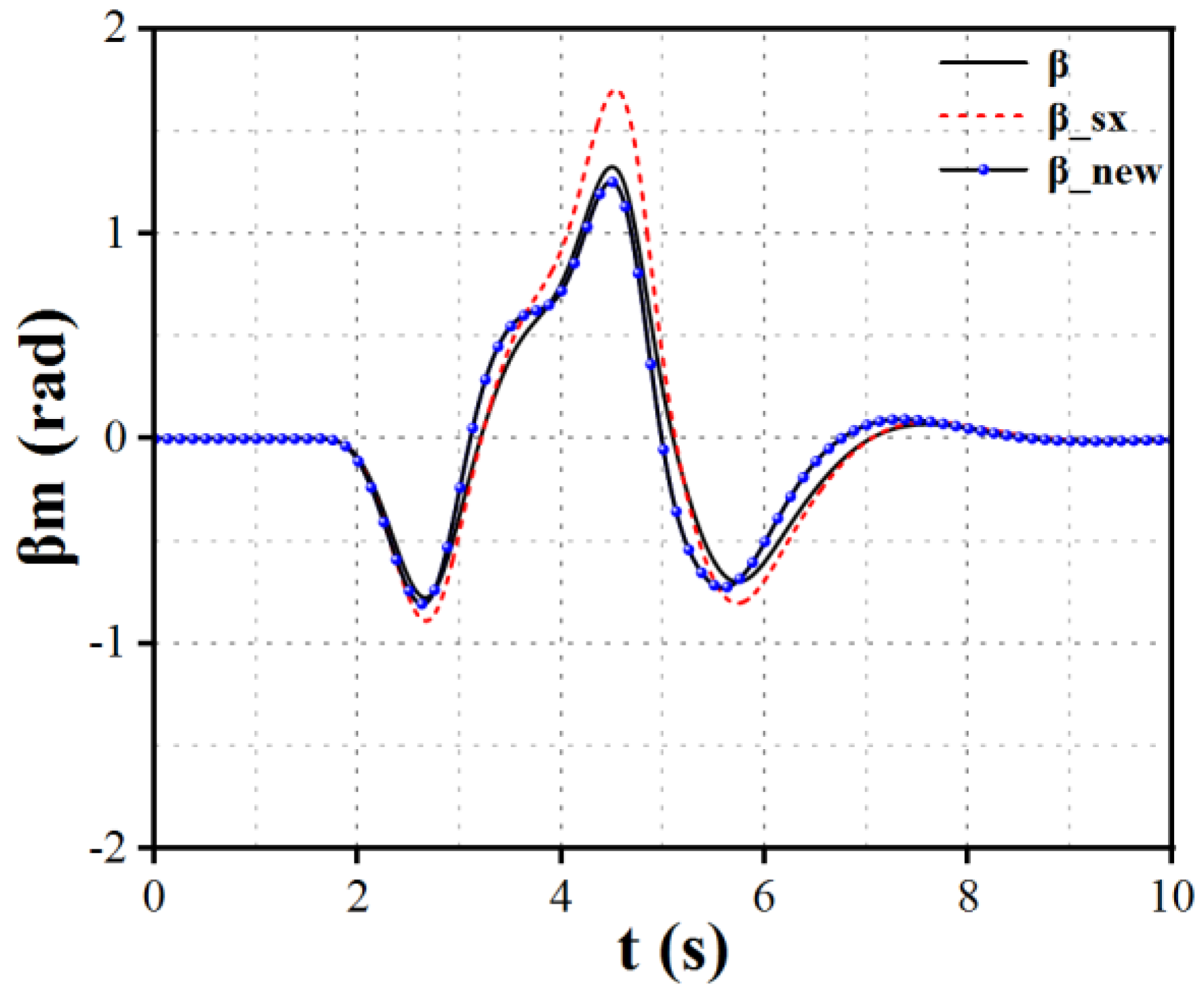
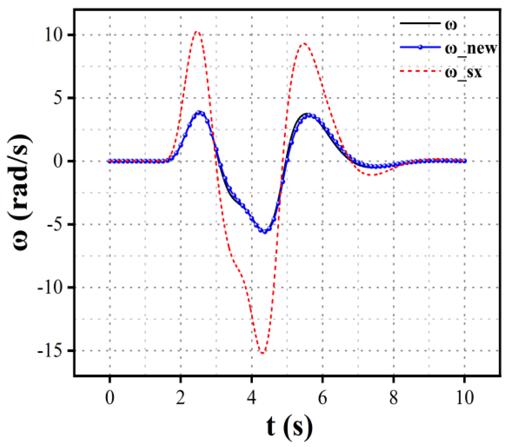
This study selects the yaw rate
and the centroid side slip angle
as indicators to assess vehicle stability. The curves for the vehicle's centroid side slip angle and yaw rate are shown in
Figure 14 and
Figure 15.
represents the centroid side slip angle under normal conditions.
denotes the centroid side slip angle when torque allocation is implemented with model reference adaptive control following the failure of the left front wheel.
is the centroid side slip angle when the left front wheel experiences complete failure without the model reference adaptive control.
indicates the yaw rate under normal conditions, while
represents the yaw rate when model reference adaptive control is applied after the left front wheel failure.
is the yaw rate during complete failure of the left front wheel without model reference adaptive control.
The simulation results indicate that after the complete failure of the left front wheel, the centroid side slip angle and yaw rate without the implementation of model reference adaptive control exhibit significant differences compared to normal operating conditions, which is detrimental to the vehicle's stability at high speeds. In high-speed conditions, an increase in the centroid side slip angle and yaw rate can lead to vehicle rollover, severely jeopardizing the safety of both the driver and passengers. However, when torque allocation is implemented through model reference adaptive control, torque compensation from the remaining functional motors allows the vehicle to maintain stability without reducing speed, even after a single motor failure. This adjustment helps the centroid side slip angle and yaw rate approach ideal model values, thereby enhancing vehicle safety.
5. Conclusions
The main contents are as follows:
A fault-tolerant control strategy for distributed drive electric vehicles based on MRAC has been proposed. A controller considering hysteresis has been designed to enable more precise torque compensation from the remaining wheels during single motor failure at high speeds, enhancing vehicle stability without reducing speed.
Using Lyapunov's second method, an adaptive rate suitable for the torque allocation control system of distributed drive electric vehicles has been derived. This approach ensures the global stability of the system while adaptively adjusting system parameters to reduce errors, thereby enabling the actual model state to converge towards the reference model state.
Joint simulations using CarSim and Simulink demonstrate that under this control strategy, the vehicle speed can be maintained above 99.5 km/h. The yaw rate error compared to the reference model is less than 0.1 rad/s, while the centroid side slip angle error is less than 0.2°, significantly enhancing the vehicle's performance and stability during motor failures.
References
- Ghezzi, M.K. A Dòria-Cerezo, and J. M. Olm. Yaw Moment MRAC with Optimal Torque Vectoring for a Four in-Wheel Motor Ev. Paper presented at the 2018 IEEE International Conference on Industrial Technology (ICIT), 20-22 Feb. 2018.
- Hori, Y. Future Vehicle Driven by Electricity and Control-Research on Four-Wheel-Motored "Uot Electric March Ii". IEEE Transactions on Industrial Electronics 2004, 51, 954–62. [Google Scholar] [CrossRef]
- Wang, R.; J Wang. Actuator-Redundancy-Based Fault Diagnosis for Four-Wheel Independently Actuated Electric Vehicles. IEEE Transactions on Intelligent Transportation Systems 2014, 15, 239–49. [Google Scholar] [CrossRef]
- Alipour, Hasan, Mohammad Bagher Bannae Sharifian, and Mehran Sabahi. A Modified Integral Sliding Mode Control to Lateral Stabilization of 4-Wheel Independent Drive Electric Vehicles. Vehicle System Dynamics 2014, 52, 1584–606. [Google Scholar] [CrossRef]
- Nam, K.; H Fujimoto, and Y. Hori. Lateral Stability Control of in-Wheel-Motor-Driven Electric Vehicles Based on Sideslip Angle Estimation Using Lateral Tire Force Sensors. IEEE Transactions on Vehicular Technology 2012, 61, 1972–85. [Google Scholar]
- Zhang, D.; G Liu, H. Zhou, and W. Zhao. Adaptive Sliding Mode Fault-Tolerant Coordination Control for Four-Wheel Independently Driven Electric Vehicles. IEEE Transactions on Industrial Electronics 2018, 65, 9090–100. [Google Scholar] [CrossRef]
- Silveira, Alexandre, Rui Esteves Araújo, and Ricardo de Castro. Survey on Fault-Tolerant Diagnosis and Control Systems Applied to Multi-Motor Electric Vehicles. Paper presented at the Technological Innovation for Sustainability, Berlin, Heidelberg, 2011//2011.
- Wang, R.; J Wang. Fault-Tolerant Control with Active Fault Diagnosis for Four-Wheel Independently Driven Electric Ground Vehicles. IEEE Transactions on Vehicular Technology 2011, 60, 4276–87. [Google Scholar] [CrossRef]
- Li, Q.; Tang, J.; Zhang, B.; Chen, Y.; Wang, Y. Research on Fault-Tolerant Control of Multi-Actuator for Distributed Drive Electric Vehicles. Automotive Engineering 2023, 45, 2251–2259. [Google Scholar]
- Mutoh, N. Y Takahashi, and Y. Tomita. Failsafe Drive Performance of Electric Vehicles with the Structure Driven by the Front and Rear Wheels Independently. Paper presented at the IECON 2007 - 33rd Annual Conference of the IEEE Industrial Electronics Society, 5-8 Nov. 2007 2007.
- Mutoh, Nobuyoshi. Front-and-Rear-Wheel-Independent-Drive-Type Electric Vehicle (Frid Ev) with Compatible Driving Performance and Safety. World Electric Vehicle Journal 2009, 3, 17–26. [Google Scholar] [CrossRef]
- Zhang, L. Yu, W., Wang, Z., & Ding, X. Fault Tolerant Control Based on Multi-methods Switching for Four-wheel-independently-actuated Electric Vehicles. Journal of Mechanical Engineering 2020, 56, 227–39. [Google Scholar]
- Li, L. , & Wang, B. Fault-tolerant Control Strategy for Distributed Electric Vehicles Based on Fault Diagnosis" Journal of Hubei University of Automotive Technology 2023, 37, 6–11. [Google Scholar]
- Zhang, D.; G Liu, H. Zhou, and W. Zhao. Adaptive Sliding Mode Fault-Tolerant Coordination Control for Four-Wheel Independently Driven Electric Vehicles. IEEE Transactions on Industrial Electronics 2018, 65, 9090–100. [Google Scholar] [CrossRef]
- Tang, H.; Y Chen, and A. Zhou. Actuator Fault-Tolerant Control for Four-Wheel-Drive-by-Wire Electric Vehicle. IEEE Transactions on Transportation Electrification 2022, 8, 2361–73. [Google Scholar] [CrossRef]
- Lu, Yanbo, Jinhao Liang, Weichao Zhuang, Guodong Yin, Jiwei Feng, and Chaobin Zhou. Four-Wheel Independent Drive Vehicle Fault Tolerant Strategy Using Stochastic Model Predictive Control with Model Parameter Uncertainties. IEEE Transactions on Vehicular Technology PP (01/01 2023): 1-13.
- Li, Y. , Hu, H, Qin, Z., Wu, H., & Wang, W. Sensorless control of permanent magnet in-wheel motor based on improved model reference adaptive strategy". Journal of Automotive Safety and Energy 2022, 13, 560–70. [Google Scholar]
- Qiu, J. , Zeng, H., & Shi, C. Self-optimizing control and parameters identification for permanent magnet assisted synchronous reluctance motor. Journal of Electric Machines and Control 2022, 26, 1–8. [Google Scholar]
- Zhang, Y. , Lu, T., Wei, H., Li, Y., & Xu, S. Model reference adaptive torque control of power-assist electric bicycle. Journal of Electric Machines and Control 2022, 26, 115–24. [Google Scholar]
- Zheng, L.; Deng, Z.; Li, Y. Model Reference Adaptive Control for Automotive Semi-active Suspension. China Journal of Highway and Transport 2005, 99–102. [Google Scholar]
- Zhao, Xiuchun, and Ge Guo. Model Reference Adaptive Control of Vehicle Slip Ratio Based on Speed Tracking. Applied Sciences 2020, 10, 3459. [Google Scholar] [CrossRef]
- Elzaghir, Walid, Yi Zhang, Narasimhamurthi Natarajan, Frank Massey, and Chunting Mi. Model Reference Adaptive Control for Hybrid Electric Vehicle with Dual Clutch Transmission Configurations. IEEE Transactions on Vehicular Technology PP (09/12 2017): 1-1.
- Li, J.; Audi, W.; Wang, Y.; Xiong, R. Model Reference Adaptive Stability Control for Independently Driven Electric Vehicles. Journal of Automotive Safety and Energy 2021, 12, 355–63. [Google Scholar]
- Zhu, S.; Lv, C. Distributed Drive Control Technology. Beijing: Mechanical Industry Press, May 2022, p. 16. ISBN 978-7-111-70543-7.
- Nguyen, N.T. Introduction to Model Reference Adaptive Control. Translated by Zhao, L., & Shi, Z. Beijing: Mechanical Industry Press, January 2020, p. 1. ISBN 978-7-111-64339-5.
|
Disclaimer/Publisher’s Note: The statements, opinions and data contained in all publications are solely those of the individual author(s) and contributor(s) and not of MDPI and/or the editor(s). MDPI and/or the editor(s) disclaim responsibility for any injury to people or property resulting from any ideas, methods, instructions or products referred to in the content. |
© 2024 by the authors. Licensee MDPI, Basel, Switzerland. This article is an open access article distributed under the terms and conditions of the Creative Commons Attribution (CC BY) license (http://creativecommons.org/licenses/by/4.0/).
