1. Introduction
The difficulty of reading from a screen in harsh light conditions such as outdoors, is a well-known issue to most display users. The outdoor usage of a smartphone, for example, will often lead to the user increasing the brightness to its maximum. A notification will pop up to warn the user that using a high brightness will drain the battery. If we were able to increase the readability of the screen without having to increase the screen brightness, we would be able to significantly reduce energy consumption of smartphones and other mobile devices. Other use cases that struggle with outdoor readability are displays in the automotive and aviation sector or even outdoor signage. In combination with the increased usage of screens, averaging nearly 7 hours per day globally across mobile phones, computers, notebooks, automotive displays and TVs, [
1] there is an increased interest in minimizing reflections, or glare, to increase the readability. Harsh reflections from e.g., a smartphone screen are the result of a glossy surface that reflects the light directly back to the user’s eye by specular reflection. A possible way to reduce front side reflections from ambient lighting is by the use of anti-glare functionality. An anti-glare screen works by adding a textured surface that reduces specular reflection and increases diffuse reflection (see
Figure 1). Thus reducing the intensity of glare, resulting in improved readability and reduced eye strain [
2].
An additional layer placed in between the display and the viewer will affect the image quality. Therefore, there are several design criteria that should be taken into account when designing anti-glare textures, such as gloss and haze level, sparkle, distance from pixels and the Pixels Per Inch (PPI). [
3] In general, there is a tradeoff between achieving a glare reduction and maintaining a good image quality, such as reducing the glare, but keeping a high transmittance for a clear image.
One important aspect to consider is sparkle: sparkle is the visual effect that results from the interaction of light with the display pixel matrix and the anti-glare surface that contains an irregular micro texture. It occurs when the AG texture size is similar to the pixel geometry within the display. As display pixels become smaller and approach the size of the anti-glare texture, light emitted from each display pixel is refracted by the anti-glare surface texture, which will lead to interference and scattering.[
4,
5] To the user, this becomes visible as a grainy or ‘sparkly’ displayed image with varying colors and intensity and a random distribution across the display. This effect is very sensitive to a changing viewing angle and therefore becomes more obvious when the viewer moves with respect to the display.
As development for displays and pixel sizes is continuously ongoing, manufacturers are challenged to enable customization of the anti-glare features to be able to match them with the different types of displays and pixel sizes.
Currently, anti-glare surfaces are traditionally achieved through e.g., sandblasting, wet etching, sputtering, spraying or a combination thereof [
6]. However, these techniques are restricted in the design of the textures due to constrains in process adjustments. Especially as display pixel sizes get smaller, such design freedom becomes more critical. To unlock design freedom and achieve optimal anti-glare textures and durable performance, this work describes a novel method of creating anti-glare surfaces: Nanoimprint Lithography (NIL) based replication of textures generated through Laser Beam Lithography (LBL). Rather than letting the geometry of the anti-glare texture be dictated by the production process, this combination of techniques allows manufactures to design and optimize an anti-glare texture to give the best optical performance and match with the display. Next to being able to create the most optimal anti-glare texture itself, this combination of techniques also allows for easy ‘selective patterning’. This means that it is easily possible to e.g., keep camera holes for a smartphone or tablet screen untextured. With conventional techniques, this would require masking and this leads to a higher complexity of the production process as well as higher energy and material consumption. An additional advantage of this fabrication method is the fact that every product is identical. With conventional techniques, the texture is a result of random processes and therefore every product is different. Using LBL in combination with NIL would give a reproducibility that cannot be achieved with the conventional fabrication methods.
To showcase this novel fabrication method, Raith Laser Systems BV and Morphotonics BV combined their efforts and techniques (
Figure 2). Firstly, together with PlanOpsim, four different types of anti-glare textures were modeled and the grayscale images were used by Raith to fabricate the master mold using LBL. The photoresist master was used to create a nickel shim that was subsequently used by Morphotonics for the replication onto a glass substrate. The results of this full cycle from design to finished products are described in this work.
2. Materials and Methods
2.1. Texture Design
Several anti-glare textures were designed and modeled. Different texture shapes and feature sizes were modeled and the resulting haze and gloss levels were measured. To verify the model, several commercially existing anti-glare textured surfaces were also modeled and the gloss and haze values were verified by experimental measurement. Finally, four anti-glare textures were chosen for the mastering and replication.
2.2. Mastering by LBL
Exposure optimization and master fabrication was performed with a PICOMASTER XF 200 tool (Raith Laser systems, Sint-Oedenrode) on 10 inch glass plates coated with 3 µm thick GS5000 resist (Telic company, Santa Clarita). Development of the masters was performed with AZ400 K developer (MicroChemicals GmbH, Ulm). Confocal microscopy was performed with Laser Scanning Confocal Microscope VK-X1000 (Keyence, Osaka).
The exposures parameters chosen for the master fabrication are indicated in
Table 1.
2.3. Replication by NIL
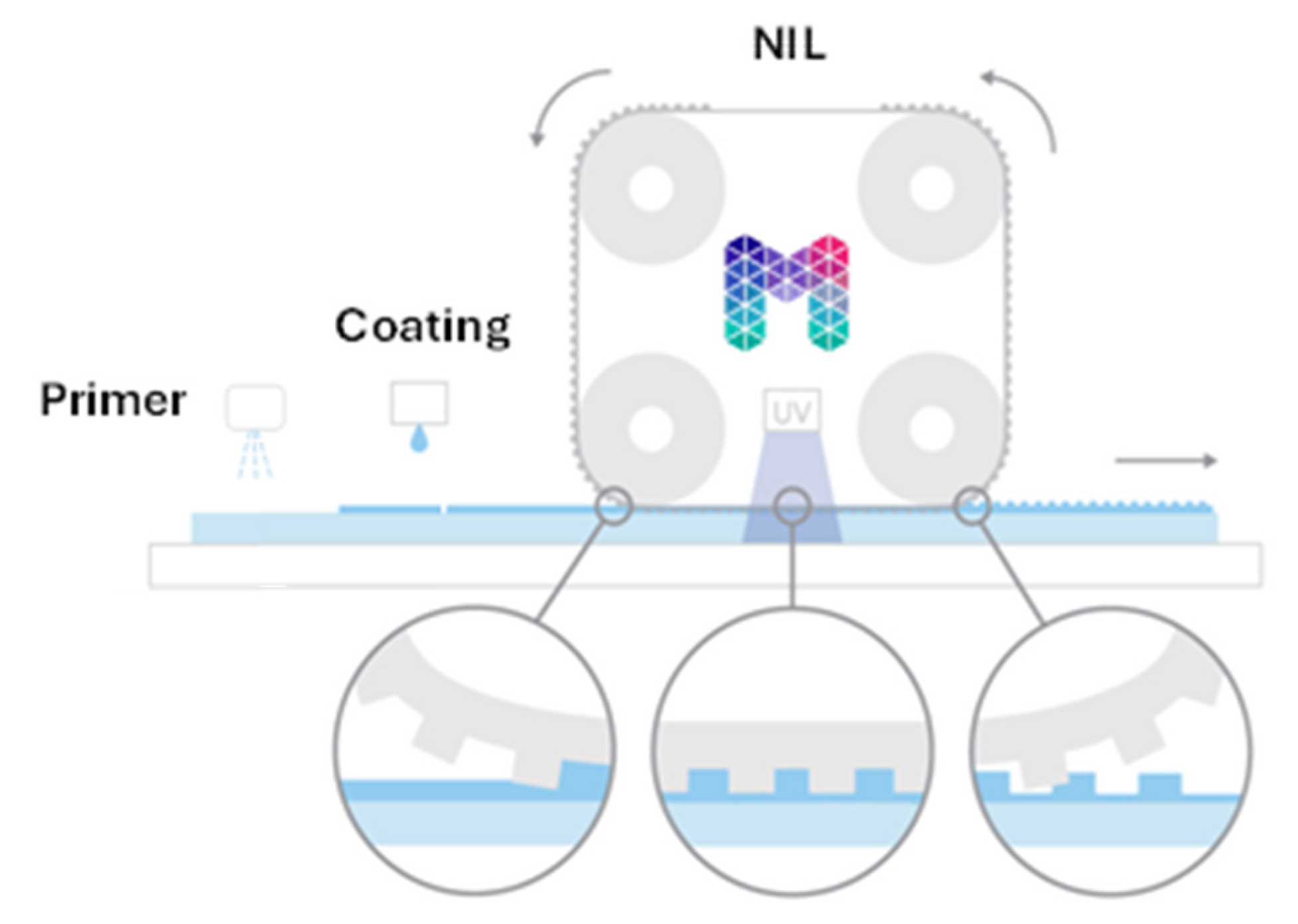
Replication was performed on Morphotonics’ Portis NIL600 Roll-To-Plate (R2P) large-area nanoimprinting equipment. A schematic representation of the R2P process can be seen in
Figure 3. It consists of four rollers that carries a belt that holds a flexible stamp with the inverse of the required texture. The photoresist master from Raith was used to create a nickel shim (Ni shim), and in this case, the Ni shim was used by Morphotonics to create a flexible stamp. Morphotonics uses proprietary methods to give the flexible stamp anti-sticking properties to ensure a proper release of the flexible stamp from the imprinted anti-glare layer for over a thousand times.
Before imprinting, an adhesion promoter is applied to the glass substrate to achieve good adhesion between the glass substrate and imprint resin. As a substrate, Corning EAGLE XG glass of 0.5 mm thickness and size 220x220 mm
2 was chosen. After the primer application, the right amount of resin is applied by dispensing. The dispensing method of Morphotonics allows for highly accurate positioning of resin only where it is needed. As it allows for easy optimization and precisely controlling the amount of resin, it produces no resin waste, which is a big advantage compared to a coating method such as spin coating. For the imprints made in this work, a hardcoat resin was chosen (MM1130B2, Morphotonics) with a viscosity of 95 cP. After application of the resin, the imprint process is started. Speed, pressure and gap of the two lower rollers (in
Figure 3: imprint on the left and delamination on the right) can be precisely controlled for high quality and reproducible imprints. The imprint roller laminates the flexible stamp onto the substrate, while the resin fills the texture on the flexible stamp. After lamination, the resin is cured in between the imprint and delamination roller through exposure with UV light. The equipment can imprint multiple different types of textures and texture sizes within one imprint cycle. The final layer thickness is determined by the viscosity of the resin, the imprinting speed and pressure. For this application, an imprinting speed and pressure of 200 mm/min and 10 N/cm respectively, were chosen.
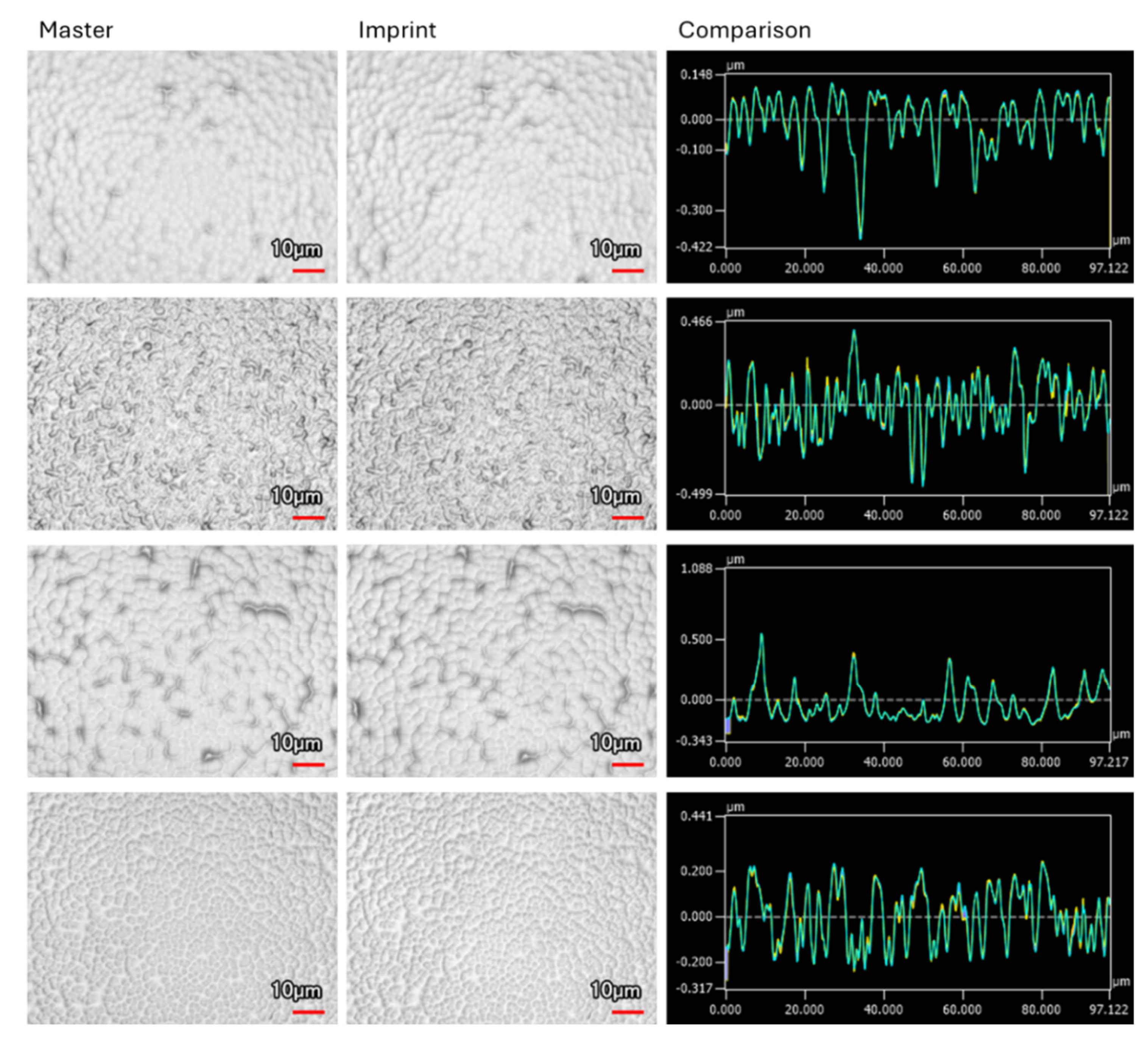
The final imprints were characterized for their replication fidelity by measurements with a laser scanning confocal microscope VK-X1000 (Keyence). Positions of measurements were chosen such that it was possible to measure the exact same position on both the master and the imprint. The Keyence software allows for overlapping of the measurements of the master and the imprint for an accurate comparison and to determine the replication fidelity.
3. Results and Discussion
3.1. Texture Design
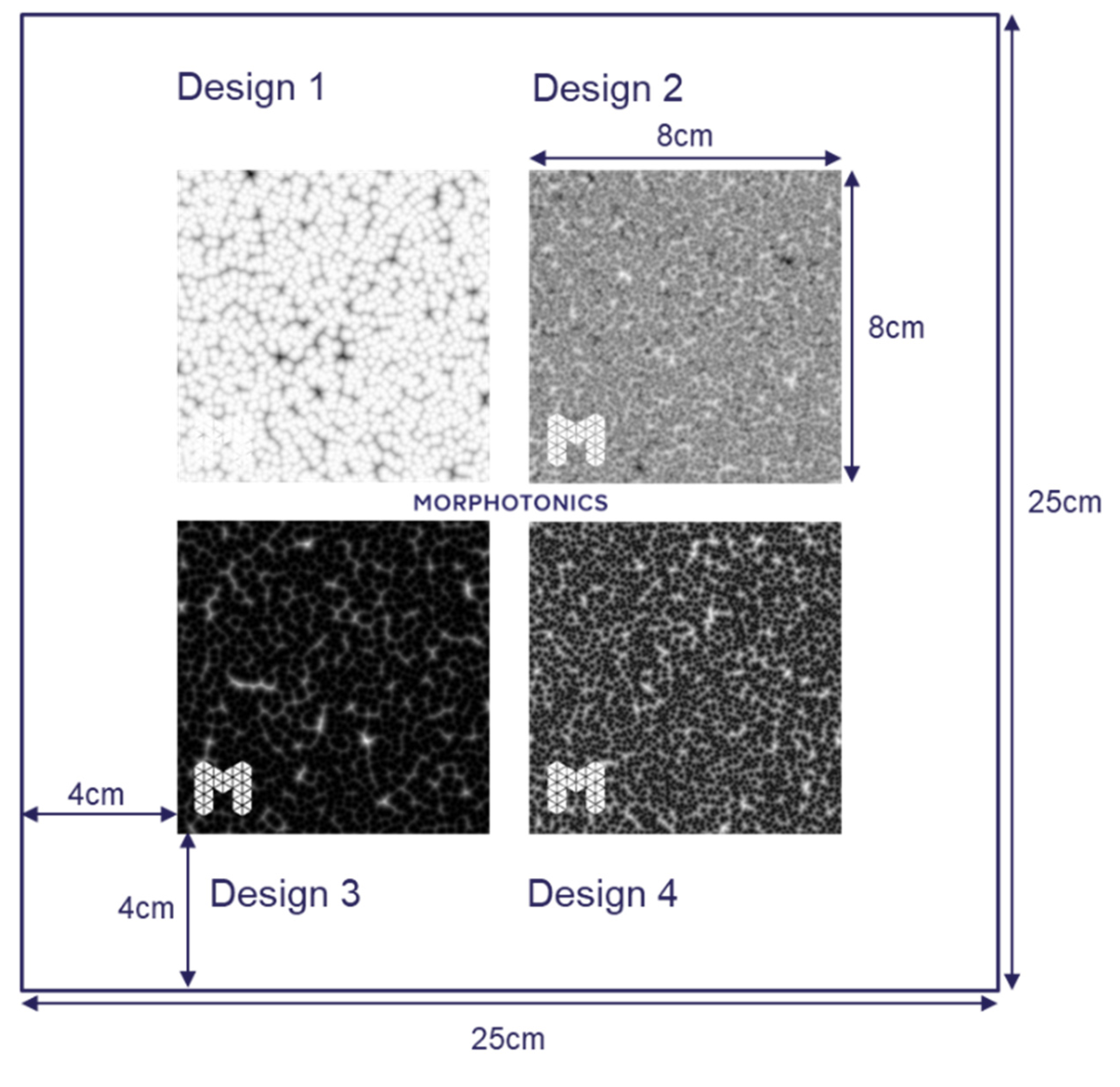
Four different textures were modeled, of which four grayscale images were the result. These grayscale images and the designed layout can be seen in
Figure 4. All textures have a feature size of approximately 6 µm in width and 1-1.5 µm in height. Design 1 and design 3 are the opposite polarity of each other, whereas design 2 is a combination of the features in design 1 and design 4. While there is room for further optimization of the anti-glare textures, we showcase the versatility and the endless possibilities for designing, mastering and replication of anti-glare surfaces using a combination of LBL and NIL. To also showcase the possibility of selective patterning, the Morphotonics logo was added to the textured area with the request for Raith to keep these areas untextured.
3.2. Mastering by LBL
To evaluate the optimal exposure parameters the four different modeled textures were exposed 7 times each as 10x10 mm squares choosing different exposure doses (from 40 to 100 mJ/cm
2 in 10 mJ/cm
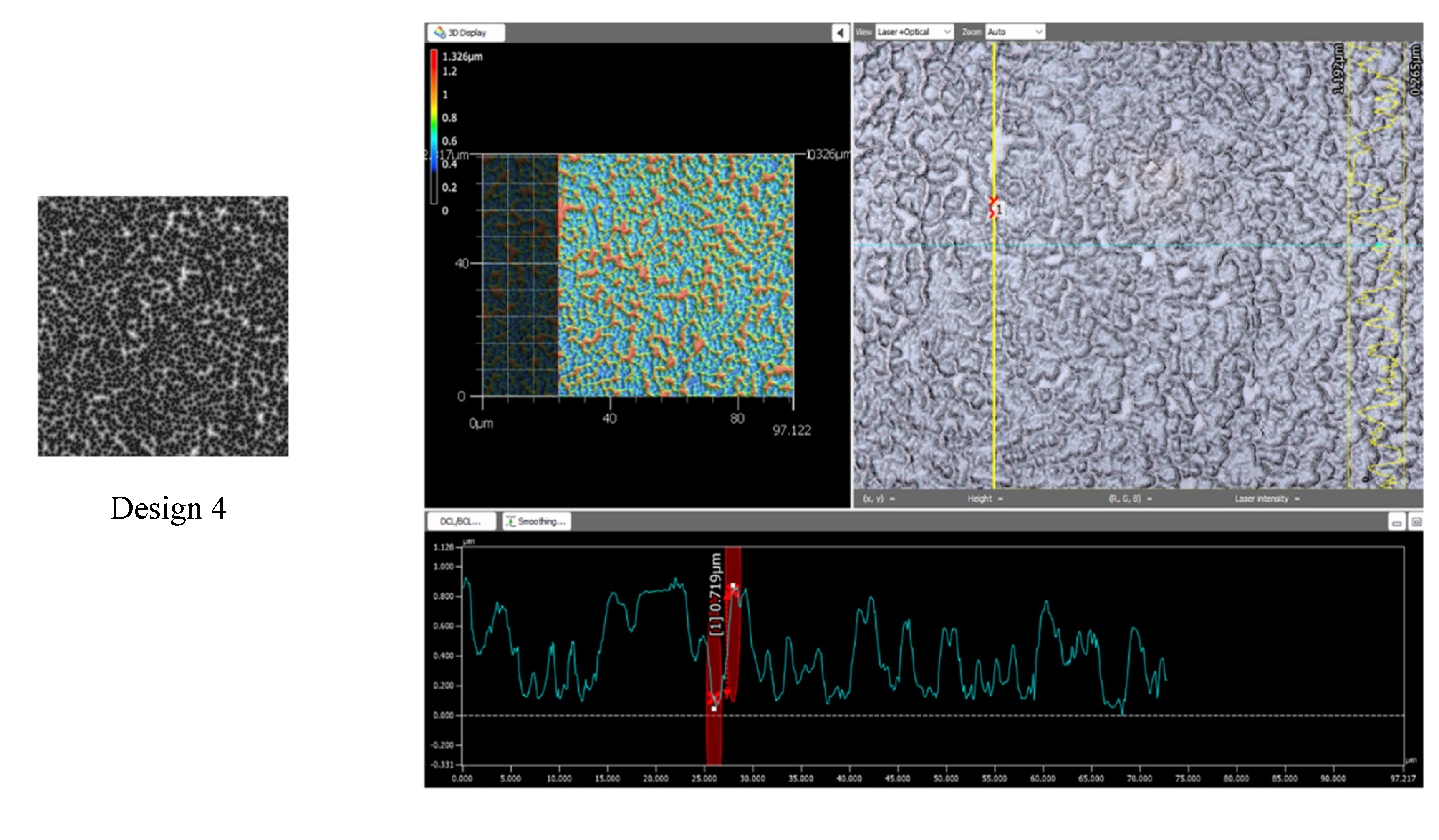
2 steps). After development, the relevant feature height was checked with confocal microscopy (
Figure 5) and the best exposure dose was selected.
After this step, the 4 different designs were written as 80x80 mm2 squares using the optimal dose selected in the exposure optimization test on a 10-inch plate.
3.3. Replication by NIL
The Ni shim that was made after electroforming of the photoresist master created by Raith was used for fabrication of the flexible stamp. All four textures were properly replicated within one imprint cycle.
The imprints were made on 220x220 mm
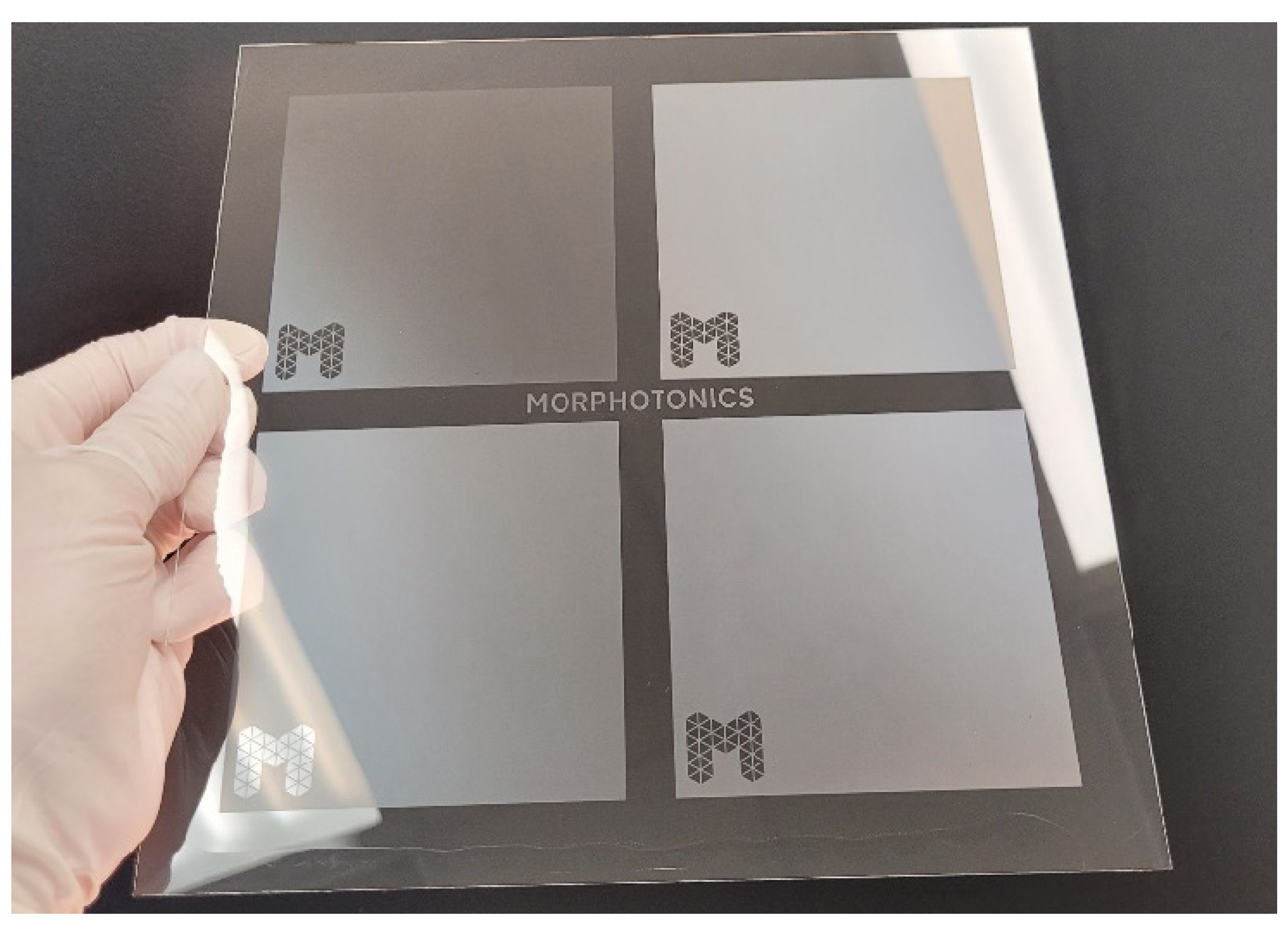
2 glass. For this, the glass substrate was placed on top of a larger (460x350 mm) glass substrate that was used as a carrier. The resin is dispensed at the start of the substrate as it is pressed forwards in the lamination step within the imprint cycle. During lamination, the resin is spread across the substrate and fills the texture on the stamp. UV curing and delamination was successful and lead to a properly replicated texture as can be seen in
Figure 6. This image also shows the anti-glare effect as the reflection of the light is less harsh within the textured areas compared to the flat areas next to the textured squares. This clearly shows the capability of the anti-glare textures to decrease the amount of specular reflection and increase the diffuse reflection.
The imprint was characterized by means of confocal microscopy measurement. The imprint and master were measured at the exact same position, which allows for perfect overlapping of the measurements of the master and imprinted texture. The results are shown in
Figure 7. This figure shows a nearly perfect overlap between the measurement of the imprint (yellow line) and the master (blue line) for all four textures. Small deviations are a result of the polymerization shrinkage of the resin, which is inherent to the materials used in the replication process. As the amount of polymerization shrinkage is reproducible, this can be compensated for in the master design.
4. Conclusions and Recommendations
In conclusion, while existing anti-glare technologies have been constrained by limited design flexibility, the novel combination of LBL and NIL presented in this work offers a significant leap forward. This process provides unmatched versatility in design, enabling precise customization of both textured and untextured areas, and achieves high accuracy and replication fidelity. The ability to incorporate selective patterning without the need for complex masking greatly simplifies production, reducing energy and material consumption. Looking ahead, efforts should focus on enhancing the durability of the final product. This could involve applying a hardcoat layer or using the imprinted texture as an etching mask, with the goal of leveraging the inherent advantages of glass substrates, such as superior optical properties and the absence of an interface. These developments will pave the way for more durable, energy-efficient, and visually improved screens.
References
- Backlinko Team, “Revealing Average Screen Time Statistics.” Accessed: Sep. 30, 2024. [Online]. Available: https://backlinko.com/screen-time-statistics.
- K. Kaur et al., “Digital Eye Strain- A Comprehensive Review,” Oct. 01, 2022, Adis. [CrossRef]
- B. Sitter, “Design Criteria in the Development of Anti-Glare Surfaces,” 2020. [Online]. Available: https://www.display-.
- M. E. Becker and J. Neumeier, “Optical characterization of scattering anti-glare layers,” in 49th Annual SID Symposium, Seminar, and Exhibition 2011, Display Week 2011, 2011, pp. 1038–1041. [CrossRef]
- “Method for Repeatable Measurement of Sparkle in Anti-Glare Displays Defining Quality Control Standards Based on Human Perception 2 I Radiant Vision Systems, LLC".
- Charles Warren Lander, Timothy Edward Myers, Kelvin Nguyen, and Alan Thomas Stephans, “Anti-Glare Surface Treatment Method and Articles thereof,” 2017 Accessed: Sep. 30, 2024. [Online]. Available: https://patents.googlecom/patent/US9651720B2/en.
|
Disclaimer/Publisher’s Note: The statements, opinions and data contained in all publications are solely those of the individual author(s) and contributor(s) and not of MDPI and/or the editor(s). MDPI and/or the editor(s) disclaim responsibility for any injury to people or property resulting from any ideas, methods, instructions or products referred to in the content. |
© 2024 by the authors. Licensee MDPI, Basel, Switzerland. This article is an open access article distributed under the terms and conditions of the Creative Commons Attribution (CC BY) license (http://creativecommons.org/licenses/by/4.0/).


