1. Introduction
Metered Dose Inhalers (MDIs) have been widely employed in managing various respiratory disorders, including asthma and chronic obstructive pulmonary disease (COPD) [1-3]. The efficiency of MDI spray delivery is a critical factor in ensuring that patients receive the intended dose of medication [
4,
5]. This efficiency is influenced by various factors, including the physical properties of the formulation, the design of the device, and environmental conditions [
6,
7]. The evaporation process in MDI sprays begins immediately upon actuation and continues as the aerosol travels through the air [
8]. Also, current inhales deliver low doses to the peripheral airways, especially in constricted lungs [
9,
10].
Studies of evaporation on MDI performance have primarily focused on experimental approaches [
11,
12,
13]. Martin et al. [
14] recorded droplet evaporation using a microscope camera in a chamber at 37
oC and either 100% or 10% relative humidity. Their recordings suggested that the evaporation rate of HFA-based formulations likely remain unchanged under high relative humidity and that evaporation might not be responsible for increased deposition in highly humid, confined airways. Similarly, Legh-Land et al. [
15] measured the rapid evaporation of droplets that were trapped by the electrodynamic field and illuminated by the laser. They observed that droplets with water activity of 0.98 upon inhalation produced very different dose deposition patterns than those with lower water activities. They emphasized that droplet size variation before inhalation affected both the regional and total deposition. Sheth et al. [
16] tested MDI formulations with varying cosolvent properties in the U.S. Pharmacopeial induction port (USP) and the Alberta Idealized Throat model. Their results suggested that MDI performance was sensitive to the cosolvent concentration and vapor pressure, as well as the selection of the throat model. Also, the droplet lifetime closely correlated with both the throat deposition and fine particle fraction, suggesting that evaporation plays a crucial role in the drug delivery efficacy via metered dose inhalers (MDIs).
Shemirani et al. [
17] investigated the effect of ambient humidity on regional delivered dose in the Alberta Idealized Throat model with solution and suspension MDIs. For both BDP HFA134a and Flixotide MDIs, the mouth-throat deposition increased with increasing RH. For the solution MDI (BDP HFA134a), increasing temperature from 20°C to 40°C reduced the throat filtration and enhanced lung delivery efficiency, but had no influence on the suspension MDI (Flixotide). Note that quick droplet evaporation (i.e., freeze drying) has been commonly used to produce porous particles, with a threshold for ambient RH value to produce porous particulate matters for a given formulation [
18,
19,
20,
21,
22,
23].
One major challenge in these experimental studies was that the spray size distribution changes substantially during the measurement process. Stein [
24] suggested that the measured size distribution was sensitive to the degree of evaporation prior to the measurement, which influenced the number of modes in the size distribution. The MDI aerosols collected in the cascade impactor exhibited a bimodal profile when preceded by a USP but exhibited a monomodal profile when preceded by a large chamber. The large droplet mode with the USP inlet was from the same monomodal distribution that had not fully evaporated. Moreover, traditional
in vitro methods often exhibit little correlation with
in vivo performance in clinical studies, emphasizing the need for new approaches to measure evaporation rates more accurately [
25,
26,
27,
28].
Researchers increasingly leverage computational fluid dynamics (CFD) to study evaporation effects in MDIs. Longest and Kleinstreuer [
29] assessed the performance of various evaporation models across a spectrum of droplet volatilities, including a multicomponent evaporation model. Their work demonstrated that the specific heat of the volatile phase is an important influencing factor on evaporation and needs to be considered for respiratory droplets containing volatile species. Longest et al. [
30,
31] extended this approach by coupling CFD simulations with whole-airway deposition models. They showed that accounting for evaporation/condensation and size change during particle transport significantly improved predictions of regional deposition fractions compared to models assuming fixed particle sizes. Zanutto et al. [
32] simulated the heating and evaporation process of ethanol/iso-octane droplets by incorporating non-ideal mixture thermodynamics and heat transfer effects inside the droplet. Their work revealed the significant impact of formulation composition, particularly the presence of cosolvents like ethanol, on evaporation rates and final particle size distributions. Talaat et al. [
33] developed a multiscale model that linked near-atomizer spray dynamics with pulmonary deposition predictions. Their work highlighted the importance of considering the entire spray evolution process, as well as the dosimetry method, for accurate performance assessment of polydisperse aerosols.
While significant progress has been made in understanding evaporation effects on MDI performance, several challenges remain. Most existing models treat evaporation dynamics and dosimetry as separate phenomena, potentially missing important interactions [
34,
35,
36]. Particularly, droplet size variation due to evaporation or condensation will not only affect its motion and deposition site, but also its own mass and drug concentration. There is a need for validated, integrated computational approaches that can accurately predict delivery efficiency in the targeted region.
This study aims to address this gap by developing and validating an integrated computational approach that combines high-fidelity modeling of evaporation dynamics with mouth-lung dosimetry predictions. Specific aims include:
Develop a CFD model that accurately captures the droplet evaporation process and validates the model against existing literature data
Apply the validated model to assess the impact of droplet evaporation on droplet transport and deposition in the respiratory tract.
Compare the dosages received in varying regions based on three different methods: count-based, mass-based, and drug based.
Compare the regional and local deposition rates for MDI spray droplets with and without evaporation.
2. Materials and Methods
2.1. Mouth-Lung Model
The mouth-lung model used in this study has been previous reported in Talaat et al. [
37] and is briefly described here. The mouth geometry was reconstructed from an oral impression [
38]. The pharynx and larynx were segmented from CT images of a 53-year-old female subject, with comprehensive dimensions presented in [
39]. For the lung network, an in-house algorithm called
Lung4Cer, developed by Kitaoka et al. was employed [
40,
41,
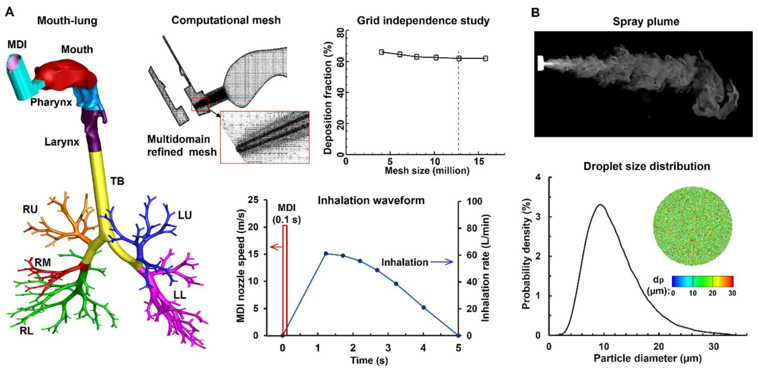
42]. This lung model extended from the trachea through the ninth bifurcation generation (G9), incorporating 512 bronchiolar outlets. To simulate an upright posture, the trachea was angled 15° forward. SolidWorks was used to develop the MDI model, which had a nozzle diameter of 0.4 mm. This MDI geometry was seamlessly connected to the oral cavity through a mouthpiece
Figure 1A, right lower panel). The near-nozzle region was modeled using an ultrafine mesh to capture the highly transient evaporation process and the droplet interactions with the local flow, temperature, and humidity.
2.2. Experimental Methods
To evaluate the exit velocity of spray droplets, the temporospatial evolution of the spray plume was recorded using a high-speed camera (Phantom VEO) at 1,200 fps. To enhance the contrast between the aerosol cloud and the surrounding air, a laser sheet (OXlaser, 488 nm, 100 mW) was used. PIVLab was used to estimate the exiting speed of the spray droplets by analyzing the motions of multiple droplets in consecutive frames, which was found to be around 20 m/s.
To measure the inhaler output per application, the inhaler was fired five times consecutively and its mass reduction was weighed each time using a high-precision electronic scale (Bonvoisin, San Jose, CA, USA). The average mass per application was 17.0±1.6 mg.
To evaluate the size distribution of the droplets, the sprays were measured immediately downstream of the nozzle using a laser diffraction particle size analyzer (Spraylink, Dickinson, TX, USA). For the tested inhaler, the spray had a D3: 6.848 µm, D10: 9.068 µm, D50: 16.322 µm, D90: 27.723 µm, and D97: 34.544 µm, with a distribution as shown in
Figure 1B. The measured spray droplet size distribution, as well as the droplet exiting speed and spray mass per administration, was subsequently used as the inlet and/or initial conditions for the computational simulations.
2.3. Numerical Methods
2.3.1. Boundary Conditions and Computational Mesh
The flow was assumed to be incompressible. There were two airflow sources: the jet flow from the MDI nozzle, present only during actuation, and the patient's inspiratory flow, which persisted throughout the delivery process. The MDI-jet flow followed a step-like profile lasting 0.1 s at 20 m/s (red line,
Figure 1A). In contrast, the inhaled airflow followed a deep, slow pattern typical of MDI use, entering the airway through the gap between the MDI holder and canister (blue line,
Figure 1A). The inhalation lasted 5 seconds, reaching a peak flow rate of 61.2 L/min at 1.23 seconds after the start of inhalation. Additionally, a 1-second breath-hold was simulated after the inhalation to ensure that all droplets either completed deposition or exited the airway. The environment had a temperature of 22
oC and 30% relative humidity (RH).
The spray was administered at the beginning of inhalation for 0.1 s (
Figure 1A) and the spray droplets size distribution followed the laser-diffraction measurements, as shown in
Figure 1B. The droplet injection file consisted of 25,000 droplets, and each parcel had a mass flow rate of 6.8 × 10
-9 kg/s, ensuring an administrated mass of 17 mg being released within 0.1 s. The initial temperature and RH of the spray droplets was 10
oC and 100%.
The airway wall was modeled as rigid and smooth, with no-slip conditions applied. The temperature and relative humidity on the airway wall were kept constant, matching average body conditions at 37°C and 99%, respectively. The inhaled components considered in this study included air, water vapor, and 1% saline droplets. The droplets had a density of 1.0 g/cm³ and were considered to deposit on the airway surface upon contact.
ANSYS Fluent 23 was employed to simulate respiratory airflows and droplet evaporation/transport/deposition. ANSYS ICEMCFD was used to generate the multidomain computational mesh with local refinement. A grid independence study was performed by testing multiple meshes with incremental refinements (from 4 to 16 million). The mesh-independent results for deposition were attained with a size of 12.6 million (
Figure 1A).
2.3.2. Thermos-Humidity Governing Equations for Moist Air
The inhalation and MDI-jet flows were resolved using the LES-WALE model [
43]. This method has been shown to accurately capture the transitions between laminar and turbulent flow regimes [
44,
45]. The heat and mass transfer equations governing the variation of air temperature (
T) and vapor concentration (
Yv) in the airway are [
46]:
In these two equations, Cp and κg are the specific heat and thermal conductivity of the air, respectively; Yv is the water vapor mass fraction, ScT is the turbulent Schmidt number (ScT = 0.9), PrT is the turbulent Prandtl number (PrT = 0.9), and is the binary diffusion coefficient of water vapor in the air. The enthalpy of the moist air is hs. In the mass transport equation, thermal energy transport due to diffusion was omitted, as the Lewis numbers for both air and water vapor were close to one. For the two species considered, the mass fraction of air was determined to be Ya = 1.0 - Yv.
The relative humidity of the moist air is determined by the local temperature and local vapor pressure. This local relative humidity affects the evaporation and condensation of water vapor on droplet surfaces. The relative humidity (RH) of the moist air is represented as:
Here,
Rv represents the gas constant of water vapor and
ρm denotes the mixture density. The saturation pressure of the water vapor
Pv,sat is calculated using the Antoine equation [
47]. The mass flux of water vapor at the wall is influenced by the local RH value. If the near-wall RH is below 1, evaporation from the surface is assumed. When the near-wall RH exceeds 1, condensation occurs on the wall surface.
2.3.3. Droplet Evaporation and Condensation Model
Under rapid mixing model (RMM) conditions, the governing equations for energy and mass conservation for a droplet are [
48]:
Here,
md is the droplet mass,
nv is the mass flux of the evaporating water vapor at the droplet surface,
Cpd is the composite liquid specific heat,
qconv is the convective heat flux, and
Lv is the water latent heat. The vapor concentration on the droplet surface can be modeled following Raoult’s law [
49],
where
Xw is the mole fraction of the water based on soluble components. In this study, the inhaled droplets consist of water and 1% salt. Following Eqn 6, the vapor pressure on the droplet surface is lowered by approximately 1%. The effect of droplet size on the vapor concentration at the droplet surface, i.e., Kelvin effect, is:
Here, σ(Td) is the surface tension of the water, which is a function of local temperature.
2.3.4. Droplet Transport Model
The discrete phase Lagrangian tracking model was used to simulate the transport and deposition of evaporating droplets:
Here, α is the air-droplet density ratio,
vi is the droplet velocity,
τp is the residence time of the droplet (
τp =
ρp dp2/18
μ) [
50]. The drag coefficient
f is calculated following Morsi and Alexander [
51]. The Cunningham correction factor
Cc was computed following Allen and Raabe [
52], and λ is the mean free path of the air [
50].
2.4. Deposition Quantification
2.4.1. Deposition Fraction
Note that polydisperse aerosols were administered from the MDI nozzle. Thus, the deposited droplets were also polydisperse, no matter if evaporation was considered or not. Accordingly, there were three methods to quantify the deposition fraction, i.e., based on the droplet count, droplet mass, or the drug carried by the droplets. For an evaporating droplet, the solvent (water) evaporates but the solute (salt) does not. Thus, the evaporation process of a droplet will change its size, mass, and trajectory, but not the non-volatile solute that it carries. Assuming that there are
N droplets depositing in a given region, the deposition fraction (DF) can be quantified as follows:
Here d0 is the initial droplet size, dFinal is the final droplet size, and C is the drug concentration, which can be canceled out in Eqn. 10c. Quantifying the drug-based DF requires two steps: (1) find the IDs of each deposited particles, and (2) use these ID to find the initial mass of these deposited droplets, which gives the deposited drug mass by multiplying the drug concentration. A user-defined function (UDF) was developed to identify the deposited droplet IDs and retrieve their initial droplet sizes for drug-based DF calculation.
2.4.2. Deposition Enhancement Factor (DEF)
Local dosimetry, termed as deposition enhancement factor (DEF), was assessed as the ratio of the normalized DF on a 0.5-mm-diameter area over the averaged DF [
53]. Like DF, there are three methods to calculate the DEF value in the region
i: count-based, mass-based, and drug-based,
3. Results
3.1. Model Validation
3.1.1. Free Fall of 10-µm Water Droplet
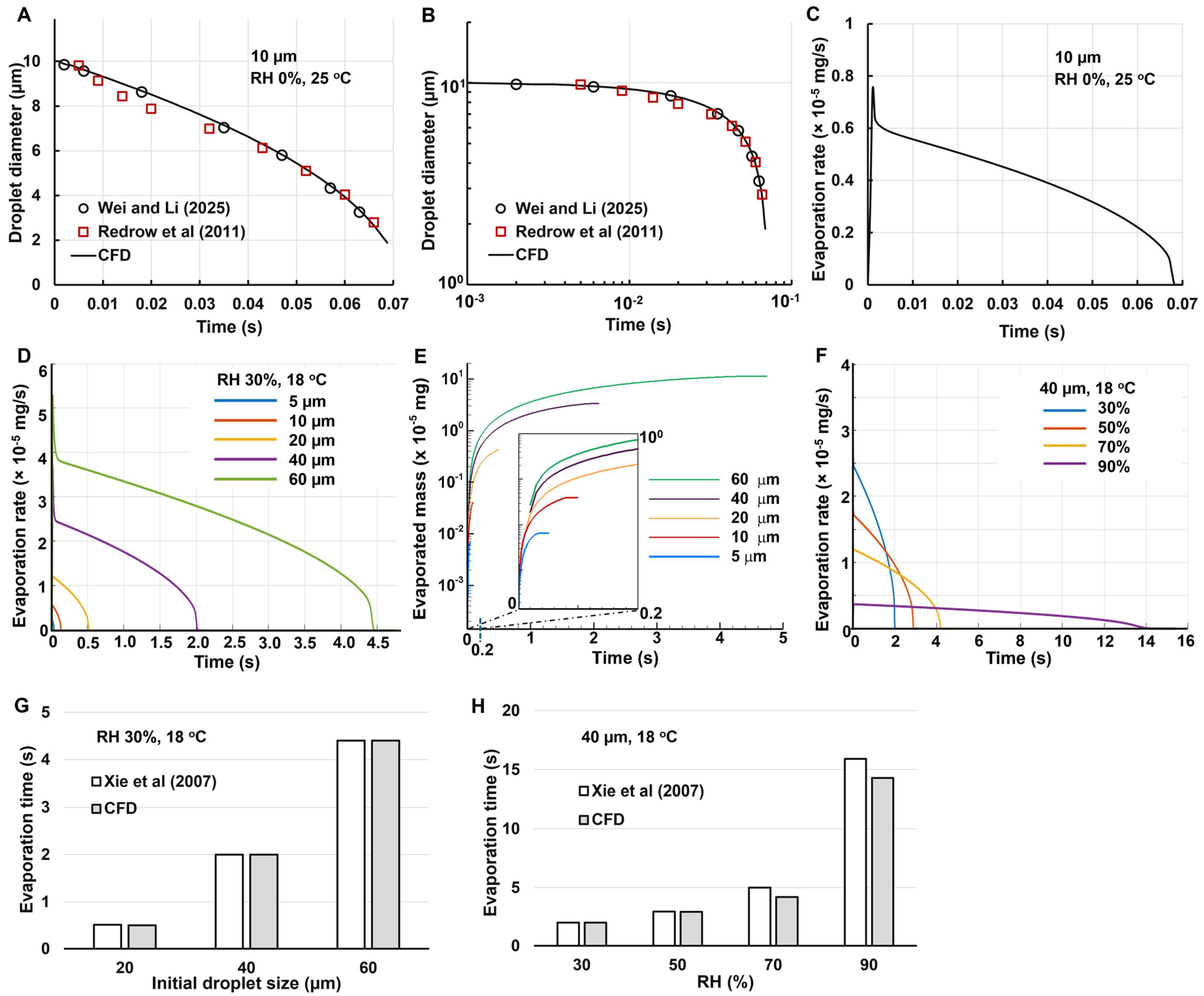
Figure 2A shows the CFD-predicted droplet size variation in comparison to the Wei and Li [
54] and Redrow et al (ref) at arithmetic scales. The initial droplet size is 10 µm, which fall freely in still air with 0% RH and 25
oC. A good agreement was achieved in this case, indicating that the computational model in this study captured the evaporation mechanisms. Following Li et al. [
55], the same figure was also replotted in
Figure 2B at log-log scales, which also exhibited a high degree of match between the model in this study and the other studies [
54,
56].
Figure 2C shows the evaporate rate of one droplet with an initial dimeter of 10 µm as a function of time. The evaporation rate reaches the peak immediately upon exposure to a dry environment (0% RH), and then gradually decreases, with a faster-than-linear rate. This is because the surface area per unit mass increases as the droplet becomes smaller. It is also noted that the area under the curve (i.e., the integration of evaporation rate with time) is close to the mass of a 10-µm water droplet (i.e., 5.236 × 10⁻
7 mg), indicating that nearly all water content has evaporated.
3.1.2. Effect of Droplet Size and Relative Humidity
Figure 2D shows the effect of the initial size on the droplet evaporation rate. The droplet sizes considered include 5, 10, 20, 40, and 60 µm. As expected, the peak evaporation rate is higher for larger droplets. It is also observed that the peak evaporation rate is approximately linear with the diameter (1.216 × 10⁻
5 mg for 20 µm and 2.591 × 10⁻
5 mg for 40 µm), while the evaporation time is roughly proportional to the diameter squared (e.g., 0.5 s for 20 µm and 2.1 s for 40 µm). As such, the area under the curve is proportional to the diameter cubed, consistent with the droplet volume or mass.
The cumulative evaporated mass is shown in
Figure 2E. Considering the large difference in mass between the droplet of 5 µm and 20 µm, the semi-log cale was adopted in the y-axis. Similarly, due to the even larger variation in evaporation time, a zoomed-out inset showing t = 0–0.2 s was also presented in
Figure 2F, showing the complete evaporation process for small droplets (5 and 10 µm,
Figure 2E).
The effect of relative humidity (RH) on the evaporation rate of a 40-µm droplet is shown in
Figure 2F. The RH considered ranges from 30% to 90%. The evaporation rate is observed to be very sensitive to local relative humidity. It takes 2 s for a 40-µm droplet to complete evaporation at 30% RH, but it will take 14 s at 90% RH (
Figure 2F). As a result, the spray droplets may experience large variations in the upper airway during and shortly after spray administration. Cool and dry air is inhaled into the mouth during spray administration, which then interacts with the warm humid air in the airway, leading to a highly heterogeneous temperature distribution in the upper airway. Good agreement in the evaporation time was obtained between CFD predictions in this study and the theoretical results by Xie et al. [
57], as shown in Figs. 2G and 2H.
3.2. Droplet Evaporation in Respiratory Tract
3.2.1. Temporospatial Thermo-Humidity Dynamics
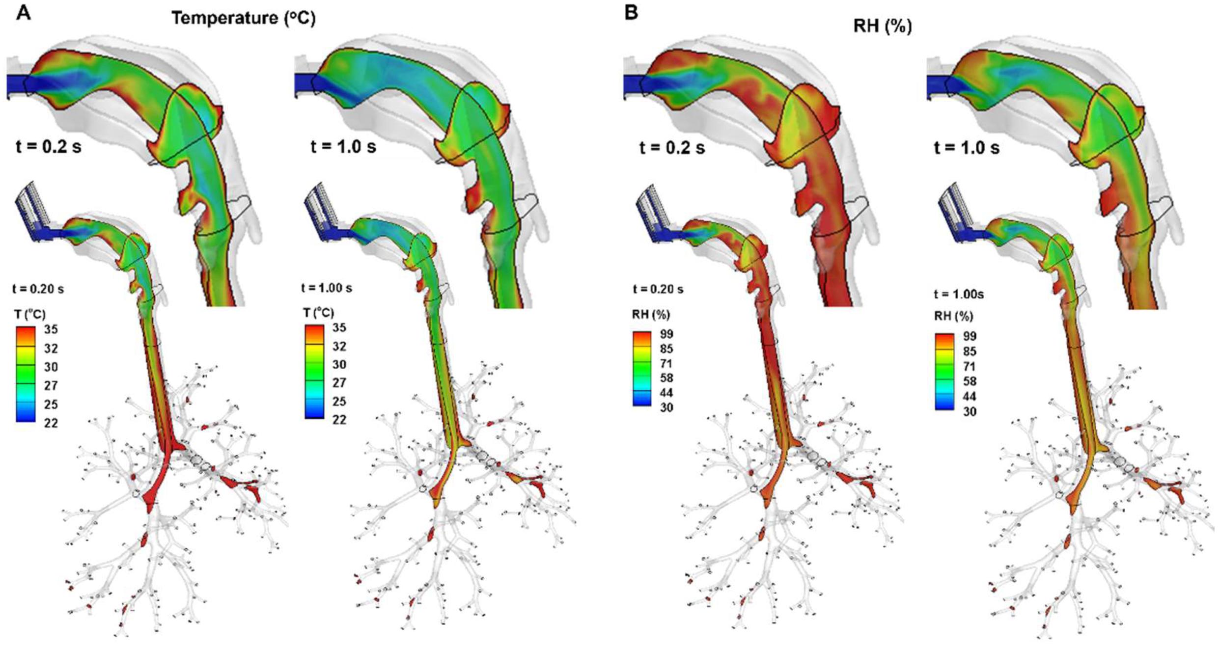
As shown in
Figure 3, the inhalation of cool, dry ambient air (20
oC, 30% RH), as well as the cooler spray flow (10
oC) generates a temperature field that is colder and drier than body conditions (37
oC and 99% RH). The warming and humidifying effects from the airway tissue take time to bring the inhaled air closer to body conditions. On the other hand, the increasing flow rate during inhalation prolongs the time needed for the airway tissue to warm and humidify the air, as demonstrated by the more extended colder and drier areas (green color) from 0.2 s to 1.0 s.
3.2.2. Droplet Dynamics
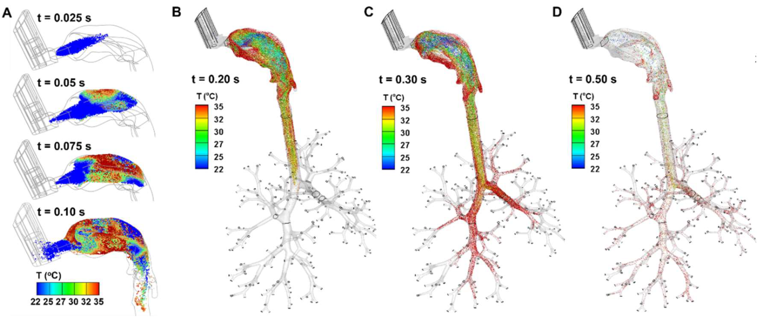
The instantaneous droplet dynamics are shown in
Figure 4, during 0.025–0.5 s after being administered from the MDI into the mouth. All droplets have a temperature of 10
oC upon release (t = 0 s) at the MDI nozzle. Their location, temperature, and evaporation-induced size variation were tracked thenceforth. Note that the temperature scale adopted here ranges from 22
oC (room temperature) to 35
oC. Thus, the spray plume at 0.025 s is still below 22
oC (blue color,
Figure 4A). At 0.05 s, some droplets warm to above 22
oC, and even some close to the roof of the mouth approach 35
oC. The droplet temperature increases quickly between 0.05 s and 0.10 s (
Figure 4A); at the same time, the droplets evaporate, shrink in size, and deposit onto the walls of the MDI and airways.
From
Figure 4B, the spray plume reached the carina ridge of the trachea at 0.2 s. The temperature of the droplets is the highest on the two lateral sides of the mouth, while that near the roof and back of the mouth is the lowest. The former was because of the low speeds of the droplets, allowing sufficient time for heat transfer, and the latter was because of their fast motion, as well as convection-enhanced evaporation, which was consistent with the cold sensation often experienced during MDI application. The temperature of the droplets in the trachea fell between them, with a mix of droplets of temperature ranging 30-35
oC.
At 0.3 s (
Figure 4C), the droplets advanced to the seventh or eighth generations (G7/G8) of the lung. One notable difference between Figs. 4B and 4C is the close-to-body temperature of the droplets in the lung in
Figure 4C. Both the smaller flow speeds and smaller droplet sizes contribute to this uniformity, allowing sufficient time for these more responsive droplets to adapt to the local temperature.
At 0.5 s (
Figure 4D), it is observed that most of the inhaled droplets have been deposited, leaving a very small faction of droplets lingering within the entire mouth-lung airway. These droplets would gradually deposit, taking another 0.6–1.0 s to complete deposition (figures not shown).
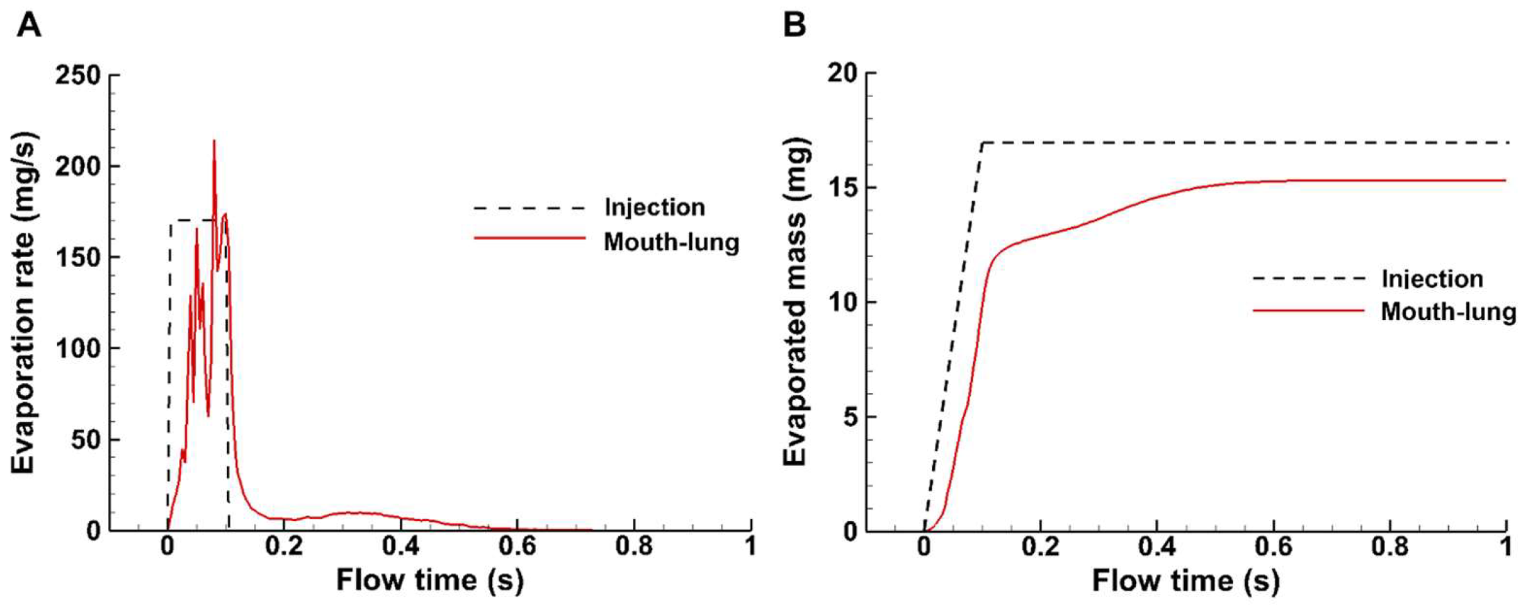
3.2.3. Spray Evaporation Rate and Evaporated Mass
In this study, the total injected dose was 17 mg and was administered within 0.1 s, which was based on the measurement with an in-house MDI and was shown by the dashed step profile in
Figure 5A. The instantaneous evaporation rate increases with the administrated dose and decreases after the completion of spray administration, which lasts another 0.5 s (0.1–0.6 s) until becoming unnoticeable (
Figure 5A). The cumulative evaporated mass is shown in
Figure 5B (red solid line), in comparison to the administrated spray mass (dashed black line). It is noted that the spray aerosol evaporates around 70% of the applied mass by the end of administration (0.1 s). Evaporation continues thereafter, but at a much lower rate. However, at 1 s, there is still 10% of the mass remaining, which reaches an equilibrium.
3.3. Droplet Deposistion Visulization
3.3.1. Surface Deposition with and without Evaporation
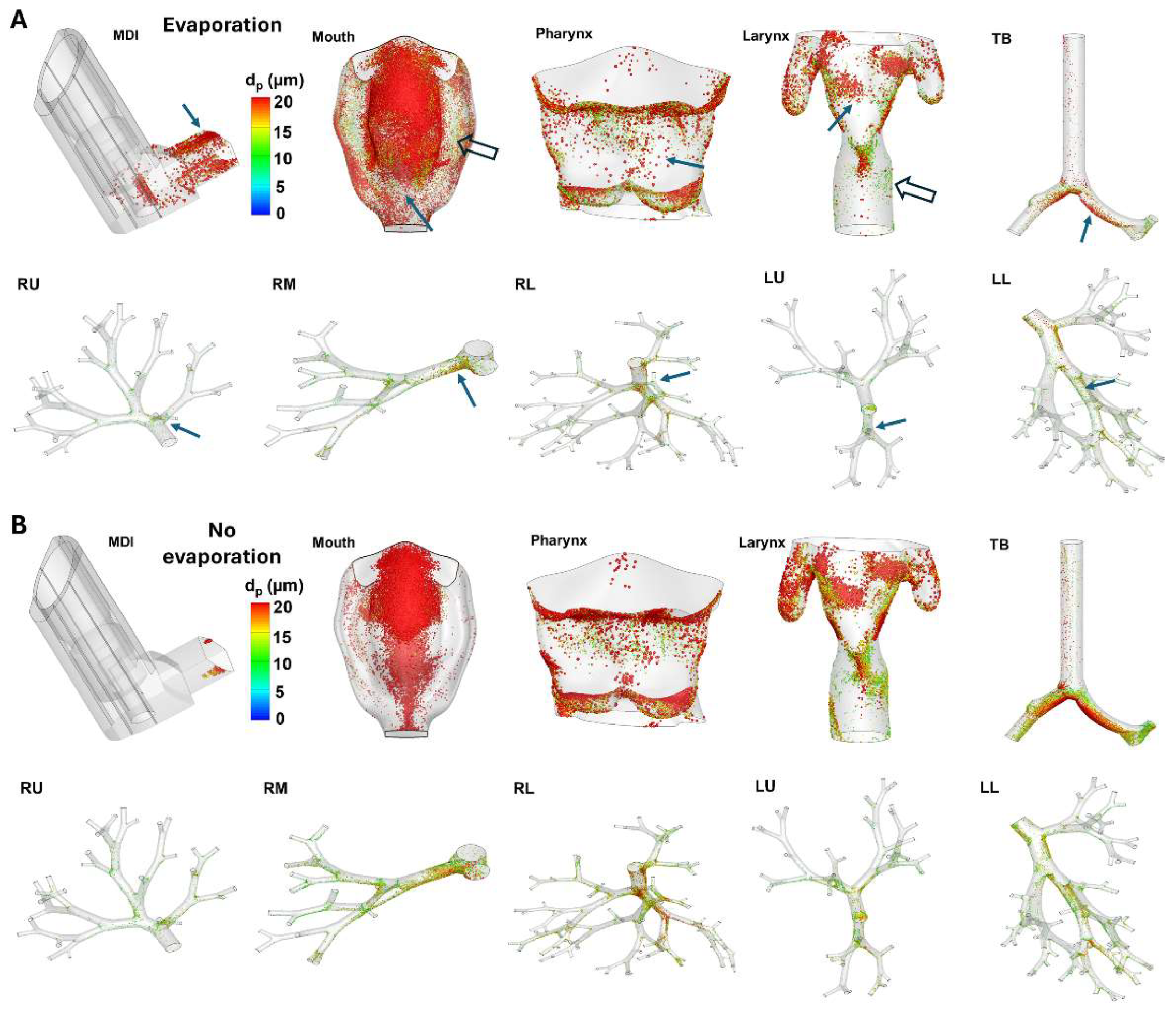
Figure 6A shows the surface deposition of MDI spray droplets with evaporation in different regions. Considering the varying sizes of different regions and the inevitable blockage of certain regions at any given direction, the surface deposition was shown individually for each region at its best possible orientation.
Significant discrepancies were noted in deposition distribution with and without evaporation (Figs. 6A vs. 6B), especially in the MDI and mouth-throat regions. Firstly, evaporation not only deposited more droplets in the MDI, but also elicited a more dispersive pattern, indicating an elevated mixing between flows (nozzle jet and inspiration) and evaporating droplets. By contrast, the MDI deposition in the absence of evaporation appeared more regular and its wedge-shaped profile could be attributed to the cone-shaped spray plume within the MDI mouthpiece (
Figure 6B). Similar observations were also noted in the mouth (second panel, Figs. 6A vs. 6B). In contrast to the more focused deposition without evaporation, including evaporation led to more dispersed deposition. Thus, fewer droplets deposited in the front of the mouth (solid arrow, second panel,
Figure 6A). Droplets also entered the narrow spaces between the tongue and the lateral side (hollow arrow, second panel,
Figure 6A), which was absent when evaporation was excluded.
More dispersed deposition profiles were also found in the pharynx and larynx (third and fourth panels), but with less significant levels. Considering the lung, which includes the tracheobronchial (TB) region and five lobes, evaporation led to less global deposition, as well as less local accumulation at the bifurcations (Figs. 6A vs, 6B); this was presumably attributed to the enhanced depletion of droplets in the upstream mouth-throat region.
3.3.2. Deposition Enhancement Factor (DEF)
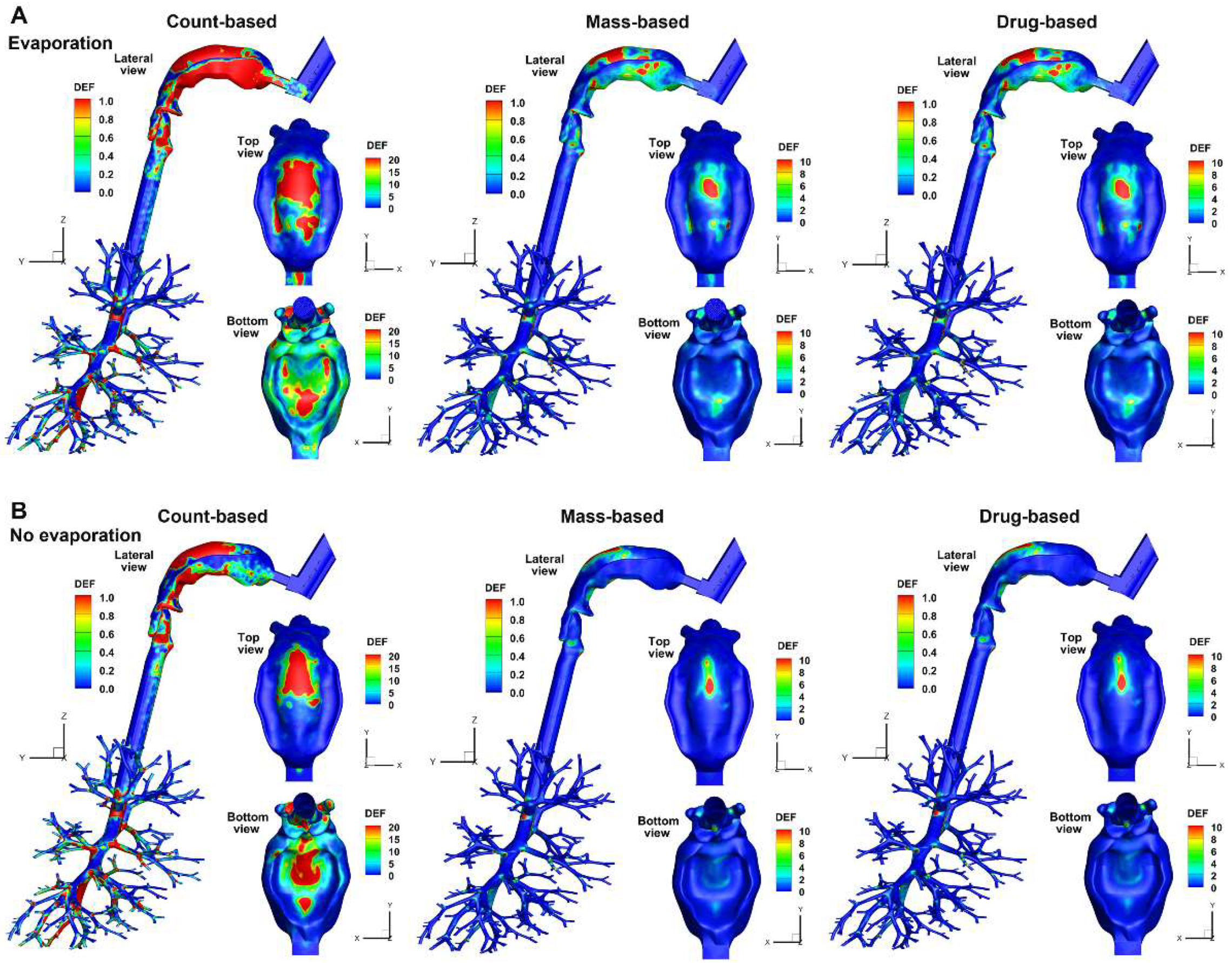
When plotted on the same scale, the DEF exhibit notably different patterns with vs. without evaporation, regardless of the quantification method used. Evaporation caused more dispersive patterns in the mouth, as demonstrated by the larger areas/content of hot spots in the mouth roof (top view) and the tongue (bottom view) in
Figure 7A.
Considering the effect of quantification methods, very different patterns were observed between the count-based DEF and the mass-/drug-based ones, with the count-based DEF having larger magnitudes than those of the other two methods. The lower magnitudes of the mass-based or drug-based DEF in the mouth-throat region are due to the high deposition rate in this region, compared to which all other regions have lower DF, leading to lower DEF values. The DEF patterns appear similar (but not identical) between the mass-based and drug-based methods in the mouth-throat region (Figs. 7A and 7B). This is because the deposition rate, when calculated using these two methods, is close in magnitude in the mouth-throat region. Note that the mass-based and drug-based DEF values can be very different in the lower airways, but due to the non-planar, cascade-bifurcating architecture, visualizing these differences is not straightforward. Quantitative comparisons of local or regional droplet accumulation are needed, as will be presented in the following section.
3.4. Quantifciation of Regional Deposistion
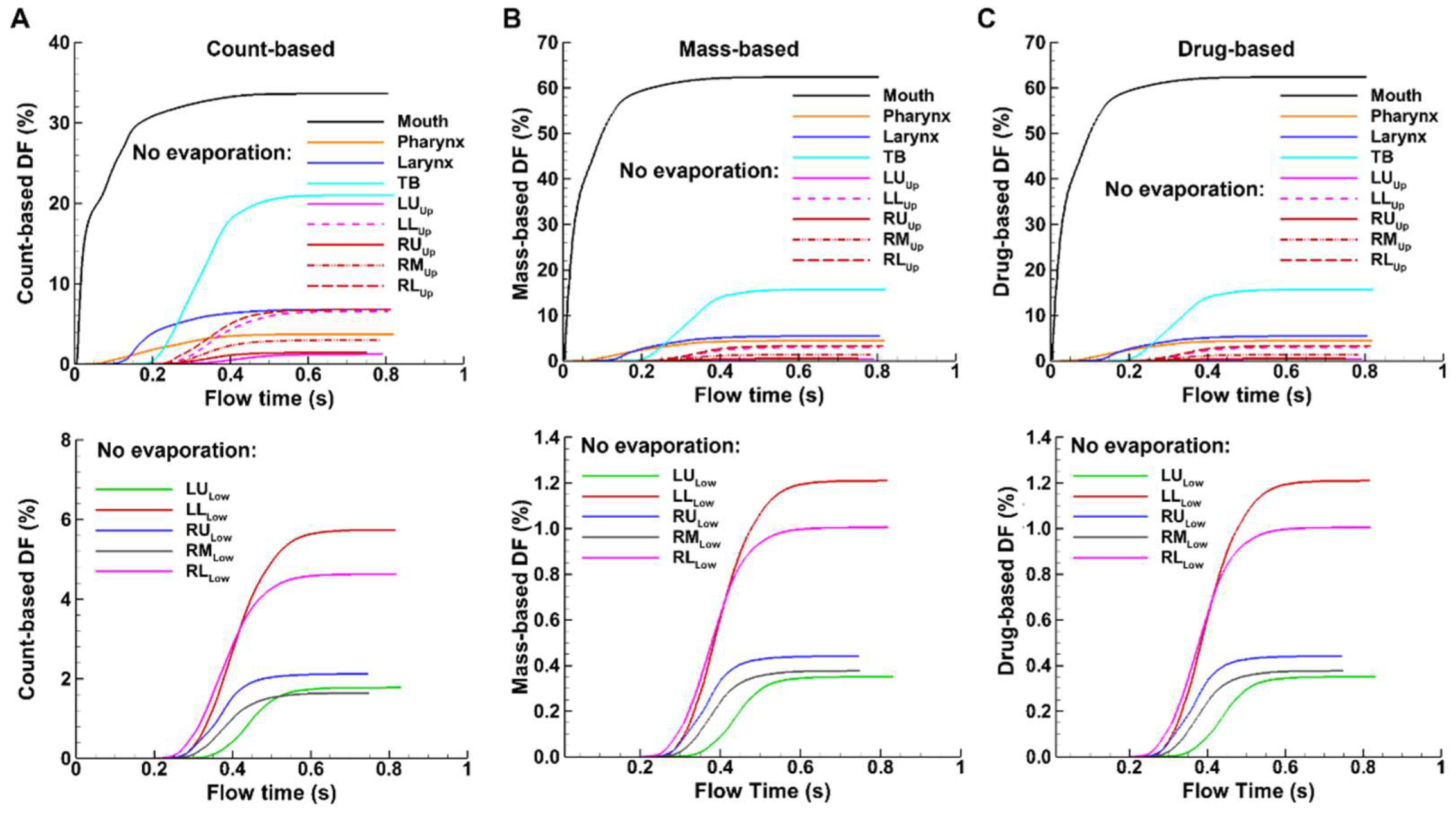
3.4.1. Temporal Variation of DF (Deposition Fraction)
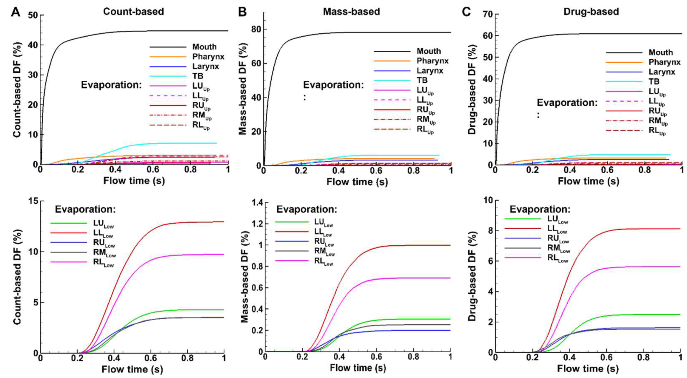
Figure 8 shows the temporal variation of deposition fraction (DF) after spray administration based on the count, mass, and carried drug of applied sprays, with evaporating droplets in
Figure 8A and non-evaporating droplets in
Figure 8B. Different scales on the y-axis have been used for the three quantitative methods so that, for a given method, the regional DFs can be best compared among themselves. For instance, the y-axis maximal value is 50% for the count-based (
Figure 8A), 84% for the mass-based (
Figure 8B), and 70% for the drug-based (
Figure 8C).
Significant fractions of administered spray droplets deposit in the mouth, regardless of the DF quantification method (black solid line, Figs. 8A–C). However, the count-based DF is the lowest (44.7%), the mass-based DF is the highest (78.1%), and the drug-based DF falls in between (56.5%). This is reasonable because the droplets depositing in the mouth are mostly large in size, and thus have larger masses (proportional to diameter cubed), leading to much a higher mass-based DF value than the count-based DF in this region. The drug-based DF in the mouth is lower than the mass-based counterpart. This is because evaporation is not yet complete, and the droplets in the mouth possess a higher water-to-drug ratio than those in the downstream respiratory tract, where evaporation continually depletes water.
Temporally, deposition in the mouth starts immediately after administration (
Figure 9). Deposition starts sequentially in the downstream airways, i.e., about 0.05 s in the larynx, 0.17 s in the TB region, 0.19 s in the conducting lung (G2-G10), and 0.23 s in the small airways (G11 and beyond). In comparison to evaporating droplets, similar patterns of DF variations, but with different magnitudes, are observed for non-evaporating (or inert) particles (Figs. 8 vs. 9). which will be examined further in the following sections. Moreover, for non-evaporating droplets, the mass-based and drug-based DFs are identical, as shown in Figs. 9B and 9C, due to the same drug concentration in the spray solution before administration.
3.4.2. Regional DF vs. Dosimetry Methods
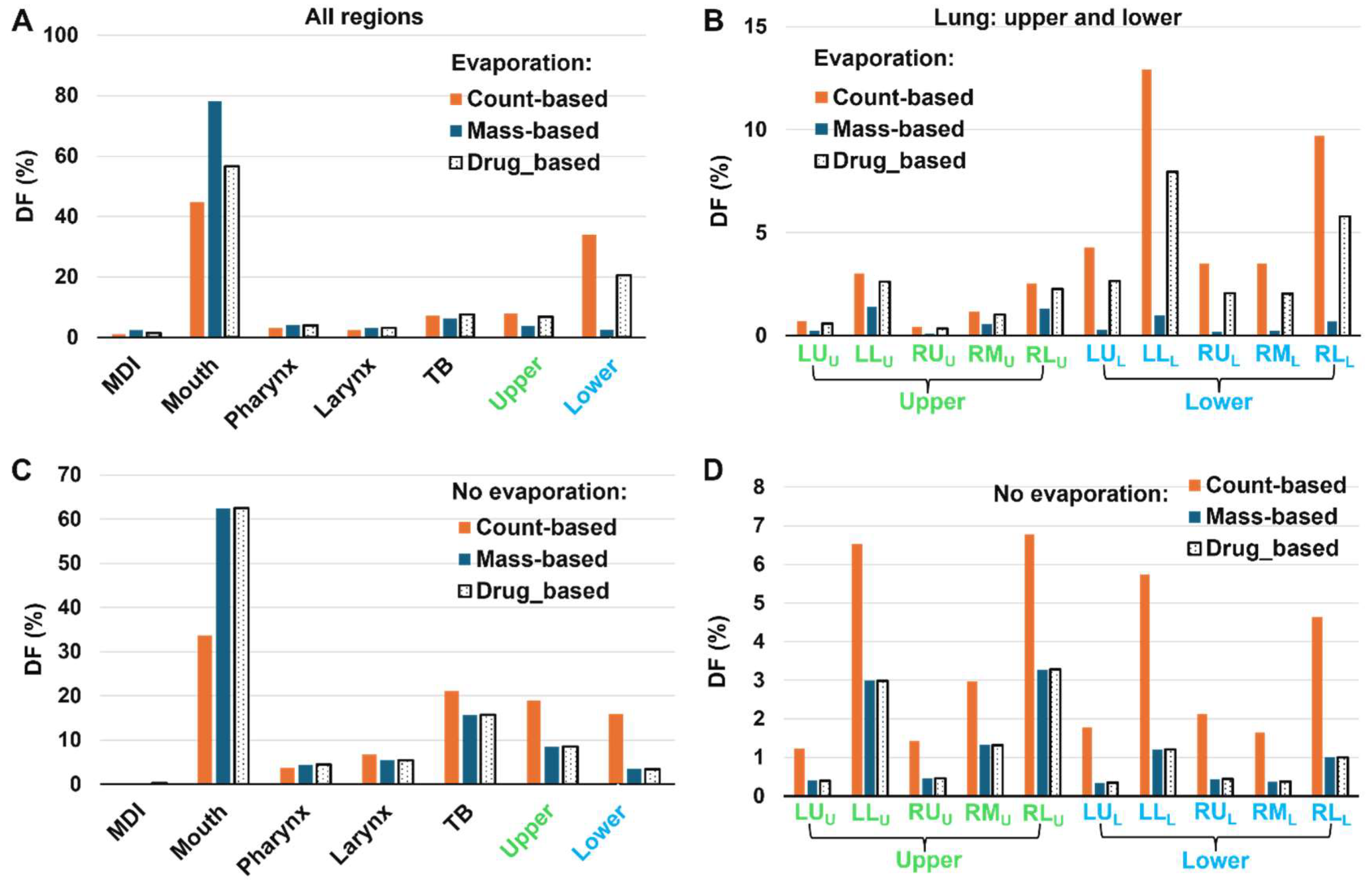
To assess the effect of dosimetry methods (i.e., count-, mass-, and drug-based) on the MDI spray delivery efficiency, the three DF values are compared side by side in
Figure 10.
Again, for evaporating droplets deposited in the mouth, the count-based DF is the lowest (44.7%), followed by the drug-based (56.5%, or 26% relatively higher, from [56.5%-44.7%]/44.7% = 26%) and the mass-based (78.1%, or 75% relatively higher). An ascending trend is also observed in the pharynx and larynx, but with a diminishing discrepancy.
The trend reserves to be descending in the upper and lower lungs, where the count-based DF is the highest while the mass-based DF is the lowest, characteristic of the deposition of smaller droplets from a polydisperse aerosol. Moreover, the level of discrepancy relative to the count-based DF increase drastically from the upper lung to the lower lung, indicating a significant increase in the deposition of even smaller droplets in the lower lung due to evaporation. Take the LL (left-lower) lobar DF as an example. In the upper lung, the count-, mass-, and drug-based DF is 3.0%, 1.4%, and 2.6%, respectively (
Figure 10B); relative to the count-based DF, the mass-based DF decreases by 53% and the drug-based decreases by 13%. By comparison, in the lower lung, the count-, mass-, and drug-based DF is 12.9%, 1.0%, 7.9%, respectively (
Figure 10B), representing a decrease of 92% for the mass-based DF and 46% for the drug-based DF. This increasing level of discrepancy in small airways highlights the need to use the appropriate methodology to quantify and report the delivery efficiency of inhalers with evaporating droplets.
Considering the non-evaporating droplets, the mass- and drug-based DFs are identical, as noted in Figure9. Furthermore, evaporation results in notable variations in the deposition across all regions considered.
3.4.3. DFMass/DFCount
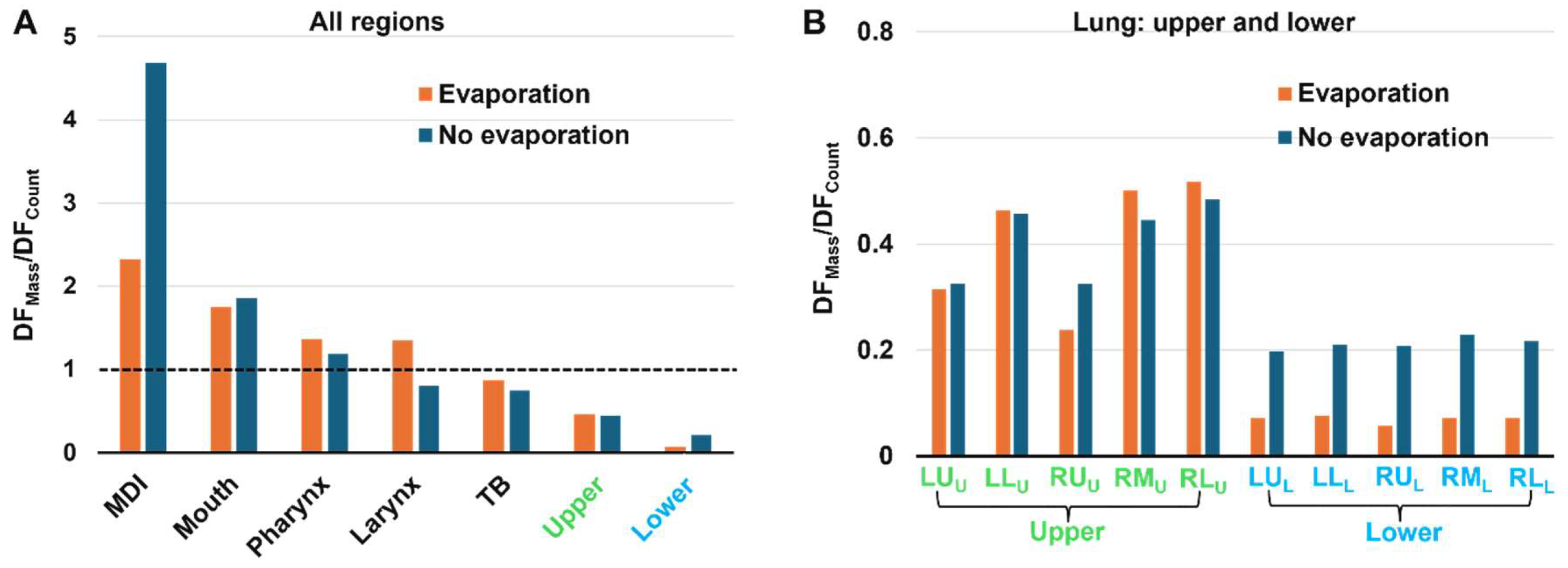
To further evaluate the evaporation-induced variations in deposition, the ratio of mass-based DF to count-based DF (i.e., DF
Mass/DF
Count) was calculated for each region for both evaporating and non-evaporating droplets. A large value of DF
Mass/DF
Count indicates that more large droplets are deposited; conversely, a small value of DF
Mass/DF
Count indicates that predominately smaller droplets deposit in this region. In
Figure 11A, it is observed that the DF
Mass/DF
Count value progressively decreases along the respiratory tract, consistent with the fact that larger droplets deposit in the larger airway, leaving smaller droplets to deposit in the lower airways. The DF
Mass/DF
Count value begins to fall below one in the TB region, indicating that the deposited droplet diameter is less than the mean size.
In
Figure 11A, the lower DF
Mass/DF
Count value in the mouth for evaporating droplets than inert particles reflect the rapid evaporation and size shrinking during spray releasing. On the other hand, in the five lobes of the lower lung, the DF
Mass/DF
Count values with evaporation are much smaller than those without evaporation (
Figure 11B), indicating that evaporation exerts a significant impact on the doses delivered to the deep lungs.
3.4.4. Size Distribution of Deposited Droplets
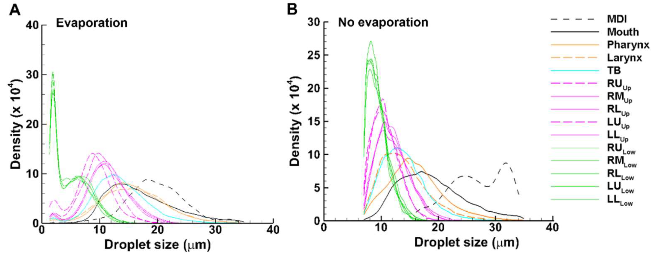
Different colors were used for different groups of airways: black for MDI and mouth, brown for pharynx and larynx, cyan for TB, pink for the five lung lobes with G2-G11 (dashed for lower lobes: RL and LL), and green for the five lobes beyond G11 (
Figure 12). For both cases, droplets deposited in the MDI have the largest average size, followed by, in descending order, the mouth, pharynx, larynx, TB, the five lobes in the upper lung, and the five lobes in the lower lung (Figs. 12A and 12B). Differences are also apparent between these two cases, with the average droplet size in each region being smaller with evaporation than without. The size distribution of the droplets in the MDI without evaporation is bi-modal with peaks at 24 µm and 32 µm, respectively, while those with evaporation are mono-modal, with the peak at 18 µm (
Figure 12). This may partially explain the concentrated deposition pattern for inert particles vs. the dispersed pattern for evaporating droplets, as shown earlier in
Figure 6 (surface deposition) and
Figure 7 (DEF).
Another difference is the size distribution of droplets that escape the mouth-lung region and enter the lower lung (green lines). In comparison to the peak value of 8 µm for inert particles (without evaporation), the evaporating droplets exhibit a bi-modal profile, with the first peak at 2 µm and the second peak at 6 µm. Moreover, the wider and higher size distribution profile of the evaporating droplets is consistent with the enhanced doses in the deep lungs, as presented in
Figure 10B.
4. Discussion
The integration of evaporation dynamics with deposition modeling offers insights into the behavior and fate of an evaporating droplet, the factors influencing its behavior, and how these factors affect the assessment of MDI performance, as discussed below.
4.1. Evaporation Effects
In this study, experimentally determined spray properties of an MDI were used as the initial/boundary conditions, including the applied mass of 17 mg per actuation. We noticed that evaporation occurs in the oropharyngeal airway quickly upon administration (
Figure 5), with 70% of the applied mass being evaporated at the end of administration (0.1 s). Evaporation continues thereafter at a much lower rate and remains 10% after 1 s, reaching an equilibrium. These observations are consistent with
Figure 3, where both the temperature and relative humidity (RH) in the oropharyngeal region are non-equilibrium, whereas they become equilibrium in the lung. The inhaled airflow is cooler (22
oC) and drier (30% RH) than the body condition, creating a region amendable for the high-speed, cold (10
oC), and saturated spray droplets to evaporate (
Figure 3). Both the inhaled air and injected droplets gradually warm up due to heat exchange with the airway tissue, as demonstrated by the instantaneous temperature transition of the droplets during the administration (0–0.1 s). At 0.3 s, the droplets reach the lung (
Figure 4C). Their temperature also reaches the body condition. Thus, an equilibrium between the droplets and airflow is attained, deterring further evaporation.
Spray droplet evaporation in the oropharyngeal region significantly alters the behavior and fate of these droplets. In Figs. 6 and 7, we observed very different patterns in surface deposition and deposition enhancement factor (DEF) between cases with and without evaporation. While the most visually apparent difference is noted in the mouth, significant differences also occur in the lower lung, which often is the primary target of MDI delivery. As shown in Figs. 9 and 10, the drug-based deposition fraction (DF) was 20.5% with evaporation, in comparison to 3.4% without evaporation. This is because evaporation significantly reduces the droplet size, shifting more droplets to the range of 1–5 µm and thus increasing the fine particle fraction (FPF). By contrast, the drug-based DF in the mouth is 56.5% with evaporation, only slightly lower than that without evaporation (62.5%, Fig 10).
Also note that the final droplet size distribution in the lower lung exhibits a bimodal shape for evaporating droplets, with the primary peak around 2 µm and the second peak 6.5 µm (green lines,
Figure 12A). Instead, a monomodal profile is observed for inert particles, with the peak around 7.5 µm (green lines in 12B). The proximity of the large droplet peaks between evaporating droplets and inert particles indicates that these droplets are from the same monomodal distribution that has not yet fully evaporated. A similar observation has been reported by Stein [
24], who experimentally measured the MDI droplet sizes in a cascade impactor that was preceded by either the U.S. Pharmacopeial induction port (USP) or a large chamber. Stein [
24] reported a bimodal profile after the USP but a monomodal profile after the large chamber, leading to the speculation that large droplet modes in the two cases were from the same original monomodal distribution, only that these large droplets escaped the USP filtration and meanwhile did not fully evaporate. Stein [
24] also emphasized that the MDI droplet size distribution changed substantially during the measurement process, which was sensitive to the degree of evaporation before measurement, rendering it highly challenging to accurately characterize the evaporation process.
The observation that evaporation increased the fine particle fraction (1–5 µm), thus enhancing peripheral doses, has favorable implications in MDI delivery. By carefully selecting propellant and solvent, formulations can be designed with specific evaporation profiles tailored to target specific regions of the lung. For instance, Hindle and Longest leveraged the enhanced condensation growth to reduce drug losses in the mouth-throat region and increase the retention in the small airways [
58]. Similarly, Saleem and Smyth utilized cosolvents and surfactants to tune MDI aerosol size distribution to the desired range [
59].
4.2. Dosimetry Methods: Count-, Mass-, Drug-Based
The results of this study demonstrate that the deposition fraction (DF) magnitude can be highly sensitive to the dosimetry method (count-based, mass-based, or drug-based). In the lower lung, the count-based DF (33.9%) and mass-based DF (2.4%) deferred by more than one order of magnitude, while the drug-based DF fell between them (20.5%), as shown in
Figure 9. The DF sensitivity to dosimetry method is lower in the upper lung, with the DF being 7.8% count-based, 3.6% mass-based, and 6.8% drug-based for evaporating droplets (
Figure 9A). Because the droplets deposited in the lungs are the smallest of the aerosol, their count-based DF is always higher than the mass-based DF in these regions (due to lower mass per droplet count).
Also, the DF sensitivity to the dosimetry method depends on the region of interest. The DF difference among the three methods is the lowest in the tracheobronchial (TB) region, but starts to increase in the larynx, pharynx, and mouth. This is because larger droplets deposit in the upper airway and smaller droplets deposit in the small airways, with average-sized droplets depositing in the TB region, as depicted by the regional size distributions in
Figure 12.
Collectively, we observed high DF sensitivity to the dosimetry method in the two ends: the oropharyngeal region (wasted dose) and the peripheral airways (effective dose). This highlights the need to use the appropriate method to quantify the delivery efficiency of evaporating droplets. Previous predictive dosimetry studies often adopted a monodisperse aerosol and calculated the DF as the ratio of the number of deposited particles over the number of administered particles, as shown in Eqn. 10a. This practice, however, is only valid when the aerosol has a very narrow range and is non-evaporating [
33]. If the aerosol consists of volatile components or is hygroscopic in nature, the subsequent mass change of the aerosol particles due to evaporation or condensation will change not only their trajectories and deposition sites but also the drug concentrations within them. For MDI formulations, which have initially homogeneous concentrations of nonvolatile drugs within volatile solvents, evaporation needs to be considered to accurately capture the droplets deposited in the pulmonary region, and the drug-based method should be used to report the deposited doses.
5. Conclusions
A computational model was developed and validated that integrated aerosol evaporation dynamics and mouth-lung dosimetry. Experimentally determined spray speed, mass, and size distribution of an MDI were implemented as the initial/boundary conditions. Specific findings were listed below:
Evaporation occurs quickly upon administration, with 70% of applied mass being evaporated at the end of administration (0.1 s).
The value of regional deposition fraction (DF) is highly sensitive to the dosimetry methods (count-based, mass-based, or drug-based).
The mass-based over count-based DF ratio in the lower lung was 0.07 for evaporating droplets and 0.21 for inert particles. By contrast, the ratio in the MDI was 2.3 for evaporating droplets and 4.7 for inert particles.
Compared to the non-evaporation case, the drug-based DF with evaporation slightly decreased (from 62.5% to 56.5%) in the mouth but significantly increased (from 3.4% to 20.5%) in the lower lung.
Evaporation significantly shifted the droplet size distribution in the lower lung lobes from a monomodal profile to a bimodal profile.
Droplet evaporation and drug-based DF are recommended for numerical assessment of MDI performance in pulmonary drug delivery.
Author Contributions
Conceptualization, M.T., X.S. and J.X.; methodology, M.T., X.S., and J.X.; validation, M.T., X.S., and J.X.; formal analysis, M.T., X.S., and J.X.; investigation, M.T., and J.X.; resources, X.S. and J.X.; data curation, J.X.; writing—original draft preparation, J.X.; writing—review and editing, M.T., X.S.; All authors have read and agreed to the published version of the manuscript.
Funding
Please add: This research received no external funding.
Data Availability Statement
The data presented in this study are available on request from the corresponding author.
Acknowledgments
We thank Amr Seifelnasr for helpful discussions and editing of this manuscript.
Conflicts of Interest
The authors declare no conflict of interest.
References
- Brocklebank, D.; Wright, J.; Cates, C. Systematic review of clinical effectiveness of pressurised metered dose inhalers versus other hand held inhaler devices for delivering corticosteroids in asthma. BMJ 2001, 323, 896–900. [Google Scholar] [CrossRef]
- Stein, S.W.; Sheth, P.; Hodson, P.D.; Myrdal, P.B. Advances in metered dose inhaler technology: hardware development. AAPS PharmSciTech 2014, 15, 326–338. [Google Scholar] [CrossRef]
- Liljelind, I.; Norberg, C.; Egelrud, L.; Westberg, H.; Eriksson, K.; Nylander-French, L.A. Dermal and inhalation exposure to Methylene Bisphenyl Isocyanate (MDI) in iron foundry workers. Ann. Occup. Hyg. 2009, 54, 31–40. [Google Scholar]
- Wrench, W.; Van Dyk, L.; Srinivas, S.; Dowse, R. Outcome of illustrated information leaflet on correct usage of asthma-metered dose inhaler. Afr J Prim Health Care Fam Med 2019, 11, e1–e9. [Google Scholar] [CrossRef]
- A, S.; Haward, R.; Chakraborty, A. Evaluation of the Metered Dose Inhaler technique: Initial assessment and post-counseling improvements among the indian population. Cureus 2024, 16, e57397. [Google Scholar] [CrossRef]
- Cho-Reyes, S.; Celli, B.R.; Dembek, C.; Yeh, K.; Navaie, M. Inhalation technique errors with Metered-Dose Inhalers among patients with obstructive lung diseases: A systematic review and Meta-analysis of U.S. studies. Chronic. Obstr. Pulm. Dis. 2019, 6, 267–280. [Google Scholar] [CrossRef]
- Biswas, R.; Hanania, N.A.; Sabharwal, A. Factors determining In vitro lung deposition of Albuterol aerosol delivered by Ventolin Metered-Dose Inhaler. J. Aerosol Med. Pulm. Drug Deliv. 2017, 30, 256–266. [Google Scholar] [CrossRef]
- Dolovich, M. Measurement of particle size characteristics of metered dose inhaler (MDI) aerosols. J. Aerosol Med. 1991, 4, 251–263. [Google Scholar] [CrossRef]
- Walenga, R.L.; Longest, P.W. Current inhalers deliver very small doses to the lower tracheobronchial airways: Assessment of healthy and constricted lungs. J. Pharm. Sci. 2016, 105, 147–159. [Google Scholar] [CrossRef]
- Xi, J.; Zhao, W. Correlating exhaled aerosol images to small airway obstructive diseases: A study with dynamic mode decomposition and machine learning. PloS One 2019, 14, e0211413. [Google Scholar] [CrossRef]
- Mitchell, J.P.; Nagel, M.W. Time-of-flight aerodynamic particle size analyzers: their use and limitations for the evaluation of medical aerosols. J. Aerosol Med. 1999, 12, 217–240. [Google Scholar] [CrossRef]
- Mitchell, J.P.; Nagel, M.W.; Wiersema, K.J.; Doyle, C.C. Aerodynamic particle size analysis of aerosols from pressurized metered-dose inhalers: comparison of Andersen 8-stage cascade impactor, next generation pharmaceutical impactor, and model 3321 Aerodynamic Particle Sizer aerosol spectrometer. AAPS PharmSciTech 2003, 4, E54. [Google Scholar] [CrossRef]
- Liu, X.; Doub, W.H.; Guo, C. Evaluation of metered dose inhaler spray velocities using Phase Doppler Anemometry (PDA). Int. J. Pharm. 2012, 423, 235–239. [Google Scholar] [CrossRef]
- Martin, A.R.; Kwok, D.Y.; Finlay, W.H. Investigating the evaporation of metered-dose inhaler formulations in humid air: single droplet experiments. J. Aerosol Med. 2005, 18, 218–224. [Google Scholar] [CrossRef]
- Legh-Land, V.; Haddrell, A.E.; Lewis, D.; Murnane, D.; Reid, J.P. Water uptake by evaporating pMDI aerosol prior to inhalation affects both regional and total deposition in the respiratory system. Pharmaceutics 2021, 13, 941. [Google Scholar] [CrossRef]
- Sheth, P.; Grimes, M.R.; Stein, S.W.; Myrdal, P.B. Impact of droplet evaporation rate on resulting in vitro performance parameters of pressurized metered dose inhalers. Int. J. Pharm. 2017, 528, 360–371. [Google Scholar] [CrossRef]
- Shemirani, F.M.; Hoe, S.; Lewis, D.; Church, T.; Vehring, R.; Finlay, W.H. In vitro investigation of the effect of ambient humidity on regional delivered dose with solution and suspension MDIs. J. Aerosol Med. Pulm. Drug Deliv. 2013, 26, 215–222. [Google Scholar] [CrossRef]
- Ivey, J.W.; Bhambri, P.; Church, T.K.; Lewis, D.A.; McDermott, M.T.; Elbayomy, S.; Finlay, W.H.; Vehring, R. Humidity affects the morphology of particles emitted from beclomethasone dipropionate pressurized metered dose inhalers. Int. J. Pharm. 2017, 520, 207–215. [Google Scholar] [CrossRef]
- Rostamnezhad, M.; Jafari, H.; Moradikhah, F.; Bahrainian, S.; Faghihi, H.; Khalvati, R.; Bafkary, R.; Vatanara, A. Spray freeze-drying for inhalation application: process and formulation variables. Pharm. Dev. Technol. 2022, 27, 251–267. [Google Scholar] [CrossRef]
- Fan, K.; Zhang, M.; Mujumdar, A.S. Recent developments in high efficient freeze-drying of fruits and vegetables assisted by microwave: A review. Crit. Rev. Food Sci. Nutr. 2019, 59, 1357–1366. [Google Scholar] [CrossRef]
- Hsein, H.; Auffray, J.; Noel, T.; Tchoreloff, P. Recent advances and persistent challenges in the design of freeze-drying process for monoclonal antibodies. Pharm. Dev. Technol. 2022, 27, 942–955. [Google Scholar] [CrossRef]
- Massei, A.; Fissore, D. A new model-based approach for the development of freeze-drying cycles using a small-scale freeze-dryer. J Pharm Sci 2023, 112, 2176–2189. [Google Scholar] [CrossRef]
- Carfagna, M.; Rosa, M.; Hawe, A.; Frieß, W. Design of freeze-drying cycles: The determination of heat transfer coefficient by using heat flux sensor and MicroFD. Int. J. Pharm. 2022, 621, 121763. [Google Scholar] [CrossRef]
- Stein, S.W. Aiming for a moving target: challenges with impactor measurements of MDI aerosols. Int. J. Pharm. 2008, 355, 53–61. [Google Scholar] [CrossRef]
- Lewis, D.A.; Young, P.M.; Buttini, F.; Church, T.; Colombo, P.; Forbes, B.; Haghi, M.; Johnson, R.; O'Shea, H.; Salama, R.; et al. Towards the bioequivalence of pressurised metered dose inhalers 1: design and characterisation of aerodynamically equivalent beclomethasone dipropionate inhalers with and without glycerol as a non-volatile excipient. Eur. J. Pharm. Biopharm. 2014, 86, 31–37. [Google Scholar] [CrossRef]
- Fröhlich, E. Biological obstacles for identifying In vitro-In vivo correlations of orally inhaled formulations. Pharmaceutics 2019, 11. [Google Scholar] [CrossRef]
- Darquenne, C.; Fleming, J.S.; Katz, I.; Martin, A.R.; Schroeter, J.; Usmani, O.S.; Venegas, J.; Schmid, O. Bridging the gap between science and clinical efficacy: Physiology, imaging, and modeling of aerosols in the lung. J. Aerosol Med. Pulm. Drug Deliv. 2016, 29, 107–126. [Google Scholar] [CrossRef]
- Byron, P.R.; Hindle, M.; Lange, C.F.; Longest, P.W.; McRobbie, D.; Oldham, M.J.; Olsson, B.; Thiel, C.G.; Wachtel, H.; Finlay, W.H. In vivo-in vitro correlations: predicting pulmonary drug deposition from pharmaceutical aerosols. J. Aerosol Med. Pulm. Drug Deliv. 2010, 23 Suppl 2, S59–69. [Google Scholar] [CrossRef]
- Longest, P.W.; Kleinstreuer, C. Computational models for simulating multicomponent aerosol evaporation in the upper respiratory airways. Aerosol Sci. Tech. 2005, 39, 124–138. [Google Scholar] [CrossRef]
- Worth Longest, P.; Hindle, M. Numerical model to characterize the size increase of combination drug and hygroscopic excipient nanoparticle aerosols. Aerosol Sci. Tech. 2011, 45, 884–899. [Google Scholar] [CrossRef]
- Longest, P.W.; Tian, G.; Walenga, R.L.; Hindle, M. Comparing MDI and DPI aerosol deposition using in vitro experiments and a new stochastic individual path (SIP) model of the conducting airways. Pharm. Res. 2012, 29, 1670–1688. [Google Scholar] [CrossRef]
- Zanutto, C.P.; Paladino, E.E.; Nazareth, T.C. Heating and evaporation of ethanol/iso-octane droplets considering non-ideal mixtures and finite rate transfer. Fuel 2019, 256, 115811. [Google Scholar] [CrossRef]
- Talaat, M.; Si, X.; Liu, X.; Xi, J. Count- and mass-based dosimetry of MDI spray droplets with polydisperse and monodisperse size distributions. Int. J. Pharm. 2022, 623, 121920. [Google Scholar] [CrossRef]
- Zhou, M.; Zou, J. A dynamical overview of droplets in the transmission of respiratory infectious diseases. Phys. Fluids 2021, 33, 031301. [Google Scholar] [CrossRef]
- Günay, A.A.; Kim, M.-K.; Yan, X.; Miljkovic, N.; Sett, S. Droplet evaporation dynamics on microstructured biphilic, hydrophobic, and smooth surfaces. Exp. Fluids 2021, 62, 153. [Google Scholar] [CrossRef]
- Wang, Z.; Orejon, D.; Takata, Y.; Sefiane, K. Wetting and evaporation of multicomponent droplets. Phys. Rep. 2022, 960, 1–37. [Google Scholar] [CrossRef]
- Talaat, M.; Si, X.; Xi, J. Effect of MDI actuation timing on inhalation dosimetry in a human respiratory tract model. Pharmaceuticals 2022, 15, 61. [Google Scholar] [CrossRef]
- Cheng, Y.S.; Zhou, Y.; Chen, B.T. Particle deposition in a cast of human oral airways. Aerosol Sci. Tech. 1999, 31, 286–300. [Google Scholar] [CrossRef]
- Xi, J.; Kim, J.; Si, X.A.; Mckee, E.; Corley, R.A.; Kabilan, S.; Wang, S. CFD modeling and image analysis of exhaled aerosols due to a growing bronchial tumor: towards non-invasive diagnosis and treatment of respiratory obstructive diseases. Theranostics 2015, 5, 443–455. [Google Scholar] [CrossRef]
- Kitaoka, H. The origin of frequency dependence of respiratory resistance: An airflow simulation study using a 4D pulmonary lobule model. Respirology 2011, 16, 517–522. [Google Scholar] [CrossRef]
- Kitaoka, H.; Nieman, G.F.; Fujino, Y.; Carney, D.; DiRocco, J.; Kawase, I. A 4-dimensional model of the alveolar structure. J. Physiol. Sci. 2007, 57, 175–185. [Google Scholar] [CrossRef] [PubMed]
- Kitaoka, H.; Tamura, S.; Takaki, R. A three-dimensional model of the human pulmonary acinus. J. Appl. Physiol. 2000, 88, 2260–2268. [Google Scholar] [CrossRef] [PubMed]
- April Si, X.; Talaat, M.; Xi, J. SARS COV-2 virus-laden droplets coughed from deep lungs: Numerical quantification in a single-path whole respiratory tract geometry. Phys. Fluids 2021, 33. [Google Scholar] [CrossRef]
- Nicoud, F.; Ducros, F. Subgrid-scale stress modelling based on the square of the velocity gradient tensor. Flow Turbul. Combust. 1999, 62, 183–200. [Google Scholar] [CrossRef]
- Xi, J.; Wang, Z.; Talaat, K.; Glide-Hurst, C.; Dong, H. Numerical study of dynamic glottis and tidal breathing on respiratory sounds in a human upper airway model. Sleep Breath 2018, 22, 463–479. [Google Scholar] [CrossRef]
- Longest, P.W.; Xi, J. Condensational growth may contribute to the enhanced deposition of cigarette smoke particles in the upper respiratory tract. Aerosol Sci. Technol. 2008, 42, 579–602. [Google Scholar] [CrossRef]
- de la Calle-Arroyo, C.; López-Fidalgo, J.; Rodríguez-Aragón, L.J. Optimal designs for Antoine equation. Chemom. Intell. Lab. Syst. 2021, 214, 104334. [Google Scholar] [CrossRef]
- Longest, P.W.; Kleinstreuer, C. Computational models for simulating multicomponent aerosol evaporation in the upper respiratory airways. Aerosol Sci. Tech. 2005, 39, 124–138. [Google Scholar] [CrossRef]
- Atkins, P.; de Paula, J. Physical Chemistry, 8 ed.; Oxford University Press: 2006; p. 146.
- Hinds, W.C. Aerosol Technology: Properties, Behavior, and Measurement of Airborne Particles; John Wiley and Sons: New York, 1999. [Google Scholar]
- Morsi, S.A.; Alexander, A.J. An investigation of particle trajectories in two-phase flow systems. J. Fluid Mech. 1972, 55(2), 193–208. [Google Scholar] [CrossRef]
- Allen, M.D.; Raabe, O.G. Slip correction measurements of spherical solid aerosol particles in an improved Millikan apparatus. Aerosol Sci. Tech. 1985, 4, 269–286. [Google Scholar] [CrossRef]
- Xi, J.; Yuan, J.E.; Yang, M.; Si, X.; Zhou, Y.; Cheng, Y.-S. Parametric study on mouth–throat geometrical factors on deposition of orally inhaled aerosols. J. Aerosol Sci. 2016. [Google Scholar] [CrossRef]
- Wei, J.; Li, Y. Enhanced spread of expiratory droplets by turbulence in a cough jet. Build. Environ. 2015, 93, 86–96. [Google Scholar] [CrossRef]
- Li, X.; Shang, Y.; Yan, Y.; Yang, L.; Tu, J. Modelling of evaporation of cough droplets in inhomogeneous humidity fields using the multi-component Eulerian-Lagrangian approach. Build. Environ. 2018, 128, 68–76. [Google Scholar] [CrossRef]
- Redrow, J.; Mao, S.; Celik, I.; Posada, J.A.; Feng, Z.-g. Modeling the evaporation and dispersion of airborne sputum droplets expelled from a human cough. Build. Environ. 2011, 46, 2042–2051. [Google Scholar] [CrossRef]
- Xie, X.; Li, Y.; Chwang, A.T.Y.; Ho, P.L.; Seto, W.H. How far droplets can move in indoor environments – revisiting the Wells evaporation–falling curveAbstract. Indoor Air 2007, 17, 211–225. [Google Scholar] [CrossRef] [PubMed]
- Hindle, M.; Longest, P.W. Evaluation of enhanced condensational growth (ECG) for controlled respiratory drug delivery in a mouth-throat and upper tracheobronchial model. Pharm. Res. 2010, 27, 1800–1811. [Google Scholar] [CrossRef]
- Saleem, I.Y.; Smyth, H.D. Tuning aerosol particle size distribution of metered dose inhalers using cosolvents and surfactants. Biomed. Res. Int. 2013, 2013, 574310. [Google Scholar] [CrossRef]
Figure 1.
Computational model: (A) mouth-lung geometry, computational mesh, grid independent study, and inhalation waveform, (B) spray plume captured by high-speed camera and droplet size distribution measured using a particle size analyzer.
Figure 1.
Computational model: (A) mouth-lung geometry, computational mesh, grid independent study, and inhalation waveform, (B) spray plume captured by high-speed camera and droplet size distribution measured using a particle size analyzer.
Figure 2.
Model validation. A, B: droplet diameter variation vs. time for a free falling 10-µm droplet at 0% RH and 25 oC in comparison to literature at arithmetic scale and log-log scale; C: evaporation rate vs. time; D, E: effect of initial droplet size on evaporation rate and evaporated mass; F: effect of relative humidity, G, H: CFD-predicted evaporation time vs. literature for different droplet sizes and at different relative humidities.
Figure 3.
Thermo-humidity inside the airway at different instants (0.2 s and 1.0 s) after the start of inhalation: (A) temperature and (B) relative humidity (RH).
Figure 3.
Thermo-humidity inside the airway at different instants (0.2 s and 1.0 s) after the start of inhalation: (A) temperature and (B) relative humidity (RH).
Figure 4.
Spray droplet dynamics within the mouth-lung geometry at varying instants after inhalation: (A) 0.2 s, (B) 0.3 s, and (C) 0.5 s, with droplets colored by temperature.
Figure 4.
Spray droplet dynamics within the mouth-lung geometry at varying instants after inhalation: (A) 0.2 s, (B) 0.3 s, and (C) 0.5 s, with droplets colored by temperature.
Figure 5.
Evaporation rate (A) and evaporated mass (B) of applied MDT spray droplets into the mouth-lung geometry.
Figure 5.
Evaporation rate (A) and evaporated mass (B) of applied MDT spray droplets into the mouth-lung geometry.
Figure 6.
Comparison of surface deposition in the mouth-lung geometry: (A) with evaporation and (B) without evaporation, with arrows highlighting the disparities in various regions.
Figure 6.
Comparison of surface deposition in the mouth-lung geometry: (A) with evaporation and (B) without evaporation, with arrows highlighting the disparities in various regions.
Figure 7.
Comparison of DEF (deposition enhancement factor) with (A) and without (B) considering droplet evaporation quantified using count-, mass-, and drug-based methods.
Figure 7.
Comparison of DEF (deposition enhancement factor) with (A) and without (B) considering droplet evaporation quantified using count-, mass-, and drug-based methods.
Figure 8.
Regional deposition fraction (DF) vs. time for evaporating droplets based on different dosimetry methods: (A) count-based, (B) mass-based, and (C) drug-based.
Figure 8.
Regional deposition fraction (DF) vs. time for evaporating droplets based on different dosimetry methods: (A) count-based, (B) mass-based, and (C) drug-based.
Figure 9.
Regional deposition fraction (DF) vs. time for inert droplets based on different dosimetry methods: (A) count-based, (B) mass-based, and (C) drug-based.
Figure 9.
Regional deposition fraction (DF) vs. time for inert droplets based on different dosimetry methods: (A) count-based, (B) mass-based, and (C) drug-based.
Figure 10.
Comparison of DFs based on droplet count, mass, and contained drug. A, B: with evaporation, and C, D: without evaporation. A, C: all regions; B, D: upper and lower lungs.
Figure 10.
Comparison of DFs based on droplet count, mass, and contained drug. A, B: with evaporation, and C, D: without evaporation. A, C: all regions; B, D: upper and lower lungs.
Figure 11.
Comparison of DFMass/DFCount ratios with and without evaporation: (A) across all regions, and (B) in the upper and lower lobes of the lung.
Figure 11.
Comparison of DFMass/DFCount ratios with and without evaporation: (A) across all regions, and (B) in the upper and lower lobes of the lung.
Figure 12.
Droplet size distributions at different regions: (A) with evaporation, and (B) without evaporation.
Figure 12.
Droplet size distributions at different regions: (A) with evaporation, and (B) without evaporation.
|
Disclaimer/Publisher’s Note: The statements, opinions and data contained in all publications are solely those of the individual author(s) and contributor(s) and not of MDPI and/or the editor(s). MDPI and/or the editor(s) disclaim responsibility for any injury to people or property resulting from any ideas, methods, instructions or products referred to in the content. |
© 2024 by the authors. Licensee MDPI, Basel, Switzerland. This article is an open access article distributed under the terms and conditions of the Creative Commons Attribution (CC BY) license (http://creativecommons.org/licenses/by/4.0/).


