Submitted:
12 October 2024
Posted:
15 October 2024
You are already at the latest version
Abstract
Keywords:
1. Introduction
2. Methods
2.1. Live Laboratory Description


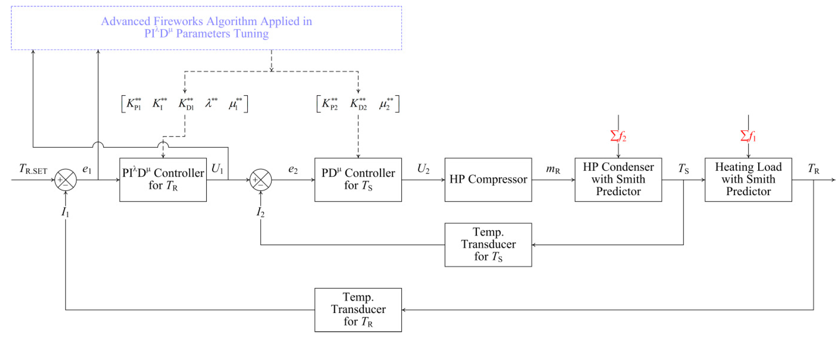
2.2. Advanced Control Strategy and Controller Design
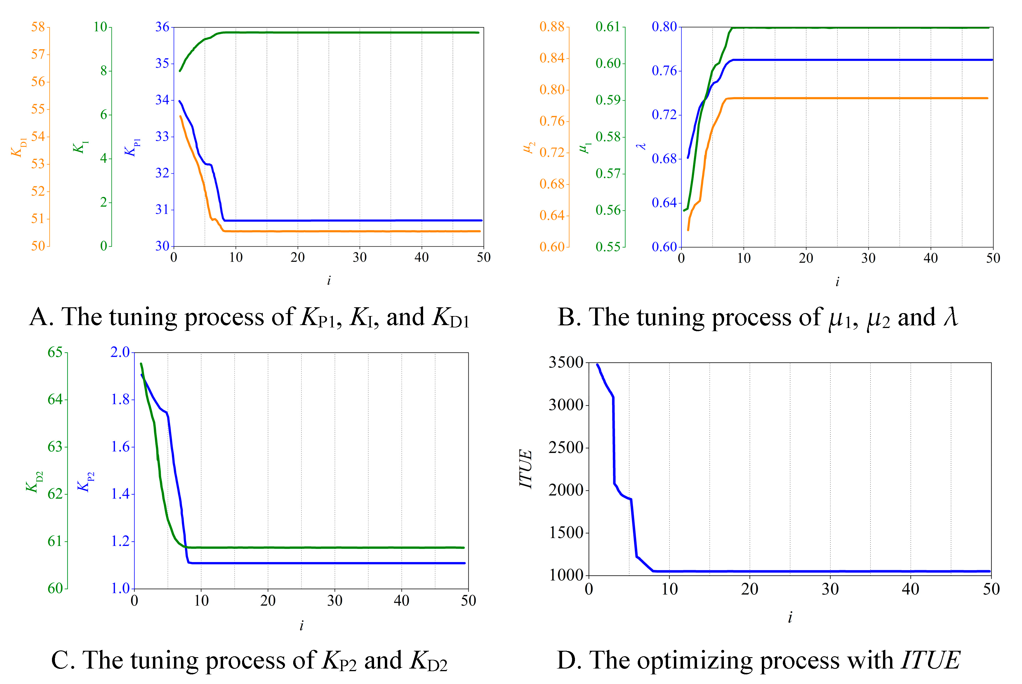
2.3. Advanced Adaptive Tuning Algorithm


2.4. Tuning Algorithm Tests
3. Results and Discussion
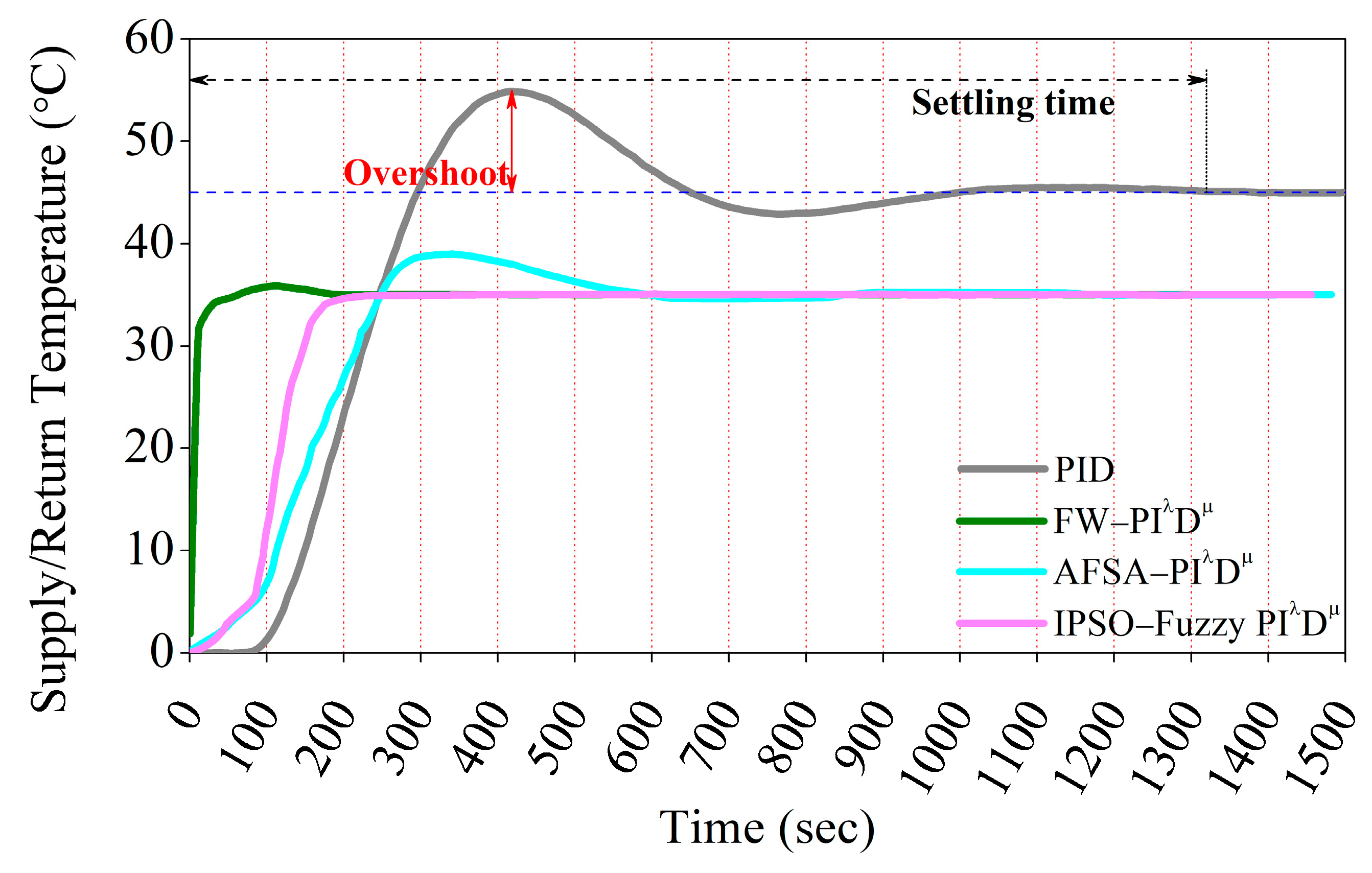
3.1. Simulation Test Results
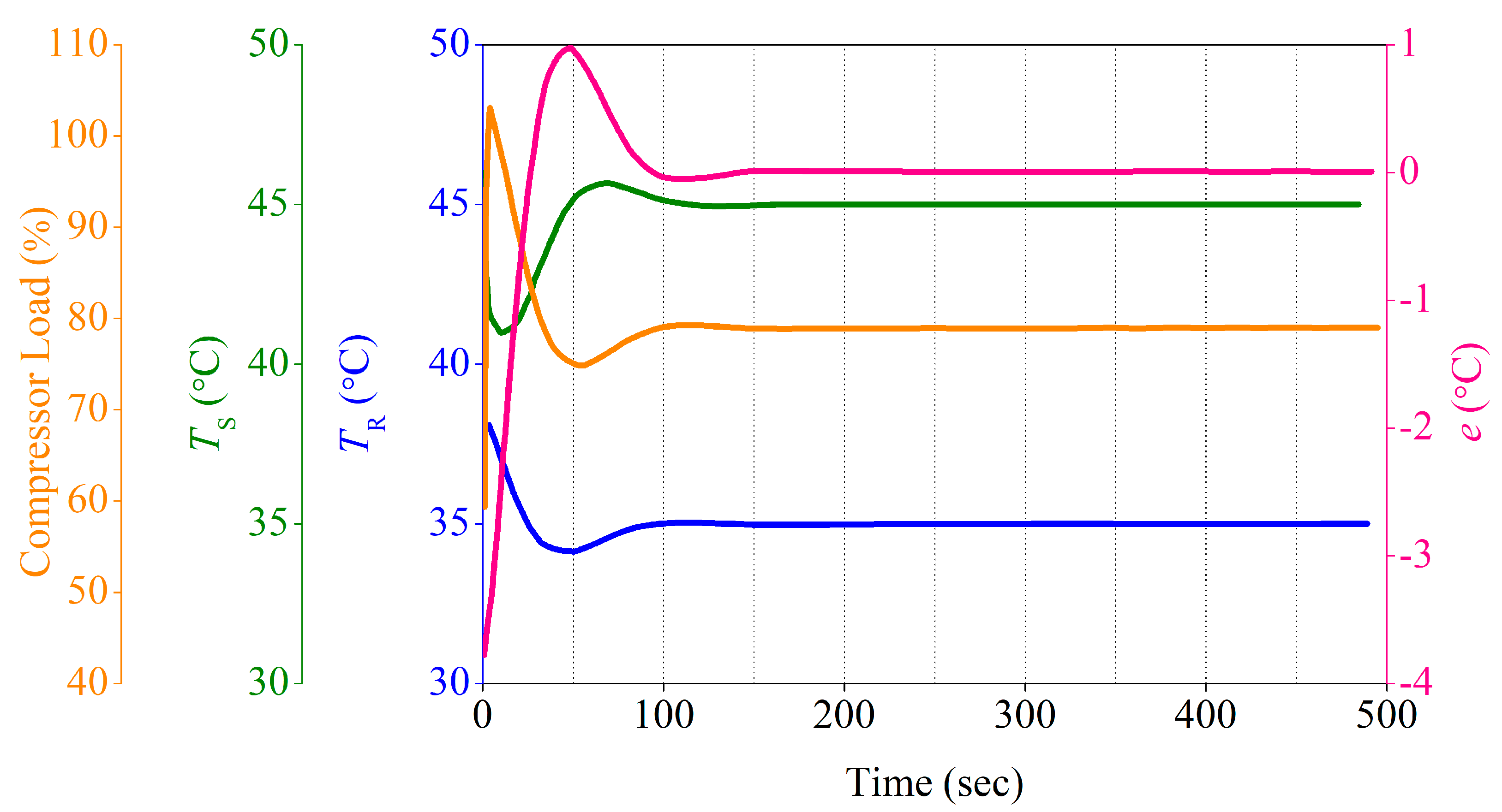
3.2. Live Measure
4. Conclusions
Author Contributions
Data Availability Statement
Acknowledgments
Conflicts of Interest
References
- National Development and Reform Commission, National Energy Administration, Ministry of Finance et al. Clean Heating Planning in winter in northern China (2017-2021). 2017. (In Chinese) https://www.gov.cn/xinwen/2017-12/20/content_5248855.htm/.
- Wu, J.; Song, L.; Wang, Z.; Sun, Y.; Wang, J. Implementation evaluation of clean heating pilot city in Northern China during the 13th Five-Year Plan period. Environmental Protection Science, 2023, 49: 48-55. (In Chinese). [CrossRef]
- Wang, Y.; Liu, W. Evaluating the effect of Clean Heating Policy Pilot on air quality improvement: A quasi-experimental study based on three batches of pilot cities in China. China Environmental Science, 2024, 44: 581-592. (In Chinese). [CrossRef]
- Zhai, Y.; Li, S. Summary research and prospect of clean heating renovation in northern rural areas of China. China Energy and Environmental Protection, 2023, 45: 194-200. (In Chinese). [CrossRef]
- Hou, L.; Ding, H.; Wang, S. Impact assessment of clean heating on carbon emission in rural residential building field. Building Science, 2022, 38: 260-265. (In Chinese). [CrossRef]
- Wen, Y.; Cao, Y.; Zhao, X.; Gao, W.; Lv, H. CiteSpace-based clean heating policy and technology development process and trend analysis. HV&AC, 2023, 53: 171-176. (In Chinese). [CrossRef]
- Song, L.; Wu, J.; Sun, Y.; Zhang, W. Research on the Renovation Technology and Subsidy Policy of Rural Clean Heating in the 14th Five-year Plan Period. Environmental Protection, 2022, 50: 15-20. (In Chinese). [CrossRef]
- Fu, B. Pay attention to building energy-saving renovation with the aim of promoting the sustainable development of clean heating in rural areas. Energy of China, 2023, 45: 82-90. (In Chinese) https://kns.cnki.net/kcms2/article/abstract?v=UeijT_GnegCbocwAfR1jEP_vTXXfG6cUXwuWe9bULk5Usf7TBNp8i_3i4-LF8hxMBN258GBLVOjHGnicqKI7WzyIU0f0LtJfmcj35gVbXdX70DEUDVCeJy6hSxo6PLh9h5r0CM1UwF0=&uniplatform=NZKPT&language=CHS/.
- Ministry of Housing and Urban-Rural Development of the People’s Republic of China. Technical Standard for Nearly Zero Energy Buildings (GB/T 51350-2019). 2019. (In Chinese) www.mohurd.gov.cn/.
- Chinese Society for Urban Studies. Evaluation Standard for Ultra-Low Energy Buildings (T/CSUS 15-2021). 2021. (In Chinese) http://www.chinasus.org/.
- Capone, M.; Guelpa, E.; Verda, V. Optimal installation of heat pumps in large district heating networks. Energies, 2023, 16: 1448. [CrossRef]
- Gong Y, Ma G, Jiang Y; et al. Research progress on the fifth-generation district heating system based on heat pump technology. Journal of Building Engineering, 2023, 71: 106533. [CrossRef]
- Pesola, A. Cost-optimization model to design and operate hybrid heating systems ? Case study of district heating system with decentralized heat pumps in Finland. Energy, 2023, 281: 128241. [CrossRef]
- Sayegh, M.A.; Jadwiszczak, P.; Axcell, B.P. Heat pump placement, connection and operational modes in European district heating. Energy & Buildings, 2018, 166: 122-144. [CrossRef]
- Kontu, K.; Rinne, S.; Junnila, S. Introducing modern heat pumps to existing district heating systems ? Global lessons from viable decarbonizing of district heating in Finland. Energy, 2019, 166: 862-870. [CrossRef]
- Dongellini, M.; Naldi, C.; Morini, G.L. Influence of sizing strategy and control rules on the energy saving potential of heat pump hybrid systems in a residential building. Energy Conversion and Management, 2021, 235: 114022. [CrossRef]
- Wei, Z.; Ren, F.; Yue, B. Data-driven application on the optimization of a heat pump system for district heating load supply: A validation based on onsite test. Energy Conversion and Management, 2022, 266: 115851. [CrossRef]
- Lashkari B, Chen Y, Musílek M; et al. Intelligent scheduling of heat pumps to minimize the cost of electricity. 2020 21st International Scientific Conference on Electric Power Engineering (EPE), Prague, Czech Republic, 2020, 1-6. [CrossRef]
- Yüce A, Deniz F N, Tan N; et al. Obtaining the time response of control systems with fractional order PID from frequency responses. 2015 9th International Conference on Electrical and Electronics Engineering (ELECO), Bursa, Turkey, 2015, 832-836. [CrossRef]
- Khodadadi, H.; Dehghani, A. Fuzzy logic self-tuning PID controller design based on Smith predictor for the heating system. 2016 16th International Conference on Control, Automation and Systems (ICCAS), Gyeongju, Korea (South), 2016, 161-166. [CrossRef]
- Dehghani, A.; Khodadadi, H. Designing a neuro-fuzzy PID controller based on Smith predictor for heating system. 2017 17th International Conference on Control, Automation and Systems (ICCAS), Jeju, Korea (South), 2017, 15-20. [CrossRef]
- Al-Dhaifallah, M. Heat Exchanger Control Using Fuzzy Fractional-Order PID. 2019 16th International Multi-Conference on Systems, Signals & Devices (SSD), Istanbul, Turkey, 2019, 73-77. [CrossRef]
- Yang, X.; Liu, T.; Sun, A. Auto-control of Water Condenser Based on PID Controller. AMR 2011, 225-226: 186-189. https://api.semanticscholar.org/CorpusID:111166572.
- Gao, L.; Yang, Y.; Ren, X.; Gu, H.; Han, Q.; Yu, J. Qingqing and Y. Jingya, Research on temperature control system based on IPSO optimized fuzzy PID. 2020 39th Chinese Control Conference (CCC), Shenyang, China, 2020, 2014-2019. [CrossRef]
- Wang, Y.; Liu, Y.; Zhu, R.; Zhang, Y. Fractional-order PID controller of a heating-furnace system. Advanced Materials Research, 2012, 490-495: 1145-1149. https://api.semanticscholar.org/CorpusID:122576625.
- Jiang A, Zhang Q, Wang H; et al. An improved dynamic real-time optimization strategy for heat pump heating system. CIESC Journal, 2019, 70: 1494-1504. (In Chinese). [CrossRef]
- Jiang P, Xu B, Li Q; et al. Buildings heat pump heating systems for demand response. District Heating, 2023: 100-111. (In Chinese). [CrossRef]
- Wang, C.; Liu, R. Modeling and simulation of a fuzzy PID controller for heat exchanger systems in district heating. Proceedings of the 2nd International Conference on Electronics, Network and Computer Engineering (ICENCE 2016), 699-703. [CrossRef]
- Al-Dhaifallah, M. Heat exchanger control using fuzzy fractional-order PID. 2019 16th International Multi-Conference on Systems, Signals & Devices (SSD), Istanbul, Turkey, 2019, 73-77. [CrossRef]
- Lu, Y.; Yang, Y.; Gu, H.; Zhang, Y. Identification and self-tuning control of heat pump system based on neural network. 2016 Chinese Control and Decision Conference (CCDC), Yinchuan, China, 2016, 6687-6691. [CrossRef]
- Abdullah, Z.; Othman, M.; Taip, F. Neural network based adaptive PID controller of nonlinear heat exchanger. 2019 IEEE 9th International Conference on System Engineering and Technology (ICSET), Shah Alam, Malaysia, 2019, 453-458. [CrossRef]
- Liu, X. Optimization design on fractional order PID controller based on adaptive particle swarm optimization algorithm. Nonlinear Dyn, 2016, 84: 379-386. [CrossRef]
- Tan, Y.; Zhu, Y. Fireworks Algorithm for Optimization. In: Tan Y, Shi Y, Tan K. (EDS) Advances in Swarm Intelligence. ICSI 2010. Lecture Notes in Computer Science, 6145. Springer, Berlin, Heidelberg. [CrossRef]
- Xue, J.; Wang, Y.; Li, H.; Meng, X.; Xiao, J. Advanced fireworks algorithm and its application research in PID parameters tuning. Mathematical Problems in Engineering, 2016, 2016, 2534632: 1-9. [CrossRef]
- Yin X, Li X, Liu L, Wang L, Improved fireworks algorithm and its application in PID parameters tuning. 2017 36th Chinese Control Conference (CCC), Dalian, China, 2017, 9841-9846. [CrossRef]
- Li, J.; Tan, Y. A comprehensive review of the fireworks algorithm. ACM Computing Surveys, 2019, 52: 1-28. [CrossRef]
- Zhang, G.; Li, F.; Geng, Y. Design of temperature control system for air heat pump water supply machine based on incremental PID control. Computer & Digital Engineering, 2021, 49: 268-271+321. (In Chinese). [CrossRef]
- Wei, Q. Design and research of the PID temperature controlling system based on air-source heat pump water supply unit. University of Chinese Academy of Sciences, 2017. (In Chinese) https://kns.cnki.net/kcms2/article/abstract?v=aKxFI3wG76hThvB4DmBe8HG0SNtTzn2s3MhayKfaKce0w4dGMrZTb1NcZCEXXCSvt_D7qHQpLz7xRHUuMwz8omJqLI25wtQRQouI8TQheA2fNPryZOUDmODt4Dp5y8U-GAgKZN6YSJSL08Ifh5KBKXlGbEQHhpJ-5Lgs5Uv-yhCRy98_atEEHVh-XITgBME-pUa0rUxNi4A=&uniplatform=NZKPT&language=CHS.
- Dongellini M, Valdiserri P, Naldi C; et al. The role of emitters, heat pump size, and building massive envelope elements on the seasonal energy performance of heat pump-based heating systems. Energies, 2020, 13: 5098. [CrossRef]
- Huang, H.; Zhang, S.; Yang, Z.; Tian, Y.; Zhao, X.; Yuan, Z.; Hao, S.; Leng, J.; Wei, Y. Modified Smith fuzzy PID temperature control in an oil-replenishing device for deep-sea hydraulic system. Ocean Engineering, 2018, 149, 14–22. [CrossRef]
- Podlubny, I. Fractional-order systems and PIλDμ-controllers. IEEE Transactions on Automatic Control, 1999, 44: 208-214. https://api.semanticscholar.org/CorpusID:125597477.
- Wang, C. Study on fractional order PID controller parameter tuning methods and design. Changchun, Jilin University, 2013. https://kns.cnki.net/kcms2/article/abstract?v=UeijT_GnegAq2hSWOd876zUVESEjjmjbxe87f_gKEMeKGeIwjJcNJYW0LzK-l9hm4RbQTiLVBGuqf1FeoEsTLYRDDRzaMt_n3n480COkl_m2Uo_HZb4aofnoamR2U3jU&uniplatform=NZKPT&language=CHS/.
- Jamil, A.; Tu, W.; Ali, S.; Terriche, Y.; Guerrero, J. Fractional-order PID controllers for temperature control: A review. Energies, 2022, 15, 3800. [CrossRef]
- Wang Y, Song Z, You S; et al. Thermal load prediction algorithm integrating singular spectrum analysis and neural network. Journal of Tianjin University (Science and Technology), 2023, 56: 573-578. (In Chinese). [CrossRef]
- Zeng, M.; Zhao, Z.; Li, Z. Self-learning improved fireworks algorithm with Cauchy mutation. Journal of Chinese Computer Systems, 2020, 41: 264-270. (In Chinese) https://kns.cnki.net/kcms2/article/abstract?v=UeijT_GnegC6DKCMRCVy92HIUamWeyI8DbSsHxjYXzddlCadFvDTGCftwMfZaUH48T9Cy3aeMfY-36NWpkSxV_QI5R_kCR5d-i08YBwBEUv6MpTN83Ad2abTBgK5TYXvF_09a9L714g=&uniplatform=NZKPT&language=CHS/.
- Wei, M.; Li, S.; Zhou, J.; Wang, C.; Yang, R. Cascade control mode of indoor temperature PIλDµ and supply air temperature PDµ for multi-evaporator air-conditioning system. Control Theory & Applications: 1-10 [2024-03-02]. (In Chinese) http://kns.cnki.net/kcms/detail/44.1240.TP.20230928.0818.024.html.


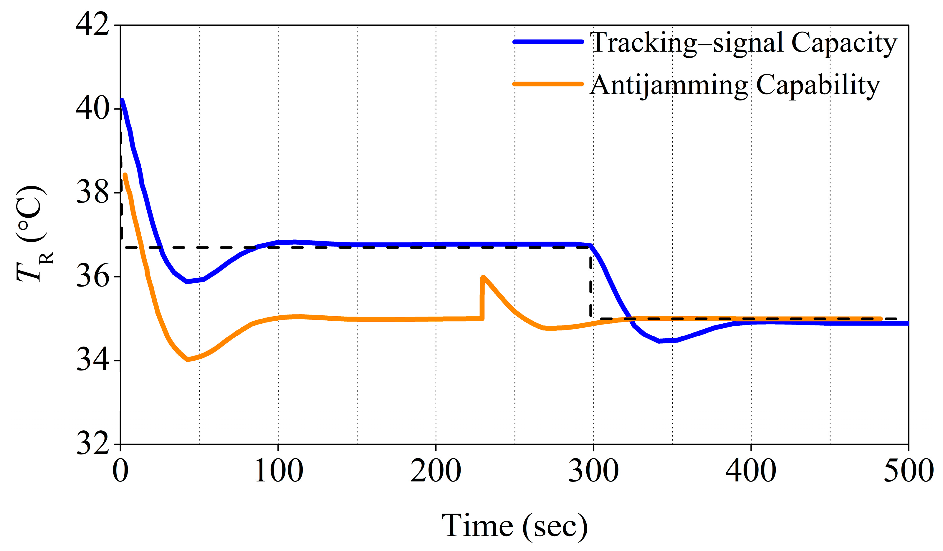
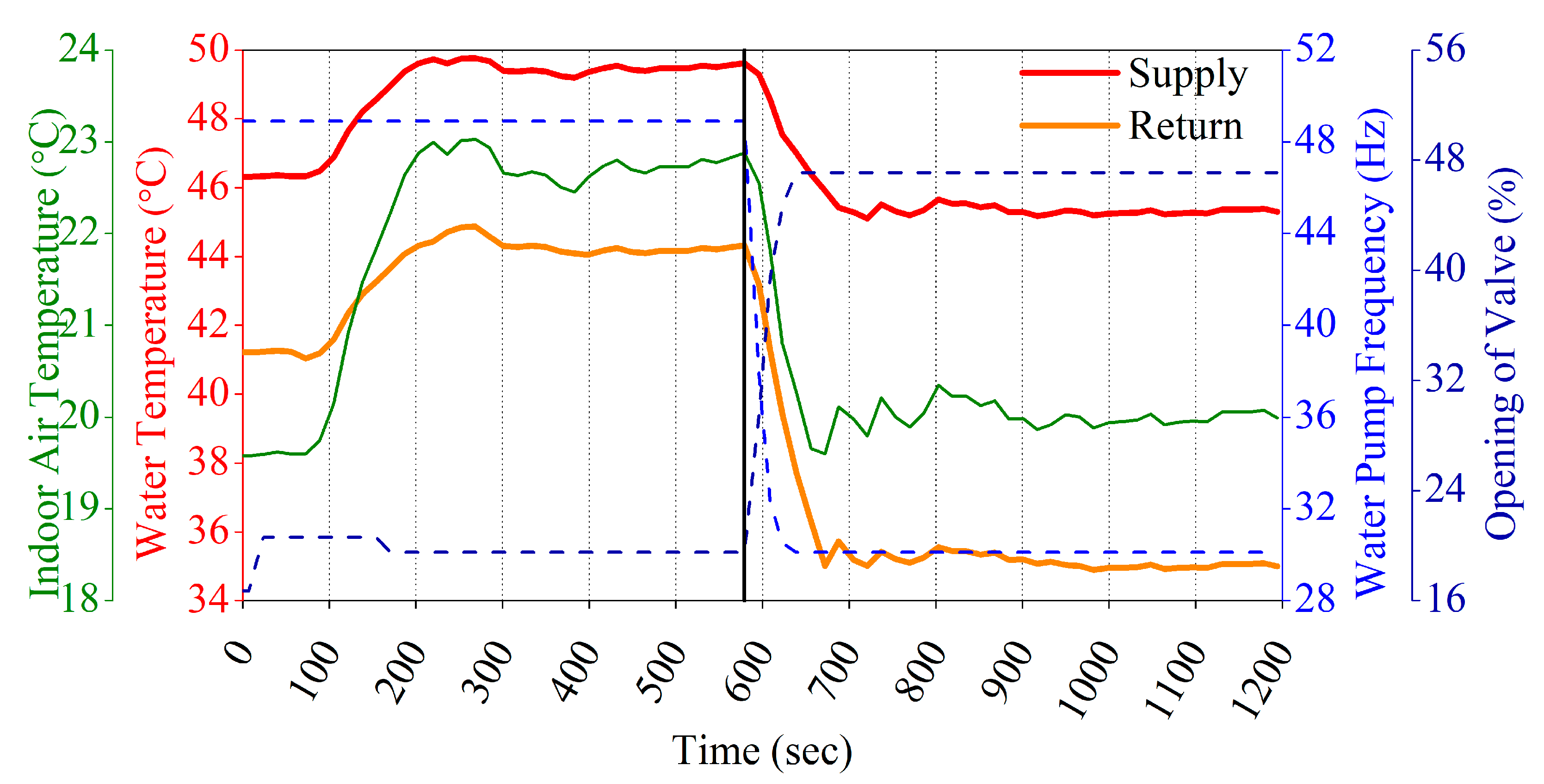
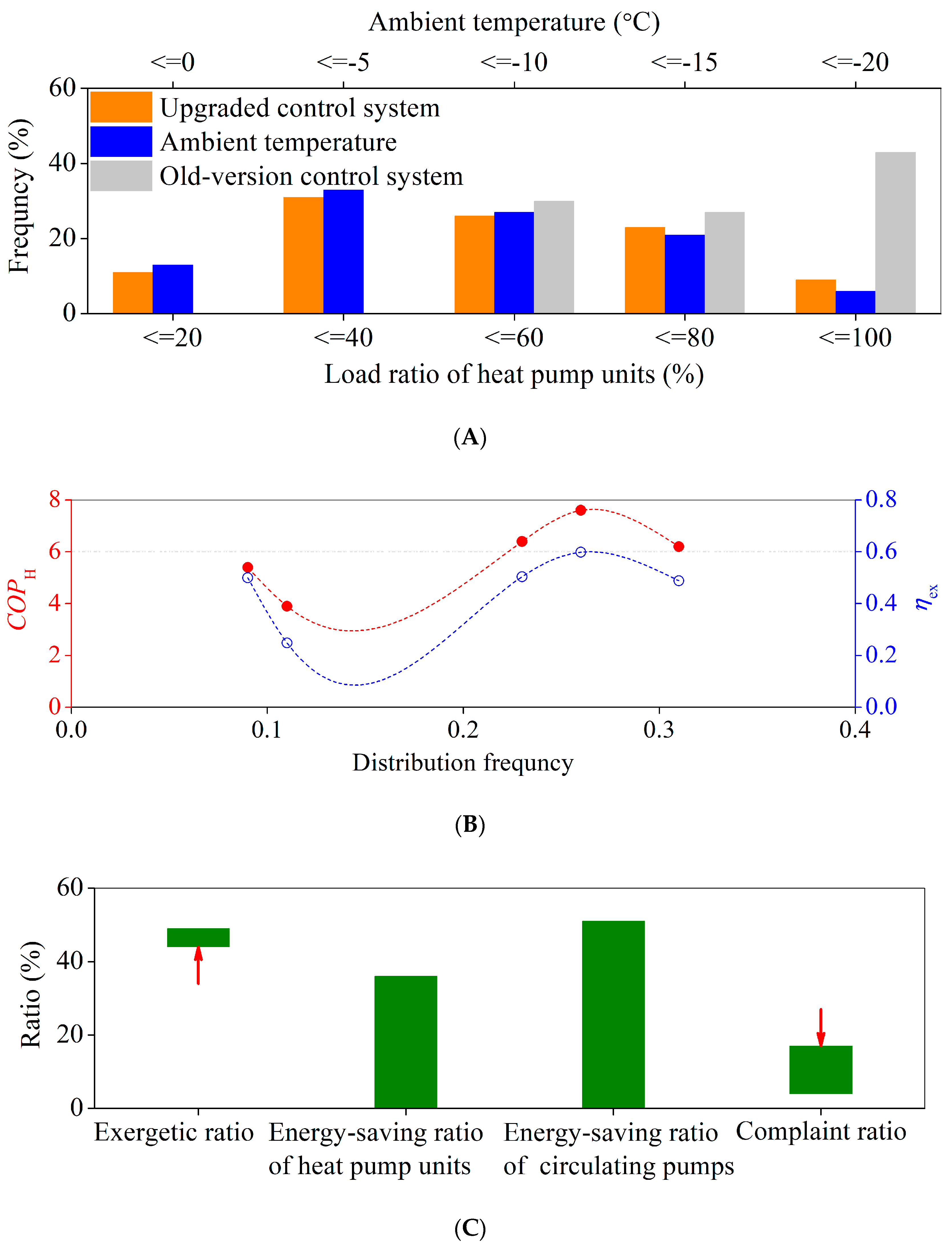
| KP1 | KI | KD1 | λ | μ1 | KP2 | KD2 | μ2 | ITUE |
| 30.71 | 9.76 | 50.56 | 0.77 | 0.61 | 1.11 | 60.88 | 0.79 | 1051 |
| tc | Ess | Overshoot | n:1 | |||||
| 99.31 sec | 5.87E-05 | 2.51% | 8:1 | |||||
Disclaimer/Publisher’s Note: The statements, opinions and data contained in all publications are solely those of the individual author(s) and contributor(s) and not of MDPI and/or the editor(s). MDPI and/or the editor(s) disclaim responsibility for any injury to people or property resulting from any ideas, methods, instructions or products referred to in the content. |
© 2024 by the authors. Licensee MDPI, Basel, Switzerland. This article is an open access article distributed under the terms and conditions of the Creative Commons Attribution (CC BY) license (http://creativecommons.org/licenses/by/4.0/).


