
Submitted:
11 October 2024
Posted:
14 October 2024
You are already at the latest version
Abstract
The safety and reliability of structures operating in cold regions are seriously threatened by icing. This has attracted researchers to explore de-icing/anti-icing methods. In this work, a bubble de-icing system was established and investigated for the removal of ice from frozen structures using bubble pulsation energy. Traditional de-icing method face high energy consumption, environmental pollution, and secondary icing issues. To avoid this and promote the development of de-icing techniques, the massive amount of energy generated by bubble pulsation can be used for de-icing. In the present work, experimental methods have been adopted to demonstrate the possibilities of de-icing using cavitation energy. Many test cases, in which the bubble distance from the target and thickness of ice layer were varied 5 - 35 mm, were examined to determine the mechanism of ice removal by the bubble energy. This research demonstrated that bubble energy can be used effectively for de-icing. Bubble energy
should be further explored for de-icing techniques and engineering application prospects.
Keywords:
bubble energy
; high speed jet
; de-icing
1. Introduction
The occurrence of icing is inevitable for structures operating in cold regions. Icing, which will reduce the stability and reliability of the structures, reduces the performances of engines, and affects radio and radar signal reception. In the field of aeronautical engineering [31], the accumulation of ice on aircraft structures (such as tails, wings, and engine components) may reduce the maximum lift capacity [30], increase the drag, and even threaten the safety of the aircraft in some cases [6]. In the field of ocean engineering, the icing of polar ship structures and polar offshore platforms will affect the seaworthiness of ships and the stability of offshore platforms. Particularly for polar ships with tall superstructures, the increase in the center of gravity and ship resistance caused by icing may lead to the overturning of ships and offshore platforms. The icing of the wires, cables, radar and other radio equipment of ships and offshore platforms will affect the reception of communication signals; and increase navigation difficulties when polar ships encounter issues (such as icy areas, and grounding). Icing will affect the normal operation of winches, valves, cranes and other equipment [22], thus threatening the safety of workers [33]. Therefore, anti-freezing and de-icing technology is essential and must be used continuously.
Generally, traditional de-icing technology is divided into active de-icing and passive de-icing based on the de-icing method. Active de-icing methods usually absorb large amounts of energy and resources from external sources, including mechanical energy, electric heating, and infrared rays. In contrast, passive de-icing methods use the paint itself to prevent ice from forming and combine with wind [10] or gravity to perform de-icing and consume energy. Currently, the most commonly used de-icing techniques are chemical de-icing, electric heating de-icing, and electric pulse de-icing. Xie et al. [32]systematically summarized de-icing methods, mainly including the following: manual de-icing, electric de-icing, high-speed heat flow de-icing, infrared de-icing, ultrasonic de-icing [8], chemical de-icing [25],sacrificial coating de-icing [13], and super hydrophobic coating de-icing methods [24,26,29]. The advantages and disadvantages and the scope of application of current de-icing techniques are summarized as follows. In the method of electric heating de-icing [23,42], electric heating devices [16],such as resistance wires, are used as the heat source to melt and remove the ice layer. The working principle is to convert the electrical energy of the generator into heat; its advantages are that the de-icing process is quick and convenient. The disadvantage is that in the process of energy conversion, there is more energy loss and secondary icing is more likely to occur. Electric de-icing is usually applied for de-icing on antennas, portholes and other facilities. High-speed heat flow de-icing method [27]uses high-temperature and high-pressure water vapor to melt the ice layer. Its advantage is that the generated heat energy can be recycled by engines, boilers and other equipment. The disadvantage is that there are restrictions on icing materials [20]; heat-sensitive materials [7,19]and brittle materials are not suitable. The method of infrared deicing irradiates the ice layer with different wavelengths of infrared rays [12,15]. The material absorbs the energy of the infrared rays to melt the ice layer. The key feature is to select the appropriate infrared wavelength without damaging the coating. Under the premise of melting the ice layer, the disadvantage is also the problem of secondary icing. The working principle of the ultrasonic guided deicing method is to use the vibrations of the ultrasonic guided waves to generate shear forces on the surface of the ice and the icing structure. When the force is greater than the adhesion strength of the ice, de-icing is achieved. Ultrasonic-guided-wave de-icing [5,35]avoids the disadvantages of a high energy consumption and secondary icing of thermal de-icing methods; however, its scope of application is limited to structures such as plates and pipes; chemistry. The method of material deicing is generally used on snow-covered roads [43]. Chemical products, such as calcium chloride and urea, are sprayed and applied to melt the ice. The disadvantages are corrosion of the equipment and environmental pollution. The disadvantage of the hydrophobic coating method is that the durability and stability of the coating are far inferior to those of water wettable coatings. Although many efforts have been made to improve de-icing methods, it is still challenging to explore low-energy-consumption, environmentally safe de-icing systems. Thus, it is necessary to develop a new de-icing method to use new energy to remove ice from frozen structures. Bubbles widely exist in nature. They are produced in various ways and are generally easy to obtain [38,41]. The power of large-scale bubbles generated rapidly is greater than may be expected. The energy of bubbles is mainly attributed to the high-speed jet generated during the break-up process; the jet has a strong destructive power. Zhang et al. [3,4]proposed the idea of bubble breaking ice for the first time in the world. Studies [3] have confirmed that bubbles can break ice [14,34]. Furthermore, a bubble generator can be used to prevent the water around a ship docking at the dock from freezing in winter. There are many methods for generating severely pulsating bubbles, such as electric spark experiments and laser bubbles. There are two main experimental methods for generating bubbles using electric sparks. One is high-voltage [2] ignition to generate bubbles, and the other is low-voltage ignition [28,39]. Both electrodes are connected to the two ends of the charging capacitor, and the system is short-circuited in water. EDM bubbles have the advantages of a low cost and simple operation [9]. Other method can be used to generate bubbles. The laser bubble method uses a laser to generate a cylindrical parallel laser beam with a certain radius [1,37]. The pulse energy is about 1 J. After the parallel laser beam passes through a magnifying glass with a certain focal length, the energy will be concentrated on the focal point of the magnifying glass. Located in still water, the water around the focal point quickly vaporizes under the high energy of the laser, generating high-temperature [17,21]and high-pressure bubbles to cause pulsation [1,5]. The method of generating bubbles [11,36] also includes reducing the pressure at a point in the flow field [18,40]. This paper proposes a de-icing system; based on generation and collapse of bubbles, and a process of using the bubble energy to remove the ice layer on the surface of the icing structure is studied. The destruction process under the pulsating energy of the bubble is examined. A bubble generator is adopted that uses electric sparks. This study focuses on the ability of bubbles to destruct the ice layer attached to frozen structures, and the efficiency of bubble deicing. The distance between different bubbles and the ice plate, as well as the ability of bubbles to remove the ice layer on the frozen structure under different ice thickness conditions were analyzed. This paper first introduces the basic principles of the bubble de-icing system. The efficiency of the de-icing system is then analyzed. Finally, the influence of different de-icing schemes on the de-icing efficiency is summarized.
2. Working Principle of Bubble Generating Device
2.1. Electric Spark Bubble Experiment Device
The purpose of this research is to use the energy generated by bubbles to remove ice from a frozen structure. The bubble generator system used in this work is based on the improved electric spark experiment by Khoo.The discharge power supply was a capacitor with a capacitance of 400 , and the voltage was 600 V. The positive and negative electrodes used copper wires that crossed each other with diameters of 0.2 mm. The internal principle circuit diagram of the bubble generator is shown in Figure 1. The transformer converted a 220 V alternating current (AC) power into a 2000 V direct current (DC) power supply; and charged the 400 capacitor bank to store andsupply energy to engender bubbles. The spark discharge can provide about 800 J available energy, which can be estimated as follows:
In which, U is the charging voltage, C is the capacitance of the capacitor. When the capacitor bank is discharged, a plasma zone formed around the electrode. Accompanied by plasma high temperature and high pressure discharge, the liquid around the electrode accelerated. High temperature and high pressure pulsating bubbles were generated through the gap between the two electrodes by the voltage discharge. The bubbles expand, and then shrink, and eventually collapse to form jets, which can break the ice, as was verified by Cui et al. [3]. The solution designed in this paper uses the energy of the bubble pulsation to remove the ice layer attached to an aluminum plate.
2.2. EDM Bubble Scale Law
Through the above-mentioned electric spark bubble generating device, the generated bubbles had good repeatability, that is, when the voltage is maintained, the discharge voltage and the overlapping method of the copper wire electrode remain unchanged, and the size of the bubble in free field is basically the same. The capacitance of the adjustable voltage transformer determined the intensity of the initial discharge energy. When the discharge voltage is kept constant, the initial internal pressure of the bubble also tended to be stable, and the maximum radius reached by the bubble pulsation energy was also determined. After conducting a large number of bubble experiments in the free field with the experimental device, it is found that the maximum radius of the bubbles was different under the different discharge voltage. When the discharge voltage is maintained at a certain level, the maximum radius of the initial bubble in the free field is basically the same. Multiple groups of free field bubble pulsation tests were carried out under different voltage conditions, and grouped the experimental measurement data to obtain the average maximum bubble radius and average period. According to the reference [20], the relationship between the energy of the pulsation bubble and the maximum radius of the bubble could be estimated as the following equation:
where, is the bubble energy , is the ambient pressure and denotes the maximum radius of the bubble.
3. Aluminum Plate Icing Technology
The material of the plate used here was 5052 aluminum alloy with tensile strength around 175 MPa, the density is 2.72 g/cm3, and the elastic modulus is 70 GPa. Aluminum is a low-temperature-resistant material, the strength of aluminum increases with the decrease in temperature, and the ductility of aluminum is better. It is not brittle, so it can be used as an ideal material for low-temperature equipment, and it is widely used in manufacturing industries, such as shipbuilding, aerospace, and machining. In this experiment, laser cutting technology was used to cut aluminum plates into 100 mm × 100 mm square plates with thicknesses ranging from 0.5 to 3 mm. During the experiment, the freezing technique shown in Figure 2 was used, where two freezing techniques (Figure 2 (a) and (b)) were used to obtain two ice samples. The first was a frost ice sample (Figure 2 (c)), the second type was a block ice sample (Figure 2(d)). The frost ice sample was generated using an atomization and icing process to simulate the icing process of the aluminum plate under air atomization conditions (Figure 2(a)). Boiling hot water was placed in a freezer, and evaporated vapor contacted an aluminum plate to atomize, forming droplets. Due to the temperature change and energy conversion, an icy layer gradually began to develop on the aluminum plate gradually began to develop on the aluminum plate, which could be obtained after about 36 h. The desired frosty ice sample (was thus obtained, as shown in Figure 2(c)), with an ice thickness of mm. The block ice sample was obtained via a special directional freezing technology to simulate the icing process (Figure 2(b)). A topless square container made of thermal insulation material was used. The aluminum plate was fixed on the top of the container horizontally and boiling hot water was injected from the bottom of the container. Because the bottom and the sides of the container were insulated, the freezing of water was gradual. The surface of the aluminum plate in contact with water and air reached the freezing point first, and the freezing process proceeded from top to bottom. The temperature of the air in the container was kept at, and finally after 48 h, a sample of frozen ice from the aluminum was obtained (Figure 2(d)). The ice was removed from the top and cut into ice samples with different thicknesses used in the experiments. The thickness of the ice used in this experiment varied from 5 to 30 mm. The Youngs modulus of the obtained ice was 9.31 GPa, and the Poissons ratio was 0.33.
4. Bubble De-Icing System Set-Up
The bubble de-icing system used in this article is presented in a schematic shown in Figure 3. The bubble de-icing system mainly included the following components: (1) spark bubble generating device; (2) transparent glass experimental water tank (500 mm×500 mm×500 mm); (3) LED lights (GS Vitec Multi LED LT-V8-11 7700 lumens), where light source interference was avoided to ensure images could be captured effectively; (4) high-speed camera (Vision Research Phantom V711), which had a capture rate of 24000–58000 frames per second, and an exposure time of 10∼20 ; (5) lens (Nikkor 50 mm F2.8); (6) computer. The bubble de-icing device is shown in Figure 3. The working process of the bubble de-icing device is as follows:
- (1)
- Deionized water was added to a plexiglass water tank (500 mm×500 mm×500 mm) to a height of 30 cm, and the water in the tank was kept degassed. The prepared aluminum-ice board could not be placed directly in the water tank without controlling the water temperature. Due to the temperature difference between the water and ice, the de-icing effect would be affected. The water tank temperature was controlled by adding ice cubes to cool the water. The temperature was 5;
- (2)
- The LED light was placed on the right side of the water tank, and the high-speed camera was placed on the front side of the water tank. The shooting angle of the camera was adjusted to ensure that the camera could capture the fractured area of the sheet of ice.
- (3)
- The clutch was installed on the wall of the water tank to rigidly fix the ice-covered aluminum plate, and the bubble generating device was placed in the lower part of the tank. Two copper pillar electrodes were installed under the free surface of the water tank to ensure the depth of the ice-aluminum plate structure at a fixed position on the surface of the free liquid surface.
- (4)
- The water was heated over a very short period of time when the positive and negative electrodes were inserted, generating bubbles that quickly began to expand. When the bubbles expanded to the maximum size, they began to contract, and then jets and shock waves were generated. The energy released removed the ice layer attached to the aluminum plate.
5. Experimental Study of Efficiency of Bubble De-Icing
Different bubble distance parameters were used: long, medium and short. The ice plates had different thicknesses: thick ice plate, medium thick ice plate, and thin ice plate. Multiple camera angles were used front view, oblique view, and bottom view to record the shapes of the bubbles in the process of bubble de-icing and the shapes of the cracks when the ice plate was separated from the aluminum plate at high speed. Furthermore, the relationship between the bubble de-icing efficiency and the specific non-dimensional parameters presented below.
5.1. Dimensionless Parameters
To standardize the experimental results, the maximum bubble radius is usually used as the characteristic length of the dimensionless parameter. It is determined by the average value measured in more than 100 experiments under the same discharge voltage. For example, for a discharge voltage of 600 V, the maximum bubble radius was about 18.0 mm and the standard deviation was 0.54 mm. In the experiment, the dimensionless distance parameter was defined as the distance parameter d from the center of the initial bubble to the lower surface of the ice-aluminum plate, and the thickness of the ice :
In order to estimate the efficiency of the bubble de-icing system approximately, the de-icing rate was defined as follows:
In which, d denotes the de-icing rate, is the removal ice area and is the total icing area.
5.2. Bubble Distance and De-Icing Efficiency
The bubble distance is an important parameter that affects the ice breaking ability. The influence of the choice of bubble distance on the efficiency of removing the ice layer attached to the aluminum plate structure is discussed in this section.
5.2.1. Large Distance De-Icing
Figure 4 shows the dynamics of a single air bubble placed initially at a large distance away from the aluminum plate, with the thin ice () and its effect on the ice-coated aluminum plate. Figure 4 shows that with the sparks from the positive and negative electrodes, an initially continuously expanding bubble (frames 1 and 2) was produced. The bubble expanded to a maximum size (frame 3) under the action of the internal high pressure. The bubble began to shrink (frames 47). During the collapse process, the top of the bubble was attracted to the ice, and the bottom of the bubble shrank faster and formed a jet shape. When the bubble shrank to a minimum, a jet towards the ice formed (frame 8). The jet caused the ice plate to crack, and the bubbles and jet did not contact the ice-aluminum plate before the ice broke. This was because when the jet hit the upper boundary of the bubble, the initial shock wave was released. This was consistent with the research conclusion of Zhang [3]. The shock wave was emitted from the bubble ring formed after the jet penetrated. The secondary reflected waves (compression waves and expansion waves) caused cracks in the ice plate, which separated the ice from the aluminum plate. In frames 9 and 10, the bubbles expanded again, and then collapsed (frames 11 and 12). According to the material characteristics of the ice, the circumferential stress value first reached the allowable stress of the ice. Therefore, the cracks appearing in the ice were circumferential cracks. Due to the large distance between the bubbles and the ice plate, the initial shock wave decayed rapidly. The crack area was small, and the crushing range was about 10%.
5.2.2. Middle Distance De-Icing
The dimensionless ice thickness parameter, the bubble deformation of de-icing at a medium distance, and the effect on the ice-coated aluminum plate can be observed in Figure 5. When the distance between the bubble and the ice was the medium value, a jet formed during the bursting of the bubble, and hit the ice-coated aluminum plate before the bubble reached the minimum volume. Before the jet was formed, there was only a small amount of air in a small gap. The jet penetrated the gap and hit the ice, cracks appeared on the ice plate (Frame 9), and the bubbles expanded, contracted and then collapsed. At this time, the de-icing area was about 80% of the total area.
5.2.3. Near Distance De-Icing
The bubble deicing effect of the ice plate with at close range is shown in Figure 6. The bubble was in contact with the ice-coated aluminum plate before it collapsed. During the expansion phase, bubble is adsorbed on the surface of the ice plate, making the shape of the bubble appear hemispherical (frame 4). The upper half formed a suction cup under the action of the ice-aluminum structure, while the lower end of the bubble continued to shrink until a sharp corner formed (frame 8), and the center of the sharp corner pointed upward toward the frozen structure to form a jet (frame 10). The jet moved rapidly at a certain speed and formed a ring at the bottom. The bubbles appeared in the form of circles (frame 15). During this process, the ice-aluminum structure did not appear to be cracked or detached. In the frame 16, the bubble rings caused the ice to break for the first time. The crushing started from the ice-aluminum interface and continued to expand. The final deicing efficiency can reached about 90
5.3. Influence of Ice Type for De-Icing Efficiency
Due to the complexity of the mechanical properties of ice, the interactions between the ice and bubbles were random, resulting in different sizes, numbers, and forms of ice cracks, and the specific cracks and failure modes were different. We selected ice-aluminum structures with different thicknesses to study the de-icing ability of bubbles.
5.3.1. Thick Lumpy Ice
A sample of the block ice-aluminum plate with an ice plate thickness ranging from 25 to 30 mm was selected, with . Due to the influence of the ice cutting, process and the room and water temperatures, the error of the ice plate thickness was about 1 mm. The de-icing process and de-icing range of a typical thick ice plate under the action of bubbles are shown in Figure 7. The cracks formed in the thick ice plate were dominated by radial cracks.
With the expansion and contraction of bubbles to the smallest volume, a jet formed (frame 4). The jet caused the initial crack of the ice plate (frame 5), and then the cracks began to expand (frame 5 and 6). The bubble expanded and contracted for the second time. The second impact occurred in the frame 11 and the crack expanded again. Frame 12 shows the final crack form, which covered about 40% of the area of the ice-coated aluminum plate.
5.3.2. Medium Lumpy Ice
A sample of the block ice-aluminum plate with the ice thickness ranging from 15 to 20 mm was selected, .
The shape of bubbles and the breaking of ice along the vertical thickness direction are visible in the front view. As shown in Figure 8, even if the bubbles did not touch the ice-aluminum plate structure, the ice surface broke when the bubbles are jetted. The first broken area was at the interface between ice and aluminum plate. This was caused by the reflection of the pressure wave generated by the impact. The shock wave was reflected at the ice-aluminum plate interface as an expansion wave, which caused tension. As a result, the ice began to break away from the aluminum plate.
The initiation, bifurcation and expansion of ice cracks under the action of shock waves generated by the bubbles can be observed from the bottom view. As shown in Figure 9, in the case of short-distance bubble de-icing, small cracks occurred on the ice surface during the initial expansion stage of the bubble (frame 2). Due to the short distance, the energy reaching the ice surface during the bubble expansion process could cause further expansion of ice cracks, and then with the contraction of bubbles and the generation of jets, the impact on the ice caused the second crack propagation. Under the conditions of a medium ice thickness, the ice cracks had irregular square shapes, rather than the radial cracks present in the thick case. A third crack tear occurred when the bubble shrank to the limit again. The bubble burst and released a series of shock waves. The rebound of the bubbles caused cracks in the ice, and the energy of the shock wave generated was converted into the fracture energy, which was the cause of the crack splitting. The de-icing time under this condition was 0.96 ms.
5.3.3. Thin Lumpy Ice
For the thickness of (5–10 mm) and the condition for ice removal was different, from the typical example in Figure 1. The crack initiated the bubble expansion (frame 2). The initiated crack was radial crack, and the contraction of the bubble caused the second split (frame 11). The bifurcation of the last crack occurred in frame 18. For the thinner ice attached to the aluminum plate, the expansion of the bubbles imposed a bending moment on the ice, and the propagation distance from the top to the bottom of the ice was relatively short, so the reflection vibration occurred earlier and caused fragmentation. The entire de-icing time was 1.45 ms.
5.3.4. Frost Ice
The process of bubble removal of frost ice is shown in Figure 11. It can be seen from Figure 11 that the bubble is sucked by the frost ice, and sharp corners appear in the initial expansion stage, and the sharp corners continue to elongate. Then the bubbles begin to shrink, forming a shape similar to an egg in the fifth frame. An interesting phenomenon is that the bubbles were still attracted by the frost ice in the contraction stage. The contraction state was not overall shrinkage, but a necking phenomenon in the middle (frame 7). The upper part of the bubble was attracted by the tension of . The contraction was slower, and the lower part of the bubble shrank rapidly, forming an umbrella bubble, as shown in frame 9, and then the bubble shrank to its limit state (frame 10). Different from the bubble shape of lumpy ice, the observed jet was emitted from the top instead of contracting from the bottom. The top and bottom of the bubbles were separated by the middle necked ring. After the jet occurred, the bottom and top of the bubble expanded and collapsed, respectively. Frosty ice was easier to remove, and a smaller bubble energy could achieve a 100% de-icing rate.
5.3.5. De-Icing Mode
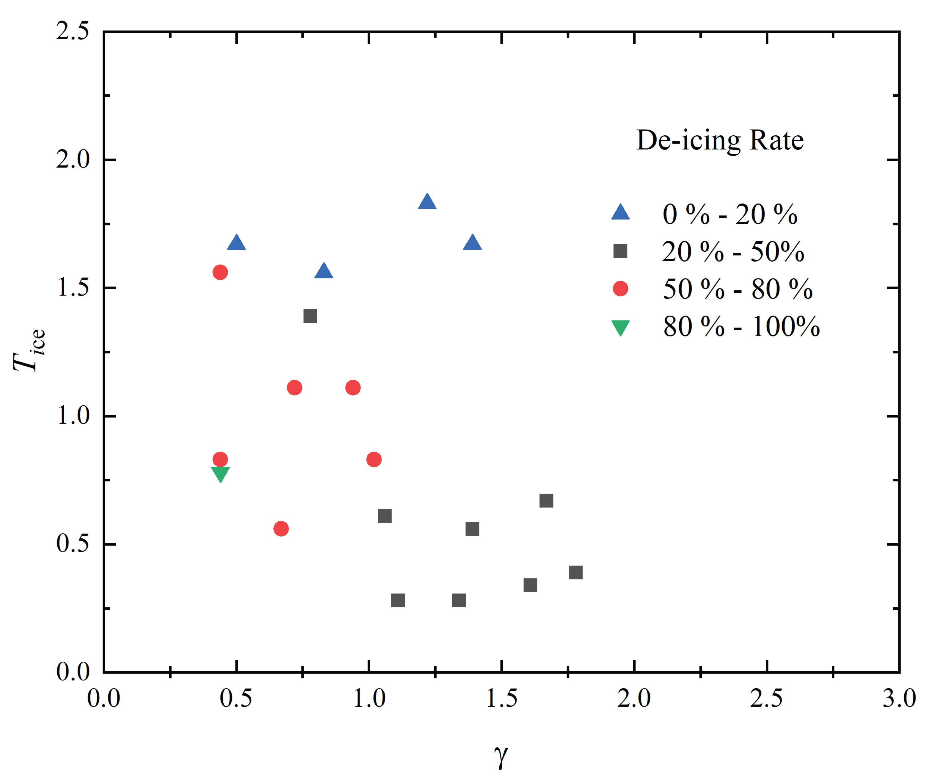
The relationship between the bubble deicing efficiency and is shown in Figure 12. Through the results of repeated experiments, the influencing factors of the de-icing efficiency are dimensionless ice thickness and the dimensionless distance . From Figure 12 we can find the most success de-icing rate occurred on the range of bubble dimensionless distance in and ice dimensionless thickness in . It is difficult to remove ice from aluminum plate one time when the thickness of ice larger than . For the ice plate in the range of less than 1.6 thickness. It is better to choose the bubble distance less than , the de-icing rate can achieve. For thicker ice, bubbles could not be removed from the aluminum plate after one trial, and multiple de-icing processes were required. Thin ice could be removed once with a certain bubble distance.
6. Conclusions
A novel bubble de-icing system was established in the present work, and its potential for removing ice from frozen structures using bubble pulsation energy was studied. The mechanism of the bubble de-icing and the mode of de-icing were examined, including processes with different bubble sizes and different thicknessed of the ice-coated on the aluminum plate. The summary of the bubble de-icing process and the mechanism of bubble de-icing were obtained. The main conclusions of this paper can be summarized as follows:
- (1)
- The energy released by bubbles can remove an ice layer attached to an aluminum plate structure. The pulsating pressure of the bubbles is the main load source for deicing. The jet of bubbles was the main cause of de-icing, and even when there was no contact with the ice-aluminum structure, the energy of the bubbles was sufficient to break the ice surface.
- (2)
- The efficiency of de-icing depended on the bubble distance. Bubbles have three different behaviors during the interaction with the ice-covered aluminum structure. For short-distance de-icing, the bubble behavior mainly manifested as a jet directed to the ice with subsequent annular bubbles. For long-distance de-icing, the bubbles collapsed at the far end after jetting. For frosty ice, the bubbles formed at the upper and lower ends, causing the phenomenon of necking and separation.
- (3)
- The crack formation pattern in the ice was related to the ice thickness. The thicker transparent block ice was dominated by radial cracks, and the thinner ice was prone to circumferential cracks. The movement of bubbles was regular, but the broken form of the ice was highly random, which was related to the complex physical properties of ice;
- (4)
- The de-icing efficiency was related to the non-dimensional ice thickness and the non-dimensional distance . The de-icing ratio was different under different parameter conditions. For thicker transparent block ice, multiple de-icing processes were required. For Frosty ice, was easier to remove, and the bubble energy was sufficient to achieve de-icing efficiency at one time. The de-icing system established in this paper provides a reference for using new energy sourses to solve engineering de-icing problems. As a novel de-icing method, bubble de-icing technology has good development prospects in renewable energy utilization. Bubbles are easy to obtain and have low energy costs. Furthermore, they are environmentally friendly and provide a high de-icing efficiency. Thus, bubble energy is expected to be widely used to solve many engineering problems, especially de-icing problems, in the future.
Author Contributions
Ying Song: Methodology, Data curation, Visualization, Writing. Shuai Zhang : Investigation, Review editing. Shi-ping Wang: Validation, Funding acquisition, Review editing. Zhuang Kang: Supervision, Resources, Review editing. All authors have read and agreed to the published version of the manuscript.
Acknowledgments
This work was supported by the National Natural Science Foundation of China(Grant No.51979049, Grant No.51909041).
Conflicts of Interest
The authors declare that they have no known competing financial interests or personal relationships that could have appeared to influence the work reported in this paper.
References
- Aleshkin, M.: A technique for suppressing bubble oscillations from an air gun during shallow-water marine seismic surveying. Moscow University Geology Bulletin 75(3), 305–308 (2020).
- Buogo, S., Plocek, J., Vokurka, K.: Efficiency of energy conversion in underwater spark discharges and associated bubble oscillations: Experimental results. Acta Acustica united with Acustica 95(1), 46–59 (2009). [CrossRef]
- Cui, P., Zhang, A.M., Wang, S., Khoo, B.C.: Ice breaking by a collapsing bubble. Journal of Fluid Mechanics 841, 287 (2018). [CrossRef]
- Cui, P., Zhang, A.M., Wang, S.P., Liu, Y.L.: Experimental study on interaction, shock wave emission and ice breaking of two collapsing bubbles. Journal of Fluid Mechanics 897 (2020). [CrossRef]
- Daniliuk, V., Xu, Y., Liu, R., He, T., Wang, X.: Ultrasonic de-icing of wind turbine blades: Performance comparison of perspective transducers. Renewable Energy 145, 2005–2018 (2020). [CrossRef]
- Ding, L., Chang, S., Yi, X., Song, M.: Coupled thermo-mechanical analysis of stresses generated in impact ice during in-flight de-icing. Applied Thermal Engineering 181, 115681 (2020). [CrossRef]
- Ding, L., Wang, X., Cui, X., Zhang, M., Chen, B.: Development and performance research of new sensitive materials for microwave deicing pavement at different frequencies. Cold Regions Science and Technology 181, 103176 (2021). [CrossRef]
- Gao, L., Liu, Y., Zhou, W., Hu, H.: An experimental study on the aerodynamic performance degradation of a wind turbine blade model induced by ice accretion process. Renewable Energy 133, 663–675 (2019).
- Gong, S., Goh, B., Ohl, S.W., Khoo, B.C.: Interaction of a spark-generated bubble with a rubber beam: Numerical and experimental study. Physical Review E 86(2), 026307 (2012).
- Habibi, H., Cheng, L., Zheng, H., Kappatos, V., Selcuk, C., Gan, T.H.: A dual de-icing system for wind turbine blades combining high-power ultrasonic guided waves and low-frequency forced vibrations. Renewable Energy 83, 859–870 (2015). [CrossRef]
- Han, R., Li, S., Zhang, A., Wang, Q.: Modelling for three dimensional coalescence of two bubbles. Physics of Fluids 28(6), 062104 (2016).
- Hao, L., Li, Q., Pan, W., Li, B.: Icing detection and evaluation of the electro-impulse de-icing system based on infrared images processing. Infrared Physics & Technology 109, 103424 (2020). [CrossRef]
- Huttunen-Saarivirta, E., Kuokkala, V.T., Kokkonen, J., Paajanen, H.: Corrosion behaviour of aircraft coating systems in acetate-and formate-based de-icing chemicals. Materials and corrosion 60(3), 173–191 (2009).
- Kan, X.Y., Zhang, A.M., Yan, J.L., Wu, W.B., Liu, Y.L.: Numerical investigation of ice breaking by a high-pressure bubble based on a coupled bem-pd model. Journal of Fluids and Structures 96, 103016 (2020).
- Koenig, G.G., Ryerson, C.C.: An investigation of infrared deicing through experimentation. Cold regions science and technology 65(1), 79–87 (2011).
- Li, B., He, L., Liu, Y., Luo, J., Zhang, G.: Influences of key factors in hot-air deicing for live substation equipment. Cold Regions Science and Technology 160, 89–96 (2019).
- Li, S., Zhang, A.M., Han, R., Cui, P.: Experimental and numerical study of two underwater explosion bubbles: Coalescence, fragmentation and shock wave emission. Ocean Engineering 190, 106414 (2019). [CrossRef]
- Li, S., Zhang, A.M., Han, R., Ma, Q.: 3d full coupling model for strong interaction between a pulsating bubble and a movable sphere. Journal of Computational Physics 392, 713–731 (2019). [CrossRef]
- Liu, X., Chen, H., Zhao, Z., Yan, Y., Zhang, D.: Slippery liquid-infused porous electric heating coating for anti-icing and de-icing applications. Surface and Coatings Technology 374, 889–896 (2019).
- Liu, Y., Kolbakir, C., Hu, H., Hu, H.: A comparison study on the thermal effects in dbd plasma actuation and electrical heating for aircraft icing mitigation. International Journal of Heat and Mass Transfer 124, 319–330 (2018).
- Liu, Y.L., Zhang, A.M., Tian, Z.L., Wang, S.P.: Dynamical behavior of an oscillating bubble initially between two liquids. Physics of Fluids 31(9), 092111 (2019). [CrossRef]
- Ma, L., Zhang, Z., Gao, L., Liu, Y., Hu, H.: An exploratory study on using slippery-liquid-infused-porous-surface (slips) for wind turbine icing mitigation. Renewable Energy 162, 2344–2360 (2020).
- Mohammed, A.G., Ozgur, G., Sevkat, E.: Electrical resistance heating for deicing and snow melting applications: Experimental study. Cold Regions Science and Technology 160, 128–138 (2019). [CrossRef]
- Nguyen, T.B., Park, S., Lim, H.: Effects of morphology parameters on anti-icing performance in superhydrophobic surfaces. Applied Surface Science 435, 585–591 (2018). [CrossRef]
- Rashid, T., Khawaja, H.A., Edvardsen, K.: Review of marine icing and anti-/de-icing systems. Journal of Marine Engineering & Technology 15(2), 79–87 (2016).
- Shen, Y., Wang, G., Tao, J., Zhu, C., Liu, S., Jin, M., Xie, Y., Chen, Z.: Anti-icing performance of superhydrophobic texture surfaces depending on reference environments. Advanced Materials Interfaces 4(22), 1700836 (2017). [CrossRef]
- Shu, L., Qiu, G., Hu, Q., Jiang, X., McClure, G., Liu, Y.: Numerical and experimental investigation of threshold de-icing heat flux of wind turbine. Journal of Wind Engineering and Industrial Aerodynamics 174, 296–302 (2018). [CrossRef]
- Sun, Y., Timoshkin, I.V., Given, M., Wilson, M., Wang, T., MacGregor, S., Bonifaci, N.: Acoustic impulses generated by air-bubble stimulated underwater spark discharges. IEEE Transactions on Dielectrics and Electrical Insulation 25(5), 1915–1923 (2018). [CrossRef]
- Thomas, S.K., Cassoni, R.P., MacArthur, C.D.: Aircraft anti-icing and de-icing techniques and modeling. Journal of aircraft 33(5), 841–854 (1996).
- Wang, Q., Yi, X., Liu, Y., Ren, J., Li, W., Wang, Q., Lai, Q.: Simulation and analysis of wind turbine ice accretion under yaw condition via an improved multi-shot icing computational model. Renewable Energy 162, 1854–1873 (2020).
- Wang, Y., Xu, Y., Huang, Q.: Progress on ultrasonic guided waves de-icing techniques in improving aviation energy efficiency. Renewable and Sustainable Energy Reviews 79, 638–645 (2017). [CrossRef]
- Wang, Y., Xu, Y., Lei, Y.: An effect assessment and prediction method of ultrasonic de-icing for composite wind turbine blades. Renewable Energy 118, 1015–1023 (2018).
- Wang, Y., Xu, Y., Su, F.: Damage accumulation model of ice detach behavior in ultrasonic de-icing technology. Renewable Energy 153, 1396–1405 (2020). [CrossRef]
- Yuan, G.Y., Ni, B.Y., Wu, Q.G., Xue, Y.Z., Zhang, A.M.: An experimental study on the dynamics and damage capabilities of a bubble collapsing in the neighborhood of a floating ice cake. Journal of Fluids and Structures 92, 102833 (2020).
- Zeng, J., Song, B.: Research on experiment and numerical simulation of ultrasonic de-icing for wind turbine blades. Renewable Energy 113, 706–712 (2017). [CrossRef]
- Zhang, A., Cui, P., Cui, J., Wang, Q.: Experimental study on bubble dynamics subject to buoyancy. Journal of Fluid Mechanics 776(137-160), 15 (2015). [CrossRef]
- Zhang, A., Li, S., Cui, J.: Study on splitting of a toroidal bubble near a rigid boundary. Physics of Fluids 27(6), 062102 (2015). [CrossRef]
- Zhang, A., Liu, Y.: Improved three-dimensional bubble dynamics model based on boundary element method. Journal of Computational Physics 294, 208–223 (2015). [CrossRef]
- Zhang, A., Ni, B.: Influences of different forces on the bubble entrainment into a stationary gaussian vortex. Science China Physics, Mechanics and Astronomy 56(11), 2162–2169 (2013). [CrossRef]
- Zhang, A., Wu, W., Liu, Y., Wang, Q.: Nonlinear interaction between underwater explosion bubble and structure based on fully coupled model. Physics of Fluids 29(8), 082111 (2017). [CrossRef]
- Zhang, A.m., Yang, W.S., Huang, C., Ming, F.r.: Numerical simulation of column charge underwater explosion based on sph and bem combination. Computers & Fluids 71, 169–178 (2013). [CrossRef]
- Zhao, Z., Chen, H., Liu, X., Liu, H., Zhang, D.: Development of high-efficient synthetic electric heating coating for anti-icing/de-icing. Surface and Coatings Technology 349, 340–346 (2018). [CrossRef]
- Zilioniene, D., Laurinavicius, A.: De-icing experience in lithuania. The Baltic Journal of Road and Bridge Engineering 2(2), 73–79 (2007).
Figure 1.
Schematic of the bubble de-icing system.
Figure 2.
Schematic of freezing techniques and obtained ice.
Figure 3.
Schematic of the bubble de-icing system.
Figure 4.
Time series of bubble dynamics showing the bubble jet impact on the ice-aluminum plate. (Bubble, and jet not in contact with the ice; shock wave removed ice from the aluminum plate.
Figure 4.
Time series of bubble dynamics showing the bubble jet impact on the ice-aluminum plate. (Bubble, and jet not in contact with the ice; shock wave removed ice from the aluminum plate.
Figure 5.
Medium distance bubble de-icing (Jet formed from the bottom, turned into ring, and impacted the ice).
Figure 5.
Medium distance bubble de-icing (Jet formed from the bottom, turned into ring, and impacted the ice).
Figure 6.
Near distance de-icing (Jet formed from the bottom of the bubble; ice breaking initialized from the interface of the ice and aluminum).
Figure 6.
Near distance de-icing (Jet formed from the bottom of the bubble; ice breaking initialized from the interface of the ice and aluminum).
Figure 7.
Thick ice crack patterns by bubble impact.
Figure 8.
Removal process of medium thick ice
Figure 9.
Medium thickness ice crack pattern by bubble impact.
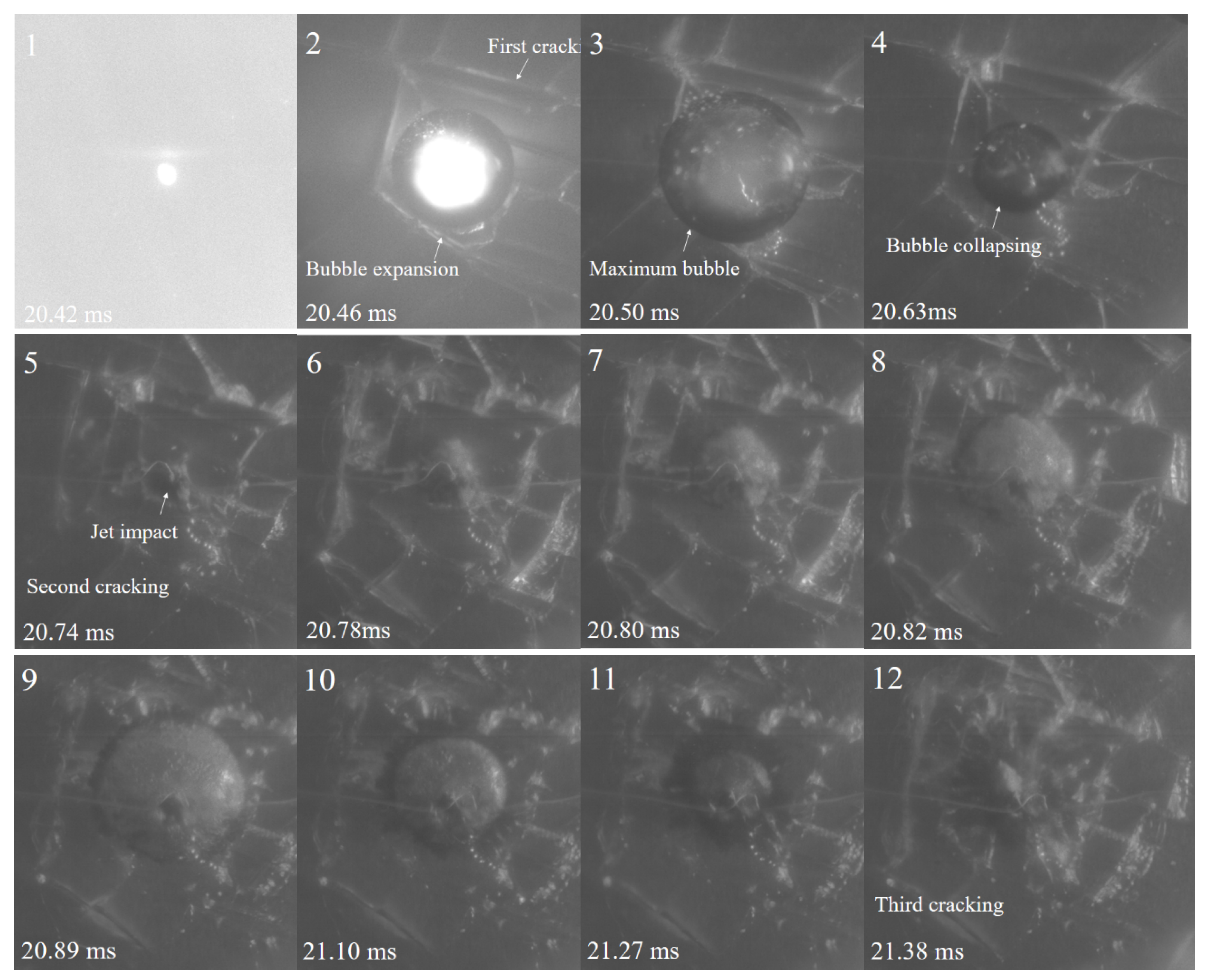
Figure 10.
Medium thickness ice crack pattern by bubble impact.
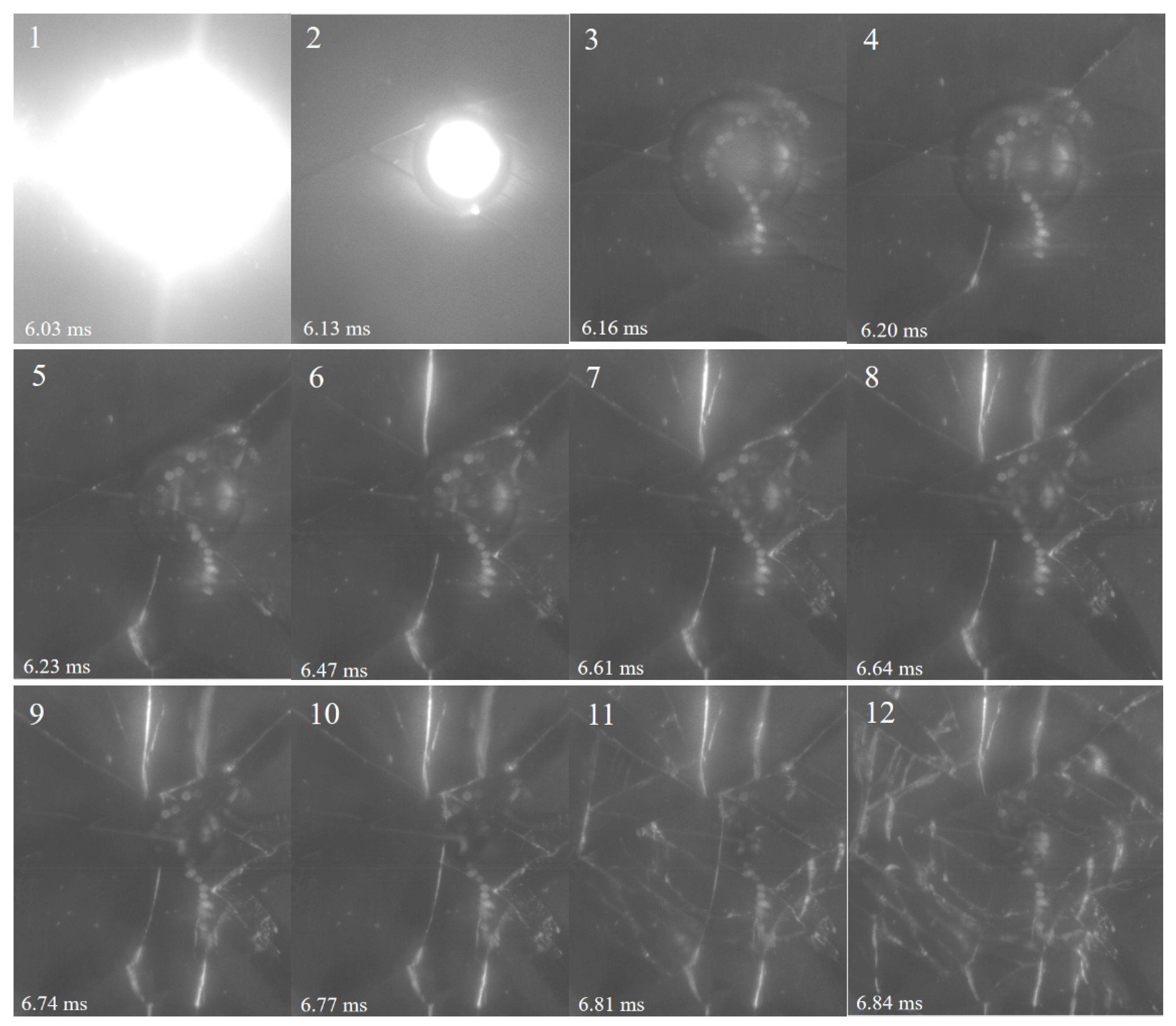
Figure 11.
Near distance de-icing (Jet formed from the bottom of the bubble; ice breaking initialized from the interface of the ice and aluminum).
Figure 11.
Near distance de-icing (Jet formed from the bottom of the bubble; ice breaking initialized from the interface of the ice and aluminum).
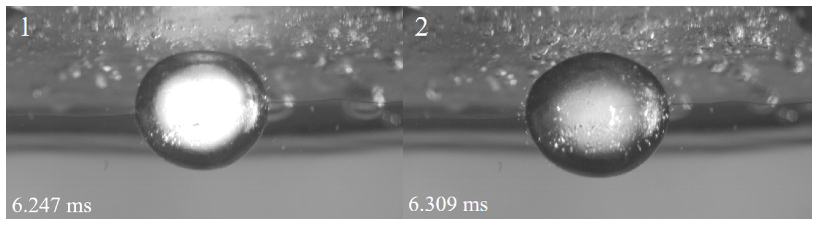
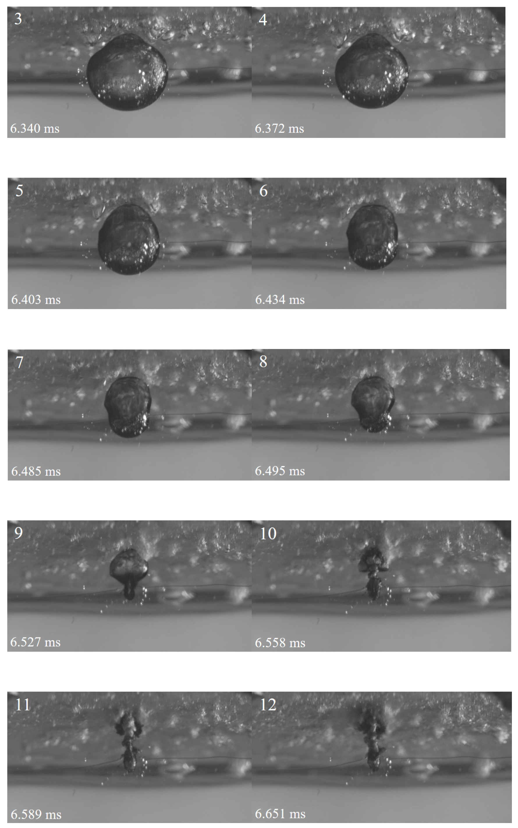
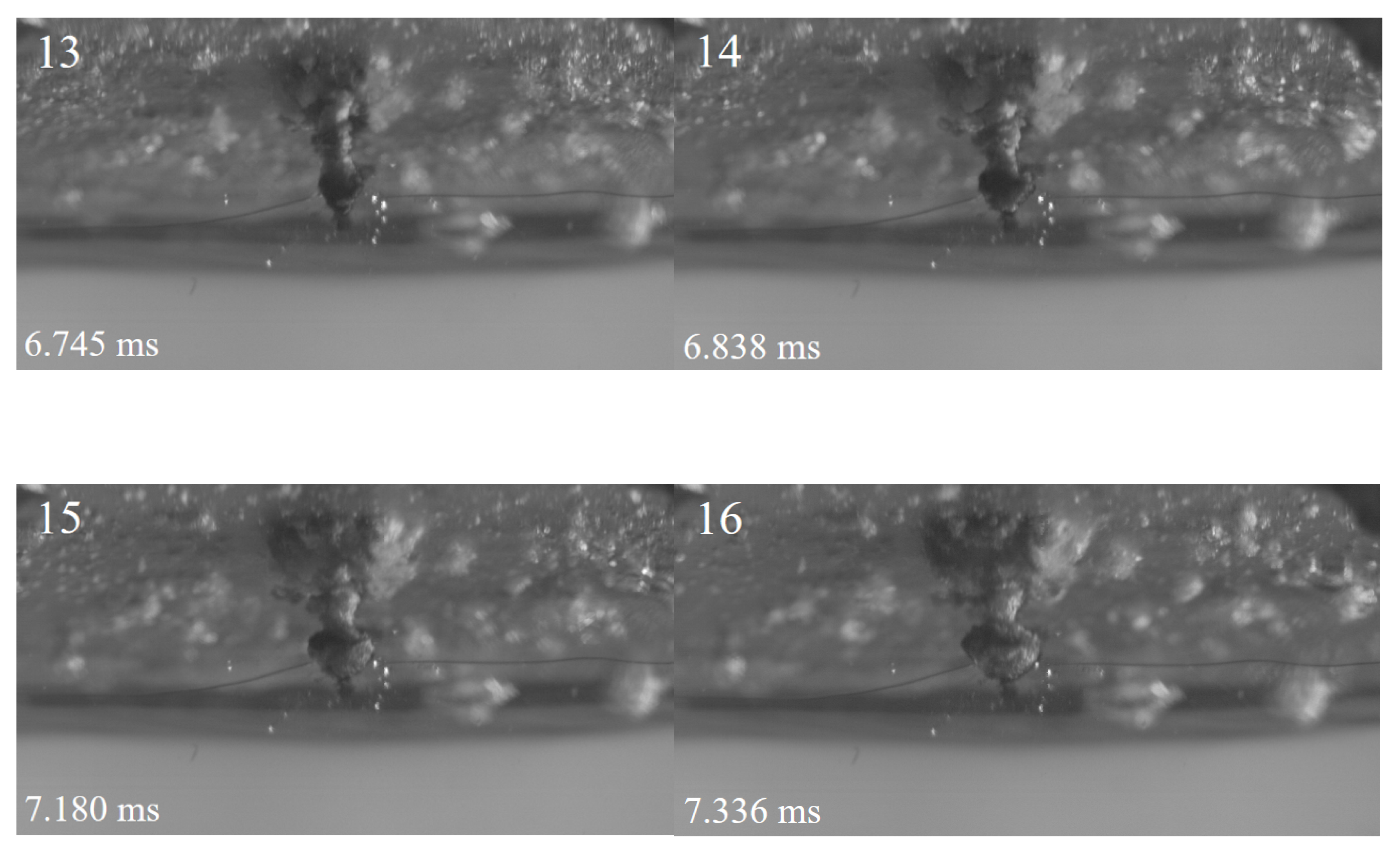
Figure 12.
Relationship between the de-icing possibility with ice thickness and distance .
Disclaimer/Publisher’s Note: The statements, opinions and data contained in all publications are solely those of the individual author(s) and contributor(s) and not of MDPI and/or the editor(s). MDPI and/or the editor(s) disclaim responsibility for any injury to people or property resulting from any ideas, methods, instructions or products referred to in the content. |
© 2024 by the authors. Licensee MDPI, Basel, Switzerland. This article is an open access article distributed under the terms and conditions of the Creative Commons Attribution (CC BY) license (http://creativecommons.org/licenses/by/4.0/).
Copyright: This open access article is published under a Creative Commons CC BY 4.0 license, which permit the free download, distribution, and reuse, provided that the author and preprint are cited in any reuse.


