Submitted:
04 November 2024
Posted:
05 November 2024
You are already at the latest version
Abstract
Keywords:
1. Introduction
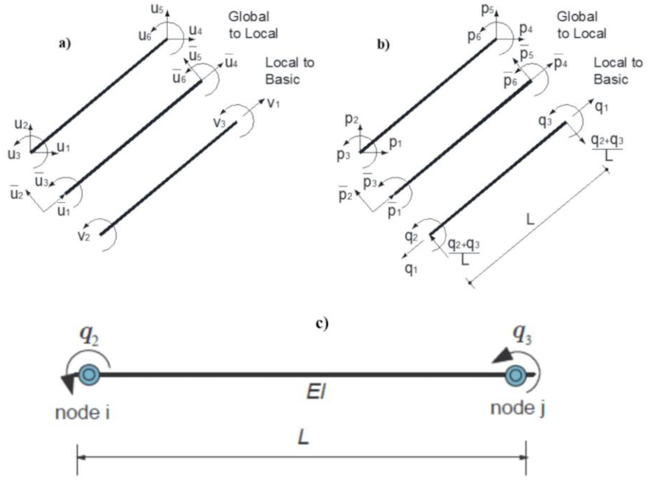
- The formulation of path-dependent one-component element response with strength degradation due to shear and axial failures is described in detail.
- A self-developed MATLAB [32] code is created in order to run a nonlinear dynamic analysis on one-story, two-bay reinforced concrete frame experiencing both shear and axial failures and was simulated with the above formulated beam element.
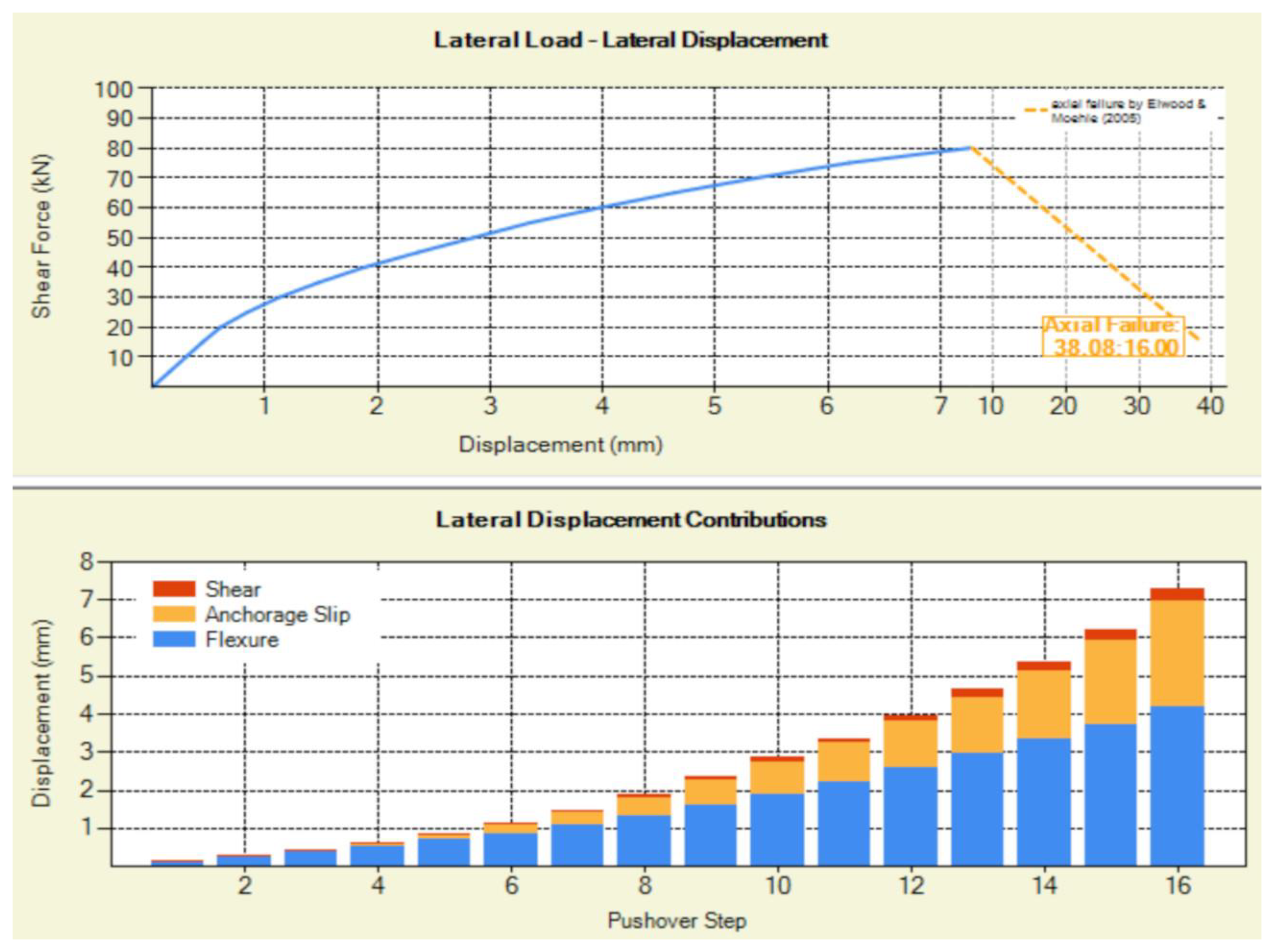
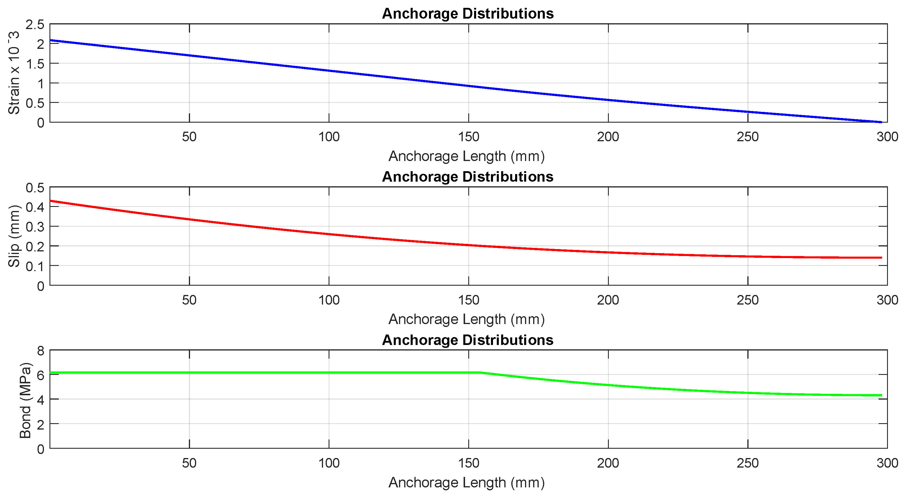
- The proposed analytical model can also address the stress state of a column under full cyclic load reversals, accounting for both flexure- and shear-dominated response conditions in RC columns, while also considering the contribution of anchorage or lap-splice pullout slip to the total drift.
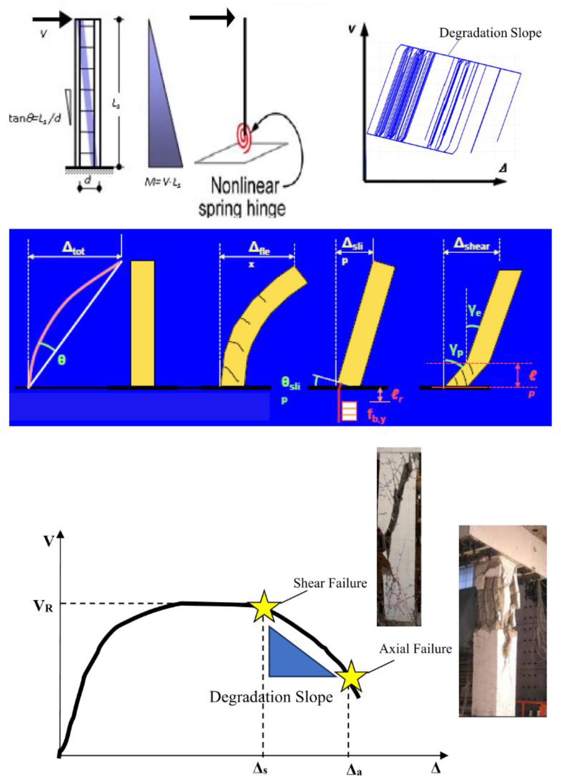
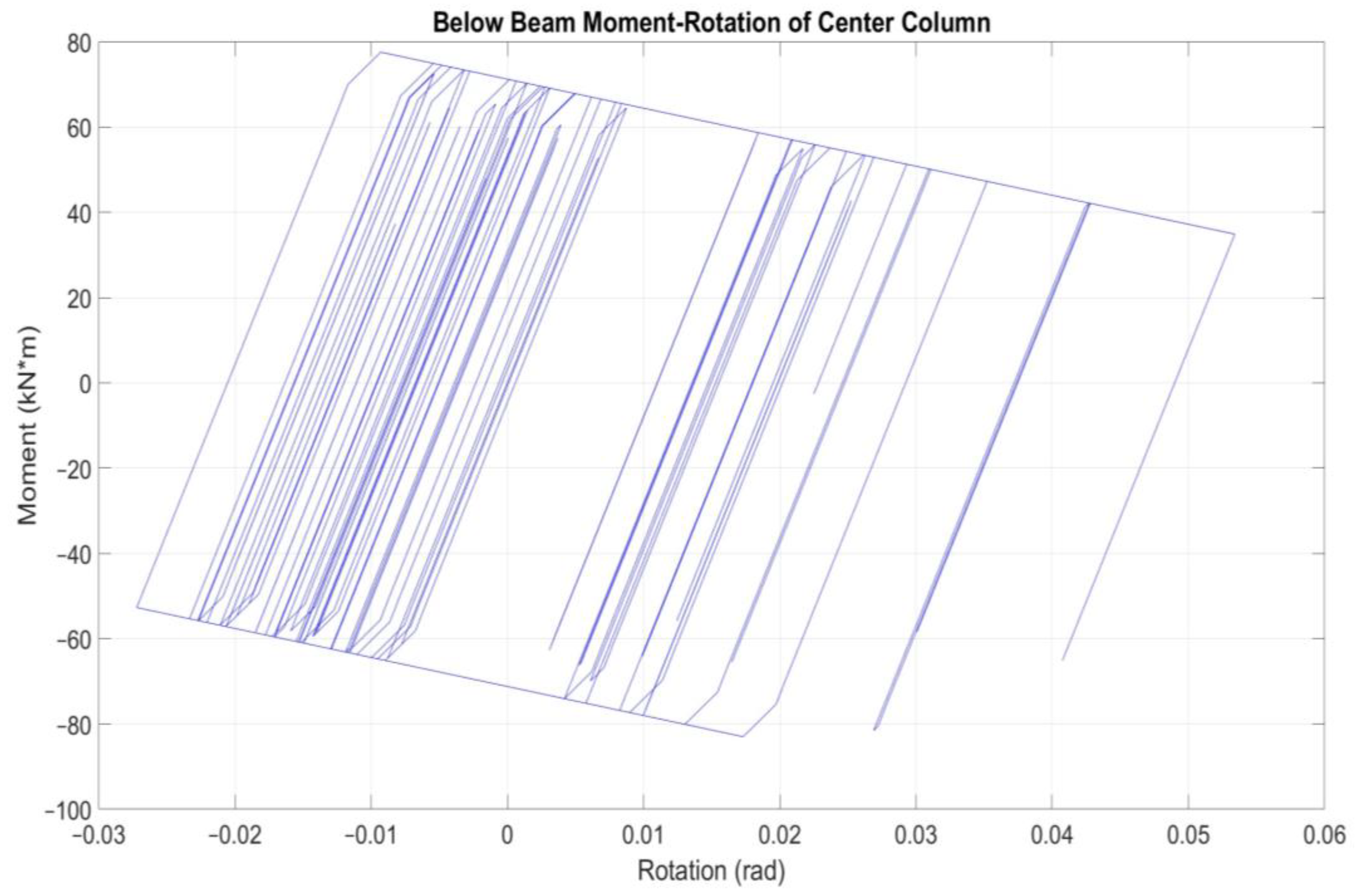
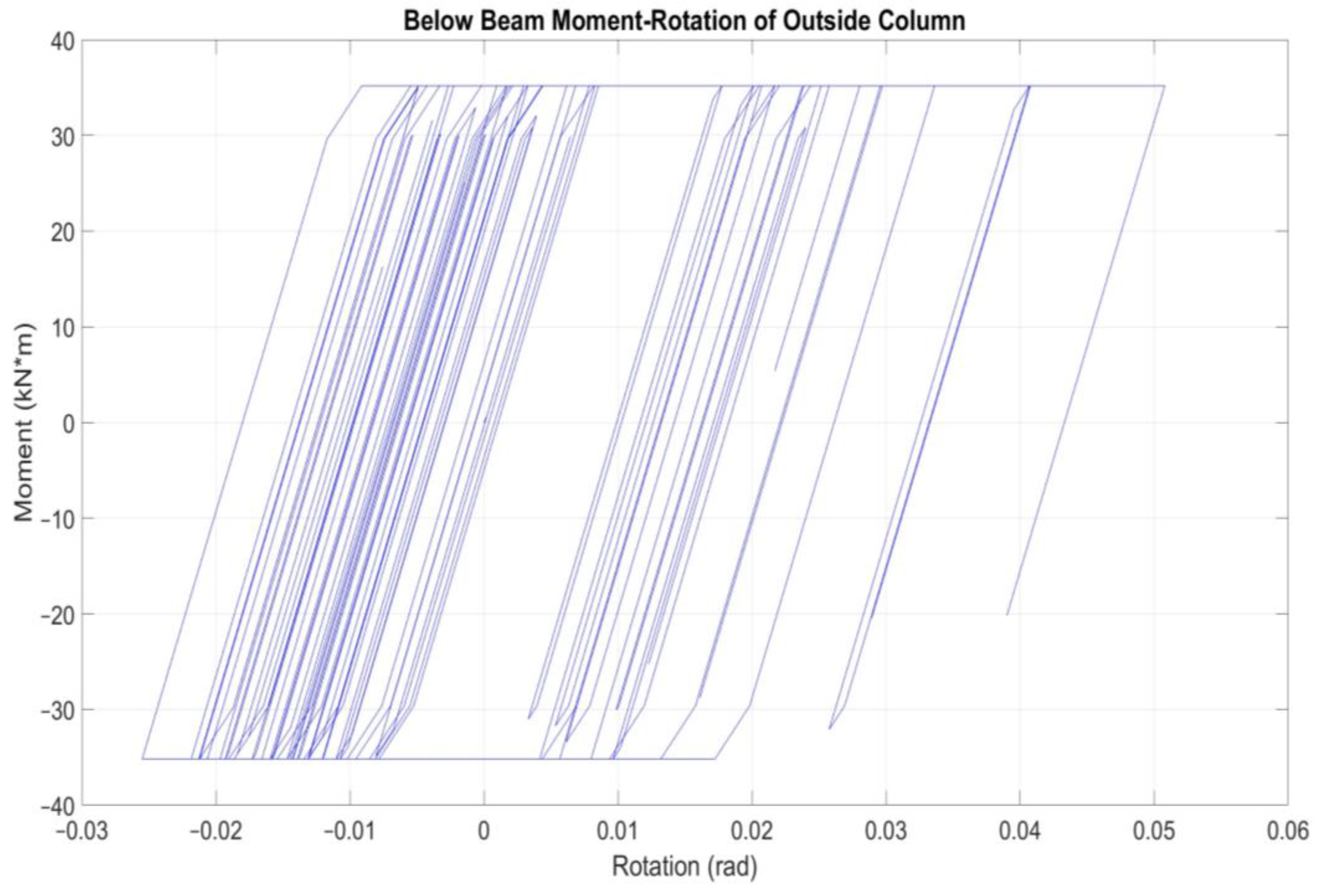
- A reduced computational model for prediction of dynamic response of old reinforced concrete structures under seismic loads is developed based on the moment-rotation envelope results from cantilever shear-critical columns analyzed by Phaethon Windows software.
- Inelastic frame structure experiencing shear, axial or pull-out failures are modeled in this study by placing a rigid plastic spring at the location where shear failure is predicted considering the contribution of anchorage and pullout slip in the total drift and applying a degradation slope. The negative slope connects the point on the moment-rotation envelope where shear failure occurs to the point of axial failure.
- The proposed approach advantage is the inelastic deformation at the member ends depends solely on the moment applied at the end, allowing any moment-rotation hysteretic model to be assigned to the spring hence simplifying the analytical and numerical modeling.
2. Materials and Methods
2.1. Path-Dependent Element Response with Strength Degradation
- Additive deformation decomposition
- Force-deformation relation
- Yield condition with
- Flow rule iff
- Kuhn – Tucker conditions and and for k=2,3
- Consistency condition for k=2,3
2.2. Experimental Test Setup
3. Results
3.1. Pushover Analysis of Center Shear-Critical RC Cantilever Column.
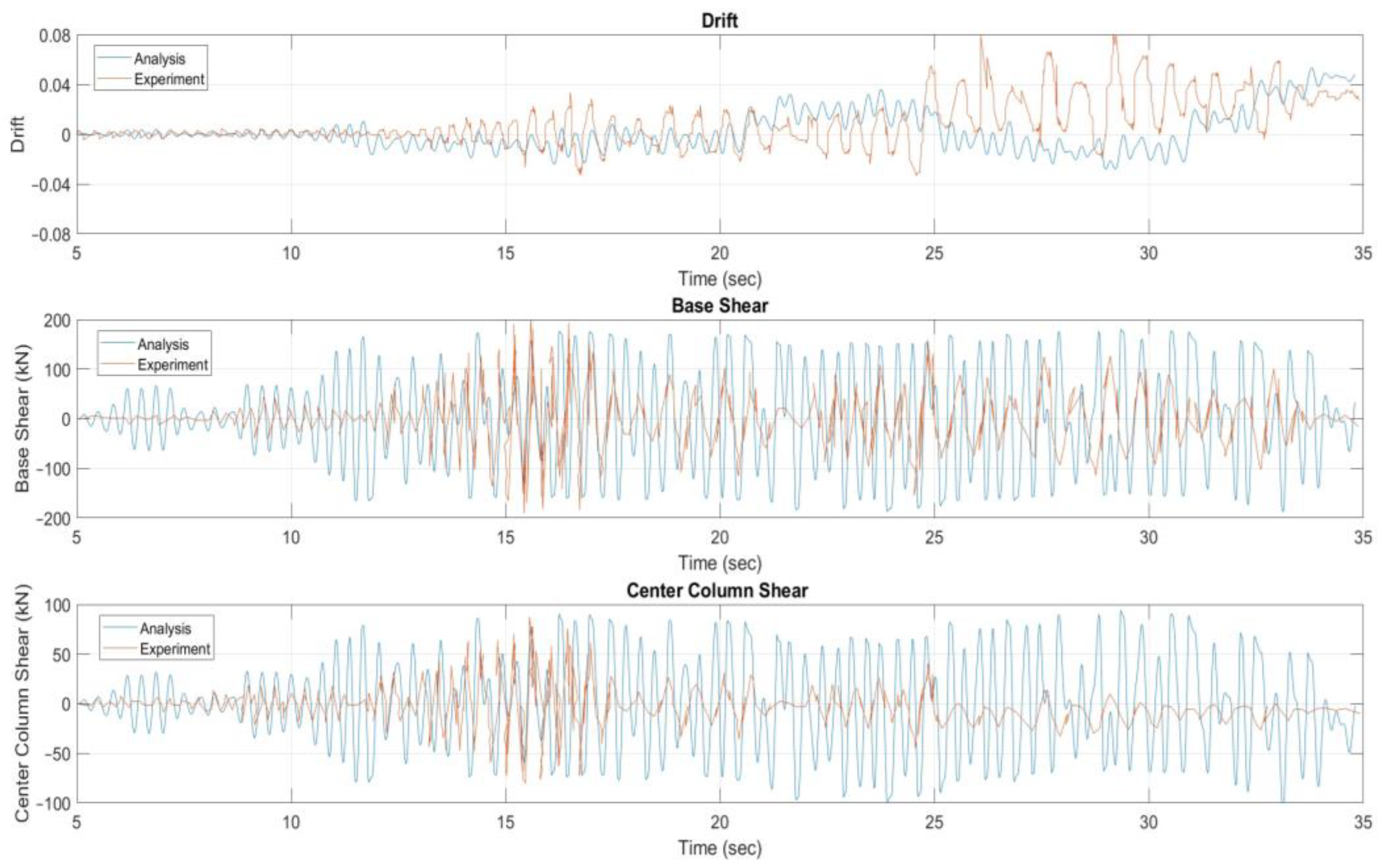
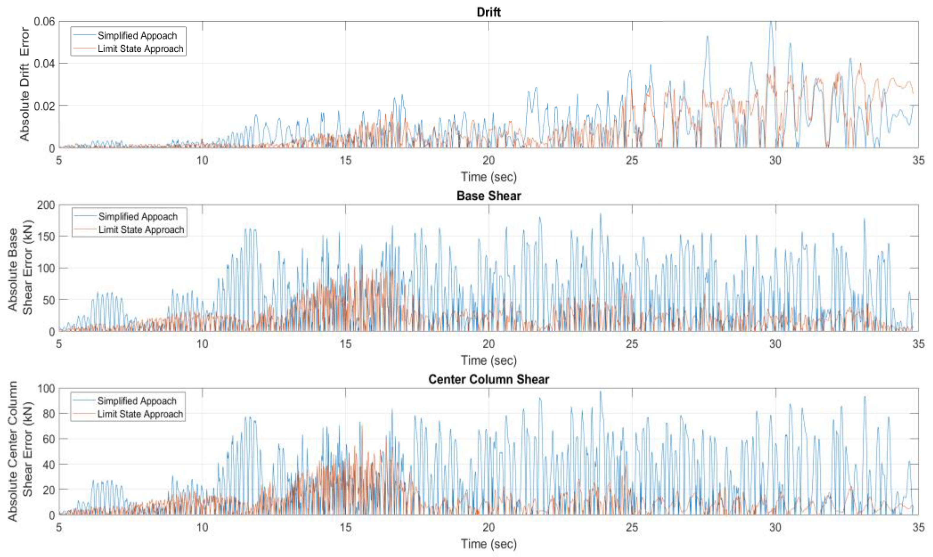
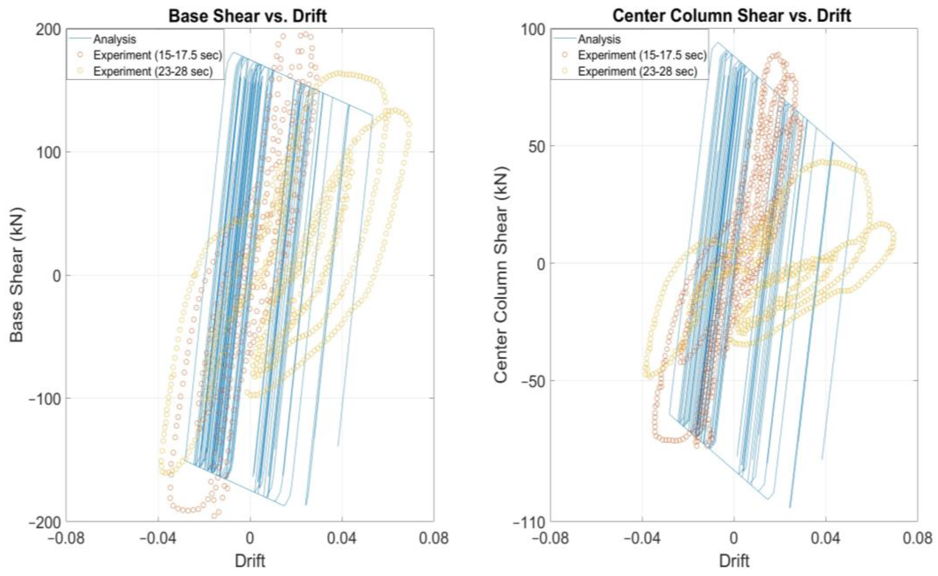
3.2. Nonlinear Time-History Analysis of Specimen 2
4. Discussion
5. Conclusions
Data Availability Statement
Conflicts of Interest
References
- Megalooikonomou K.G. Modeling the behavior of shear-critical reinforced concrete columns under lateral loads. Ph.D. Thesis, Department of Civil and Environmental Engineering, Faculty of Engineering, University of Cyprus, Nicosia, Cyprus, December 2019. [CrossRef]
- Megalooikonomou, K.G. Seismic Assessment and Retrofit of Reinforced Concrete Columns, 1st ed.; Cambridge Scholars Publishing: Newcastle upon Tyne, UK, ISBN (10): 1-5275-2785-9, ISBN (13): 978-1-5275-2785-0, 2019; p. 387. [Google Scholar]
- Elwood, K.J.; Moehle, J.P. Drift capacity of reinforced concrete columns with light transverse reinforcement. Earthquake Spectra 2005, 21, 71–89. [Google Scholar] [CrossRef]
- Elwood, K.J.; Moehle, J.P. Axial Capacity Model for Shear-Damaged Columns. ACI Structural Journal 2005, 102, 578–587. [Google Scholar]
- Asteris, P.G.; Antoniou, S.T.; Sophianopoulos, D.S.; Chrysostomou, C.Z. Mathematical Macromodeling of Infilled Frames: State of the Art". Journal of Structural Engineering ASCE 2011, 137, 1508–1517. [Google Scholar] [CrossRef]
- Gicev V., Trifunac M.D., Non-linear earthquake waves in seven-storey reinforced concrete hotel, Report CE 06-03, 2006, Dept. of Civil Eng. Univ. of Southern California, Los Angeles, California.
- Palomo, I.R.I.; Frappa, G.; de Almeida, L.C.; Trautwein, L.M.; Pauletta, M. Analytical and numerical models to determine the strength of RC exterior beam–column joints retrofitted with UHPFRC. Engineering Structures 2024, 312, 118244. [Google Scholar] [CrossRef]
- ACI Committee 318 Building Code Requirements for Structural Concrete (ACI 318-14) and Commentary, American Concrete Institute, Farmington Hills, MI. USA, 2014.
- Fib Model Code Chapter 6: Interface Characteristics, Ernst & Sohn Publications, Berlin, Germany, 2010.434.
- AASHTO LRFD Bridge Design Specifications and Commentary, 3rd Edition, American Association of State Highway Transportation Officials, Washington, D.C, 2013 1264.
- Morsch, E. Der Eisenbetonbau-Seine Theorie und Anwendung, 5th Edition, Vol. 1, Part 1, 1922, Wittwer, Stuttgart, Germany.
- Ritter, W. Die Bauweise Hennebique. Schweizerische Bauzeitung 1899, 33, 59–61. [Google Scholar]
- EN 1992-1-1: Eurocode 2: Design of concrete structures – Part 1-1: General rules and rules for buildings, European Committee for Standardization (CEN), Brussels, 2004.
- Vecchio, F.J.; Collins, M.P. The modified compression field theory for reinforced concrete elements subjected to shear. ACI Journal Proceedings, 1986, 83, 219–231. [Google Scholar]
- Filippou, F. C. , and Fenves, G. L. Methods of analysis for earthquake-resistant structures. In: Bozorgnia Y, Bertero VV (eds) Earthquake engineering: From engineering seismology to performance-based engineering. CRC Press, Boca Raton, 2004.
- Mergos, P.E.; Kappos, A.J. A distributed shear and flexural flexibility model with shear–flexure interaction for R/C members subjected to seismic loading. Earthquake Engng. Struct. Dyn. 2008, 37, 1349–1370. [Google Scholar] [CrossRef]
- Ceresa, P.; Petrini, L.; Pinho, R. Flexure-shear fiber beam-column elements for modeling frame structures under seismic loading-state of the art. J. Earthq. Eng. 2007, 11, 46–88. [Google Scholar] [CrossRef]
- Vecchio, F.J.; Collins, M.P. Predicting the Response of Reinforced Concrete Beams Subjected to Shear Using Modified Compression Field Theory. ACI Struct. J. 1988, 85, 258–268. [Google Scholar]
- Zeris, C.A. Three-Dimensional Nonlinear Response of Reinforced Concrete Buildings. Ph.D. Thesis, Department of Civil and Environmental Engineering, University of California, Berkeley, California, USA, 1986. [Google Scholar]
- Bentz, E.C. Sectional Analysis of Reinforced Concrete Members. PhD Thesis, Department of Civil Engineering, University of Toronto, Toronto, Canada, 2000. [Google Scholar]
- Megalooikonomou, K.G. Monotonic and Cyclic Seismic Analyses of Old-Type RC Columns with Short Lap Splices. Constr. Mater. 2024, 4, 329–341. [Google Scholar] [CrossRef]
- Giberson, M. F. The response of nonlinear multi-story structures subjected to earthquake excitation, Earthquake Engineering Research Laboratory, California Institute of Technology, Pasadena, CA, EERL Report, 1967.
- Giberson, M.F. Two Nonlinear Beams with Definition of Ductility, Journal of Structural Division, ASCE, 1969 95(ST2),137 - 157.
- Zimos, D.K.; Mergos, P.E.; Kappos, A.J. Modelling of R/C members accounting for shear failure localisation: finite element model and verification. Earthq. Eng. Struct. Dyn. 2018, 47, 1631–1650. [Google Scholar] [CrossRef]
- Zou, X.; Gong, M.; Zuo, Z.; Liu, Q. An efficient framework for structural seismic collapse capacity assessment based on an equivalent SDOF system. Eng. Struct. 2024, 300, 117213. [Google Scholar] [CrossRef]
- Zou, X.; Gong, M.; Zuo, Z. An efficient method based on shear models for structural seismic response prediction considering hysteretic characteristics. Bull Earthquake Eng 2024. [Google Scholar] [CrossRef]
- Hwang, H.; Oh, K.; Choi, I.; Kang, J.; Shin, J. Rapid Estimation Method of Allowable Axial Load for Existing RC Building Structures to Improve Sustainability Performance. Sustainability 2024, 16, 6578. [Google Scholar] [CrossRef]
- Lapiro, I.; Eid, R.; Kovler, K. Degradation of RC Columns under Combined Exposure to Axial Loading, Stray Currents, and Chloride Ingress. Materials 2024, 17, 1295. [Google Scholar] [CrossRef] [PubMed]
- Yang, Y.; Yang, H.; Fan, Z.; Mu, Z. Crack Propagation Law of Reinforced Concrete Beams. Applied Sciences 2024, 14, 409. [Google Scholar] [CrossRef]
- LeBorgne, M.R.; Ghannoum, W.M. Analytical element for simulating lateral-strength degradation in reinforced concrete columns and other frame members. J. Struct. Eng. 2014, 140, 04014038. [Google Scholar] [CrossRef]
- Baradaran Shoraka, M.; Elwood, K.J. Mechanical model for non-ductile reinforced concrete columns. J. Earthq. Eng. 2013, 17, 937–957. [Google Scholar] [CrossRef]
- Mathworks. (2024). MATLAB: User's Guide (R2024b).
- Megalooikonomou, K.G. KADET-based One-component Beam Model for the Simulation of Cyclic Lateral Response of URM walls. In Proceedings of the 18th World Conference on Earthquake Engineering (18WCEE), Milan, Italy, 1–5 July 2024. [Google Scholar]
- Simo, J.C.; Hughes, T.J.R. Computational Inelasticity; Springer-Verlag: New York, NY, USA, 1998. [Google Scholar]
- Hughes, T.J.R. The Finite Element Method: Linear Static and Dynamic Finite Element Analysis, Dover Publications, 2000.
- Tastani, S.P.; Pantazopoulou, S.J. Reinforcement and concrete bond: State determination along the development length. J. Struct. Eng. ASCE 2013, 139, 1567–1581. [Google Scholar] [CrossRef]
- Elwood, K. Shake Table Tests and Analytical Studies on the Gravity Load Collapse of Reinforced Concrete Frames. PhD Thesis, University of California, Berkeley, Berkeley, USA, 2002. [Google Scholar]
- Elwood, K.J.; Moehle, J.P. Dynamic collapse analysis for a reinforced concrete frame sustaining shear and axial failures. Earthq. Eng. Struct. Dyn. 2008, 37, 991–1012. [Google Scholar] [CrossRef]
- Chopra, A.K. Dynamics of structures. Pearson Education India, 2007.
| Case | Axial Load (kN) | Width (mm) – Depth (mm) | Shear Span (mm) – StraightAnchorage Length (mm) |
Clear Cover (mm) | Concrete Strength (MPa) | Number - Diameter (mm) – Reinforcing ratio of Longitudinal Bars | Yielding Strength of Long. Bars (MPa) | Ultimate Strength (MPa) – Spacing (mm) – Diameter (mm) –Ratio of Transv. Reinf. |
|---|---|---|---|---|---|---|---|---|
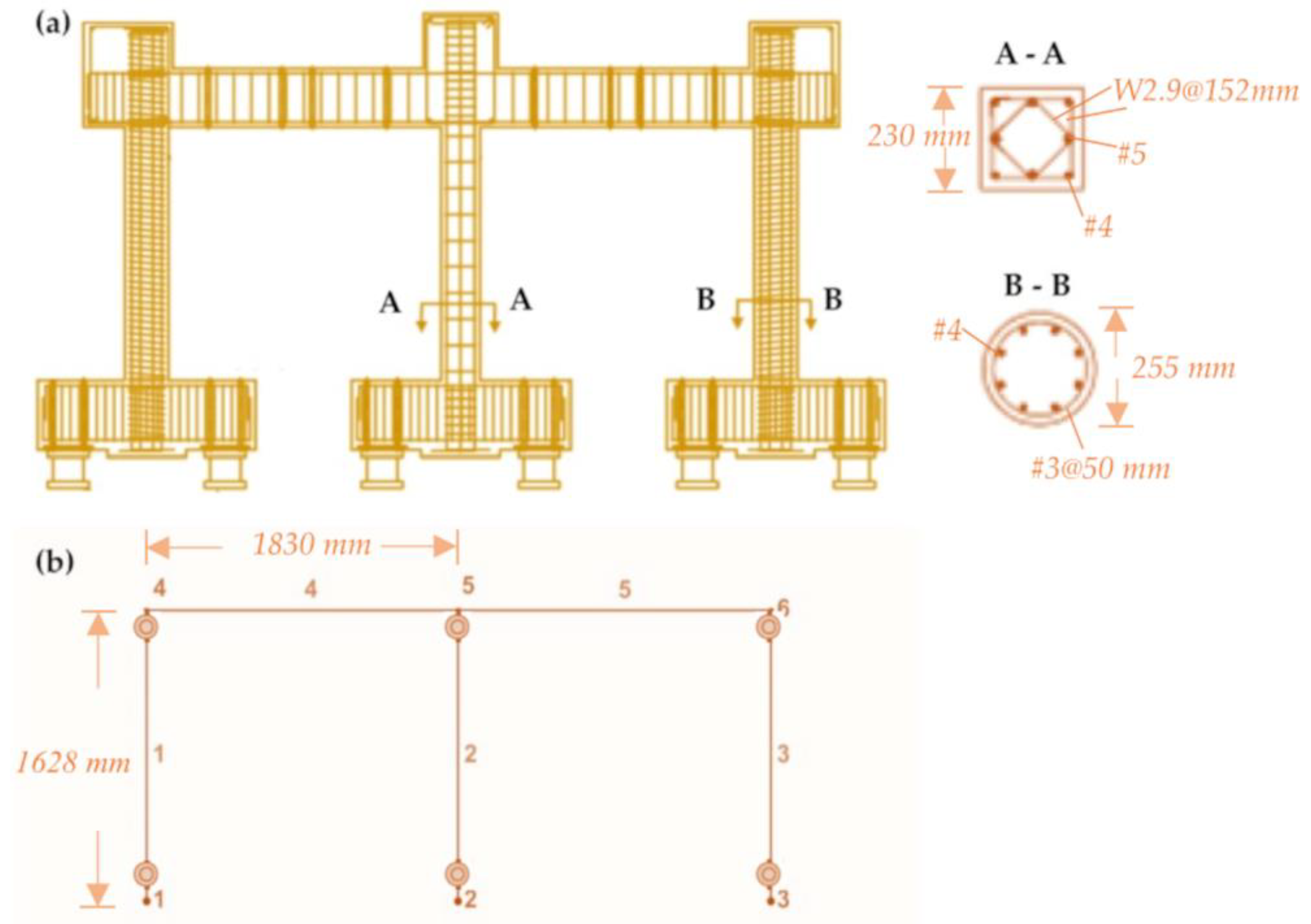
| Elwood and Moehle [37,38] – (Spec. 2 – Center Column) | 308.132 | 230 230 |
814 298 |
25.4 | 24.27 | 4 and 4 12.7 and 15.875 0.0245 |
479.18 |
717 152 4.9 0.00236 |
Disclaimer/Publisher’s Note: The statements, opinions and data contained in all publications are solely those of the individual author(s) and contributor(s) and not of MDPI and/or the editor(s). MDPI and/or the editor(s) disclaim responsibility for any injury to people or property resulting from any ideas, methods, instructions or products referred to in the content. |
© 2024 by the authors. Licensee MDPI, Basel, Switzerland. This article is an open access article distributed under the terms and conditions of the Creative Commons Attribution (CC BY) license (http://creativecommons.org/licenses/by/4.0/).


